Embed Size (px)
Citation preview
DUCT CABLE/WIRE SIZE FILL CHARTDIAMETER AREA (In2) 40% FILL*
CABLE/WIRE SIZE No. 2 No. 4 Inches [mm] Inches [mm] DUCT DUCT
UNSHIELDED 4-PAIR, 24 AWG, CAT 5 0.220 [5.6] 0.038 [24.5] 35 91TWISTED PAIR 4-PAIR, 24 AWG, CAT 6 0.250 [6.4] 0.049 [31.7] 27 71
TELEPHONE 2-PAIR, 24 AWG 0.140 [3.6] 0.015 [9.9] 86 2264-PAIR, 24 AWG 0.190 [4.8] 0.028 [18.1] 47 122
25-PAIR, 24 AWG 0.410 [10.4] 0.132 [85.2] 10 26
COAXIAL RG58/U 0.195 [4.9] 0.030 [19.4] 44 116RG59/U 0.242 [6.1] 0.046 [29.7] 29 75RG6/U 0.270 [6.8] 0.057 [36.8] 23 61
SHIELDED TYPE 1 0.390 [9.9] 0.119 [76.8] 11 29TWISTED PAIR TYPE 2 0.465 [11.8] 0.170 [109.7] 7 20
TYPE 3 0.245 [6.2] 0.047 [30.3] 28 74
FIBER OPTIC 2-STRAND 0.180 [4.6] 0.025 [16.1] 53 1394-STRAND 0.190 [4.8] 0.028 [18.1] 47 1246-STRAND 0.210 [5.3] 0.035 [22.6] 38 99FIBER ZIPCORD 0.110 [2.8] 0.010 [6.5] 133 348
THHN/THWN/ 14 AWG 0.111 [2.8] 0.0097 [6.3] 137 359THWN-2 12 AWG 0.130 [3.3] 0.0133 [8.6] 100 262
10 AWG 0.164 [4.2] 0.0211 [13.6] 63 1658 AWG 0.216 [5.5] 0.0366 [23.6] 36 956 AWG 0.254 [6.5] 0.0507 [32.7] 26 684 AWG 0.324 [8.2] 0.0824 [53.2] 16 42
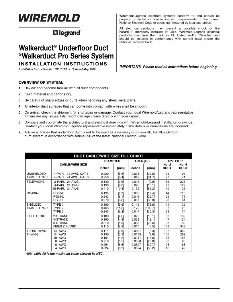
Wiremold/Legrand electrical systems conform to and should be properly grounded in compliance with requirements of the currentNational Electrical Code or codes administered by local authorities.
All electrical products may present a possible shock or fire hazard if improperly installed or used. Wiremold/Legrand electricalproducts may bear the mark as UL Listed and/or Classified and should be installed in conformance with current local and/or the National Electrical Code.
OVERVIEW OF SYSTEM:1. Review and become familiar with all duct components.
2. Keep material and cartons dry.
3. Be careful of sharp edges or burrs when handling any sheet metal parts.
4. All interior duct surfaces that can come into contact with wires shall be smooth.
5. On arrival, check the shipment for shortages or damage. Contact your local Wiremold/Legrand representative if there are any issues. File freight damage claims directly with your carrier.
6. Compare and coordinate the architectural and electrical drawings with Wiremold/Legrand installation drawings. Contact your local Wiremold/Legrand representative immediately if any details or dimensions are incorrect.
7. Advise all trades that underfloor duct is not to be used as a walkway or crosswalk. Install underfloor duct system in accordance with Article 390 of the latest National Electric Code.
Walkerduct® Underfloor Duct®Walkerduct Pro Series SystemINSTALLATION INSTRUCTIONSInstallation Instruction No.: 1B0161R3 – Updated May 2009
IMPORTANT: Please read all instructions before beginning.
*40% cable fill is the maximum cable allowed by NEC.
2
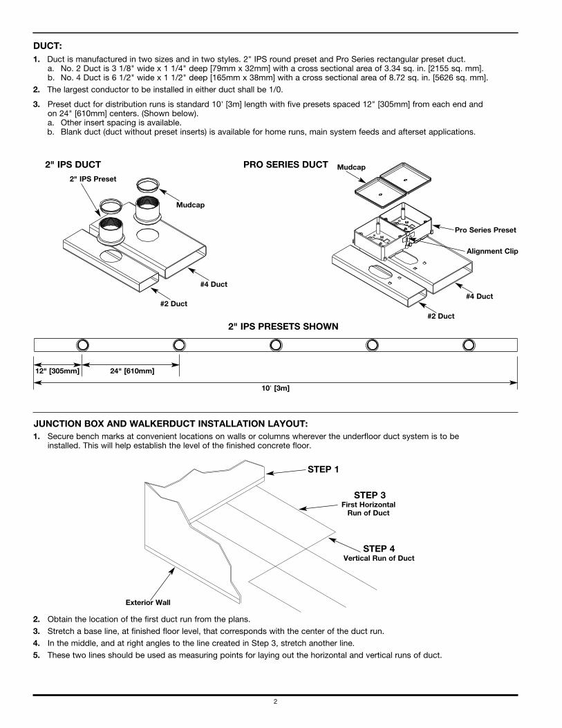
JUNCTION BOX AND WALKERDUCT INSTALLATION LAYOUT:1. Secure bench marks at convenient locations on walls or columns wherever the underfloor duct system is to be
installed. This will help establish the level of the finished concrete floor.
2. Obtain the location of the first duct run from the plans. 3. Stretch a base line, at finished floor level, that corresponds with the center of the duct run.4. In the middle, and at right angles to the line created in Step 3, stretch another line.5. These two lines should be used as measuring points for laying out the horizontal and vertical runs of duct.
2" IPS PRESETS SHOWN
12" [305mm] 24" [610mm]
10' [3m]
Exterior Wall
STEP 1
STEP 3First Horizontal Run of Duct
STEP 4Vertical Run of Duct
2" IPS DUCT PRO SERIES DUCT
2" IPS Preset
#4 Duct
#2 Duct
#2 Duct
Mudcap
#4 Duct
Alignment Clip
Pro Series Preset
Mudcap
DUCT:1. Duct is manufactured in two sizes and in two styles. 2" IPS round preset and Pro Series rectangular preset duct.
a. No. 2 Duct is 3 1/8" wide x 1 1/4" deep [79mm x 32mm] with a cross sectional area of 3.34 sq. in. [2155 sq. mm].b. No. 4 Duct is 6 1/2" wide x 1 1/2" deep [165mm x 38mm] with a cross sectional area of 8.72 sq. in. [5626 sq. mm].
2. The largest conductor to be installed in either duct shall be 1/0.
3. Preset duct for distribution runs is standard 10' [3m] length with five presets spaced 12" [305mm] from each end andon 24" [610mm] centers. (Shown below).a. Other insert spacing is available.b. Blank duct (duct without preset inserts) is available for home runs, main system feeds and afterset applications.
3
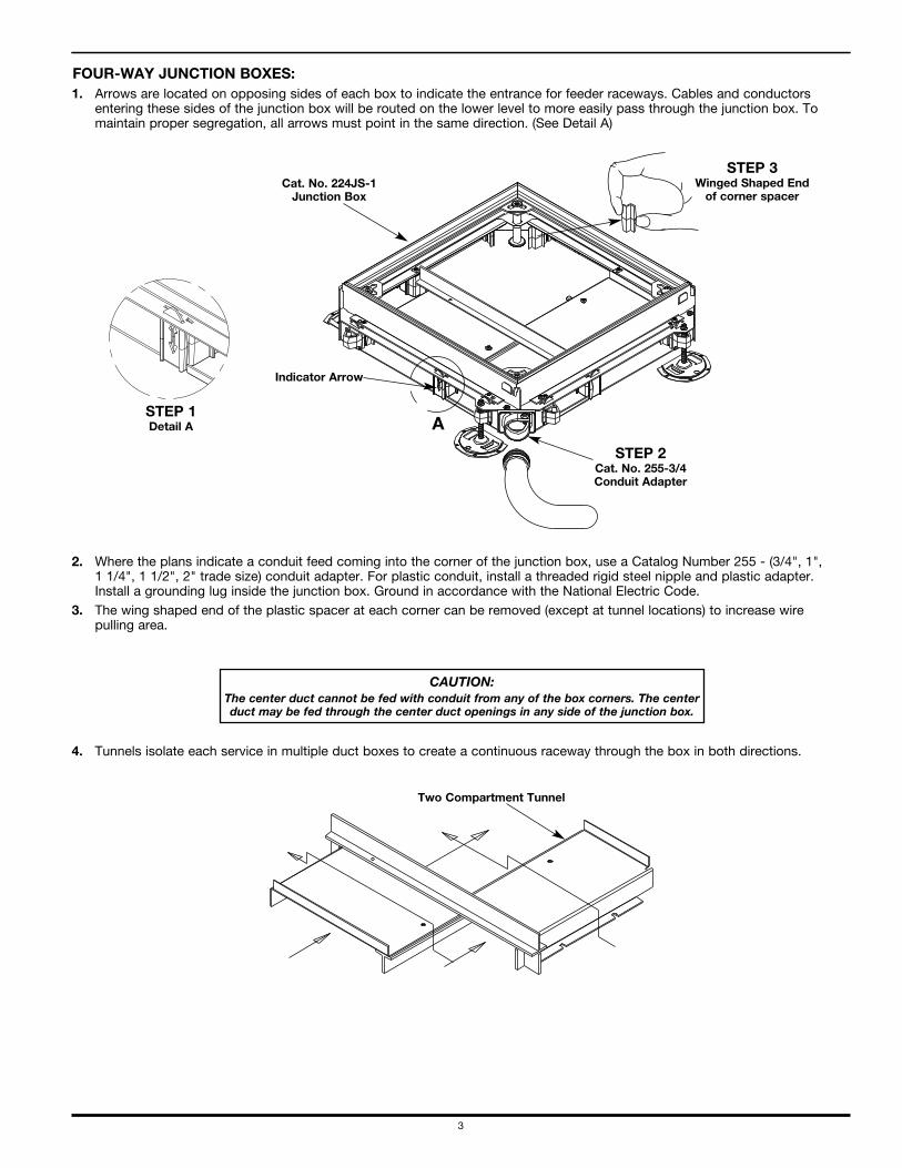
FOUR-WAY JUNCTION BOXES:1. Arrows are located on opposing sides of each box to indicate the entrance for feeder raceways. Cables and conductors
entering these sides of the junction box will be routed on the lower level to more easily pass through the junction box. Tomaintain proper segregation, all arrows must point in the same direction. (See Detail A)
2. Where the plans indicate a conduit feed coming into the corner of the junction box, use a Catalog Number 255 - (3/4", 1", 1 1/4", 1 1/2", 2" trade size) conduit adapter. For plastic conduit, install a threaded rigid steel nipple and plastic adapter.Install a grounding lug inside the junction box. Ground in accordance with the National Electric Code.
3. The wing shaped end of the plastic spacer at each corner can be removed (except at tunnel locations) to increase wire pulling area.
4. Tunnels isolate each service in multiple duct boxes to create a continuous raceway through the box in both directions.
Two Compartment Tunnel
Cat. No. 224JS-1Junction Box
STEP 1Detail A
Indicator Arrow
A
STEP 2Cat. No. 255-3/4Conduit Adapter
STEP 3Winged Shaped Endof corner spacer
CAUTION:The center duct cannot be fed with conduit from any of the box corners. The centerduct may be fed through the center duct openings in any side of the junction box.
4
Junction Box Distance Between Duct EndsCatalog Number Within Junction Box
12JS, JR, HS, or HR 7" [178mm]14JS, JR, HS, or HR 11 1/8" [283mm]222JS, JR, HS, or HR 11 1/8" [283mm]224JS, JR, HS, or HR 15 1/4" [387mm]3222JS, JR, HS, or HR 15 1/4" [387mm]244JS, JR, HS, or HR 18 5/8" [473mm]3224JS, JR, HS, or HR 18 5/8" [473mm]42222JS, JR, HS, or HR 19 3/8" [492mm]3424JS, JR, HS, or HR 22" [559mm]3244JS, JR, HS, or HR 22" [559mm]522222JS, JR, HS, or HR 23 1/2" [597mm]3444JS, JR, HS, or HR 25 3/8" [645mm]
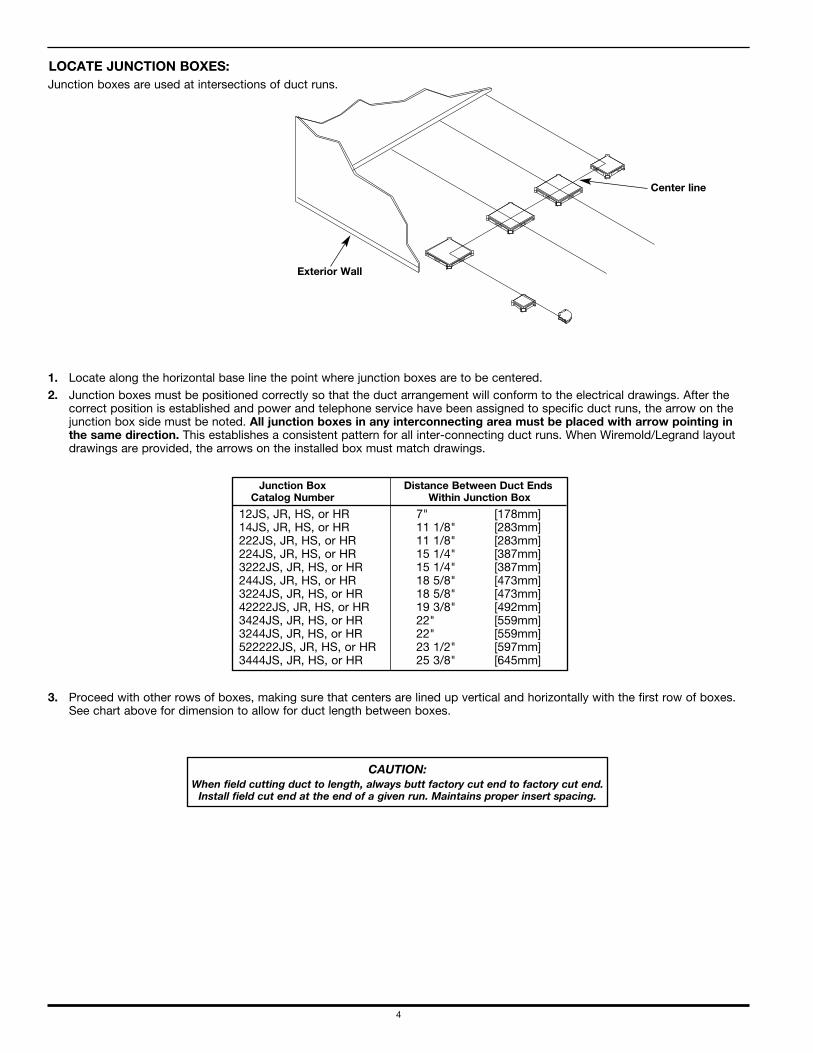
LOCATE JUNCTION BOXES:Junction boxes are used at intersections of duct runs.
1. Locate along the horizontal base line the point where junction boxes are to be centered.2. Junction boxes must be positioned correctly so that the duct arrangement will conform to the electrical drawings. After the
correct position is established and power and telephone service have been assigned to specific duct runs, the arrow on thejunction box side must be noted. All junction boxes in any interconnecting area must be placed with arrow pointing inthe same direction. This establishes a consistent pattern for all inter-connecting duct runs. When Wiremold/Legrand layoutdrawings are provided, the arrows on the installed box must match drawings.
3. Proceed with other rows of boxes, making sure that centers are lined up vertical and horizontally with the first row of boxes.See chart above for dimension to allow for duct length between boxes.
Exterior Wall
Center line
CAUTION:When field cutting duct to length, always butt factory cut end to factory cut end. Install field cut end at the end of a given run. Maintains proper insert spacing.
5
CAUTION:
A solid foundation of grout or concretemust be provided beneath the entirejunction box to prevent excessive coverplate deflection and damage. Vibrateconcrete at junction box and duct toinsure that concrete completely fillsunderneath the system.
CAUTION:
Heavy rolling loads during construction candamage cover plate. Install 3/4" [19.1mm]
planking over all junction boxes.
CAUTION:
A vapor barrier is recommendedwhen duct is installed directly ongrade to prevent ground moisturefrom reaching the underside ofconcrete slab.
Prepour a work slab, pads, orsidewalk to protect vapor barrier frompenetration of anchoring means.
CAUTION:
Do not use concreteadditive containingchlorides. This willcause severe rusting of the duct system.
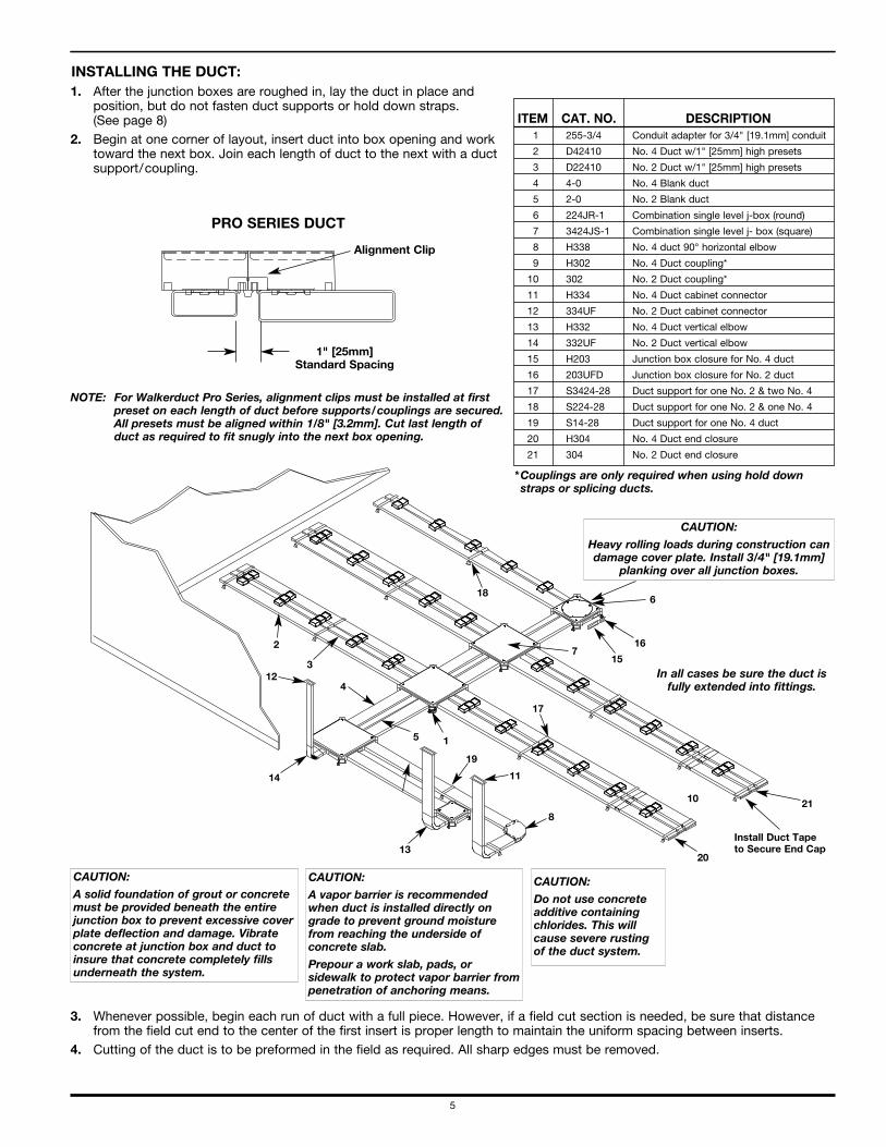
Install Duct Tape to Secure End Cap
In all cases be sure the duct isfully extended into fittings.
15
21
19
11
18
20
10
14
5
7
8
1
4
13
123
2
6
17
16
INSTALLING THE DUCT:1. After the junction boxes are roughed in, lay the duct in place and
position, but do not fasten duct supports or hold down straps. (See page 8)
2. Begin at one corner of layout, insert duct into box opening and worktoward the next box. Join each length of duct to the next with a ductsupport/coupling.
3. Whenever possible, begin each run of duct with a full piece. However, if a field cut section is needed, be sure that distancefrom the field cut end to the center of the first insert is proper length to maintain the uniform spacing between inserts.
4. Cutting of the duct is to be preformed in the field as required. All sharp edges must be removed.
PRO SERIES DUCT
Alignment Clip
1" [25mm] Standard Spacing
NOTE: For Walkerduct Pro Series, alignment clips must be installed at firstpreset on each length of duct before supports/couplings are secured.All presets must be aligned within 1/8" [3.2mm]. Cut last length ofduct as required to fit snugly into the next box opening.
ITEM CAT. NO. DESCRIPTION1 255-3/4 Conduit adapter for 3/4" [19.1mm] conduit
2 D42410 No. 4 Duct w/1" [25mm] high presets
3 D22410 No. 2 Duct w/1" [25mm] high presets
4 4-0 No. 4 Blank duct
5 2-0 No. 2 Blank duct
6 224JR-1 Combination single level j-box (round)
7 3424JS-1 Combination single level j- box (square)
8 H338 No. 4 duct 90° horizontal elbow
9 H302 No. 4 Duct coupling*
10 302 No. 2 Duct coupling*
11 H334 No. 4 Duct cabinet connector
12 334UF No. 2 Duct cabinet connector
13 H332 No. 4 Duct vertical elbow
14 332UF No. 2 Duct vertical elbow
15 H203 Junction box closure for No. 4 duct
16 203UFD Junction box closure for No. 2 duct
17 S3424-28 Duct support for one No. 2 & two No. 4
18 S224-28 Duct support for one No. 2 & one No. 4
19 S14-28 Duct support for one No. 4 duct
20 H304 No. 4 Duct end closure
21 304 No. 2 Duct end closure
*Couplings are only required when using hold downstraps or splicing ducts.
6
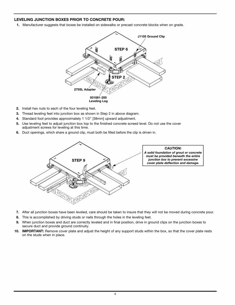
LEVELING JUNCTION BOXES PRIOR TO CONCRETE POUR:1. Manufacturer suggests that boxes be installed on sidewalks or precast concrete blocks when on grade.
2. Install hex nuts to each of the four leveling feet.
3. Thread leveling feet into junction box as shown in Step 2 in above diagram.4. Standard foot provides approximately 1 1/2" [38mm] upward adjustment.5. Use leveling feet to adjust junction box top to the finished concrete screed level. Do not use the cover
adjustment screws for leveling at this time.6. Duct openings, which share a ground clip, must both be filled before the clip is driven in.
7. After all junction boxes have been leveled, care should be taken to insure that they will not be moved during concrete pour.
8. This is accomplished by driving studs or nails through the holes in the leveling feet.9. When junction boxes and duct are correctly leveled and in final position, drive in ground clips on the junction boxes to
secure duct and provide ground continuity.10. IMPORTANT: Remove cover plate and adjust the height of any support studs within the box, so that the cover plate rests
on the studs when in place.
CAUTION:A solid foundation of grout or concrete must be provided beneath the entire junction box to prevent excessive cover plate deflection and damage.
931081-200Leveling Leg
275SL Adapter
J1105 Ground Clip
STEP 2
STEP 6
STEP 9
7
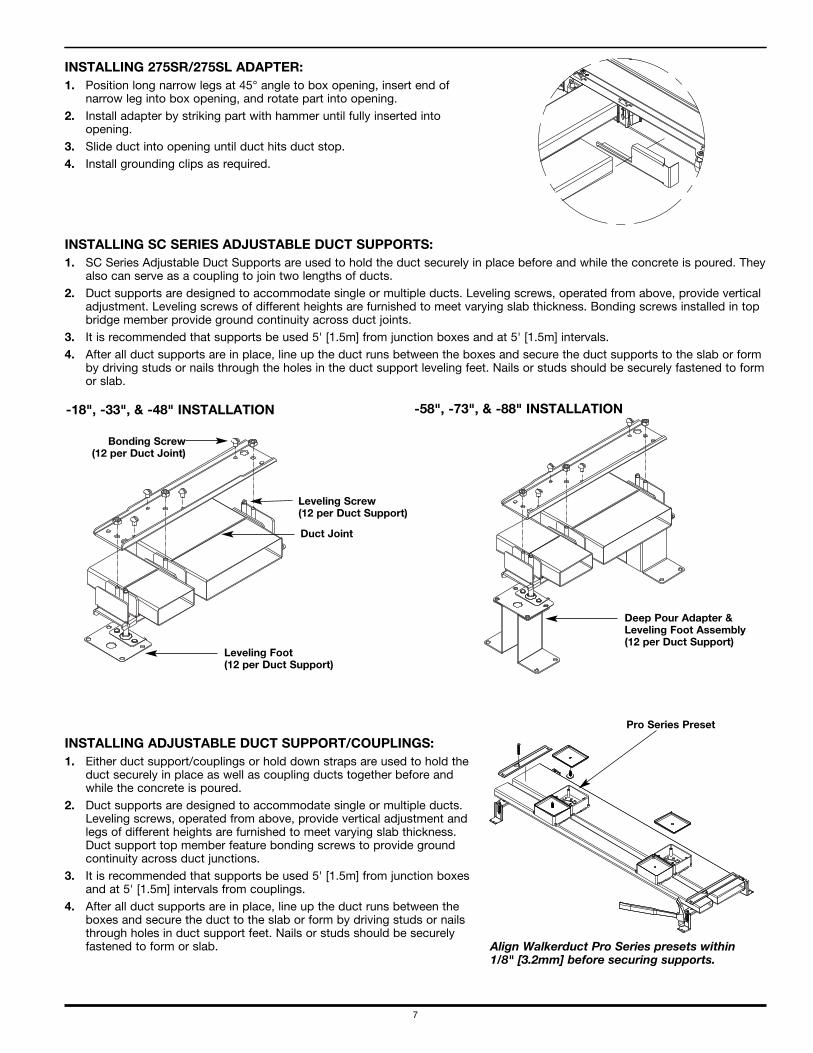
INSTALLING 275SR/275SL ADAPTER:1. Position long narrow legs at 45° angle to box opening, insert end of
narrow leg into box opening, and rotate part into opening.2. Install adapter by striking part with hammer until fully inserted into
opening.3. Slide duct into opening until duct hits duct stop.4. Install grounding clips as required.
INSTALLING ADJUSTABLE DUCT SUPPORT/COUPLINGS:1. Either duct support/couplings or hold down straps are used to hold the
duct securely in place as well as coupling ducts together before andwhile the concrete is poured.
2. Duct supports are designed to accommodate single or multiple ducts.Leveling screws, operated from above, provide vertical adjustment andlegs of different heights are furnished to meet varying slab thickness.Duct support top member feature bonding screws to provide groundcontinuity across duct junctions.
3. It is recommended that supports be used 5' [1.5m] from junction boxesand at 5' [1.5m] intervals from couplings.
4. After all duct supports are in place, line up the duct runs between theboxes and secure the duct to the slab or form by driving studs or nailsthrough holes in duct support feet. Nails or studs should be securelyfastened to form or slab.
INSTALLING SC SERIES ADJUSTABLE DUCT SUPPORTS:1. SC Series Adjustable Duct Supports are used to hold the duct securely in place before and while the concrete is poured. They
also can serve as a coupling to join two lengths of ducts.2. Duct supports are designed to accommodate single or multiple ducts. Leveling screws, operated from above, provide vertical
adjustment. Leveling screws of different heights are furnished to meet varying slab thickness. Bonding screws installed in topbridge member provide ground continuity across duct joints.
3. It is recommended that supports be used 5' [1.5m] from junction boxes and at 5' [1.5m] intervals.4. After all duct supports are in place, line up the duct runs between the boxes and secure the duct supports to the slab or form
by driving studs or nails through the holes in the duct support leveling feet. Nails or studs should be securely fastened to formor slab.
Align Walkerduct Pro Series presets within1/8" [3.2mm] before securing supports.
Pro Series Preset
Bonding Screw(12 per Duct Joint)
Leveling Screw(12 per Duct Support)
Duct Joint
Leveling Foot(12 per Duct Support)
Deep Pour Adapter &Leveling Foot Assembly(12 per Duct Support)
-18", -33", & -48" INSTALLATION -58", -73", & -88" INSTALLATION
8
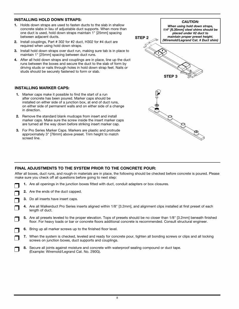
INSTALLING HOLD DOWN STRAPS:1. Holds down straps are used to fasten ducts to the slab in shallow
concrete slabs in lieu of adjustable duct supports. When more than one duct is used, hold down straps maintain 1" [25mm] spacingbetween adjacent ducts.
2. Install couplings, Part # 302 for #2 duct, H302 for #4 duct are required when using hold down straps.
3. Install hold down straps over duct run, making sure tab is in place tomaintain 1" [25mm] spacing between duct runs.
4. After all hold down straps and couplings are in place, line up the ductruns between the boxes and secure the duct to the slab of form bydriving studs or nails through holes in hold down strap feet. Nails orstuds should be securely fastened to form or slab.
CAUTION:When using hold down straps,
1/4" [6.35mm] steel shims should beplaced under #2 duct to
maintain proper preset height.(Wiremold/Legrand Cat. # Duct shim)
STEP 2
STEP 3
INSTALLING MARKER CAPS:
1. Marker caps make it possible to find the start of a run after concrete has been poured. Marker caps should be installed on either side of a junction box, at end of duct runs, on either side of permanent walls and on either side of a change in direction.
2. Remove the standard blank mudcaps from insert and install marker caps. Make sure the screw inside the insert marker caps are turned all the way down before striking insert marker cap.
3. For Pro Series Marker Caps. Markers are plastic and protrude approximately 3" [76mm] above preset. Trim height to match screed line.
FINAL ADJUSTMENTS TO THE SYSTEM PRIOR TO THE CONCRETE POUR:After all boxes, duct runs, and rough-in materials are in place, the following should be checked before concrete is poured. Pleasemake sure you check off all questions before going to next step:
1. Are all openings in the junction boxes fitted with duct, conduit adapters or box closures.
2. Are the ends of the duct capped.
3. Do all inserts have insert caps.
4. Are all Walkerduct Pro Series inserts aligned within 1/8" [3.2mm], and alignment clips installed at first preset of eachlength of duct.
5. Are all presets leveled to the proper elevation. Tops of presets should be no closer than 1/8" [3.2mm] beneath finishedfloor. For heavy loads or bar or concrete floors additional concrete is recommended. Consult structural engineer.
6. Bring up all marker screws up to the finished floor level.
7. When the system is checked, leveled and ready for concrete pour, tighten all bonding screws or clips and all lockingscrews on junction boxes, duct supports and couplings.
8. Secure all joints against moisture and concrete with waterproof sealing compound or duct tape. (Example: Wiremold/Legrand Cat. No. 290G).
r
r
r
r
r
r
r
r
9
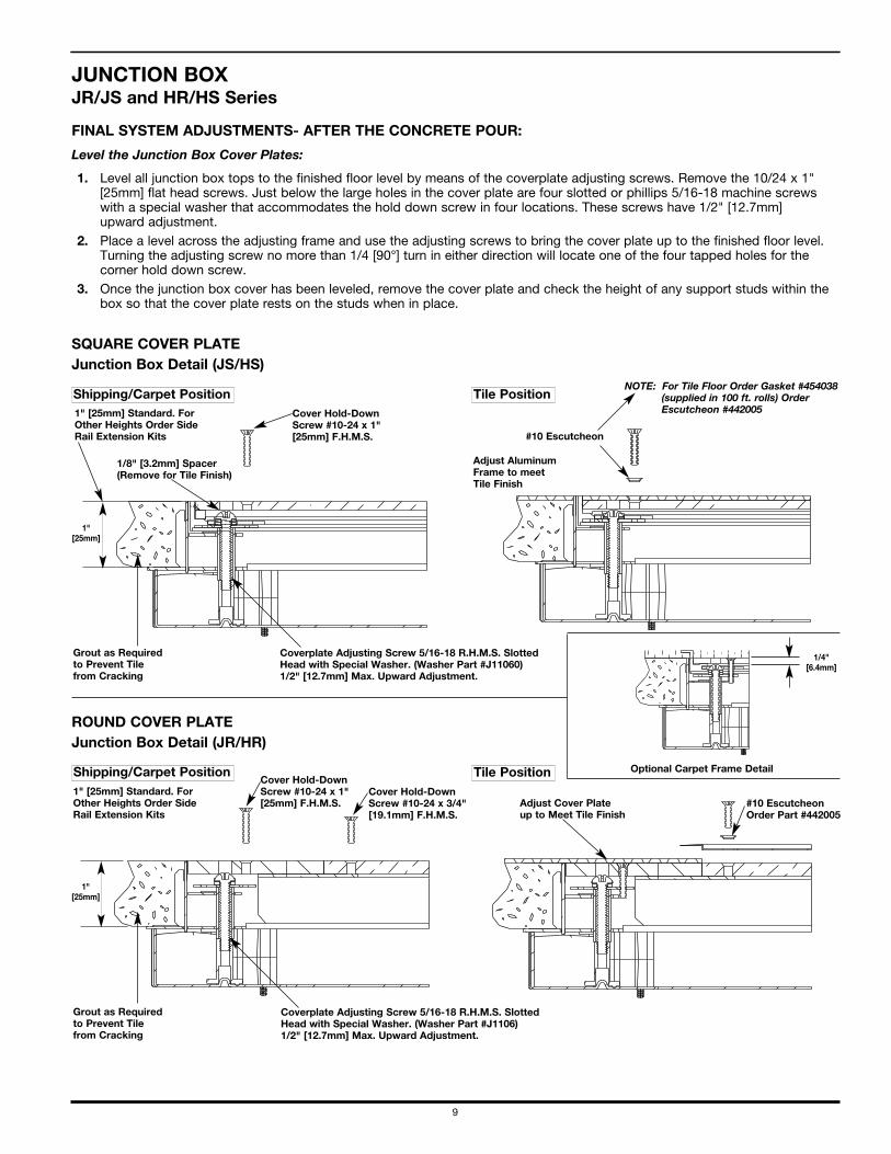
JUNCTION BOXJR/JS and HR/HS Series
SQUARE COVER PLATE Junction Box Detail (JS/HS)
ROUND COVER PLATE Junction Box Detail (JR/HR)
Cover Hold-DownScrew #10-24 x 1"[25mm] F.H.M.S.
Cover Hold-DownScrew #10-24 x 1"[25mm] F.H.M.S.
Cover Hold-DownScrew #10-24 x 3/4"[19.1mm] F.H.M.S.
#10 EscutcheonOrder Part #442005
Adjust Cover Plate up to Meet Tile Finish
1/8" [3.2mm] Spacer(Remove for Tile Finish)
Optional Carpet Frame Detail
#10 Escutcheon
1" [25mm] Standard. ForOther Heights Order SideRail Extension Kits
1" [25mm] Standard. ForOther Heights Order SideRail Extension Kits
Grout as Requiredto Prevent Tilefrom Cracking
Grout as Requiredto Prevent Tilefrom Cracking
NOTE: For Tile Floor Order Gasket #454038(supplied in 100 ft. rolls) OrderEscutcheon #442005
Coverplate Adjusting Screw 5/16-18 R.H.M.S. SlottedHead with Special Washer. (Washer Part #J11060) 1/2" [12.7mm] Max. Upward Adjustment.
Coverplate Adjusting Screw 5/16-18 R.H.M.S. SlottedHead with Special Washer. (Washer Part #J1106) 1/2" [12.7mm] Max. Upward Adjustment.
Adjust AluminumFrame to meetTile Finish
Shipping/Carpet Position
Shipping/Carpet Position
Tile Position
Tile Position
1/4"[6.4mm]
1"[25mm]
1"[25mm]
FINAL SYSTEM ADJUSTMENTS- AFTER THE CONCRETE POUR:
Level the Junction Box Cover Plates:
1. Level all junction box tops to the finished floor level by means of the coverplate adjusting screws. Remove the 10/24 x 1"[25mm] flat head screws. Just below the large holes in the cover plate are four slotted or phillips 5/16-18 machine screwswith a special washer that accommodates the hold down screw in four locations. These screws have 1/2" [12.7mm] upward adjustment.
2. Place a level across the adjusting frame and use the adjusting screws to bring the cover plate up to the finished floor level.Turning the adjusting screw no more than 1/4 [90°] turn in either direction will locate one of the four tapped holes for thecorner hold down screw.
3. Once the junction box cover has been leveled, remove the cover plate and check the height of any support studs within thebox so that the cover plate rests on the studs when in place.
10
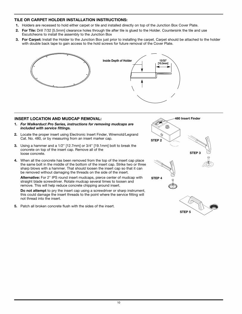
TILE OR CARPET HOLDER INSTALLATION INSTRUCTIONS:1. Holders are recessed to hold either carpet or tile and installed directly on top of the Junction Box Cover Plate.2. For Tile: Drill 7/32 [5.5mm] clearance holes through tile after tile is glued to the Holder. Countersink the tile and use
Escutcheons to install the assembly to the Junction Box3. For Carpet: Install the Holder to the Junction Box just prior to installing the carpet. Carpet should be attached to the holder
with double back tape to gain access to the hold screws for future removal of the Cover Plate.
Inside Depth of Holder 13/32"[10.3mm]
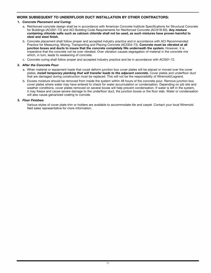
INSERT LOCATION AND MUDCAP REMOVAL:1. For Walkerduct Pro Series, instructions for removing mudcaps are
included with service fittings.
480 Insert Finder
STEP 2
2. Locate the proper insert using Electronic Insert Finder, Wiremold/LegrandCat. No. 480, or by measuring from an insert marker cap.
STEP 3
3. Using a hammer and a 1/2" [12.7mm] or 3/4" [19.1mm] bolt to break theconcrete on top of the insert cap. Remove all of the loose concrete.
STEP 4
4. When all the concrete has been removed from the top of the insert cap placethe same bolt in the middle of the bottom of the insert cap. Strike two or threesharp blows with a hammer. That should loosen the insert cap so that it canbe removed without damaging the threads on the side of the insert. Alternative: For 2" IPS round insert mudcaps, pierce center of mudcap withstraight blade screwdriver. Rotate mudcap several times to loosen andremove. This will help reduce concrete chipping around insert. Do not attempt to pry the insert cap using a screwdriver or sharp instrument,this could damage the insert threads to the point where the service fitting willnot thread into the insert.
STEP 5
5. Patch all broken concrete flush with the sides of the insert.
11
WORK SUBSEQUENT TO UNDERFLOOR DUCT INSTALLATION BY OTHER CONTRACTORS: 1. Concrete Placement and Curing:
a. Reinforced concrete design shall be in accordance with American Concrete Institute Specifications for Structural Concretefor Buildings (ACI301-72) and ACI Building Code Requirements for Reinforced Concrete (ACI318-83). Any mixturecontaining chloride salts such as calcium chloride shall not be used, as such mixtures have proven harmful to steel and steel finish.
b. Concrete placement shall follow proper and accepted industry practice and in accordance with ACI RecommendedPractice for Measuring, Mixing, Transporting and Placing Concrete (ACI304-73). Concrete must be vibrated at alljunction boxes and ducts to insure that the concrete completely fills underneath the system. However, it isimperative that the concrete not be over vibrated. Over vibration causes segregation of material in the concrete mix which, in turn, leads to weakening of concrete.
c. Concrete curing shall follow proper and accepted industry practice and be in accordance with ACI301-72.
2. After the Concrete Pour:a. When material or equipment loads that could deform junction box cover plates will be placed or moved over the cover
plates, install temporary planking that will transfer loads to the adjacent concrete. Cover plates and underfloor ductthat are damaged during construction must be replaced. This will not be the responsibility of Wiremold/Legrand.
b. Excess moisture should be removed from inside the system within 48 hours of the concrete pour. Remove junction boxcover plates where water may have entered to check for water accumulation or condensation. Depending on job site andweather conditions, cover plates removed on several boxes will help prevent condensation. If water is left in the system, it may freeze and cause severe damage to the underfloor duct, the junction boxes or the floor slab. Water or condensationwill also cause galvanized coating to corrode.
3. Floor Finishes:Various styles of cover plate trim or holders are available to accommodate tile and carpet. Contact your local Wiremoldfield sales representative for more information.
Wiremold/LegrandU.S. and International: 60 Woodlawn Street • West Hartford, CT 061101-800-621-0049 • FAX 860-232-2062 • Outside U.S.: 860-233-6251 Canada:570 Applewood Crescent • Vaughan, Ontario L4K 4B41-800-723-5175 • FAX 905-738-9721
© Copyright 2009 Wiremold/Legrand All Rights Reserved IB0161R3 0509
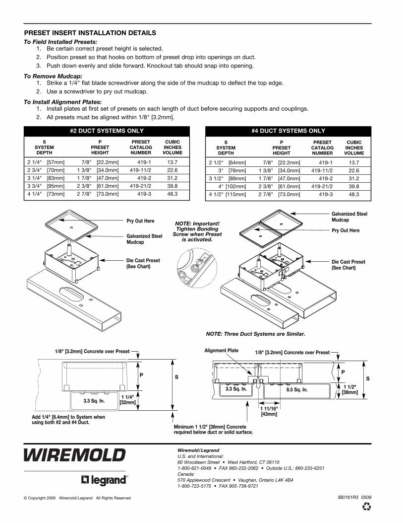
PRESET INSERT INSTALLATION DETAILSTo Field Installed Presets:
1. Be certain correct preset height is selected.2. Position preset so that hooks on bottom of preset drop into openings on duct.3. Push down evenly and slide forward. Knockout tab should snap into opening.
To Remove Mudcap:1. Strike a 1/4" flat blade screwdriver along the side of the mudcap to deflect the top edge.2. Use a screwdriver to pry out mudcap.
To Install Alignment Plates:1. Install plates at first set of presets on each length of duct before securing supports and couplings.2. All presets must be aligned within 1/8" [3.2mm].
S P PRESET CUBICSYSTEM PRESET CATALOG INCHESDEPTH HEIGHT NUMBER VOLUME
2 1/4" [57mm] 7/8" [22.2mm] 419-1 13.7
2 3/4" [70mm] 1 3/8" [34.0mm] 419-11/2 22.6
3 1/4" [83mm] 1 7/8" [47.0mm] 419-2 31.2
3 3/4" [95mm] 2 3/8" [61.0mm] 419-21/2 39.8
4 1/4" [73mm] 2 7/8" [73.0mm] 419-3 48.3
S P PRESET CUBICSYSTEM PRESET CATALOG INCHESDEPTH HEIGHT NUMBER VOLUME
2 1/2" [64mm] 7/8" [22.2mm] 419-1 13.7
3" [76mm] 1 3/8" [34.0mm] 419-11/2 22.6
3 1/2" [89mm] 1 7/8" [47.0mm] 419-2 31.2
4" [102mm] 2 3/8" [61.0mm] 419-21/2 39.8
4 1/2" [115mm] 2 7/8" [73.0mm] 419-3 48.3
#2 DUCT SYSTEMS ONLY #4 DUCT SYSTEMS ONLY
Galvanized SteelMudcap
Pry Out Here
Die Cast Preset(See Chart)
NOTE: Three Duct Systems are Similar.
Alignment Plate
3.3 Sq. In. 8.5 Sq. In.
PS
1 1/2"[38mm]
1/8" [3.2mm] Concrete over Preset
1 11/16"[43mm]
Galvanized SteelMudcap
Pry Out Here
Die Cast Preset(See Chart)
NOTE: Important!Tighten Bonding
Screw when Preset is activated.
3.3 Sq. In.
1/8" [3.2mm] Concrete over Preset
P S
1 1/4"[32mm]
Add 1/4" [6.4mm] to System when using both #2 and #4 Duct.
Minimum 1 1/2" [38mm] Concreterequired below duct or solid surface.