Embed Size (px)
Citation preview
Journal of Engineering Science and Technology Vol. 14, No. 4 (2019) 2152 - 2170 © School of Engineering, Taylor’s University
2152
PERFORMANCE OF CEMENT CLAY INTERLOCKING HOLLOW BRICK MASONRY WALLS
SUBJECTED TO DIAGONAL COMPRESSION
PANUWAT JOYKLAD1,*, QUDEER HUSSAIN2
1Department of Civil and Environmental Engineering,
Srinakharinwirot University, Thailand 2Construction and Maintenance Technology Research Center (CONTEC),
School of Civil Engineering and Technology, Sirindhorn International Institute
of Technology, Thammasat University, Pathumthani, Thailand
*Corresponding Author: [email protected]
Abstract
This study presents an experimental investigation on the diagonal compressive
response of cement-clay interlocking (CCI) hollow brick masonry walls. The
diagonal compressive responses of the masonry walls were investigated by
performing laboratory tests on large size (1000×1000×125 mm) CCI hollow
brick masonry walls. CCI hollow brick masonry walls were constructed using
different techniques to represent existing construction practice in Thailand. A
total of five masonry walls were constructed and tested under diagonal
compression. One masonry wall was constructed by dry stacking of CCI hollow
bricks over each other in the running bond pattern without using any binding
material (i.e., un-grouted masonry wall). In the second and third walls, circular
and square holes in the CCI bricks were filled with Ordinary Portland Cement
(OPC)-Sand grout and high-performance non-shrink cement-sand grout,
respectively. The remaining two walls (i.e., wall number 4 and 5) were similar to
the wall number two and three, however, prior to the grout filling, steel bars were
also inserted into the holes at different locations to reinforce the masonry walls.
It was evidenced from the experimental results that cement grout impact, shear
strength and shear modulus of the CCI brick masonry walls. It was also noticed
that the reinforced CCI hollow brick masonry walls showed very ductile failure
mechanism as compared with unreinforced masonry walls along with an increase
in the ultimate diagonal load carrying capacity of the CCI masonry walls.
Keywords: Cement, Clay, Grout and masonry, Interlocking bricks, Shear Modulus,
Shear strength.
Performance of Cement Clay Interlocking Hollow Brick Masonry Walls . . . . 2153
Journal of Engineering Science and Technology August 2019, Vol. 14(4)
1. Introduction
Masonry is one of the oldest building materials known to the man and is believed
to have been in use for over 6000 years. Construction using masonry remains
relatively popular in many parts of the world and is practiced widely even today.
Masonry is composed of two different materials, namely: the masonry units and the
mortar phase. Masonry units may be either solid or hollow and may be made of a
wide variety of materials. Clay bricks, blocks of stone, concrete blocks, pressed
earth bricks, calcium silicate bricks, soft mud bricks, etc. Are some examples of
masonry units used in masonry construction [1].
Several experimental studies have been carried out on the compression
behaviour of masonry under different load cases [2-9], including diagonal-
compression, flexural test, uniaxial compression test, cyclic compressive loading,
and so on [10]. The influence of mortar strength, thickness, material of bricks, and
composite systems on the compressive failure were also investigated
experimentally and theoretically [11-14]. Gurumo [15] performed diagonal
compression tests on 1200×1200×250 mm adobe specimens adopting a
reinforcement based on soil-cement bond beams with longitudinal pre-tensioning
steel rods. Results indicated that the pre-stressed specimens carried almost twice
the load of the un-reinforced adobe.
Sathiparan et al. [16] conducted diagonal compression tests on non-reinforced
and polypropylene mesh reinforced adobe masonry wall specimens. The authors
reported that the mesh effect was not observed before the wall crooked. After
cracking, the mesh presence positively influenced the wall behaviour. San
Bartolomé et al. [17] tested four small walls 800×800×180 mm under diagonal
compression to evaluate the shear resistance. Tests were not effective as
detachment occurred during the handling prior to the test, resulting in very low
values for shear resistance, which are not cited in the publication.
Alecci et al. [18] investigated the shear strength of brick masonry walls
assembled with different types of mortar. A comparison between the values of the
masonry shear strength, calculated applying the three formulas available in the
literature for the diagonal compression test data, and those obtained from laboratory
tests on shear triplets was also performed. The strength values obtained by triplet
tests are in good measure along the line of the results determined by diagonal tests
and calculated by formulas.
Yardim and Lalaj [19] performed shear strengthening of un-reinforced masonry
walls with different fiber reinforced mortar jacketing. The walls reinforced with
ferrocement and polypropylene mortar, plaster exhibited a significant improvement
in the shear strength capacity of up to 412% when compared to the control specimen.
The high demand of construction of buildings gives reason to find ways to fulfil
and to solve the problems related to the construction. Interlocking brick system is
an alternative system which is similar to the “LEGO blocks” that use less or
minimum mortar to bind the bricks together. Interlocking bricks were introduced
to reduce the use of manpower, hence fulfil the requirement of Industrialized
Building System (IBS). Interlocking brick system is a fast and cost-effective
construction system, which offers good solution in construction.
Nazar and Sinha [20, 21] investigated the behaviour of interlocking grouted
stabilized sand-fly ash brick masonry under uniaxial cyclic compressive loading.
2154 P. Joyklad and Q. Hussain
Journal of Engineering Science and Technology August 2019, Vol. 14(4)
Five cases of loading at 0, 22.5, 45, 67.5, and 90° with the bed joints were
considered. Results indicate that the load carrying capacity of interlocking grouted
brick masonry is 63% of its unit strength of the specimens loaded perpendicular to
bed joints, whereas the ultimate strength of a conventional masonry system varies
from 30 to 40% of its unit strength.
Ronoh et al. [22] experimentally studied cement effects on the physical
properties of expansive clay soil and the compressive strength of compressed
interlocking clay blocks. The results indicate that the compressive strength of
blocks increased with increase in cement content from 0% to 12% cement content.
Out-of-plane structural responses of interlocking compressed earth block walls
have also been investigated by Laursen et al. [23]. Bland [24] investigated the in-
plane cyclic shear performance of interlocking compressed earth block walls. The
interlocking compressed earth blocks (ICEBs) used in this experiment are dry
stacked interlocking hollow units, which can be reinforced and grouted after they
are laid. It was determined that the shear strength of fully grouted walls is
significantly higher than that of partially grouted walls.
In Thailand, cement-clay interlocking (CCI) bricks made of locally available
red clay are widely used to construct low-rise residential buildings throughout the
country. These interlocking bricks are manufactured locally in small factories
located in the different regions of Thailand. The CCI hollow bricks are usually used
for the construction of load bearing and partition walls in three different ways. In
the first method, the arrangement of the CCI bricks is such that they are placed on
each other in the running bond pattern (without using any mortar and grout) to
construct the masonry structures. In this pattern, the bonding strength is achieved
by using interlocks. Mostly, this type of construction technique is used for load
bearing walls in single-story residential buildings and boundary walls. In the
second method, the construction of the masonry walls is similar to the first method
with the only difference that holes in the CCI hollow bricks are filled with some
kinds of cement-sand grouts to increase the bonding strength of the masonry wall.
Whereas, in the third method, steel bars are also inserted into the holes to further
enhance the bonding strength and lateral stability of the load bearing walls. The
second and third type of construction technique is used for the construction of high-
rise building (mostly 2-4 story building) and commercial facilities. In the past, a
significant research has been undertaken to optimize the material properties of these
CCI hollow bricks [25]. Namboonruang et al. [26], Yoosathaporn et al. [27],
Namboonruang et al. [28], Joyklad [29] and Shakir and Mohammed [30]
investigated the mechanical properties of these CCI hollow brick.
The CCI hollow brick masonry walls are main load carrying elements which
can safely carry vertical loads without severe damages. However, the shear
response of masonry walls is more complex and depends on the composite nature
of interlocks, cement-sand grout and bricks. The determination of shear strength
and shear modulus is very important for analytical predictions. Therefore, the
primary objective of this research was to investigate the diagonal compressive
response and deformability of CCI hollow brick masonry walls representing
existing construction practices in Thailand. To achieve this goal an experimental
program was developed and the diagonal compressive responses of the masonry
walls were investigated by performing laboratory tests on large area
(1000×1000×125 mm) CCI hollow brick masonry walls. CCI hollow brick
Performance of Cement Clay Interlocking Hollow Brick Masonry Walls . . . . 2155
Journal of Engineering Science and Technology August 2019, Vol. 14(4)
masonry walls were constructed using different techniques to represent existing
construction practice in Thailand.
The scope of the research was limited to the diagonal compression loading of
CCI hollow brick masonry walls under static loading. The size of the CCI brick
masonry walls was designed according the available lab facilities such as the size
and the capacity of the loading frame. CCI hollow bricks were collected from the
local manufacturer in Thailand. The experimental results in terms of ultimate load
carrying capacity, diagonal compression and failure modes are briefly discussed
and presented in this research article.
2. Experimental Program
In this study, five CCI hollow brick masonry walls were constructed and tested
under diagonal compression. The details of test matrix are summarized in Table 1.
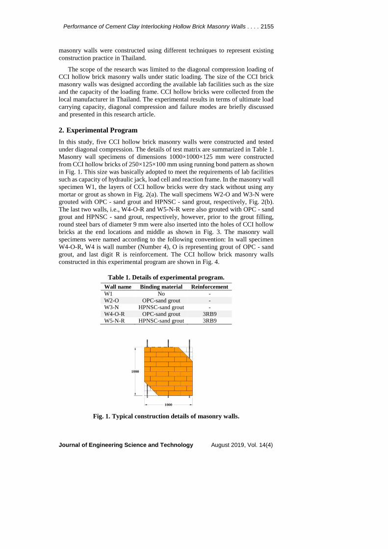
Masonry wall specimens of dimensions 1000×1000×125 mm were constructed
from CCI hollow bricks of 250×125×100 mm using running bond pattern as shown
in Fig. 1. This size was basically adopted to meet the requirements of lab facilities
such as capacity of hydraulic jack, load cell and reaction frame. In the masonry wall
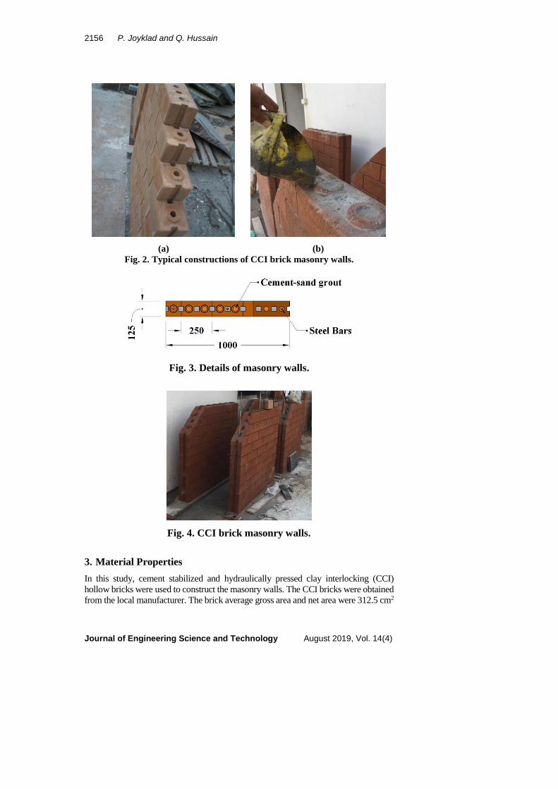
specimen W1, the layers of CCI hollow bricks were dry stack without using any
mortar or grout as shown in Fig. 2(a). The wall specimens W2-O and W3-N were
grouted with OPC - sand grout and HPNSC - sand grout, respectively, Fig. 2(b).
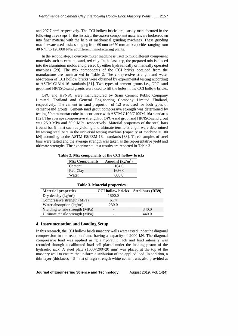
The last two walls, i.e., W4-O-R and W5-N-R were also grouted with OPC - sand
grout and HPNSC - sand grout, respectively, however, prior to the grout filling,
round steel bars of diameter 9 mm were also inserted into the holes of CCI hollow
bricks at the end locations and middle as shown in Fig. 3. The masonry wall
specimens were named according to the following convention: In wall specimen
W4-O-R, W4 is wall number (Number 4), O is representing grout of OPC - sand
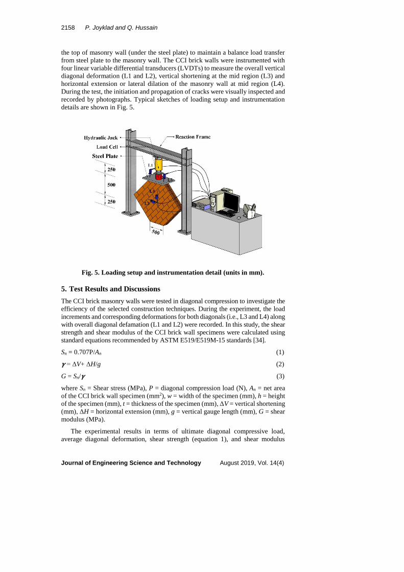
grout, and last digit R is reinforcement. The CCI hollow brick masonry walls
constructed in this experimental program are shown in Fig. 4.
Table 1. Details of experimental program.
Wall name Binding material Reinforcement
W1 No -
W2-O OPC-sand grout -
W3-N HPNSC-sand grout -
W4-O-R OPC-sand grout 3RB9
W5-N-R HPNSC-sand grout 3RB9
Fig. 1. Typical construction details of masonry walls.
2156 P. Joyklad and Q. Hussain
Journal of Engineering Science and Technology August 2019, Vol. 14(4)
(a) (b)
Fig. 2. Typical constructions of CCI brick masonry walls.
Fig. 3. Details of masonry walls.
Fig. 4. CCI brick masonry walls.
3. Material Properties
In this study, cement stabilized and hydraulically pressed clay interlocking (CCI)
hollow bricks were used to construct the masonry walls. The CCI bricks were obtained
from the local manufacturer. The brick average gross area and net area were 312.5 cm2
Performance of Cement Clay Interlocking Hollow Brick Masonry Walls . . . . 2157
Journal of Engineering Science and Technology August 2019, Vol. 14(4)
and 297.7 cm2, respectively. The CCI hollow bricks are usually manufactured in the
following three steps. In the first step, the coarser component materials are broken down
into finer material with the help of mechanical grinding machines. These grinding
machines are used in sizes ranging from 60 mm to 650 mm and capacities ranging from
40 N/hr to 120,000 N/hr at different manufacturing plants.
In the second step, a concrete mixer machine is used to mix different component
materials such as cement, sand, red clay. In the last step, the prepared mix is placed
into the aluminium molds and pressed by either hydraulically or manually operated
machines [29]. The mix components of the CCI bricks obtained from the
manufacture are summarized in Table 2. The compressive strength and water
absorption of CCI hollow bricks were obtained by experimental testing according
to ASTM C1314-16 standards [31]. Two types of cement grouts i.e., OPC-sand
grout and HPNSC-sand grouts were used to fill the holes in the CCI hollow bricks.
OPC and HPNSC were manufactured by Siam Cement Public Company
Limited, Thailand and General Engineering Company Limited Thailand,
respectively. The cement to sand proportion of 1:2 was used for both types of
cement-sand grouts. Cement-sand grout compressive strength was determined by
testing 50 mm mortar cube in accordance with ASTM C109/C109M-16a standards
[32]. The average compressive strength of OPC-sand grout and HPNSC-sand grout
was 25.0 MPa and 50.0 MPa, respectively. Material properties of the steel bars
(round bar 9 mm) such as yielding and ultimate tensile strength were determined
by testing steel bars in the universal testing machine (capacity of machine = 100
kN) according to the ASTM E8/E8M-16a standards [33]. Three samples of steel
bars were tested and the average strength was taken as the representative yield and
ultimate strengths. The experimental test results are reported in Table 3.
Table 2. Mix components of the CCI hollow bricks.
Mix Components Amount (kg/m3)
Cement 164.0
Red Clay 1636.0
Water 600.0
Table 3. Material properties.
Material properties CCI hollow bricks Steel bars (RB9)
Dry density (kg/m3) 1800.0
Compressive strength (MPa) 6.74
Water absorption (kg/m3) 230.0
Yielding tensile strength (MPa) - 340.0
Ultimate tensile strength (MPa) - 440.0
4. Instrumentation and Loading Setup
In this research, the CCI hollow brick masonry walls were tested under the diagonal
compression in the reaction frame having a capacity of 2000 kN. The diagonal
compressive load was applied using a hydraulic jack and load intensity was
recorded through a calibrated load cell placed under the loading piston of the
hydraulic jack. A steel plate (1000×200×20 mm) was placed at the top of the
masonry wall to ensure the uniform distribution of the applied load. In addition, a
thin layer (thickness = 5 mm) of high strength white cement was also provided at
2158 P. Joyklad and Q. Hussain
Journal of Engineering Science and Technology August 2019, Vol. 14(4)
the top of masonry wall (under the steel plate) to maintain a balance load transfer
from steel plate to the masonry wall. The CCI brick walls were instrumented with
four linear variable differential transducers (LVDTs) to measure the overall vertical
diagonal deformation (L1 and L2), vertical shortening at the mid region (L3) and
horizontal extension or lateral dilation of the masonry wall at mid region (L4).
During the test, the initiation and propagation of cracks were visually inspected and
recorded by photographs. Typical sketches of loading setup and instrumentation
details are shown in Fig. 5.
Fig. 5. Loading setup and instrumentation detail (units in mm).
5. Test Results and Discussions
The CCI brick masonry walls were tested in diagonal compression to investigate the
efficiency of the selected construction techniques. During the experiment, the load
increments and corresponding deformations for both diagonals (i.e., L3 and L4) along
with overall diagonal defamation (L1 and L2) were recorded. In this study, the shear
strength and shear modulus of the CCI brick wall specimens were calculated using
standard equations recommended by ASTM E519/E519M-15 standards [34].
Sn = 0.707P/An (1)
𝛄 = ΔV+ ΔH/g (2)
G = Sn/𝛄 (3)
where Sn = Shear stress (MPa), P = diagonal compression load (N), An = net area
of the CCI brick wall specimen (mm2), w = width of the specimen (mm), h = height
of the specimen (mm), t = thickness of the specimen (mm), ΔV = vertical shortening
(mm), ΔH = horizontal extension (mm), g = vertical gauge length (mm), G = shear
modulus (MPa).
The experimental results in terms of ultimate diagonal compressive load,
average diagonal deformation, shear strength (equation 1), and shear modulus
Performance of Cement Clay Interlocking Hollow Brick Masonry Walls . . . . 2159
Journal of Engineering Science and Technology August 2019, Vol. 14(4)
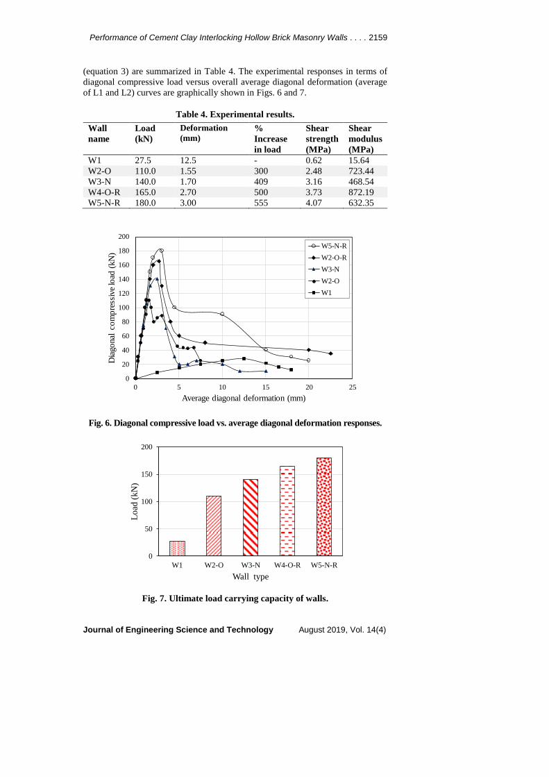
(equation 3) are summarized in Table 4. The experimental responses in terms of
diagonal compressive load versus overall average diagonal deformation (average
of L1 and L2) curves are graphically shown in Figs. 6 and 7.
Table 4. Experimental results.
Wall
name
Load
(kN)
Deformation
(mm) %
Increase
in load
Shear
strength
(MPa)
Shear
modulus
(MPa)
W1 27.5 12.5 - 0.62 15.64
W2-O 110.0 1.55 300 2.48 723.44
W3-N 140.0 1.70 409 3.16 468.54
W4-O-R 165.0 2.70 500 3.73 872.19
W5-N-R 180.0 3.00 555 4.07 632.35
Fig. 6. Diagonal compressive load vs. average diagonal deformation responses.
Fig. 7. Ultimate load carrying capacity of walls.
0
20
40
60
80
100
120
140
160
180
200
0 5 10 15 20 25
Dia
go
nal
co
mp
ress
ive
load
(kN
)
Average diagonal deformation (mm)
W5-N-R
W2-O-R
W3-N
W2-O
W1
0
50
100
150
200
W1 W2-O W3-N W4-O-R W5-N-R
Lo
ad (
kN
)
Wall type
2160 P. Joyklad and Q. Hussain
Journal of Engineering Science and Technology August 2019, Vol. 14(4)
There is a distinct difference between the diagonal compressive load versus
overall average diagonal deformation curves of the masonry walls tested in this
experimental program both in terms of diagonal compressive load and post peak
response. Generally, diagonal compressive load versus diagonal deformation
responses of all the tested CCI brick wall specimens were linear up to the ultimate
diagonal compressive load. Whereas post peak responses were highly influenced
by the presence of cement - sand grout and steel bars. For example, in case of un-
grouted CCI brick masonry wall specimen W1, the post peak response indicates a
very gradual and linear drop in the diagonal load carrying capacity as shown in Fig.
6. Whereas, post peak response of the of the wall specimen W2-O is indicating a
sudden drop in the diagonal load carrying capacity once the ultimate load was
reached. However, the post peak response was not observed truly linear. In case of
wall specimen W3-N, initially linear post peak response was observed until 80%
drop in the load carrying capacity.
In contrast to the un-grouted and unreinforced CCI brick masonry walls, the
post peak responses of the reinforced CCI brick masonry walls were found very
stable with a slight decrease in the load carrying capacity and large axial
deformation as shown in Fig. 6. This phenomenon can be associated with the
presence of steel bars. In the reinforced masonry walls, the steel bars provide
sufficient resistance to the crack widening, propagation and sudden drop in load.
Therefore, the post peak response of the reinforced masonry walls is much stable
as compared with un-reinforced masonry walls.
The un-grouted masonry wall specimen (i.e., W1) was failed at the ultimate load
of 27.50 kN and average diagonal deformation against the ultimate load was 12.5
mm. The final failure of the wall was mainly due to the sliding of the CCI bricks,
splitting and crushing of the CCI hollow bricks. It can be seen (Table 4 and Fig. 6)
that the use of both kinds of grouts (i.e., OPC -sand grout and HPNSC-sand grout)
is very useful to enhance the diagonal load carrying capacity of the both reinforced
and un-reinforced masonry walls. This is because of the reason that the presence of
high strength grout increases the bond strength and interlocking strength of CCI
hollow brick masonry walls.
The masonry wall specimen (W2-O), in which square and circular holes were
filled using OPC -sand grout was reached ultimate load of 110.0 kN, which was
300% higher as compared with the un-grouted CCI hollow brick masonry wall, i.e.,
W1. The increase in ultimate load was mainly due to the cement grout. In this wall
specimen, the diagonal deformation against the ultimate load was recorded as 1.55
mm. The ultimate load carrying capacity and axial deformation of the wall
specimen W3-N were observed as 140.0 kN and 1.70 mm, respectively. The load
carrying capacity of the wall specimen W3-N was recorded 409% and 109% higher
than the wall specimens W1 and W2-O, respectively.
The recorded ultimate load of the wall specimen W3-N was found higher than
the wall specimen W2-O (Table 4). This phenomenon can be associated with the
high compressive strength of HPNSC-sand grout as compared with OPC-sand
grout (see Section 3.0). Previous studies conducted on the diagonal compressive
response of masonry walls had also reported that the shear strength of brick
masonry walls is highly influenced by the strength of bonding mortar and the
compressive strength of the masonry prisms was found higher when using a mortar
with high compressive strength as compared with low strength mortar [35-38].
Performance of Cement Clay Interlocking Hollow Brick Masonry Walls . . . . 2161
Journal of Engineering Science and Technology August 2019, Vol. 14(4)
The diagonal ultimate load carrying capacity and diagonal average deformation
of the wall specimen W4-O-R were recorded as 165.0 kN and 2.70 mm,
respectively. The peak diagonal compressive load was increased by 500% and
200% as compared with wall specimen W1 and W2-O, respectively. The recorded
ultimate load of the wall specimen W5-N-R was 180.0 kN and corresponding axial
deformation was 3.0 mm. Increases of 555% and 146% in the ultimate diagonal
load carrying capacity were observed as compared with wall specimens W1 and
W3-N, respectively.
The ultimate load carrying capacity of reinforced masonry walls is found higher
than the unreinforced masonry walls, which is mainly due to the presence of steel
bars. It is evident from the experimental results that the use of steel bars is very
effective to alter both ultimate load carrying capacity and ultimate failure
mechanism of the CCI brick masonry walls.
The comparison between the un-grouted and grouted CCI brick masonry walls
revels that the use of cement-sand grout and reinforcement increases the shear
strength of wall from 2.48 MPa to 3.16 MPa and shear modulus of 468.53 MPa to
723.44 MPa. The comparison between the un-grouted and reinforced CCI brick
masonry walls revels that the use of steel bars increases the shear strength of wall
from 3.73 MPa to 4.07 MPa and shear modulus from 632.35% to 872.19%.
Only the W1 wall specimens showed lower shear modulus. The higher stiffness
and shear strength belongs to reinforced cement sand grouted CCI brick masonry
walls. The increase in the shear strength as a result of grouting is in line with
findings reported in some previous studies [39] where significant strength increases
were observed when comparing fully grouted and hollow specimens.
6. Cracking and Failure Modes of Masonry Walls
In this section, the cracking pattern and failure modes of the tested masonry walls
are discussed in detail to investigate the efficiency of cement-sand grout and steel
bars to enhance load carrying capacity of CCI brick masonry walls and to alter the
cracking modes of CCI brick masonry walls. The load at the first crack stage is
referred as cracking load in this study. The cracking loads of the tested masonry
walls are summarized in Table 5.
Table 5. Experimental results (cracking load).
Wall name Cracking load (kN) % Increase in cracking load
W1 24 -
W2-O 80 233
W3-N 107 346
W4-O-R 84 250
W5-N-R 114 375
6.1. Masonry wall specimen W1
The CCI brick wall specimen, i.e., W1 was constructed without using any binding
material and or cement-sand and tested under diagonal compression. In this type of
construction, the bond strength is usually achieved through the interlocks of the
CCI hollow bricks. In the wall specimen W1, lateral sliding or extension of the CCI
2162 P. Joyklad and Q. Hussain
Journal of Engineering Science and Technology August 2019, Vol. 14(4)
bricks along the both diagonal planes was observed prior to the development of
cracks in the wall.
The first visible crack (splitting crack) was observed at the diagonal load of
24 kN under the loading region in the mid location. With the further increase in
the load, i.e., at 27 kN, another crack was observed under the loading plate
(slightly towards the right side). As the load was increased, i.e., 29 kN, splitting
cracks were also noticed at the bottom of the wall, as shown in Fig. 7. As the load
was further increased, noticeable sliding of the CCI hollow bricks were observed
along the bed joints.
Initiation of the new cracks on the right side was also observed at the diagonal
load of 39 kN along with further sliding of the CCI bricks. At this stage, a clear gap
of around 1 cm to 2 cm was also noticed between the CCI hollow bricks along the
compression diagonal. With the further increase in the load, widening and
propagation of the existing cracks along with the crushing of the CCI bricks was
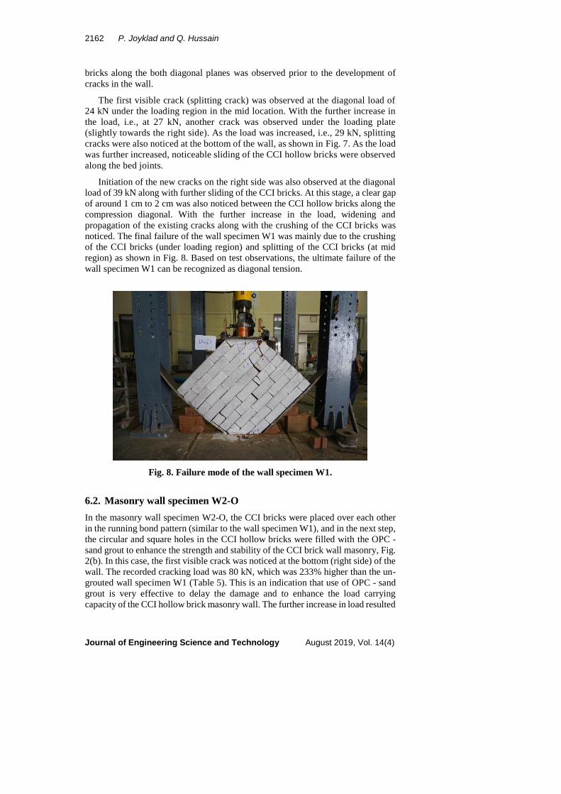
noticed. The final failure of the wall specimen W1 was mainly due to the crushing
of the CCI bricks (under loading region) and splitting of the CCI bricks (at mid
region) as shown in Fig. 8. Based on test observations, the ultimate failure of the
wall specimen W1 can be recognized as diagonal tension.
Fig. 8. Failure mode of the wall specimen W1.
6.2. Masonry wall specimen W2-O
In the masonry wall specimen W2-O, the CCI bricks were placed over each other
in the running bond pattern (similar to the wall specimen W1), and in the next step,
the circular and square holes in the CCI hollow bricks were filled with the OPC -
sand grout to enhance the strength and stability of the CCI brick wall masonry, Fig.
2(b). In this case, the first visible crack was noticed at the bottom (right side) of the
wall. The recorded cracking load was 80 kN, which was 233% higher than the un-
grouted wall specimen W1 (Table 5). This is an indication that use of OPC - sand
grout is very effective to delay the damage and to enhance the load carrying
capacity of the CCI hollow brick masonry wall. The further increase in load resulted
Performance of Cement Clay Interlocking Hollow Brick Masonry Walls . . . . 2163
Journal of Engineering Science and Technology August 2019, Vol. 14(4)
in a sudden and abrupt crack in the mid region along the full height of compressed
diagonal (i.e., from bottom to the loading region).
These cracks were initially observed in the middle region of the compressed
diagonal, then propagating abruptly towards loading region and bottom of the CCI
brick masonry wall. As the load was further increased, i.e., at 84 kN, splitting of
the CCI bricks was also observed at left bottom of the CCI brick masonry wall. The
further increase in the load resulted in the widening and propagation of the existing
vertical cracks in the middle of the wall. The final failure of the wall specimen W2-
O, was mainly due to the splitting of the CCI bricks along the compressed diagonal,
sliding of the CCI brick along the bed joint (at bottom region) and crushing of the
CCI bricks under loading region and at the bottom of the CCI bricks.
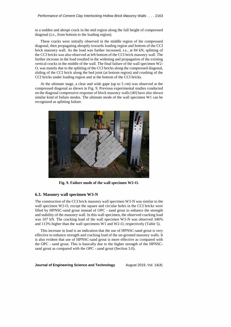
At the ultimate stage, a clear and wide gape (up to 5 cm) was observed at the
compressed diagonal as shown in Fig. 9. Previous experimental studies conducted
on the diagonal compressive response of block masonry walls [40] have also shown
similar kind of failure modes. The ultimate mode of the wall specimen W1 can be
recognized as splitting failure.
Fig. 9. Failure mode of the wall specimen W2-O.
6.3. Masonry wall specimen W3-N
The construction of the CCI brick masonry wall specimen W3-N was similar to the
wall specimen W2-O, except the square and circular holes in the CCI bricks were
filled by HPNSC-sand grout instead of OPC - sand grout to enhance the strength
and stability of the masonry wall. In this wall specimen, the observed cracking load
was 107 kN. The cracking load of the wall specimen W3-N was observed 346%
and 113% higher than the wall specimens W1 and W2-O, respectively (Table 5).
This increase in load is an indication that the use of HPNSC-sand grout is very
effective to enhance strength and cracking load of the un-grouted masonry walls. It
is also evident that use of HPNSC-sand grout is more effective as compared with
the OPC - sand grout. This is basically due to the higher strength of the HPNSC-
sand grout as compared with the OPC - sand grout (Section 3.0).
2164 P. Joyklad and Q. Hussain
Journal of Engineering Science and Technology August 2019, Vol. 14(4)
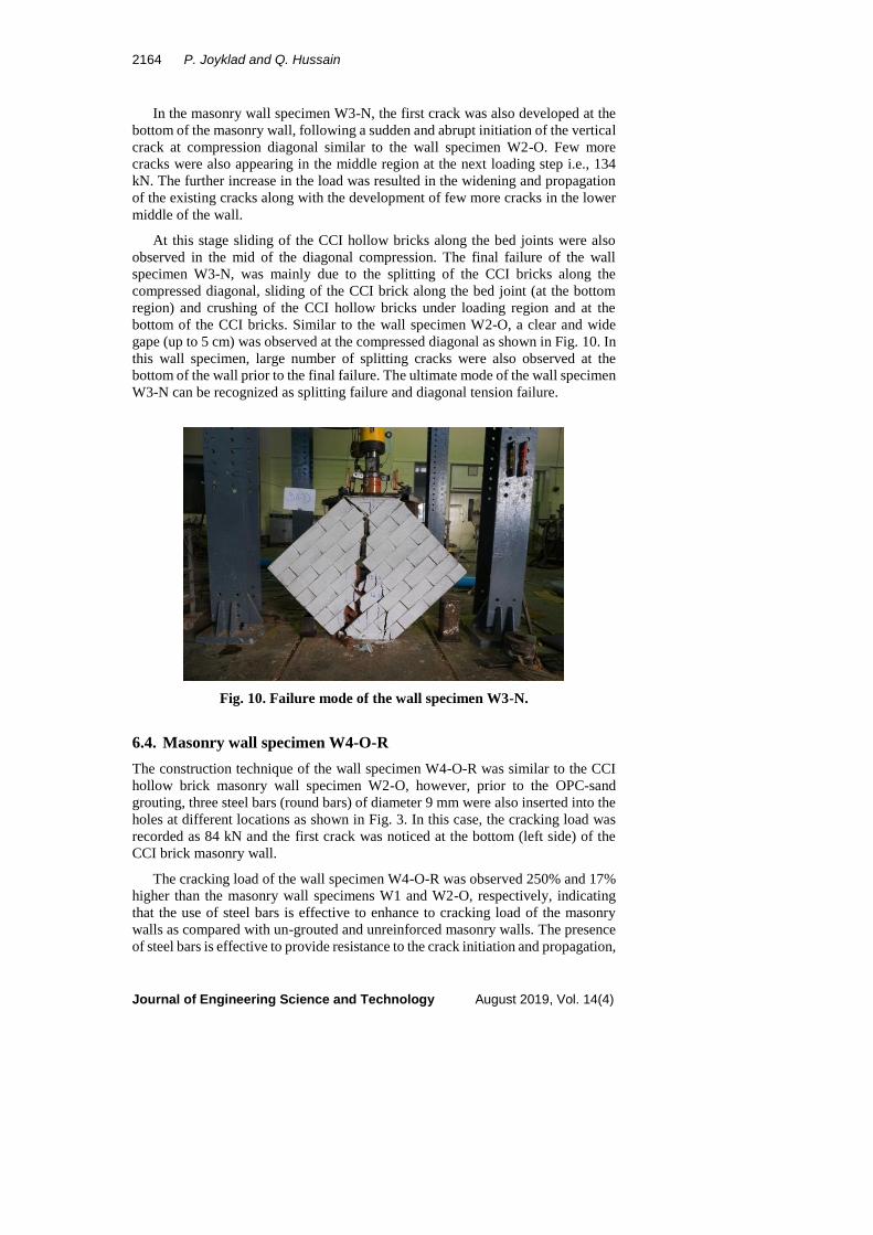
In the masonry wall specimen W3-N, the first crack was also developed at the
bottom of the masonry wall, following a sudden and abrupt initiation of the vertical
crack at compression diagonal similar to the wall specimen W2-O. Few more
cracks were also appearing in the middle region at the next loading step i.e., 134
kN. The further increase in the load was resulted in the widening and propagation
of the existing cracks along with the development of few more cracks in the lower
middle of the wall.
At this stage sliding of the CCI hollow bricks along the bed joints were also
observed in the mid of the diagonal compression. The final failure of the wall
specimen W3-N, was mainly due to the splitting of the CCI bricks along the
compressed diagonal, sliding of the CCI brick along the bed joint (at the bottom
region) and crushing of the CCI hollow bricks under loading region and at the
bottom of the CCI bricks. Similar to the wall specimen W2-O, a clear and wide
gape (up to 5 cm) was observed at the compressed diagonal as shown in Fig. 10. In
this wall specimen, large number of splitting cracks were also observed at the
bottom of the wall prior to the final failure. The ultimate mode of the wall specimen
W3-N can be recognized as splitting failure and diagonal tension failure.
Fig. 10. Failure mode of the wall specimen W3-N.
6.4. Masonry wall specimen W4-O-R
The construction technique of the wall specimen W4-O-R was similar to the CCI
hollow brick masonry wall specimen W2-O, however, prior to the OPC-sand
grouting, three steel bars (round bars) of diameter 9 mm were also inserted into the
holes at different locations as shown in Fig. 3. In this case, the cracking load was
recorded as 84 kN and the first crack was noticed at the bottom (left side) of the
CCI brick masonry wall.
The cracking load of the wall specimen W4-O-R was observed 250% and 17%
higher than the masonry wall specimens W1 and W2-O, respectively, indicating
that the use of steel bars is effective to enhance to cracking load of the masonry
walls as compared with un-grouted and unreinforced masonry walls. The presence
of steel bars is effective to provide resistance to the crack initiation and propagation,
Performance of Cement Clay Interlocking Hollow Brick Masonry Walls . . . . 2165
Journal of Engineering Science and Technology August 2019, Vol. 14(4)
thus resulting in higher load carrying capacity of the masonry walls. Afterward, at
a diagonal load of 110-115 kN, several cracks have formed along the compression
diagonal strip.
The initial formation of these cracks was similar to the un-reinforced CCI brick
masonry walls. However, propagation and widening of these cracks were not
sudden and abrupt as compared with un-reinforced masonry walls. Further
propagation of these cracks towards the bottom and loading region was observed
at the diagonal load of 135-140 kN. This phenomenon (delay in the propagation
and widening of the cracks) is a clear indication that use of steel bars is very
effective to enhance the diagonal load carrying capacity and to delay the cracking
mode of the reinforced CCI hollow brick masonry walls.
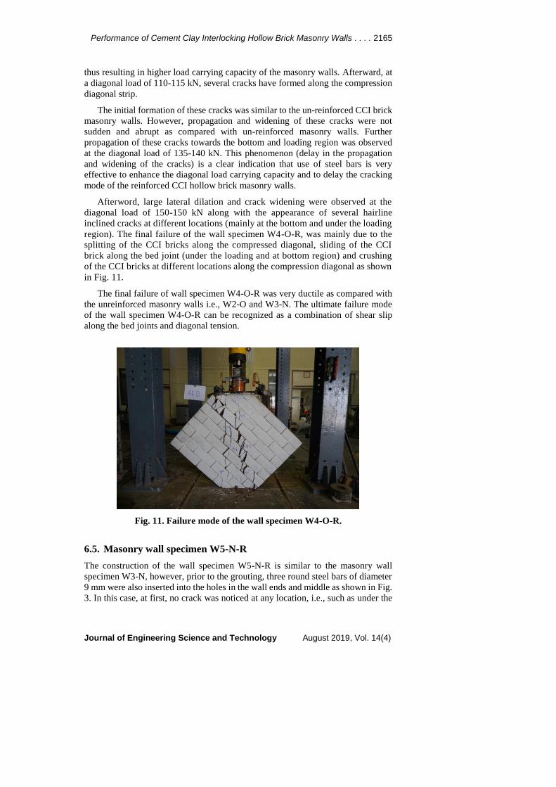
Afterword, large lateral dilation and crack widening were observed at the
diagonal load of 150-150 kN along with the appearance of several hairline
inclined cracks at different locations (mainly at the bottom and under the loading
region). The final failure of the wall specimen W4-O-R, was mainly due to the
splitting of the CCI bricks along the compressed diagonal, sliding of the CCI
brick along the bed joint (under the loading and at bottom region) and crushing
of the CCI bricks at different locations along the compression diagonal as shown
in Fig. 11.
The final failure of wall specimen W4-O-R was very ductile as compared with
the unreinforced masonry walls i.e., W2-O and W3-N. The ultimate failure mode
of the wall specimen W4-O-R can be recognized as a combination of shear slip
along the bed joints and diagonal tension.
Fig. 11. Failure mode of the wall specimen W4-O-R.
6.5. Masonry wall specimen W5-N-R
The construction of the wall specimen W5-N-R is similar to the masonry wall
specimen W3-N, however, prior to the grouting, three round steel bars of diameter
9 mm were also inserted into the holes in the wall ends and middle as shown in Fig.
3. In this case, at first, no crack was noticed at any location, i.e., such as under the
2166 P. Joyklad and Q. Hussain
Journal of Engineering Science and Technology August 2019, Vol. 14(4)
loading region and at bottom of the wall. Then the main crack initiates at
compression diagonal similar to the other cement-sand grouted masonry wall
specimen and the observed cracking load was 114 kN.
The cracking load of the wall specimen W5-N-R was observed 375% and 29%
higher than the masonry wall specimens W1 and W3-N, respectively, indicating
that the use of steel bars is effective to enhance the cracking load of the masonry
walls as compared with un-grouted and unreinforced masonry walls. The presence
of steel bars is effective to provide resistance to the crack initiation and propagation,
thus resulting in higher load carrying capacity of the masonry walls. Afterward,
propagation of the main crack towards the loading region was observed at diagonal
load 116-120 kN.
As the load was further increased, i.e., at 124 kN, the propagation of the main
crack was also observed towards the bottom region of the masonry wall. The
further increase in the load was resulted in the widening and propagation of the
existing cracks along with the development of few more cracks in the lower
middle of the wall. Similar to the wall specimen W4-O-R, there was found delay
in the crack widening and propagation after the development of initial cracks
due to the presence of steel bars. Afterword, large lateral dilation and crack
widening were observed at the diagonal load of 150-150 kN along with the
appearance of several hairline inclined cracks at different locations (mainly at the
bottom location).
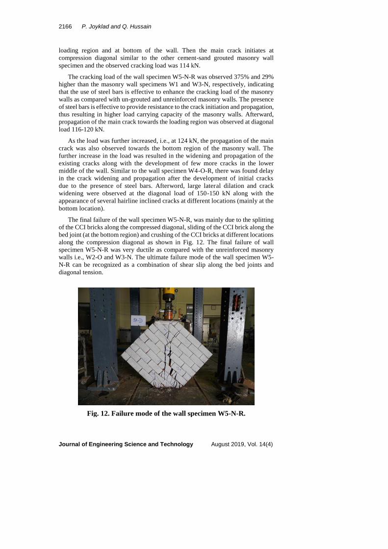
The final failure of the wall specimen W5-N-R, was mainly due to the splitting
of the CCI bricks along the compressed diagonal, sliding of the CCI brick along the
bed joint (at the bottom region) and crushing of the CCI bricks at different locations
along the compression diagonal as shown in Fig. 12. The final failure of wall
specimen W5-N-R was very ductile as compared with the unreinforced masonry
walls i.e., W2-O and W3-N. The ultimate failure mode of the wall specimen W5-
N-R can be recognized as a combination of shear slip along the bed joints and
diagonal tension.
Fig. 12. Failure mode of the wall specimen W5-N-R.
Performance of Cement Clay Interlocking Hollow Brick Masonry Walls . . . . 2167
Journal of Engineering Science and Technology August 2019, Vol. 14(4)
7. Conclusions
This study presents a comprehensive investigation on the efficiency of cement -sand
grouts and steel bars for cement-clay interlocking (CCI) hollow brick masonry walls
to enhance the load carrying capacity and to alter the failure modes of the CCI hollow
brick masonry walls. An experimental program was established and five CCI hollow
brick masonry walls were tested under diagonal compression. Two types of cement
sand grouts i.e., OPC - sand grout and HPNSC -sand grout were used along with steel
bars. From the conducted tests, the following conclusion can be drawn;
The un-grouted masonry wall fails in a ductile manner with a large vertical and
horizontal deformation.
The grouted masonry walls (unreinforced masonry walls) in which square and
circular holes in the CCI hollow bricks were filled by cement grouts resulted
in higher ultimate load carrying capacity, shear strength and shear modulus as
compared with un-grouted masonry wall. In general, increasing the grout
strength results in increasing the ultimate load carrying capacity of the CCI
hollow brick masonry walls. The ultimate failure of the cement-sand grouted
masonry walls was observed brittle and sudden.
In contrast to the unreinforced masonry walls, the overall response of the steel
reinforced masonry walls was found significantly improving in terms of diagonal
load carrying capacity, shear strength, shear modulus and ultimate failure modes.
Probably the most obvious suggestion for continued research into CCI
hollow brick masonry walls is to the investigate the seismic response of CCI
hollow brick masonry walls under lateral loading to simulate the effect of
earthquake loading.
Acknowledgement
The authors are very grateful to the Faculty of Engineering, Srinakharinwirot
University, Thailand, for providing research grant (Research Grant ID 568/2560)
to carry out the research work. The authors are also very thankful to the Asian
Institute of Technology (AIT) for supporting test facilities.
Nomenclatures
An Net area of the wall, mm2
G Shear modulus, MPa
g Vertical gauge length, mm
h Height of the specimen, mm
P Diagonal compression load, N
Sn Shear stress, MPa
t Thickness of the specimen, mm
w Width of the specimen, mm
Abbreviations
ASTM
CCI
American Society for Testing and Materials
Cement-Clay Interlocking
ICEBs Interlocking Compressed Earth Blocks
RB Round Bars
2168 P. Joyklad and Q. Hussain
Journal of Engineering Science and Technology August 2019, Vol. 14(4)
References
1 Thaickavil, N.N.; and Thomas, J. (2018). Behaviour and strength assessment
of masonry prisms. Case Studies in Construction Materials, 8, 23-38.
2 Turnšek, V.; and Čačovič, F. (1971). Some experimental results on the strength
of brick masonry walls. Proceedings of the Second International Brick
Masonry Conference. Stoke-on-Trent, United Kingdom, 149-156.
3 Kent, D.C.; and Park, R. (1971). Flexural members with confined concrete.
Journal of the Structural Division, 97(7), 1969-1990.
4 Calvi, G.M.; and Magenes, G. (1991). Experimental evaluation of seismic
strength of old masonry structures. Proceedings of 9th International
Brick/Block Masonry Conference. Berlin, Gemany, 490-497.
5 Naraine, K.; and Sinha, S. (1989). Behavior of brick masonry under cyclic
compressive loading. Journal of Structural Engineering, 115(6), 1432-1445.
6 Augenti, N.; and Parisi, F. (2010). Constitutive models for tuff masonry
under uniaxial compression. Journal of Materials in Civil Engineering,
22(11), 1102-1111.
7 Parisi, F.; and Augenti, N. (2013). Assessment of unreinforced masonry cross
sections under eccentric compression accounting for strain softening.
Construction and Building Materials, 41, 654-664.
8 Li, J.; Masia, M.J.; Stewart, M.G.; and Lawrence, S.J. (2014). Spatial
variability and stochastic strength prediction of unreinforced masonry walls in
vertical bending. Engineering Structures, 59, 787-797.
9 Zavalis, R.; Jonaitis, B.; and Marčiukaitis, G. (2013). Numerical and
experimental analysis of grouted hollow block masonry under compression.
Engineering Structures and Technologies, 5(2), 45-53.
10 Lin, K.; Totoev, Y.Z.; Liu, H.; and Wei, C. (2015). Experimental
characteristics of dry stack masonry under compression and shear loading.
Materials, 8(12), 8731-8744.
11 Faella, C.; Martinelli, E.; Paciello, S.; Camorani, G.; Aiello, M.A.; Micelli, F.;
and Nigro, E. (2011). Masonry columns confined by composite materials:
Experimental investigation. Composites Part B: Engineering, 42(4), 692-704.
12 Mazzotti, C.; Ferracuti, B.; and Bellini, A. (2015). Experimental bond tests on
masonry panels strengthened by FRP. Composites Part B: Engineering, 80,
223-237.
13 Micelli, F.; Ludovico, M.D.; Balsamo, A.; and Manfredi, G. (2018).
Mechanical behaviour of FRP-confined masonry by testing of full-scale
columns. Materials and Structures, 47(12), 2081-2100.
14 Miccoli, L.; Müller, U.; and Fontana, P. (2014). Mechanical behaviour of
earthen materials: a comparison between earth block masonry, rammed earth
and cob. Construction and Building Materials, 61, 327-339.
15 Gurumo, S.R. (1992). Diagonal compression strength of adobe wall panels.
Master of Engineering Project D Report. University of Auckland, Auckland,
New Zealand.
16 Sathiparan, N.; Mayorca, P.; Nashelli, K.N.; Guragain, R.; and Meguro, K.
(2006). Experimental study on unburned brick masonry wallettes retrofitted by
pp-band meshes. Seisan Kenkyu, 58(3), 301-304.
Performance of Cement Clay Interlocking Hollow Brick Masonry Walls . . . . 2169
Journal of Engineering Science and Technology August 2019, Vol. 14(4)
17 Bartolomé, A.S.; Delgado, E.; and Quiun, D. (2009). Seismic behaviour of a
two-story model of confined adobe masonry. Proceedings of 11th Canadian
Masonry Symposium. Toronto, Ontario, 10 pages.
18 Alecci, V.; Fagone, M.; Rotunno, T.; and De Stefano, M. (2013). Shear
strength of brick masonry walls assembled with different types of mortar.
Construction and Building Materials, 40, 1038-1045.
19 Yardim, Y.; and Lalaj, O. (2016). Shear strengthening of unreinforced masonry
wall with different fiber reinforced mortar jacketing. Construction and
Building Materials, 102(Part 1), 149-154.
20 Nazar, M.E.; and Sinha, S.N. (2006). Influence of bed joint orientation on
interlocking grouted stabilized mud-fly ash brick masonry under cyclic
compressive loading. Structural Engineering and Mechanics, 24(5), 585-599.
21 Nazar, M.E.; and Sinha, S.N. (2007). Behavior of interlocking grouted
stabilized sand-fly ash brick masonry under uniaxial cyclic compressive
loading. Journal of Materials in Civil Engineering, 19(11), 947-956.
22 Ronoh, V.; Too, J.K.; Kaluli, J.W.; and Victor, R.; (2014). Cement effects on
the physical properties of expansive clay soil and the compressive strength of
compressed interlocking clay blocks. European International Journal of
Science and Technology, 3(8), 74-82.
23 Laursen, P.T.; Herskedal, N.A.; Jansen, D.C.; and Qu, B. (2015). Out-of-plane
structural response of interlocking compressed earth block walls. Materials
and Structures, 48(1-2), 321-336.
24 Bland, D.W. (2011). In-plane cyclic shear performance of interlocking
compressed earth block walls. Master Thesis. Faculty of California
Polytechnic State University, San Luis Obispo, California.
25 Namboonruang, W.; Rawangkul, R.; Yodsudjai, W.; and Khedari, J. (2011).
Investigation of properties of low thermal conductivity pozzolanics soil bricks
towards sustainable development. Advanced Materials Research, 261-263,
469-479.
26 Namboonruang, W.; Rawangkul, R.; and Yodsudjai, W. (2012). Strength
properties of low thermal conductivity fly ash bricks: compressive and flexural
strength aspects. Applied Mechanics and Materials, 117-119, 1352-1357.
27 Yoosathaporn, S.; Tiangburanatham, P.; and Pathom-aree, W. (2015). The
influence of biocalcification on soil-cement interlocking block compressive
strength. Biotechnologie, Agronomie, Société et Environnement, 19(3), 262-269.
28 Namboonruang, W.; Rawangkul, R.; and Yodsudjai, W. (2013). A perspective
study on strength properties-low thermal conductivity and leachability of
pozzolanics soil bricks towards to environmentally friendly. Advanced Science
Letters, 19(10), 2831-2841.
29 Joyklad, P. (2018). Mechanical properties of local cement-clay interlocking
bricks in central part of Thailand. SWU Engineering Journal, 13(1), 1-12.
30 Shakir, A.A.; and Mohammed, A.A. (2015). Durability property of clay ash,
quarry dust and billet scale bricks. Journal of Engineering Science and
Technology (JESTEC), 10(5), 591-605.
31 ASTM International. (2016). Standard test method for compressive strength of
masonry prisms. ASTM C1314-16.
2170 P. Joyklad and Q. Hussain
Journal of Engineering Science and Technology August 2019, Vol. 14(4)
32 ASTM International (2016). Standard test method for compressive strength of
hydraulic cement mortars (using 2-in. or [50-mm] cube specimens). ASTM
C109/C109M-16a.
33 ASTM International. (2016). Standard test methods for tension testing of
metallic materials. ASTM E8/E8M-16a.
34 ASTM International. (2015). Standard test method for diagonal tension (shear)
in masonry assemblages. ASTM E519/E519M-15.
35 Freeda Christy, C.; Tensing, D.; and Mercy Shanthi, R. (2013). Experimental
study on axial compressive strength and elastic modulus of the clay and fly ash
brick masonry. Journal of Civil Engineering and Construction Technology,
4(4), 134-141.
36 Barbosa, C.S.; Lourenço, P.B.; and Hanai, J.B. (2010). On the compressive
strength prediction for concrete masonry prisms. Materials and Structures,
43(3), 331-344.
37 Khalaf, F.M.; Hendry, A.W.; and Fairbairn, D.R. (1994). Study of the
compressive strength of blockwork masonry. Structural Journal, 91(4), 367-375.
38 McNary, W.S.; and Abrams, D.P. (1985). Mechanics of masonry in
compression. Journal of Structural Engineering, 111(4), 857-870.
39 Drysdale, R.G.; and Hamid, A. A. (1979). Behavior of concrete block masonry
under axial compression. American Concrete Institute Journal, 76(6), 707-721.
40 Kaaki, T. (2013). Behavior and strength of masonry prisms loaded in
compression. Master Thesis. Dalhousie University Halifax, Halifax, Nova
Scotia, Canada.