Embed Size (px)
Citation preview

- 1 -
PERFORMANCE OF DOUBLE-T PRESTRESSED CONCRETE BEAMS STRENGTHENED WITH
STEEL REINFORCED POLYMER
By Paolo Casadei, Antonio Nanni, Tarek Alkhrdaji and Jay Thomas
Synopsis In the fall of 2002, a two story parking garage in Bloomington, Indiana, built with precast prestrestressed concrete (PC) double-T beams, was decommissioned due to a need for increased parking-space. This led to the opportunity of investigating the flexural per-formance of the PC double-T beams, upgraded in the positive moment region with steel reinforced polymer (SRP) composite materials, representing the first case study where this material has been applied in the field. SRP makes use of high-strength steel cords embedded in an epoxy resin. This paper reports on the test results to failure of three beams: a control specimen, a beam strengthened with one ply of SRP and a third beam strengthened with two plies of SRP anchored at both ends with SRP U-wraps. Results showed that SRP can significantly improve both flexural capacity and enhance pseudo-ductility. Keywords: double-T beams; ductility; flexure; in-situ load test; prestressed concrete;
steel reinforced polymer; strengthening.
- 2 -
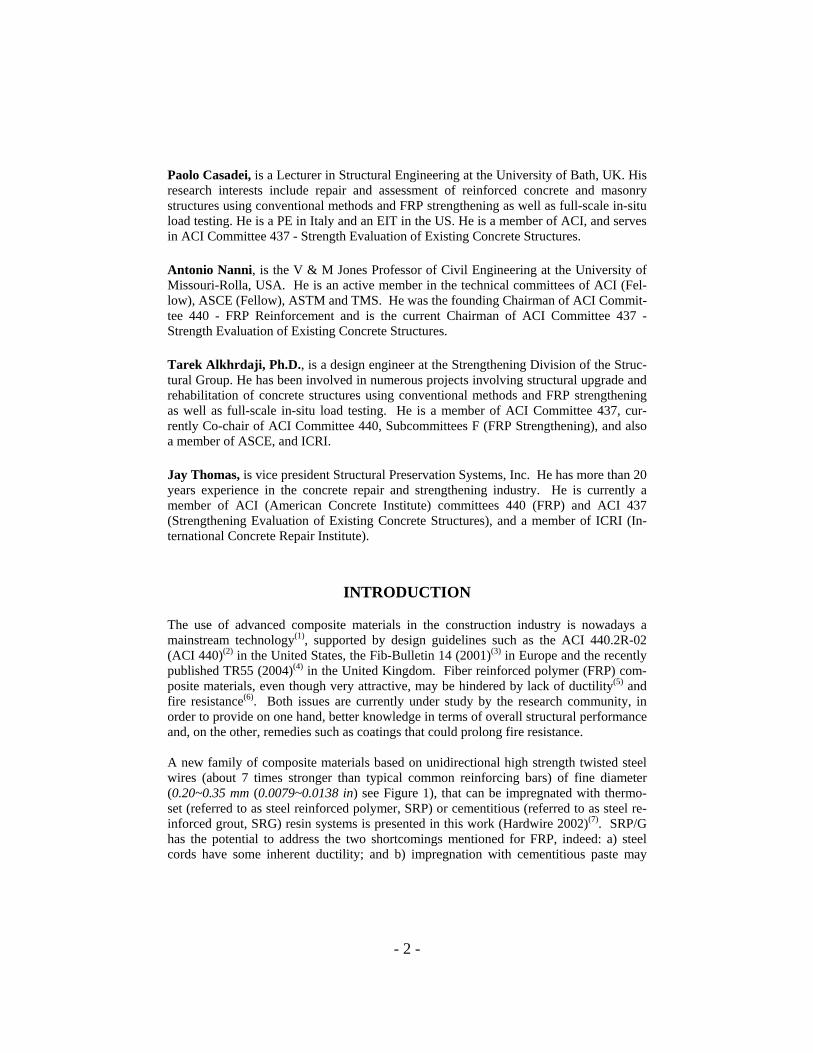
Paolo Casadei, is a Lecturer in Structural Engineering at the University of Bath, UK. His research interests include repair and assessment of reinforced concrete and masonry structures using conventional methods and FRP strengthening as well as full-scale in-situ load testing. He is a PE in Italy and an EIT in the US. He is a member of ACI, and serves in ACI Committee 437 - Strength Evaluation of Existing Concrete Structures. Antonio Nanni, is the V & M Jones Professor of Civil Engineering at the University of Missouri-Rolla, USA. He is an active member in the technical committees of ACI (Fel-low), ASCE (Fellow), ASTM and TMS. He was the founding Chairman of ACI Commit-tee 440 - FRP Reinforcement and is the current Chairman of ACI Committee 437 - Strength Evaluation of Existing Concrete Structures. Tarek Alkhrdaji, Ph.D., is a design engineer at the Strengthening Division of the Struc-tural Group. He has been involved in numerous projects involving structural upgrade and rehabilitation of concrete structures using conventional methods and FRP strengthening as well as full-scale in-situ load testing. He is a member of ACI Committee 437, cur-rently Co-chair of ACI Committee 440, Subcommittees F (FRP Strengthening), and also a member of ASCE, and ICRI. Jay Thomas, is vice president Structural Preservation Systems, Inc. He has more than 20 years experience in the concrete repair and strengthening industry. He is currently a member of ACI (American Concrete Institute) committees 440 (FRP) and ACI 437 (Strengthening Evaluation of Existing Concrete Structures), and a member of ICRI (In-ternational Concrete Repair Institute).
INTRODUCTION
The use of advanced composite materials in the construction industry is nowadays a mainstream technology(1), supported by design guidelines such as the ACI 440.2R-02 (ACI 440)(2) in the United States, the Fib-Bulletin 14 (2001)(3) in Europe and the recently published TR55 (2004)(4) in the United Kingdom. Fiber reinforced polymer (FRP) com-posite materials, even though very attractive, may be hindered by lack of ductility(5) and fire resistance(6). Both issues are currently under study by the research community, in order to provide on one hand, better knowledge in terms of overall structural performance and, on the other, remedies such as coatings that could prolong fire resistance. A new family of composite materials based on unidirectional high strength twisted steel wires (about 7 times stronger than typical common reinforcing bars) of fine diameter (0.20~0.35 mm (0.0079~0.0138 in) see Figure 1), that can be impregnated with thermo-set (referred to as steel reinforced polymer, SRP) or cementitious (referred to as steel re-inforced grout, SRG) resin systems is presented in this work (Hardwire 2002)(7). SRP/G has the potential to address the two shortcomings mentioned for FRP, indeed: a) steel cords have some inherent ductility; and b) impregnation with cementitious paste may
- 3 -
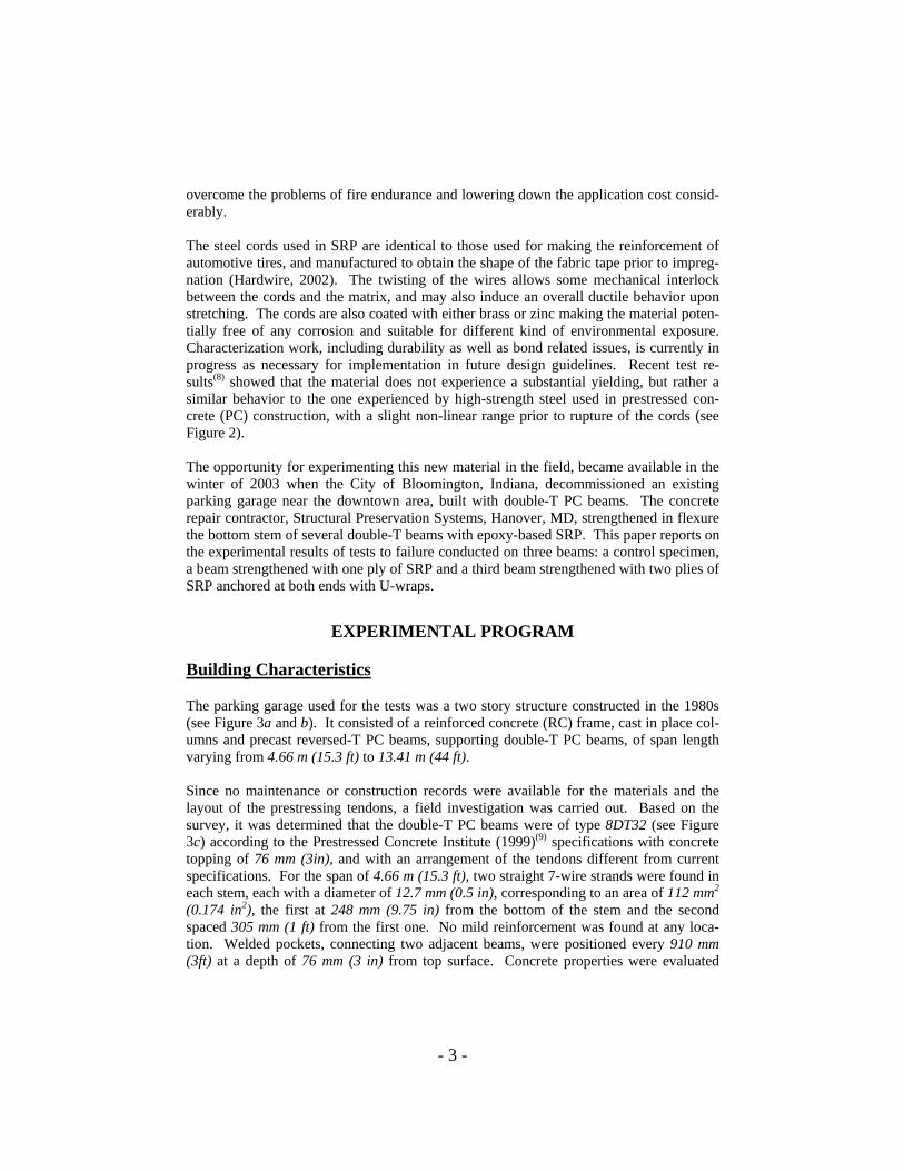
overcome the problems of fire endurance and lowering down the application cost consid-erably. The steel cords used in SRP are identical to those used for making the reinforcement of automotive tires, and manufactured to obtain the shape of the fabric tape prior to impreg-nation (Hardwire, 2002). The twisting of the wires allows some mechanical interlock between the cords and the matrix, and may also induce an overall ductile behavior upon stretching. The cords are also coated with either brass or zinc making the material poten-tially free of any corrosion and suitable for different kind of environmental exposure. Characterization work, including durability as well as bond related issues, is currently in progress as necessary for implementation in future design guidelines. Recent test re-sults(8) showed that the material does not experience a substantial yielding, but rather a similar behavior to the one experienced by high-strength steel used in prestressed con-crete (PC) construction, with a slight non-linear range prior to rupture of the cords (see Figure 2).
The opportunity for experimenting this new material in the field, became available in the winter of 2003 when the City of Bloomington, Indiana, decommissioned an existing parking garage near the downtown area, built with double-T PC beams. The concrete repair contractor, Structural Preservation Systems, Hanover, MD, strengthened in flexure the bottom stem of several double-T beams with epoxy-based SRP. This paper reports on the experimental results of tests to failure conducted on three beams: a control specimen, a beam strengthened with one ply of SRP and a third beam strengthened with two plies of SRP anchored at both ends with U-wraps.
EXPERIMENTAL PROGRAM
Building Characteristics
The parking garage used for the tests was a two story structure constructed in the 1980s (see Figure 3a and b). It consisted of a reinforced concrete (RC) frame, cast in place col-umns and precast reversed-T PC beams, supporting double-T PC beams, of span length varying from 4.66 m (15.3 ft) to 13.41 m (44 ft). Since no maintenance or construction records were available for the materials and the layout of the prestressing tendons, a field investigation was carried out. Based on the survey, it was determined that the double-T PC beams were of type 8DT32 (see Figure 3c) according to the Prestressed Concrete Institute (1999)(9) specifications with concrete topping of 76 mm (3in), and with an arrangement of the tendons different from current specifications. For the span of 4.66 m (15.3 ft), two straight 7-wire strands were found in each stem, each with a diameter of 12.7 mm (0.5 in), corresponding to an area of 112 mm2 (0.174 in2), the first at 248 mm (9.75 in) from the bottom of the stem and the second spaced 305 mm (1 ft) from the first one. No mild reinforcement was found at any loca-tion. Welded pockets, connecting two adjacent beams, were positioned every 910 mm (3ft) at a depth of 76 mm (3 in) from top surface. Concrete properties were evaluated

- 4 -
using three cores taken from three different beams at the location of the stem and an ava-rage concrete cylinder strength of fc’=34 N/mm2 (fc’=5000 psi) was found and its mod-ulus of elasticity was determined according to ACI 318-02 Section 8.5.1(10) provisions. The strands properties were assumed to be conventional 1861 MPa (270 ksi) strength. Table 1 summarizes construction material properties.
Specimens and Installation of Steel Reinforced Polymer
A total of three double-T PC beams were tested (see Figure 4a and b): beam DT-C is the control beam, beam DT-1 represents the beam strengthened with one ply of SRP and DT-2U the one strengthened with 2 plies of SRP anchored with SRP U-wraps. Figure 4c illustrates the strengthening geometry details for beam DT-1 and DT-2U. The epoxy resin for both strengthened beams was SikaDur Resin 330(11). The choice of the resin was based on constructability so that it could be rolled onto the surface for over-head applications, while having enough consistency, even before curing, to be able to hold the weight of the steel tape during cure. Table 2 reports the resin properties supplied by the manufacturer and verified by testing according to ASTM standards by Huang et al. 2004(8). Figure 5a shows the mixing of the resin prior to installation. The tape was medium density consisting of 6.3 cords per cm (12 WPI), with material properties defined in Table 3. The typical stress-strain diagram for an impregnated me-dium density tape, tested following the ASTM D 3039(12) recommendations, is reported in Figure 2 (properties based on steel net area). SRP was installed following the recommendations of ACI 440(2) provisions for FRP ma-terials. The sequence of installation steps is reported in Figure 5. The bottom stem of the double-T beams was first abrasive-blasted to ensure proper bond of the SRP system. With the surface roughened and cleaned, the first layer of epoxy was directly applied (see Figure 5b), without primer coating. The steel tape was cut to length of 4.57 m (15 ft) and width of 102 mm (4 in), covering the bottom of the stem length and width entirely. A rib-roller was then utilized to press onto the tape to ensure epoxy impregnation and encapsu-lation of each cord and allow excess resin to squeeze out. The excess resin was spread with a putty-knife to create an even surface (see Figure 5c) and a synthetic scrim was applied to avoid any dripping of the resin (see Figure 5d). For the two ply application, once the first ply was in place and the excess resin leveled, the second ply was installed, following an identical procedure. This time the ply started 152 mm (6 in) away from the terminations of the first ply, making it 4.27 m (14 ft) long. To provide a mechanical an-corage for the two longitudinal plies, an SRP U-wrap 914 mm (3 ft) wide was installed at both ends of the stems (see Figure 5e). Due to the stiffness of the steel tape, pre-forming is done with a standard sheet metal bender before installation. For this reason, the U-wrap was obtained by overlapping two L-shaped wraps. A final coat of epoxy resin was then applied on top of the U-wrap as final layer to impregnate the tape (see Figure 5f).
- 5 -
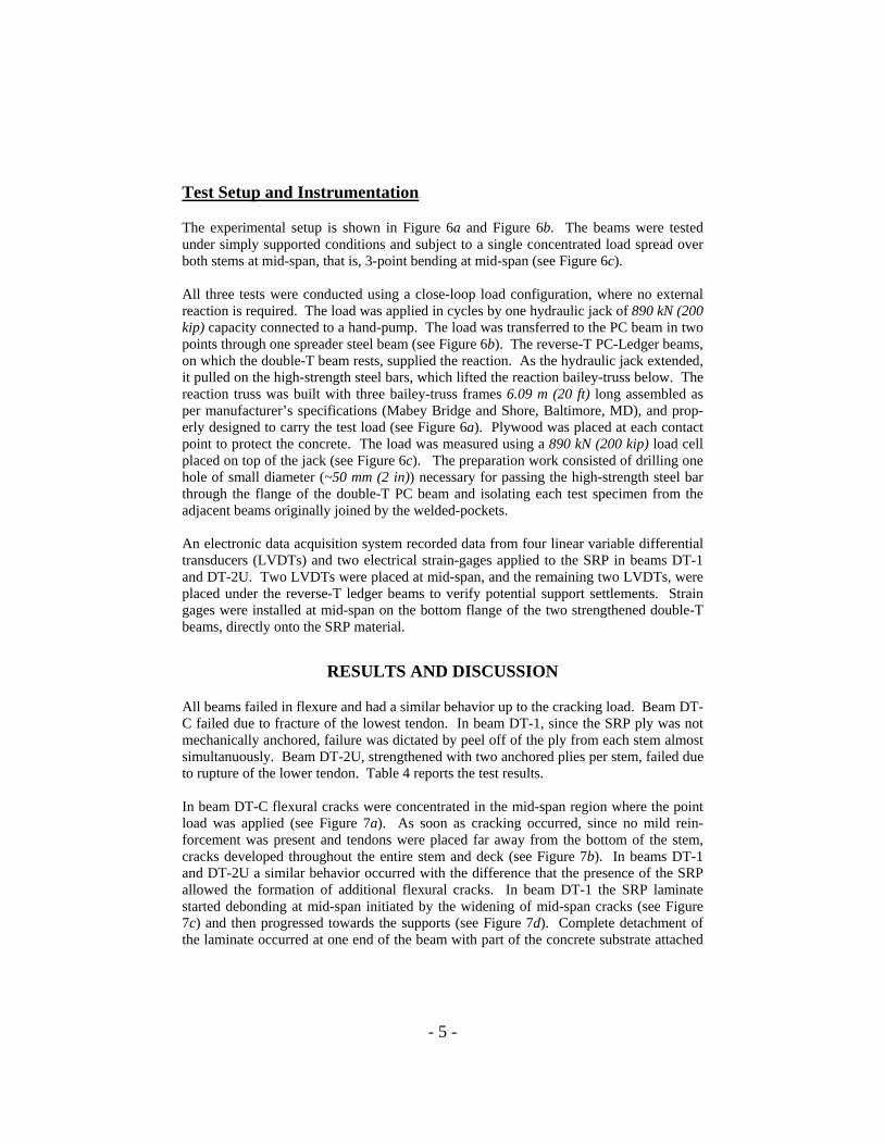
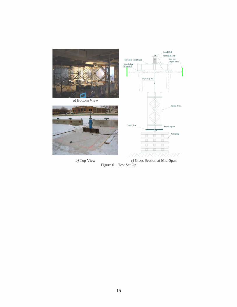
Test Setup and Instrumentation
The experimental setup is shown in Figure 6a and Figure 6b. The beams were tested under simply supported conditions and subject to a single concentrated load spread over both stems at mid-span, that is, 3-point bending at mid-span (see Figure 6c). All three tests were conducted using a close-loop load configuration, where no external reaction is required. The load was applied in cycles by one hydraulic jack of 890 kN (200 kip) capacity connected to a hand-pump. The load was transferred to the PC beam in two points through one spreader steel beam (see Figure 6b). The reverse-T PC-Ledger beams, on which the double-T beam rests, supplied the reaction. As the hydraulic jack extended, it pulled on the high-strength steel bars, which lifted the reaction bailey-truss below. The reaction truss was built with three bailey-truss frames 6.09 m (20 ft) long assembled as per manufacturer’s specifications (Mabey Bridge and Shore, Baltimore, MD), and prop-erly designed to carry the test load (see Figure 6a). Plywood was placed at each contact point to protect the concrete. The load was measured using a 890 kN (200 kip) load cell placed on top of the jack (see Figure 6c). The preparation work consisted of drilling one hole of small diameter (~50 mm (2 in)) necessary for passing the high-strength steel bar through the flange of the double-T PC beam and isolating each test specimen from the adjacent beams originally joined by the welded-pockets. An electronic data acquisition system recorded data from four linear variable differential transducers (LVDTs) and two electrical strain-gages applied to the SRP in beams DT-1 and DT-2U. Two LVDTs were placed at mid-span, and the remaining two LVDTs, were placed under the reverse-T ledger beams to verify potential support settlements. Strain gages were installed at mid-span on the bottom flange of the two strengthened double-T beams, directly onto the SRP material.
RESULTS AND DISCUSSION
All beams failed in flexure and had a similar behavior up to the cracking load. Beam DT-C failed due to fracture of the lowest tendon. In beam DT-1, since the SRP ply was not mechanically anchored, failure was dictated by peel off of the ply from each stem almost simultanuously. Beam DT-2U, strengthened with two anchored plies per stem, failed due to rupture of the lower tendon. Table 4 reports the test results. In beam DT-C flexural cracks were concentrated in the mid-span region where the point load was applied (see Figure 7a). As soon as cracking occurred, since no mild rein-forcement was present and tendons were placed far away from the bottom of the stem, cracks developed throughout the entire stem and deck (see Figure 7b). In beams DT-1 and DT-2U a similar behavior occurred with the difference that the presence of the SRP allowed the formation of additional flexural cracks. In beam DT-1 the SRP laminate started debonding at mid-span initiated by the widening of mid-span cracks (see Figure 7c) and then progressed towards the supports (see Figure 7d). Complete detachment of the laminate occurred at one end of the beam with part of the concrete substrate attached

- 6 -
to the laminate, denoting a good interface bond between the concrete and the SRP (see Figure 8a and b). In beam DT-2, SRP could not completely peel off due to the presence of U-wraps. Delamination propagated from mid-span towards the supports similarly to Beam DT-1, until rupture of the lower tendon occurred (see Figure 7e) and immediately followed by SRP rupture exactly at the location where the SRP U-wrap started (see Figure 7f). No shear cracks were noted on any of the three beams. Figure 9 shows the Load-vs-mid-pan Deflection curves for all three beams. The capaci-ties of beams DT-1 and DT-2U increased approximately 12% and 26% with respect to the control specimen DT-C. Figure 10 report the Load-vs-Mid-Span Strain responses for beams DT-1 and DT-2U. Two distinct phases, pre- and post-cracking, characterize the behavior of each specimen. Up to cracking there was practically no strain in the SRP. Past the cracking load, the presence of the SRP significantly affected performance. Beam DT-C cracked at a considerably lower load (250.8 kN (56.4 kip)), with respect to the other two strengthened specimens. The occurrence of the first crack, at mid-span only, corresponds to the load drop in the Load-vs-Displacement plot. Upon unloading, the beam remained almost perfectly elastic, recovering almost all deflection. At the third loading cycle the lower strand suddenly fractured at a load of 344.3 kN (77.4 kip). For beams DT-1 and DT-2U the cracking load increased of approximately 23% and 17% with respect to DT-C. The lower cracking load for DT-2U may be explained by the fact that the beam had been previously repaired by means of epoxy injection. Beam DT-1 reached the peak load of 387 kN (87 kip) and held it constant with increasing deflection, while SRP progressively delaminated from mid-span towards the support. The strain profile reported in Figure 10 shows how the SRP was not engaged until crack-ing occurred and as soon as the first crack opened at mid-span, the SRP bridged the crack and strain suddenly increased to approximately 5500 µε (strain-gauge was placed at mid span where the first crack occurred). The maximum strain recorded in the steel tape (12300 µε), prior to complete peel-off, shows how the material was well bonded to the concrete substrate. The ductility reported in the load-deflection curve, is the result of the slow peeling propagation rather than to the yielding of the reinforcing steel tape itself. Figure 2 shows in fact an almost elastic behavior till rupture of the SRP laminate. Past the cracking load (see Figure 10), beam DT-2U behaved almost linearly, although with a lower stiffness, until it reached the load of 400 kN (90 kip) then, stiffness de-creased significantly till the peak load was reached. When the load of 434 kN (97.6 kip) was reached, the lower tendon ruptured and a sudden drop in the load-deflection curve was recorded. The strain in the SRP material at time which the tendon ruptured was 6400 µε. At this stage, once the lower tendon ruptured, the SRP laminate was completely debonded except for the region where anhoring was provided by the U-wraps. The test was continued untill suddenly the SRP laminate ruptured at 388 kN (87.2 kip). The strain recorded in the SRP laminate at failure was 12000 µε, similarly the values attained in beam DT-1.

- 7 -
CONCLUSIONS
The following conclusions may be drawn from this experimental program: • SRP composite materials have shown to be effective in increasing the flexural capac-
ity of the double-T PC beams. • End anchors in the form of SRP U-wraps have shown to be effective by preventing a
complete detachment, once debonding has occurred throughout the concrete-SRP in-terface.
• SRP is similar to FRP in terms of ease of installation, although self weight should not
be ignored when selecting the resin system in overhead applications. • A good bond between the steel tape and the concrete substrate was achieved using
epoxy resin.
FUTURE WORK
Since the completion of this test campaign, a bridge in Missouri has been strengthened with SRP materials as part of a joint MODOT – University of Missouri-Rolla (UMR) initiative(14) and studies(15) at UMR are underway to characterize the material and to prop-erly calibrate the design factors.
ACKNOWLEDGEMENTS
This research study was sponsored by the National Science Foundation Indus-try/University Cooperative Research Center on Repair of Buildings and Bridges (RB2C) at the University of Missouri – Rolla. Hardwire LLC., Pocomoke City, MD, provided the steel tapes and Sika Corporation, Lyndhurst, NJ, the resins for the installation. The City of Bloomington, IN, provided the opportunity for testing the structure.
- 8 -
REFERENCES (1) Rizkalla, S. and Nanni, A. (2003) “Field Applications of FRP Reinforcement: Case
Studies” ACI Special Publication 215, Published by the American Concrete In-stitute, Farmington Hills, MI.
(2) ACI 440.2R-02, 2002: “Guide for the Design and Construction of Externally Bonded FRP Systems for Strengthening Concrete Structures,” Published by the Ameri-can Concrete Institute, Farmington Hills, MI, pp. 45.
(3) FIB Bullettin 14 (2001). “Design and use of externally bonded fibre reinforced polymer reinforcement (FRP EBR) for reinforced concrete structures, by 'EBR' working party of FIB TG 9.3, July 2001, 138 pp.
(4) The Concrete Society, Technical Report No. 55, 2004: "Design Guidance for strengthening concrete structures using fibre composite materials (Second Edi-tion)" The Concrete Society, 102 pp.
(5) Seible, F.; Priestley, M. J. N.; Hegemier, G. A.; and Innamorato, D., 1997, “Seismic Retrofit of RC Columns with Continuous Carbon Fiber Jackets,” Journal of Composites for Construction, No. 1, pp. 52-62.
(6) Williams, B.K., Kodur, V.K.R., Bisby, L.A., and Green, M.F. “The Performance of FRP-Strengthened Concrete Slabs in Fire,” Fourth International Conference on Advanced Composite Materials in Bridges and Structures - ACMBS-IV July 20-23, 2004 The Westin Hotel, Calgary, Alberta, Canada.
(7) Hardwire LLC, 2002, “What is Hardwire,” www.hardwirellc.com, Pocomoke City, MD.
(8) Huang, X., Birman, V., Nanni, A., and Tunis, G., “Properties and potential for appli-cation of steel reinforced polymer and steel reinforced grout composites,” Com-posites, Part B: Engineering, Volume 36, Issue 1, January 2004, Pages 73-82.
(9) PCI (1999): “PCI Design Handbook: Precast and Prestressed Concrete”, Published by the Precast/ Prestressed Concrete Institute, Chicago, IL.
(10) ACI 318-02, 2002: “Building Code Requirements for Structural Concrete and Com-mentary (318R-02),” Published by the American Concrete Institute, Farmington Hills, MI, pp. 443.
(11) Sika, 2004, “Sikadur 330”, www.sikausa.com, Lyndhurst, NJ. (12) ASTM D 3039, 2002: “Test Method for Tensile Properties of Fiber Resin Compos-
ites” Published by the American Society for Testing and Materials, West Con-shohocken, PA, pp. 13.
(13) Mabey Bridge & Shore, Inc., www.mabey.com, Baltimore, MD. (14) Lopez, A., and Nanni, A., “Validation of FRP Composite Technology Through Field
Testing” 16th World Conference on Nondestructive Testing. Montreal, Canada. August 30- September 3, 2004.
(15) Wobbe, E., Silva, P.F., Barton, B.L., Dharani, L.R., Birman, V., Nanni, A., Alkhrdaji, T., Thomas, J., and Tunis, T., "Flexural Capacity of RC Beams Ex-ternally Bonded with SRP and SRG" Proceedings of Society for the Advance-ment of Material and Process Engineering 2004 Symposium, 16-20 May 2004, Long Beach, Ca., 20pp.

9
LIST OF TABLES
Table 1 - Properties of Construction Materials
Material
Cylinder Compressive
Strength, MPa (psi)
Yield Strength MPa (ksi)
Rupture Strength MPa (ksi)
Elastic modulus(2)
MPa (ksi)
7 wire Tendon Cross
Section, Ap mm2 (in2)
Concrete (1) 34.4 (5,000) - - 27,600 (4,000) -
Steel - 1585 (230)
1862 (270)
200,000 (29,000) 112 (0.174)
(1) Average of 3 specimens [76.2 mm×152.4 mm (3 in×6 in) cylinders]. (2) Ec= '4700 cf ACI 318-02 Section 8.5.1
Table 2 - Mechanical Properties of Epoxy Resin
Matrix Tensile Strength, MPa (psi)
Ultimate Rupture Strain ε∗fu (%)
Tensile Modulus of Elasticity,
MPa (ksi) SikaDur 330(1) 30 (4350) 1.5 3800 (551)
(1) Values provided by the manufacturer (Sika, 2002)
Table 3 - Material Properties of Steel Tape(8)
Cord Coating
Cord Area per 12 Wires,
mm2 (in2)
Cords per
cm (in)
Nominal Thick-ness(1), tSRP
mm (in)
Tensile Strength ffu_SRP ,
MPa (ksi)
Ultimate Rupture Strain εfu_SRP
(mm/mm)
Tensile Modulus
of Elasticity, GPa (ksi)
Brass 0.396 (0.000615)
3.7 (9.5)
0.148 (0.0058)
3070 (447) 0.0167 184 (26700)
(2) The nominal thickness has been computed assuming the area of each cord and counting the number of cords in each ply, reported in cords per cm

10
Table 4 – Beam Test Results
Beam Failure
load kN (kip)
Load Capacity Increase
SRP Strain at Failure
εSRP Failure Mode
DT-C 344 (77.4) 1 - Rupture of Lower Tendon DT-1 387 (87) 1.12 0.0123 SRP Delamination
DT-2U 434 (97.6) 1.26 0.0064 Rupture of Lower Tendon

11
LIST OF FIGURES
a) Front view of Tape with Cords
Held Together by a Polyester Scrim b) Back view of Tape with detail of
Polyester Scrim
c) Steel Cord with Wires Wrapped by One Wire
Figure 1 – Example of 12X Steel Cord and Medium Density Tape
0 3000 6000 9000 12000 15000 18000Average Wire Strain (me)
0
100
200
300
400
500
Ave
rage
Wir
e St
ress
(ksi
)
0
1000
2000
3000Av
erag
e W
ire
Stre
ss (M
Pa)
Design Approximation Design Approximation
Experimental Stress-Strain Curve Experimental Stress-Strain Curve
efu_SRP=16700 me
ffu_SRP= 3070 MPa (447 ksi)
ESRP = 184 GPa (26.7 msi)
Figure 2 – SRP Laminate Stress vs Strain Behavior

12
a) Top View of the Deck b) Bottom View of the Deck
Topping of cast in-placeconcrete
2438
1219
7651
813
121
197197
121
248
305
248
305
Strand Locations
889
c) Cross Sextion Geometry Details (SI units 1 mm = 0.039 in)
Figure 3 – Bloomington Parking Garage

13
DT-2U
DT-C
DT-1
4660
2440 2440
2500
122012201220 1220
2500
2500
12201220
4660
a) Saw-Cut Marks on Top of Deck b) Plan View
46601 ply, 102-mm wide
4570 - 1 ply
DT-1
PC Reversed-T Beam
Neoprene Pad
c) Beam Strengthened with 1 ply (DT-1)
46601 ply of U-wrap, 914 mm wide
2 plies, 102 mm wide
4270 - 2nd ply4570 - 1st ply
DT-2U
914 914
2 plies, 102-mm wide
U-wrap 1 ply,L-Shape
Detail of Ply Arrangement
d) Beam Strengthened with 2 plies + U-wrap (DT-2U)
Figure 4 – Test Beams (SI units 1 mm = 0.039 in)

14
a) Mixing of the Epoxy Resin b) Application of Longitudinal Ply
c) Squeezing Out the Resin Excess d) Application of Scrim on Longitudi-
nal Ply
e) Application of U-Wraps f) Application of Epoxy on U-Wrap
Figure 5 – SRP Installation Procedure
15
a) Bottom View
(depth 3 in)
Crippling
Dywidag nutSteel plate
Saw cut
Load Cell
1)Steel plate2)Plywood
Spreader Steel beam
Dywidag bar
Bailey Truss
Hydraulic Jack
b) Top View c) Cross Section at Mid-Span
Figure 6 – Test Set Up

16
a) Initial Crack Propagation b) Crack Propagation Through the
Deck Beam DT-C
c) Crack Propagation Prior to Com-
plete Peeling d) Debonding Propagation from Mid-
Span Beam DT-1
e) SRP Rupture f) Rupture of the Lower Tendon
Beam DT-2U Figure 7 – Failure Mechanisms in the Three Beams

17
a) Close View of Concrete Substrate b) Close View of SRP Laminate
Figure 8 – Concrete and SRP Laminate Condition After Debonding Has Occurred
0 0.4 0.8 1.2 1.6
Deflection (in)
0
20
40
60
80
100
Load
, P (k
ip)
Beam DT-CBeam DT-1Beam DT-2U
0
100
200
300
400
Load
, P (k
N)
0 10 20 30 40Deflection (mm)
Rupture of the Lower Strand
Rupture of the SRP Laminate
SRP Delamination
Rupture of the Lower Strand
Figure 9 – Load vs Mid-Span Deflection

18
0 2000 4000 6000 8000 10000 12000 14000Laminate Strain (me)
0
20
40
60
80
100L
oad,
P (k
ip)
Beam DT-1Beam DT-2U
0
100
200
300
400
Loa
d, P
(kN
)
Rupture of the Lower Strand
Rupture of the SRP LaminateSRP Delamination
Figure 10 – Load vs Mid-Span Strain