Embed Size (px)
Citation preview

IEEE TRANSACTIONS ON WIRELESS COMMUNICATIONS, VOL. 9, NO. 1, JANUARY 2010 51
Performance of Iterative Decoding forSuperposition Modulation-Based Cooperative Transmission
Tao Yang, Student Member, IEEE, and Jinhong Yuan, Member, IEEE
Abstract—In this paper, we propose a new superpositionmodulation-based cooperative scheme and investigate receiverswith iterative detection and decoding (IDD), where we focuson an interference cancellation (IC) detector. For quasi-staticfading environment, we analyze the bit-error-probability (BEP)of the proposed scheme and analytically show the optimal powerallocation in the superposition modulation. It is demonstratedthat the proposed scheme performs about 2-3.5 dB better thanthe system previously proposed in the literature and simulationresults are shown to be very close to the analytical results.In addition, the receiver with IC detectors achieves the MAPdetection performance in the scheme.
Index Terms—Cooperative communication, iterative decoding,superposition modulation, interference cancellation.
I. INTRODUCTION
USER-COOPERATION has been widely accepted as apromising technique to introduce spatial diversity in
wireless networks where a physical array is not applicable [1],[2]. Previous information-theoretic analysis in [2] has shownthat orthogonal cooperative schemes achieve full diversity. In[3], a non-orthogonal AF and a dynamic DF are shown tooutperform the orthogonal AF or DF. The drawback of the or-thogonal DF [2] is that using orthogonal time-slots for relayingis a suboptimal way of using the radio channels. Recently,Larsson and Vojcic proposed a bandwidth-efficient schemebased on superposition modulation [4]. In [4], for each user,the overheard information from its partner is processed andsuperimposed onto its own fresh information for cooperativetransmission. By employing two maximum a posteriori (MAP)detectors and a MAP decoder, the destination node recoversthe information of both users in a sliding-window fashion. Thisscheme outperforms the selective decode-and-forward (SDF)in [2] by 1.5-2 dB. In addition, the authors in [4] found bysimulation that 7.5% - 20% of energy should be allocated tothe superimposed information to achieve the best error-rateperformance. Although the information-theoretic analysis ofthe scheme in [4] has been reported [5], [6], only limitedworks on the designing of practical schemes are found in theliterature. For instance, the detection and decoding operationsdepicted in [4] are separated and it is suboptimal. Therefore,
Manuscript received February 2, 2009; revised June 11, 2008 and August28, 2009; accepted September 28, 2009. The associate editor coordinating thereview of this letter and approving it for publication was R. J, Luo.
The authors are with the School of Electrical Engineering andTelecommunications, University of New South Wales (e-mail:[email protected]; [email protected]).
This work is supported by the Australian Research Council DiscoveryProject DP0879401 and National ICT Australia (NICTA) Research ProjectAward (NRPA). National ICT Australia is funded through the AustralianGovernment’s backing Australia’s Ability initiative and in part through theAustralia Research Council.
Digital Object Identifier 10.1109/TWC.2010.01.090159
joint detection and decoding, such as iterative detection anddecoding (IDD) [7], [8], has yet to be investigated for thisscheme. Moreover, no analytical result has been given withrespect to the error-rate performance as well as the optimalpower allocation for this user-cooperation strategy.
In this paper, we investigate the superposition modulation-based cooperative diversity scheme with IDD. The proposedscheme has a number of distinct features as follows: 1) Inthe superimposing process at the cooperating user, randominterleavers are introduced to facilitate the separation of thecooperating users at the destination [9], [10]. This enablesthe implementation of a low complexity linear detector. 2)At the destination receiver, the IDD is performed in a slide-window fashion. Each IDD process involves two multi-userdetectors and three MAP decoders, where extrinsic informa-tion is exchanged among these components. In the proposedIDD, unlike the iterative multi-user detection (MUD) forcode-division multiple-access (CDMA) and iterative MIMOdetection, the extrinsic information is not only exchangedbetween a decoder and a detector, but is also exchanged amongdifferent coded blocks. Note that the structure of the proposediterative receiver is different from that in [11] and our proposediterative receiver has a smaller latency compared to that of[11].
At the heart of our method lies a number of multi-userdetectors, where we focus on a low-complexity interferencecancellation (IC) based detection [9], [12]. For quasi-staticfading channels, we analyze the bit-error-probability (BEP) ofthe iterative receiver and prove that the scheme achieves adiversity order of two at high signal-to-noise ratios (SNRs).Then, we analytically show the optimal power allocation forthe superposition modulation. At very high SNRs, the optimalpower allocation is found to be an equal power allocation.By using Monte-Carlo simulation, we show that the proposedscheme is about 2-3.5 dB better than the benchmark scheme in[4] and it achieves the MAP detection performance. Moreover,the simulated BER is very close to the analyzed BEP for awide range of SNRs.
II. SYSTEM MODEL
Let us consider a scenario where two single-antenna users,denoted by A and B, communicate with a common destinationD by sending their own information and helping each other toforward their information. We consider a time-division-duplex(TDD) scheme in which A and B transmit in a successionof two time-slots. These two time-slots are referred to as ablock. Let (A→D) denote the link from user A to D. Otherlinks are denoted by (A→B), (B→D) and (B→A). In the𝑘th block, the channel coefficients for the above links are
1536-1276/10$25.00 c⃝ 2010 IEEE

52 IEEE TRANSACTIONS ON WIRELESS COMMUNICATIONS, VOL. 9, NO. 1, JANUARY 2010
Fig. 1. DF and superposition modulation operation at user B.
denoted by ℎ𝑘𝐴𝐷, ℎ𝑘
𝐴𝐵, ℎ𝑘𝐵𝐷 and ℎ𝑘
𝐵𝐴, respectively, and eachof them represents a flat fading channel realization. In thispaper, we assume that all these wireless links are subject toblock Rayleigh fading process where the channel coefficientsremain the same within each block but vary independentlyfrom block to block. The channel coefficients are mutuallyindependent and are perfectly known by the correspondingreceivers, but not known by the transmitters. Note that thissetup is based on that in [2] and no time diversity, frequencydiversity can be achieved.
Let two vectors, 𝐴𝑘 and 𝐵𝑘, 𝑘 = 1, 2, ... , 𝑁, denote thei.i.d coded sequences to be transmitted by user A and user B inthe 𝑘th block, respectively. Each vector contains 𝐿 informationbits or 𝑇 coded bits. Two random interleavers, denoted by𝜋𝐴 and 𝜋𝐵 , are employed to permute user A’s and user B’sencoded bits. The interleaved coded sequences are denoted by𝜋𝐴(𝐴𝑘) and 𝜋𝐵(𝐵𝑘), 𝑘=1, 2, ... ,𝑁 . In this paper, we employBPSK so that the elements in 𝐴𝑘 and 𝐵𝑘 belong to the set of{−1, 1} after modulation.
In the first block (𝑘=1), user A transmits itsown BPSK-modulated signal sequence x1
𝐴 =[𝑥1𝐴(1), ..., 𝑥
1𝐴(𝑡), ..., 𝑥
1𝐴(𝑇 )
]where x1
𝐴 = 𝜋𝐴(𝐴1) isthe interleaved symbol sequence and 𝑥1
𝐴(𝑡) is the transmittedsymbol at time 𝑡. While user A is transmitting, user B canoverhear A’s transmitted signal which is written as
r1𝐵 = ℎ1𝐴𝐵x
1𝐴 + n1
𝐵 (1)
where n1𝐵 is the additive white Gaussian noise (AWGN)
sequence at node B whose variance is 𝜎2𝐴𝐵 . Let the SNR
of the inter-user channel be denoted by 𝑆𝑁𝑅𝐴𝐵, we have𝜎2𝐴𝐵 = 1/𝑆𝑁𝑅𝐴𝐵 by letting the average transmitted symbol
energy be a unit. After user A’s transmission, user B attemptsto decode user A’s information. At this stage, there are twocases:
Case 1) If the decoding at B is successful, B re-encodes userA’s information, with either the same or a different codebook,yielding a re-encoded sequence 𝐴′
1. In this paper, we adoptthe same mechanism as in [4] where the same codebook isused in the re-encoding process. The re-encoded information isinterleaved and superimposed onto user B’s fresh information𝜋𝐵(𝐵1), subjected to a total power constraint. The signalsequence transmitted by user B in the second time-slot of thefirst block is
x1𝐵 =
√1− 𝛾2𝜋𝐵(𝐵1) + 𝛾𝜋𝐴(𝐴
′1), (2)
where 𝛾2 ≤ 0.5 is the fraction of power allocated to thesuperimposed signal and the process is depicted in Fig. 1.
Case 2) If the decoding at user B fails, user B ignores theover-heard information and transmits only its own information𝜋𝐵(𝐵1) with full power, that is x1
𝐵 = 𝜋𝐵(𝐵1). It is notewor-thy that the signal transmitted by user B can also be overheard
by user A. The overheard information is given by
r1𝐴 = ℎ1𝐵𝐴x
1𝐵 + n1
𝐴 (3)
Upon receiving r1𝐴, A removes the superimposed 𝛾𝜋𝐴(𝐴′1)
and try to decode B’s information. If the decoding is success-ful, A re-encodes B’s information. The re-encoded informationis interleaved and superimposed onto A’s fresh information𝜋𝐴(𝐴2). The resultant signal transmitted by user A in thesecond block is
x2𝐴 =√1− 𝛾2𝜋𝐴(𝐴2) + 𝛾𝜋𝐵(𝐵
′1), (4)
where 𝐵′1 denotes the re-encoded sequence of 𝐵. If the
decoding at A fails, on the other hand, user A ignores theoverheard information and transmits only 𝜋𝐴(𝐴2) with fullpower.
In order to decode the information, the receivers must knowwhether there is a superimposed information or not. This canbe accomplished by introducing a “flag bit” in the head ofeach packet. In the sequel, we assume that this “flag bit” isalways perfectly known by the receivers. The above processcontinues and the transmission is depicted in Fig. 2. Note thateach block consists of two time-slots. In general, in the 𝑘thblock, the signal sequence received by user A and B are
r𝑘𝐴 = ℎ𝑘𝐵𝐴x
𝑘𝐵 + n𝑘
𝐴, r𝑘𝐵 = ℎ𝑘𝐴𝐵x
𝑘𝐴 + n𝑘
𝐵, (5)
respectively, where n𝑘𝐴 and n𝑘
𝐵 are the AWGN sequences atnodes A and B, respectively and the noise variance is equalto 𝜎2
𝐴𝐵 = 1/𝑆𝑁𝑅𝐴𝐵. In the 𝑘th block, the signal sequencesreceived by the destination node are given by
y𝑘𝐴 = ℎ𝑘
𝐴𝐷x𝑘𝐴 + n𝑘
𝐴,𝐷, y𝑘𝐵 = ℎ𝑘
𝐵𝐷x𝑘𝐵 + n𝑘
𝐵,𝐷 (6)
where n𝑘𝐴,𝐷 and n𝑘
𝐵,𝐷 are the additive noise sequences atthe destination whose variances are 𝜎2=1/𝑆𝑁𝑅, where 𝑆𝑁𝑅denotes the average SNR of the user-to-destination channels.Here, we assume that the average SNRs for the two users atthe destination are the same. Generally, the average SNR ofthe inter-user channel is not necessarily equal to that of theuser-to-destination channels. In this paper, we are interestedin the cases that 𝑆𝑁𝑅𝐴𝐵 ≥ 𝑆𝑁𝑅 which applies when thedistance between two users is not greater than that between auser to the destination. In this setting, user-cooperation withDF mechanism could be of more interests.
III. ITERATIVE RECEIVERS FOR SUPERPOSITION
MODULATION-BASED USER-COOPERATION
Before presenting the iterative receiver, we briefly explainthe effects of latency requirement, given as follows: Uponcollecting y1
𝐴,...,y𝑘𝐴 and y1
𝐵,...,y𝑘𝐵 , the receiver is required to
recover user A’s information bits up to the 𝑘th block, where𝑘=1, 2,..., 𝑁 . For user B, upon collecting y2
𝐴,...,y𝑘+1𝐴 and
y1𝐵 ,...,y
𝑘𝐵 , the receiver need to recover user B’s information
bits up to the 𝑘th block. Due to this latency requirementand the block-fading constraint, coding/decoding over multiplefading blocks can not be realized and there is no time diversityin the system.
The block diagram of the iterative receiver is shown in Fig.3 where we focus on the decoding of user B’s information inthe 𝑘th block. The receiver consists of two detectors which
IEEE TRANSACTIONS ON WIRELESS COMMUNICATIONS, VOL. 9, NO. 1, JANUARY 2010 53
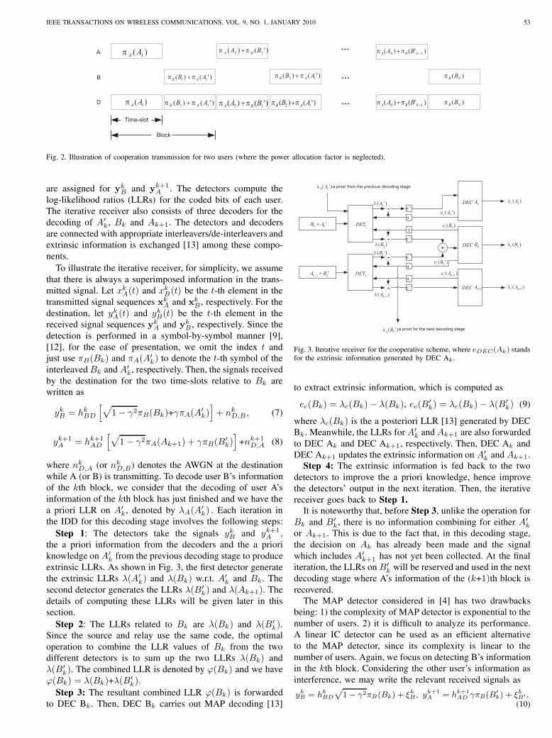
Fig. 2. Illustration of cooperation transmission for two users (where the power allocation factor is neglected).
are assigned for y𝑘𝐵 and y𝑘+1
𝐴 . The detectors compute thelog-likelihood ratios (LLRs) for the coded bits of each user.The iterative receiver also consists of three decoders for thedecoding of 𝐴′
𝑘 , 𝐵𝑘 and 𝐴𝑘+1. The detectors and decodersare connected with appropriate interleavers/de-interleavers andextrinsic information is exchanged [13] among these compo-nents.
To illustrate the iterative receiver, for simplicity, we assumethat there is always a superimposed information in the trans-mitted signal. Let 𝑥𝑘
𝐴(𝑡) and 𝑥𝑘𝐵(𝑡) be the 𝑡-th element in the
transmitted signal sequences x𝑘𝐴 and x𝑘
𝐵 , respectively. For thedestination, let 𝑦𝑘𝐴(𝑡) and 𝑦𝑘𝐵(𝑡) be the 𝑡-th element in thereceived signal sequences y𝑘
𝐴 and y𝑘𝐵 , respectively. Since the
detection is performed in a symbol-by-symbol manner [9],[12], for the ease of presentation, we omit the index 𝑡 andjust use 𝜋𝐵(𝐵𝑘) and 𝜋𝐴(𝐴
′𝑘) to denote the 𝑡-th symbol of the
interleaved 𝐵𝑘 and 𝐴′𝑘, respectively. Then, the signals received
by the destination for the two time-slots relative to 𝐵𝑘 arewritten as
𝑦𝑘𝐵 = ℎ𝑘𝐵𝐷
[√1− 𝛾2𝜋𝐵(𝐵𝑘)+𝛾𝜋𝐴(𝐴
′𝑘)]+ 𝑛𝑘
𝐷,𝐵, (7)
𝑦𝑘+1𝐴 = ℎ𝑘+1
𝐴𝐷
[√1− 𝛾2𝜋𝐴(𝐴𝑘+1) + 𝛾𝜋𝐵(𝐵
′𝑘)]+𝑛𝑘+1
𝐷,𝐴 (8)
where 𝑛𝑘𝐷,𝐴 (or 𝑛𝑘
𝐷,𝐵) denotes the AWGN at the destinationwhile A (or B) is transmitting. To decode user B’s informationof the 𝑘th block, we consider that the decoding of user A’sinformation of the 𝑘th block has just finished and we have thea priori LLR on 𝐴′
𝑘, denoted by 𝜆𝐴(𝐴′𝑘) . Each iteration in
the IDD for this decoding stage involves the following steps:Step 1: The detectors take the signals 𝑦𝑘𝐵 and 𝑦𝑘+1
𝐴 ,the a priori information from the decoders and the a prioriknowledge on 𝐴′
𝑘 from the previous decoding stage to produceextrinsic LLRs. As shown in Fig. 3, the first detector generatethe extrinsic LLRs 𝜆(𝐴′
𝑘) and 𝜆(𝐵𝑘) w.r.t. 𝐴′𝑘 and 𝐵𝑘. The
second detector generates the LLRs 𝜆(𝐵′𝑘) and 𝜆(𝐴𝑘+1). The
details of computing these LLRs will be given later in thissection.
Step 2: The LLRs related to 𝐵𝑘 are 𝜆(𝐵𝑘) and 𝜆(𝐵′𝑘).
Since the source and relay use the same code, the optimaloperation to combine the LLR values of 𝐵𝑘 from the twodifferent detectors is to sum up the two LLRs 𝜆(𝐵𝑘) and𝜆(𝐵′
𝑘). The combined LLR is denoted by 𝜑(𝐵𝑘) and we have𝜑(𝐵𝑘) = 𝜆(𝐵𝑘)+𝜆(𝐵′
𝑘).
Step 3: The resultant combined LLR 𝜑(𝐵𝑘) is forwardedto DEC B𝑘. Then, DEC B𝑘 carries out MAP decoding [13]
Fig. 3. Iterative receiver for the cooperative scheme, where 𝑒𝐷𝐸𝐶(𝐴𝑘) standsfor the extrinsic information generated by DEC A𝑘 .
to extract extrinsic information, which is computed as
𝑒𝑐(𝐵𝑘) = 𝜆𝑐(𝐵𝑘)− 𝜆(𝐵𝑘), 𝑒𝑐(𝐵′𝑘) = 𝜆𝑐(𝐵𝑘)− 𝜆(𝐵′
𝑘) (9)
where 𝜆𝑐(𝐵𝑘) is the a posteriori LLR [13] generated by DECB𝑘 . Meanwhile, the LLRs for 𝐴′
𝑘 and 𝐴𝑘+1 are also forwardedto DEC A𝑘 and DEC A𝑘+1, respectively. Then, DEC A𝑘 andDEC A𝑘+1 updates the extrinsic information on 𝐴′
𝑘 and 𝐴𝑘+1.Step 4: The extrinsic information is fed back to the two
detectors to improve the a priori knowledge, hence improvethe detectors’ output in the next iteration. Then, the iterativereceiver goes back to Step 1.
It is noteworthy that, before Step 3, unlike the operation for𝐵𝑘 and 𝐵′
𝑘, there is no information combining for either 𝐴′𝑘
or 𝐴𝑘+1. This is due to the fact that, in this decoding stage,the decision on 𝐴𝑘 has already been made and the signalwhich includes 𝐴′
𝑘+1 has not yet been collected. At the finaliteration, the LLRs on 𝐵′
𝑘 will be reserved and used in the nextdecoding stage where A’s information of the (𝑘+1)th block isrecovered.
The MAP detector considered in [4] has two drawbacksbeing: 1) the complexity of MAP detector is exponential to thenumber of users. 2) it is difficult to analyze its performance.A linear IC detector can be used as an efficient alternativeto the MAP detector, since its complexity is linear to thenumber of users. Again, we focus on detecting B’s informationin the 𝑘th block. Considering the other user’s information asinterference, we may write the relevant received signals as
𝑦𝑘𝐵 = ℎ𝑘
𝐵𝐷
√1− 𝛾2𝜋𝐵(𝐵𝑘) + 𝜉𝑘𝐵 , 𝑦𝑘+1
𝐴 = ℎ𝑘+1𝐴𝐷 𝛾𝜋𝐵(𝐵
′𝑘) + 𝜉𝑘𝐵′ ,
(10)

54 IEEE TRANSACTIONS ON WIRELESS COMMUNICATIONS, VOL. 9, NO. 1, JANUARY 2010
where𝜉𝑘𝐵 = ℎ𝑘
𝐵𝐷𝛾𝜋𝐴(𝐴′𝑘) + 𝑛𝑘
𝐷,𝐵
and𝜉𝑘𝐵′ = ℎ𝑘+1
𝐴𝐷
√1-𝛾2𝜋𝐴(𝐴𝑘+1) + 𝑛𝑘+1
𝐷,𝐴
are the interference plus noise for 𝐵𝑘 and 𝐵′𝑘. We use 𝐸
(𝜉𝑘𝐵)
and 𝐸(𝜉𝑘𝐵′)
to denote the estimated mean of the interferenceplus noise terms 𝜉𝑘𝐵 and 𝜉𝑘𝐵′ , respectively. The estimatedvariances of the interference plus noise terms are denoted by𝑉 𝑎𝑟(𝜉𝑘𝐵) and 𝑉 𝑎𝑟(𝜉𝑘𝐵′ ), respectively. Note that 𝐸(𝜉𝑘𝐵) and𝑉 𝑎𝑟(𝜉𝑘𝐵) are the estimated statistics, rather than the genuinestatistics. The genuine statistics are not known a priori. Theyare estimated from the decoders’ extrinsic outputs [9] and thedetails will be shown later, in Equations (13), (15) and (16).
By approximating 𝜉𝑘𝐵 and 𝜉𝑘𝐵′ as conditional Gaussianrandom variables, we can compute the extrinsic output ofthe IC detector for each coded bit independently. Again, weneglect the notations of interleavers in the sequel. For 𝐵𝑘, theoutput LLR from the IC detector is
𝜆(𝐵𝑘) = log𝑃 (𝐵𝑘 = 1∣𝑦𝑘
𝐵)
𝑃 (𝐵𝑘 = −1∣𝑦𝑘𝐵)
=2ℎ𝑘
𝐵𝐷
√1− 𝛾2
𝑉 𝑎𝑟(𝜉𝑘𝐵)
[𝑦𝑘𝐵 − 𝐸(𝜉𝑘𝐵)
].
(11)and we see that the estimated mean of the interference iscancelled from the received signal to compute the LLR. Themethod is referred to as interference cancellation [7], [14],[15]. Similarly, the LLR for 𝐵′
𝑘 is
𝜆(𝐵′𝑘) =
2ℎ𝑘+1𝐴𝐷 𝛾
𝑉 𝑎𝑟(𝜉𝑘𝐵′ )
[𝑦𝑘+1𝐴 − 𝐸(𝜉𝑘𝐵′ )
]. (12)
To find (11),(12), we need to find the mean and variance ofthe interference plus noise. These statistics are estimated fromthe decoder’s extrinsic output. In particular, the means of 𝜉𝑘𝐵and 𝜉𝑘𝐵′ are estimated as
𝐸(𝜉𝑘𝐵
)= ℎ𝑘
𝐵𝐷𝛾𝐸(𝐴′𝑘) ≈ ℎ𝑘
𝐵𝐷𝛾𝐸 [𝑒𝑐(𝐴𝑘′)] ,
𝐸(𝜉𝑘𝐵′)= ℎ𝑘+1
𝐴𝐷
√1-𝛾2𝐸(𝐴𝑘+1) ≈ ℎ𝑘+1
𝐴𝐷
√1-𝛾2𝐸 [𝑒𝑐(𝐴𝑘+1)]
(13)
where 𝑒𝑐(𝐴𝑘′ ) and 𝑒𝑐(𝐴𝑘+1) are the output extrinsic LLRsfrom the decoders DEC A𝑘 and DEC A𝑘+1. The approxima-tion in (13) is obtained because the mean of the interferingsignal 𝐸(𝐴′
𝑘) is estimated by 𝐸 [𝑒𝑐(𝐴𝑘′)]. Also, we have [9],[14]
𝐸 [𝑒𝑐(𝐴𝑘′ )] = tanh [𝑒𝑐(𝐴𝑘′ )/2] ,
𝐸 [𝑒𝑐(𝐴𝑘+1)] = tanh [𝑒𝑐(𝐴𝑘+1)/2] . (14)
The variances are computed as
𝑉 𝑎𝑟(𝜉𝑘𝐵)=∣∣ℎ𝑘
𝐵𝐷
∣∣2 𝛾2𝑉 𝑎𝑟(𝐴′𝑘) + 𝜎2 (15)
≈ ∣∣ℎ𝑘𝐵𝐷
∣∣2 𝛾2{1− [𝐸 (𝑒𝑐(𝐴𝑘′ ))]
2}+ 𝜎2
𝑉 𝑎𝑟(𝜉𝑘𝐵′)=∣∣ℎ𝑘+1
𝐴𝐷
∣∣2 (1 − 𝛾2)𝑉 𝑎𝑟(𝐴𝑘+1) + 𝜎2 (16)
≈ ∣∣ℎ𝑘+1𝐴𝐷
∣∣2 (1 − 𝛾2){1− [𝐸 (𝑒𝑐(𝐴𝑘+1))]
2}+ 𝜎2
where [9]
𝑉 𝑎𝑟(𝐴′𝑘) ≈ 1−[𝐸 (𝑒𝑐(𝐴𝑘′))]2 , 𝑉 𝑎𝑟(𝐴𝑘+1) ≈ 1−[𝐸 (𝑒𝑐(𝐴𝑘+1))]
2 .(17)
As the receiver iterates, the extrinsic LLRs from the de-coders are improved and the estimated statistics are updated,and this contributes to improved IC detector’s output.
IV. PERFORMANCE ANALYSIS AND POWER ALLOCATION
A. Strong Inter-user Channel
1) Conditional Pair-wise Error Probability (PEP): We firstconsider a case where each user can successfully decodeits partners information. This condition will be relaxed later.Generally, analyzing the performance of a scheme with IDDinvolves convergence analysis. Here, we just focus on derivingthe asymptotic conditional PEP of the scheme at high SNRs.Let 𝐴𝑘=𝐸 [𝑒𝑐(𝐴𝑘)] represent the decoder’s estimate on 𝐴𝑘 andsign(𝐴𝑘) represent the hard-decision of 𝐴𝑘 , where 𝐸 [𝑒𝑐(𝐴𝑘′ )]is given in (14). The variance of the residual interference afterthe soft cancellation is 𝐸(𝐴𝑘 −𝐴𝑘)
2 and that after the hard-decision cancellation is 𝐸(𝐴𝑘−sign(𝐴𝑘))
2. Before providingthe result on the asymptotic conditional PEP, we first presentan assumption.
Assumption 1: The variance of soft-cancellation is on thesame order of that of the hard-cancellation, i.e.,
𝐸(𝐴𝑘 −𝐴𝑘)2 = 𝐾 ⋅ 𝐸(𝐴𝑘 − sign(𝐴𝑘))
2, (18)
where 𝐾 is of a finite value.The physical meaning of the assumption is that, if
the variance of the hard-cancellation is finite, the vari-ance of the soft-cancellation is also finite, i.e. 𝐸(𝐴𝑘 −𝐴𝑘)
2/𝐸(𝐴𝑘−sign(𝐴𝑘))2 ∕= ∞. Here, the exact value of 𝐾
in (18) is not important. As long as K is finite, we can proveLemma 1, which will be given later. It is demonstrated thatAssumption 1 holds in the IDD for many applications [7], [9],[14]. As shown in [9], the difference between 𝐸(𝐴𝑘 − 𝐴𝑘)
2
and 𝐸(𝐴𝑘−sign(𝐴𝑘)) is tiny at a high SNR. Now, let uspresent a lemma for the conditional PEP of the schemefollowed by the proof.
Lemma 1: For sufficiently strong inter-user channel, asSNR−→ ∞ (or 𝜎2 −→ 0), the asymptotic PEP conditionedon ℎ𝑘
𝐵𝐷 and ℎ𝑘+1𝐴𝐷 for user B in the 𝑘th block approaches (19)
where 𝑄(𝑥) = 1√2𝜋
∫∞𝑥
exp(− 𝑡2
2
)𝑑𝑡 and 𝑑 is the Hamming
distance between two codewords.Proof: For the proposed scheme with IC detectors, the
signals with respect to 𝐵𝑘 are written as
𝑦𝑘𝐵 = ℎ𝑘𝐵𝐷
√1− 𝛾2𝜋𝐵(𝐵𝑘) + 𝜂1 + 𝑛𝑘
𝐷,𝐵, (20)
𝑦𝑘+1𝐴 = ℎ𝑘+1
𝐴𝐷 𝛾𝜋𝐵(𝐵′𝑘) + 𝜂2 + 𝑛𝑘+1
𝐷,𝐴, (21)
where 𝜂1=ℎ𝑘𝐵𝐷𝛾(𝐴′
𝑘-𝐴′𝑘) and 𝜂2=ℎ
𝑘+1𝐴𝐷
√1-𝛾2(𝐴𝑘+1-𝐴𝑘+1)
are the residual interference after IC, 𝐴′𝑘 and 𝐴𝑘+1 are
the decoder’s soft estimation on 𝐴′𝑘 and 𝐴𝑘+1. Since the
interference plus noise for 𝑦𝑘𝐵 and 𝑦𝑘+1𝐴 are not correlated,
these two signals can be combined with a MRC to form adecision statistic for user B. After the MRC, the SINR is given

IEEE TRANSACTIONS ON WIRELESS COMMUNICATIONS, VOL. 9, NO. 1, JANUARY 2010 55
𝑃𝑃𝐸𝑃ℎ𝑘𝐵𝐷 ,ℎ𝑘+1
𝐴𝐷
(𝛾2, 𝑑)→ 𝑄
⎛⎜⎜⎝√√√⎷2𝑑
[∣∣ℎ𝑘𝐵𝐷
∣∣2 +(∣∣ℎ𝑘+1
𝐴𝐷
∣∣2 − ∣∣ℎ𝑘𝐵𝐷
∣∣2) 𝛾2]
𝜎2
⎞⎟⎟⎠ (19)
by
𝜌𝑘𝐵(𝛾)=
[∣∣ℎ𝑘𝐵𝐷
∣∣2 (1− 𝛾2)]
∣∣ℎ𝑘𝐵𝐷
∣∣2 𝛾2𝐸(𝐴′𝑘 −𝐴′
𝑘)2 + 𝜎2
(22)
+
[∣∣ℎ𝑘+1𝐴𝐷
∣∣2 𝛾2]
∣∣ℎ𝑘+1𝐴𝐷
∣∣2 (1− 𝛾2)𝐸(𝐴𝑘+1 −𝐴𝑘+1)2 + 𝜎2
Now, let us investigate the relation between the vari-ance of the residual interference and the noise variancein (22). We will show that as SNR goes to infinity,
the variances of interferences∣∣ℎ𝑘
𝐵𝐷
∣∣ 𝛾2𝐸(𝐴′
𝑘 −𝐴′𝑘
)2and∣∣ℎ𝑘+1
𝐴𝐷
∣∣2 (1− 𝛾2)𝐸(𝐴𝑘+1 −𝐴𝑘+1
)2are negligible com-
pared to the noise variance 𝜎2. Given Assumption 1, thevariances of the residual interference in (22) become
𝐸(𝐴′𝑘-𝐴′
𝑘)2 = 𝐾 ⋅𝐸[𝐴′
𝑘-sign(𝐴′𝑘)]
2 = 4𝐾 ⋅ 𝑃𝑒(𝐴′𝑘), (23)
𝐸(𝐴𝑘+1-𝐴𝑘+1)2 = 𝐾 ⋅𝐸[𝐴𝑘+1-sign(𝐴𝑘+1)]
2=4𝐾 ⋅ 𝑃𝑒(𝐴𝑘+1)
where 𝑃𝑒(𝐴′𝑘) and 𝑃𝑒(𝐴𝑘+1) are the bit error probabilities
(BEPs) of the decoder’ hard-decision output. The instanta-neous SINR in (22) becomes
𝜌𝑘𝐵(𝛾2) =
[∣∣ℎ𝑘𝐵𝐷
∣∣2 (1− 𝛾2)]
4∣∣ℎ𝑘
𝐵𝐷
∣∣2 𝛾2𝐾 ⋅ 𝑃𝑒(𝐴′𝑘) + 𝜎2
(24)
+
[∣∣ℎ𝑘+1𝐴𝐷
∣∣2 𝛾2]
4∣∣ℎ𝑘+1
𝐴𝐷
∣∣2 (1− 𝛾2)𝐾 ⋅ 𝑃𝑒(𝐴𝑘+1) + 𝜎2.
Note that the channel coefficients, power allocation 𝛾2 and 𝐾are finite. As SNR→ ∞, we can show that
lim𝜎2→0
𝑃𝑒(𝐴′𝑘)
𝜎2= 0, lim
𝜎2→0
𝑃𝑒(𝐴𝑘+1)
𝜎2= 0. (25)
Given (25), as the SNR goes to infinity, the SINR in (24)becomes
𝜌𝑘𝐵(𝛾2)=
[∣∣ℎ𝑘𝐵𝐷
∣∣2 (1-𝛾2)]
4∣∣ℎ𝑘
𝐵𝐷
∣∣2 𝛾2𝐾𝑃𝑒(𝐴′𝑘) + 𝜎2
(26)
+
[∣∣ℎ𝑘+1𝐴𝐷
∣∣2 𝛾2]
4∣∣ℎ𝑘+1
𝐴𝐷
∣∣2 (1− 𝛾2)𝐾𝑃𝑒(𝐴𝑘+1) + 𝜎2
→[∣∣ℎ𝑘
𝐵𝐷
∣∣2 (1-𝛾2)]+[∣∣ℎ𝑘+1
𝐴𝐷
∣∣2 𝛾2]
𝜎2
for any finite values∣∣ℎ𝑘
𝐵𝐷
∣∣ , ∣∣ℎ𝑘+1𝐴𝐷
∣∣2 , 𝛾2 and 𝐾 . The proof of(25) is given in Appendix. Then, (19) is obtained.
From Lemma 1, we see that the conditional PEP at highSNRs is determined by the channel coefficients, the powerallocation factor and the noise variance, but not by theinterference. This shows that when the users can cooperate,the scheme asymptotically achieves the interference-free per-formance at high SNRs.
2) Average PEP and BEP: Now, let us find the averagePEP of the scheme. For Rayleigh fading channels where ℎ𝐵𝐷
and ℎ𝐴𝐷 follow 𝐶𝑁(0, 1), the PEP is given in the followingtheorem.
Theorem 1: As the SNR−→ ∞, the PEP of the proposedscheme with an IC detectors approaches
𝑃𝑃𝐸𝑃 (𝛾2, 𝑑) −→[
3
16𝑑2(1− 𝛾2)𝛾2
]𝑆𝑁𝑅−2 (27)
provided that the inter-user channel is sufficiently strong thatthe users can cooperate.
Proof: The SINR 𝜌𝑘𝐵(𝛾2) in (26) follows a generalized
Chi-square distribution whose PDF is
𝑝[𝜌𝑘𝐵(𝛾
2) = 𝑎]=
∂𝑃{𝜌𝑘𝐵(𝛾) < 𝑎
}∂𝑎
(28)
=1
2𝛾2 − 1
[exp(− 𝑎
𝛾2)− exp(− 𝑎
1− 𝛾2)
].
By averaging the conditional PEP in (19) over the PDF ofthe SINR, the PEP is given by
𝑃𝑃𝐸𝑃 (𝛾2, 𝑑) →1
2
𝛾2
2𝛾2-1
[1-
√1
1+ 1𝑆𝑁𝑅⋅𝑑⋅𝛾2
]
− 1
2
1-𝛾2
2𝛾2-1
[1-
√1
1+ 1𝑆𝑁𝑅⋅𝑑⋅(1−𝛾2)
](29)
Using the fact that√1
1 + 𝑥= 1− 1
2𝑥+
3
8𝑥2+𝑂(
1
𝑥2), (30)
at high SNRs, we obtain (27) and that completes the proof.
From Theorem 1, we see that when the inter-user channelis sufficiently strong, the scheme achieves a diversity order oftwo. The optimal power allocation that minimizes the PEP isgiven in the following corollary.
Corollary 1: As the SNR−→ ∞, if the two users cancooperate, the minimum PEP of the scheme is achieved withan equal power allocation, that is 𝛾2 =1− 𝛾2 = 1
2 .Proof: At high SNRs, we have
𝑃𝑃𝐸𝑃 (𝛾2, 𝑑) −→[
3
16𝑑2(1− 𝛾2)𝛾2
]𝑆𝑁𝑅−2 ≥ 3
4𝑑2𝑆𝑁𝑅−2,
(31)where we use the fact that√
(1 − 𝛾2)𝛾 ≤ (1− 𝛾2) + 𝛾2
2=
1
2. (32)
The smallest value of the 𝑃𝑃𝐸𝑃 (𝛾2, 𝑑) is achieved when 𝛾2 =1− 𝛾2 = 1/2 and Corollary. 1 is proved.
The result in Corollary 1 is different from that given in [4]which shows by simulation that the best power allocation isabout 𝛾2=0.15, where iterative receiver is not employed.

56 IEEE TRANSACTIONS ON WIRELESS COMMUNICATIONS, VOL. 9, NO. 1, JANUARY 2010
For block fading channels, we now derive a partial limit-before-averaging (LBA) bound [16], [17] to the BEP, whichcan be readily shown as
𝑃 𝑏𝑖𝑡(𝛾2) ≈∫ ∞
0
min
[4∑
𝑖=0
𝑒(𝑑𝑓𝑟𝑒𝑒+𝑖)𝑄
(√2𝑑𝑓𝑟𝑒𝑒+𝑖𝜌𝑘𝐵(𝛾
2)
),1
2
]⋅ 𝑝[𝜌𝑘𝐵(𝛾
2)]𝑑𝜌𝑘𝐵(𝛾
2) (33)
where the SINR 𝜌𝑘𝐵(𝛾) is given in (26). Moreover,𝑒(𝑑), 𝑑=𝑑𝑓𝑟𝑒𝑒,..., 𝑑max, is the error-weighted distance spec-trum, 𝑑𝑓𝑟𝑒𝑒 is the free-distance of the channel code and 𝑑max
is the maximum Hamming distance considered in evaluatingthe error-weighted distance spectrum. For example, in thispaper, we consider a system with a half-rate convolutionalcode and generator polynomials [23, 35]8. The free distanceis 𝑑𝑓𝑟𝑒𝑒 = 7 and the error-weighted distance spectrum can befound in [19].
B. General Cases
Now, we generalize the analysis to cases of arbitrary inter-user channel quality. If the instantaneous inter-user channel∣∣ℎ𝑘
𝐴𝐵
∣∣2 𝑆𝑁𝑅 is weak, a user may not be able to decodeits partner’s information and the cooperative scheme boilsdown to a direct transmission. Given an inter-user channelcoefficient ℎ𝐴𝐵 , the probability of unsuccessful decoding isrelated to the bit error probability (BEP) of the inter-userdecoding. Considering a block fading channel scenario with𝐿 information bits per block, the LBA bound on the BEP isgiven in (34) (see next page) where (35) (see next page).
Note that the term{1-[1-𝑃 𝑏𝑖𝑡
ℎ𝐴𝐵(𝛾2)]𝐿}
in (34) is theconditional frame error probability (FEP) of the inter-userchannel given ℎ𝐴𝐵 and a frame length of 𝐿.
Given (34), the optimal power allocation factor is given by
𝛾2𝑜𝑝𝑡 = argmin
𝛾2𝑃 𝑏𝑖𝑡(𝛾2). (36)
Unfortunately, there is no close-form solution to (36) since theBEP given in (35) is non-linear. For general cases, 𝛾2
𝑜𝑝𝑡 canonly be found numerically. However, at high SNR, we havethe following Theorem:
Theorem 2: For general cases, the PEP of the proposedcooperative scheme approaches
𝑃𝑃𝐸𝑃 (𝛾2, 𝑑) →[
3
16𝑑2(1− 𝛾2)𝛾2
]𝑆𝑁𝑅−2. (37)
Proof: As SNR approaches infinity, we obtain (38)Moreover, we can find
[1-𝑃 𝑏𝑖𝑡
ℎ𝐴𝐵(𝛾2)]𝐿 𝑆𝑁𝑅→∞−→ 1, 1-[
1-𝑃 𝑏𝑖𝑡ℎ𝐴𝐵
(𝛾2)]𝐿 𝑆𝑁𝑅→∞−→ 𝐿 ⋅ 𝑃 𝑏𝑖𝑡
ℎ𝐴𝐵(𝛾2) for a finite 𝐿. As a
result, for a very high SNR, we have (39) where the last stepderivation is due to the fact that
lim𝑆𝑁𝑅→∞
𝐿𝑃 𝑏𝑖𝑡ℎ𝐴𝐵
(𝛾2)
𝑆𝑁𝑅−1= 0
for any finite 𝐿, since 𝑃 𝑏𝑖𝑡ℎ𝐴𝐵
(𝛾2) decreases exponentially with𝑆𝑁𝑅. Theorem 2 has now been proved.
10 12 14 16 18 20 22 24 26 28 3010
−5
10−4
10−3
10−2
SNR(dB)
BE
R
Larrson & VojcicIterative receiver with MAP detectorsIterative receiver with IC detectorsPredicted performance
Fig. 4. Performance of the iterative receivers with a convolutional code,SNR𝐴𝐵=SNR.
10 12 14 16 18 20 22 24 26 28 3010
−5
10−4
10−3
10−2
SNR(dB)
BE
R
Larrson & Vojcic scheme with Convolutional codeProposed scheme with Convolutional codeGene−aided with Convolutional codeLarrson & Vojcic scheme with Turbo codeProposed scheme with a Turbo codeGene−aided with a Turbo code
Fig. 5. Performance of the iterative receivers with a convolutional code anda turbo code, SNR𝐴𝐵=SNR.
V. SIMULATIONS
In this section, we show the performance of the proposedschemes. The simulation environment is depicted as follows:The channel coefficients follow Rayleigh distribution and theyremain constant for at least one block. The average SNRsof user-to-destination channels are the same, i.e. SNR𝐴𝐷 =SNR𝐵𝐷, and they are equal to the benchmark SNR. The SNRof the inter-user channel SNR𝐴𝐵 is not necessarily the same asSNR and we are interested in the cases that SNR𝐴𝐵≥SNR, i.e.SNR𝐴𝐵(dB)=SNR(dB) or SNR𝐴𝐵(dB)=SNR(dB)+20dB.Weadopt baseband BPSK modulation and employ a rate 1/2 non-systematic convolutional code and turbo code, where there are256 information bits for each time-slot. In each IDD operation,five iterations are performed.
First of all, we consider a system with equal power alloca-tion. The scheme in [4] serves as the benchmark system, where15% of transmission energy is allocated to the superimposed

IEEE TRANSACTIONS ON WIRELESS COMMUNICATIONS, VOL. 9, NO. 1, JANUARY 2010 57
𝑃 𝑏𝑖𝑡(𝛾2) ≈∫ ∞
0
{[1-𝑃 𝑏𝑖𝑡
ℎ𝐴𝐵(𝛾2)
]𝐿 ∫ ∞
0
min
[4∑
𝑖=0
𝑒(𝑑𝑓𝑟𝑒𝑒+𝑖)𝑄
(√2𝑑𝑓𝑟𝑒𝑒+𝑖𝜌𝑘𝐵(𝛾
2)
),1
2
]𝑝[𝜌𝑘𝐵(𝛾
2)]𝑑𝜌𝑘𝐵(𝛾
2) (34)
+
(1-[1-𝑃 𝑏𝑖𝑡
ℎ𝐴𝐵(𝛾2)
]𝐿)∫ ∞
0
min
⎡⎣ 4∑𝑖=0
𝑒(𝑑𝑓𝑟𝑒𝑒+𝑖)𝑄
⎛⎝√2𝑑𝑓𝑟𝑒𝑒+𝑖 ∣ℎ𝐵𝐷∣2𝜎2
⎞⎠ ,1
2
⎤⎦(𝑝 ∣ℎ𝐵𝐷∣2) 𝑑 ∣ℎ𝐵𝐷∣2⎫⎬⎭ 𝑝
(∣ℎ𝐴𝐵 ∣2) 𝑑 ∣ℎ𝐴𝐵 ∣2
𝑃 𝑏𝑖𝑡ℎ𝐴𝐵
(𝛾2) ≈ min
[4∑
𝑖=0
𝑒(𝑑𝑓𝑟𝑒𝑒+𝑖)𝑄
(√2𝑑𝑓𝑟𝑒𝑒+𝑖 ∣ℎ𝐴𝐵∣2 (1-𝛾2)
),1
2
]. (35)
𝑃 𝑏𝑖𝑡ℎ𝐴𝐵
(𝛾2)=min
⎡⎣ 4∑𝑖=0
𝑒(𝑑𝑓𝑟𝑒𝑒+𝑖)𝑄
⎛⎝√2𝑑𝑓𝑟𝑒𝑒+𝑖 ∣ℎ𝐴𝐵∣2 (1-𝛾2)
𝜎2
⎞⎠ ,1
2
⎤⎦≈
4∑𝑖=0
𝑒(𝑑𝑓𝑟𝑒𝑒+𝑖)𝑄
⎛⎝√2𝑑𝑓𝑟𝑒𝑒+𝑖 ∣ℎ𝐴𝐵∣2 (1-𝛾2)
𝜎2
⎞⎠ . (38)
𝑃𝑃𝐸𝑃 (𝛾2, 𝑑)
→∫ ∞
0
[3𝑆𝑁𝑅−2
16𝑑2(1-𝛾2)𝛾2+3𝐿𝑃 𝑏𝑖𝑡
ℎ𝐴𝐵(𝛾2)𝑆𝑁𝑅−1
4𝑑
]𝑝(∣ℎ𝐴𝐵∣2
)𝑑 ∣ℎ𝐴𝐵∣2
→[
3
16𝑑2(1− 𝛾2)𝛾2
]𝑆𝑁𝑅−2 (39)
10 12 14 16 18 20 22 24 26 28 3010
−5
10−4
10−3
10−2
SNR(dB)
BE
R
Larrson & VojcicIterative receiver with MAP detectors without interleavingIterative receiver with MAP detectorsIterative receiver with IC detectorsPredicted performance
Fig. 6. Performance of the iterative receivers with a convolutional code, 𝛾2 =0.5, SNR𝐴𝐵 (dB)=SNR(dB)+20dB.
signal1. Fig. 4 shows the BERs of the schemes versus theaverage SNR, where SNR𝐴𝐵(dB)=SNR(dB). In this figure,the BERs of the scheme in [4], our proposed scheme withMAP detectors and that with the IC detectors are plotted wherea convolutional code with generator polynomials [23, 35]8 isused. The predicted performance given in (34) is also included.
1It was found via simulations that 𝛾2 = 0.15 almost results in the smallesterror rate for the scheme in [4] without IDD.
0.1 0.2 0.3 0.4 0.5 0.6 0.7 0.8 0.910
−6
10−5
10−4
10−3
10−2
10−1
Power allocated to the superimposed information
Bit
erro
r pr
obab
ility
10 dB
15 dB
20 dB
25 dB
Fig. 7. Predicted BERs with various power allocation factors (convolutionalcode), SNR𝐴𝐵 (dB)=SNR(dB)+20dB.
At a BER of 10−5, we observe that the proposed schemeperforms about 2 dB better than the scheme in [4] and theproposed scheme with IC detectors achieves the performanceof that with the MAP detectors. Moreover, the performanceof the iterative receiver is very close to the analytical resultgiven in (34). In Fig. 5, we compare the performance ofthe schemes with both a convolutional code and a turbocode whose generator polynomials are [1/37, 1/21]8. We alsoplotted the interference-free (gene-aided) performance. It is

58 IEEE TRANSACTIONS ON WIRELESS COMMUNICATIONS, VOL. 9, NO. 1, JANUARY 2010
10 15 20 2510
−5
10−4
10−3
10−2
SNR(dB)
BE
Rγ=sqrt(0.1)γ=sqrt(0.3)γ=sqrt(0.5)
Fig. 8. Performance of the iterative receivers (convolutional code) withdifferent values of 𝛾2, SNR𝐴𝐵 (dB)=SNR(dB)+20dB.
observed that, when a strong channel code is used, the pro-posed scheme still achieves the interference-free performanceand the performance improvement of the turbo code relativeto a convolutional code is about 1-1.5 dB at BER of 10−4.
Now, we consider a scenario that the inter-user channel isstronger than the user-destination channels, i.e., the distancebetween the two users are shorter than that between a user andthe destination. In the simulations for Fig. 6, we consider thatSNR𝐴𝐵(dB)=SNR(dB)+20dB. At a BER of 10−5, we observethat the performance improvement by using the proposedscheme relative to [4] is about 3.5 dB. We see that as theinter-user channel becomes stronger, a larger improvementis obtained by using the proposed scheme relative to thebench mark scheme. Moreover, for all SNR cases, the BERperformance of the schemes is very tight to the analyticalresult given in (34). At high SNRs, the BER is proportional to𝑆𝑁𝑅−2. In Fig. 6, we also plot the BERs of our scheme wherethe interleavers are not used, as denoted by the dotted curves.The gap between the schemes with and without interleaver isnot minor, and it becomes larger when the inter-user channelquality improves.
Now, we evaluate the performance of thescheme with different power allocation factors whereSNR𝐴𝐵(𝑑𝐵) =SNR(𝑑𝐵) + 20dB. The predicted errorprobabilities versus different power allocation factors 𝛾2,which is computed from (34), are plotted in Fig. 7. Eachcurve in the figure shows the predicted BER of the schemewith a variety of 𝛾2 and a fixed SNR. For a wide rangeof SNRs, we see that the best power allocation factor is𝛾2=0.5. This lines up with the result given in Theorem 2.However, it is strikingly different from that given in [4],where the authors mentioned that the best power allocationfactor is about 𝛾2=0.15 when IDD is not employed. In Fig.8, we plot the simulated BERs of the proposed scheme with𝛾2 = 0.1, 𝛾2 = 0.3 and 𝛾2 = 0.5. We observe that thescheme with 𝛾2 = 0.5 achieves the best performance. Thisresult is consistent with the analytical result given in SectionIV and Fig. 7.
Finally, let us compare the complexity of the proposed
scheme to that of [4]. Since we need to perform the detectionfor 𝐼 times and the decoding for 𝐼 times for each block,where 𝐼 is the total number of iterations, the complexity ofour scheme is exactly 𝐼 times the complexity of that in [4].Moreover, the processing delay for the proposed scheme, i.e.the number of blocks to be collected before the IDD starts, isthat same as that in [4].
VI. CONCLUSIONS
In this paper, we proposed a new transceiver for thecooperative scheme based on superposition modulation. Weinvestigated a receiver with IDD for the proposed cooperativetransmission strategy. For quasi-static fading environment, weanalyzed the BER performance of the receiver for the proposedscheme and derived the optimal power allocation for thesuperposition modulation. Simulation shows that the proposedscheme is about 2-3.5 dB better than the scheme in [4], andthe simulated BER is very close to the predicted BER for awide range of SNRs.
APPENDIX
Proof: [Proof of (25)] Let 𝑒(𝑑), 𝑑=𝑑𝑓𝑟𝑒𝑒,..., 𝑑max, denotethe error-weighted distance spectrum of the channel code [18],[19], where 𝑑𝑓𝑟𝑒𝑒 is the free-distance of the channel codeand 𝑑max is the maximum Hamming distance considered inevaluating the error-weighted distance spectrum. Let us beginwith 𝑘=1, and consider that user A transmits first. At highSNRs, the conditional bit error probability of 𝐴1 is upper-bounded by [18], [19]
𝑃𝑒(𝐴1) ≤𝑑max∑
𝑑=𝑑𝑓𝑟𝑒𝑒
𝑒(𝑑)𝑄
⎛⎝√2𝑑 ∣ℎ1𝐴𝐷∣2
𝜎2
⎞⎠ (40)
Here, the inequality holds for two reasons: 1) The right handside of the inequality is obtained by using a union bound. 2)The right hand side is computed by considering only a singletime-slot. In the cooperative scheme with IDD, the informationof 𝐴1 resides in two adjacent time-slots. By jointly consideringthese two time-slots, the BEP w.r.t 𝐴1 is not greater than thatobtained by considering only a single time-slot.
For any non-zero∣∣ℎ1
𝐴𝐷
∣∣2, since 𝑄(
√2𝑑 ∣ℎ1
𝐴𝐷∣2 /𝜎2)
decays exponentially with 1𝜎2 , we have
lim𝜎2→0
𝑄(
√2𝑑 ∣ℎ1
𝐴𝐷∣2 /𝜎2)/𝜎2=0 so that
lim𝜎2→0
𝑃𝑒(𝐴1)
𝜎2= 0. (41)
Here, (41) suggests that as 𝜎2 → 0, we have
𝐷 ⋅ 𝑃𝑒(𝐴1)𝜎2→0≤ 𝜎2 (42)
where 𝐷 is any finite constant and “𝑥 ≤𝜎2→0
𝑦 denote that as
𝜎2 → 0, 𝑥 ≤ 𝑦. Given the error probability of 𝐴1, we have

IEEE TRANSACTIONS ON WIRELESS COMMUNICATIONS, VOL. 9, NO. 1, JANUARY 2010 59
𝑃𝑒(𝐵1) ≤𝑑max∑
𝑑=𝑑𝑓𝑟𝑒𝑒
𝑒(𝑑)𝑄
⎛⎝√√√⎷ 2(1-𝛾2)𝑑 ∣ℎ1
𝐵𝐷∣2𝜎2+𝛾2 ∣ℎ1
𝐵𝐷∣2 𝐸(𝐴′1 −𝐴′
1)2
⎞⎠=
𝑑max∑𝑑=𝑑𝑓𝑟𝑒𝑒
𝑒(𝑑)𝑄
⎛⎝√√√⎷ 2(1-𝛾2)𝑑 ∣ℎ1
𝐵𝐷∣2𝜎2+4𝐾𝛾2 ∣ℎ1
𝐵𝐷∣2 𝑃𝑒(𝐴′1)
⎞⎠(43)
=
𝑑max∑𝑑=𝑑𝑓𝑟𝑒𝑒
𝑒(𝑑)𝑄
⎛⎝√√√⎷ 2(1-𝛾2)𝑑 ∣ℎ1
𝐵𝐷∣2𝜎2+4𝐾𝛾2 ∣ℎ1
𝐵𝐷∣2 𝑃𝑒(𝐴1)
⎞⎠(44)
where the equality of (43) is due to (23). The equalityin (44) is because of that 𝐴1 and 𝐴′
1 are subjected to thesame codebook so that their BEPs are the same, that is𝑃𝑒(𝐴1)=𝑃𝑒(𝐴
′1). Note that 𝛾2,𝐾,
∣∣ℎ1𝐵𝐷
∣∣2 are finite. Then,considering (42), we have
𝑃𝑒(𝐵1)𝜎2→0≤
𝑑max∑𝑑=𝑑𝑓𝑟𝑒𝑒
𝑒(𝑑)𝑄
⎛⎝√2(1− 𝛾2)𝑑 ∣ℎ1𝐵𝐷∣2
𝜎2 + 𝜎2
⎞⎠ . (45)
Similar to the case of 𝐴1 in (41) and (42), we obtainlim𝜎2→0
𝑃𝑒(𝐵1)/𝜎2=0 and
𝐷 ⋅ 𝑃𝑒(𝐵1) ≤𝜎2→0
𝜎2. (46)
Given the error probability of 𝐵1, the asymptotic bit errorprobability of 𝐴2 is
𝑃𝑒(𝐴2) ≤𝑑max∑
𝑑=𝑑𝑓𝑟𝑒𝑒
𝑒(𝑑)𝑄
⎛⎝√√√⎷ 2(1− 𝛾2)𝑑 ∣ℎ2
𝐴𝐷∣2𝜎2 + 4𝐾 ⋅ 𝛾2 ∣ℎ2
𝐴𝐷∣2 𝑃𝑒(𝐵1)
⎞⎠𝜎2→0≤
𝑑max∑𝑑=𝑑𝑓𝑟𝑒𝑒
𝑒(𝑑)𝑒𝑟𝑓𝑐
⎛⎝√2(1− 𝛾2)𝑑 ∣ℎ2𝐴𝐷∣2
𝜎2 + 𝜎2
⎞⎠(47)
and that of 𝐴′1 is
𝑃𝑒(𝐴′1) ≤
𝑑max∑𝑑=𝑑𝑓𝑟𝑒𝑒
𝑒(𝑑)𝑄
(√2𝛾2𝑑 ∣ℎ1
𝐴𝐷∣2𝜎2 + 4𝐾 ⋅ (1− 𝛾2) ∣ℎ1
𝐴𝐷∣2 𝑃𝑒(𝐵1)
)
𝜎2→0≤𝑑max∑
𝑑=𝑑𝑓𝑟𝑒𝑒
𝑒(𝑑)𝑒𝑟𝑓𝑐
⎛⎝√2𝛾2𝑑 ∣ℎ1𝐴𝐷∣2
𝜎2 + 𝜎2
⎞⎠ (48)
where the inequalities hold since we have (46). Then, weobtain
lim𝜎2→0
𝑃𝑒(𝐴2)
𝜎2= 0, lim
𝜎2→0
𝑃𝑒(𝐴′1)
𝜎2= 0 (49)
Using the same method as in the above, for the 𝑘th block,itis straightforward to find (25).
REFERENCES
[1] T. M. Cover and E. Gamal, “Capacity theorems for the relay channel,"IEEE Trans. Inf. Theory, vol. 25, pp. 572-584, Sept. 1979.
[2] J. N. Laneman, D. N. C. Tse, and G. W. Wornell, “Cooperative diversityin wireless networks: efficient protocols and outage behavior," IEEETrans. Inf. Theory, vol. 50, no. 12, pp. 3062-3080, Dec. 2004.
[3] K. Azarian, H. E. Gamal, and P. Schniter, “On the achievable diversity-multiplexing tradeoff in half-duplex cooperative channels," IEEE Trans.Inf. Theory, vol. 51, no. 12, pp. 4152-4172, Dec. 2005.
[4] E. G. Larsson and B. R. Vojcic, “Cooperative transmit diversity basedon superposition modulation," IEEE Commun. Lett., vol. 9, no. 9, Sept.2005.
[5] Z. Ding, T. Ratnarajah, and C. Cowan, “Cooperative multiple accesssystems using superposition modulation," in Proc. IEEE Inf. TheoryWorkshop (ITW 2006), Oct. 2006.
[6] Z. Ding, T. Ratnarajah, and C. Cowan, “On the diversity-multiplexingtradeoff for wireless cooperative multiple access systems," IEEE Trans.Signal Process., vol. 55, no. 9, Sept. 2007.
[7] T. Yang, J. Yuan, Z. Shi, and M. C. Reed, “Convergence behavioranalysis and detection switching for iterative receiver of MIMO-BICMsystems," IEEE Trans. Veh. Technol., vol. 57, no. 4, pp. 2642-2648, July2008.
[8] B. M. Hochwald and S. ten Brink, “Achieving near-capacity on amultiple-antenna channel," IEEE Trans. Commun., vol. 51, no. 3, pp.389-400, Mar. 2003.
[9] P. Li, L. Liu, K. Y. Wu, and W. K. Leung, “Interleave-division multiple-access," IEEE Trans. Wireless Commun., vol. 4, pp. 938-947, Apr. 2006.
[10] X. Ma and P. Li, “Power allocations for multilevel coding with sigmamapping," Electron. Lett., vol. 40, no. 10, pp. 609-611, May 2004.
[11] Y. Ueng, C. Yeh, M. Lin, and C. Wang, “Turbo coded multiple-antennasystems for near-capacity performance," IEEE J. Sel. Areas Commun.,vol. 27, no. 6, pp. 954-964, Aug. 2009.
[12] T. Yang, J. Yuan, and Z. Shi, “Jointly Gaussian approximation andmulti-stage LLR combining in the iterative receiver for MIMO-BICMsystems," IEEE Trans. Wireless Commun., vol. 7, no. 12, pp. 5250-5256,Dec. 2008.
[13] C. Berrou, A. Glavieux, and P. Thitimajshima, “Near Shannon limiterror-correcting coding and decoding: turbo-codes," in Proc. ICC 93,Geneva, Switzerland, pp. 1064-1070, May 1993.
[14] Z. Shi and C. Schlegel, “Iterative multisuser detection and error controlcode decoding in random CDMA," IEEE Trans. Signal Process., vol.54, no. 5, pp. 1886-1895, May 2006.
[15] L. Trichard, J. Evans, and I. Collings, “Large system analysis of linearmultistage parallel interference cancellation," IEEE Trans. Commun.,vol. 50, no. 11, pp. 1778-1786, Nov. 2002.
[16] T. Yang and J. Yuan, “Performance of MIMO-BICM with parallelinterference canceller on slow fading channels," IEE Electron. Lett.,pp. 1292-1293, vol. 42, no. 22, Oct. 2006.
[17] E. Malkamaki and H. Leib, “Evaluating the performance of convolu-tional codes over block fading channels," IEEE Trans. Inf. Theory, vol.45, no. 2, pp. 1643-1646, July 1999.
[18] J. Proakis, Digital Communicaitons, 2nd ed. McGraw Hill, 2001.[19] A. Burr, Modulation and Coding for Wireless Communications. Prentice
Hall, 2003.[20] Z. Zhang and T. M. Duman, “Capacity-approaching turbo coding and
iterative decoding for relay channels," IEEE Trans. Commun., vol. 53,no. 11, Nov. 2005.