Embed Size (px)
Citation preview

___________________________________________________________________________________________________________________________________________________
1 PhD Candidate, Dept. of Civil and Environmental Engineering, The University of Auckland, Auckland, New Zealand
2 Assoc. Professor, Dept. of Civil and Environmental Engineering, The University of Auckland, Auckland, New Zealand
3 PhD Candidate, School of Civil, Environmental and Mining Engineering, The University of Adelaide, Adelaide, Australia
4 Professor, School of Civil, Environmental and Mining Engineering, The University of Adelaide, Adelaide, Australia
5 Professor, Dept. of Civil Engineering, The University of Minnesota, Minneapolis, United States of America
6 PhD Candidate, Centre for Post-graduate Training and Research in Earthquake Engineering & Engineering Seismology (ROSE
School), Pavia, Italy
7 Assoc. Professor, Dept. of Structural Mechanics, The University of Pavia, Italy
8 PhD Candidate, Dept. of Civil Engineering, The University of Calgary, Canada
9 Assoc. Professor, Dept. of Civil Engineering, The University of Calgary, Canada
10 PhD Candidate, Dept. of Civil Engineering, The University of British Columbia, Vancouver, Canada
11 Professor, Dept. of Civil Engineering, The University of British Columbia, Vancouver, Canada
12 PhD Candidate, Dept. of Civil Engineering, The University of Minho, Guimarães, Portugal
13 Professor, Dept. of Civil Engineering, The University of Minho, Guimarães, Portugal
279
PERFORMANCE OF MASONRY BUILDINGS AND
CHURCHES IN THE 22 FEBRUARY 2011 CHRISTCHURCH
EARTHQUAKE
Dmytro Dizhur1, Jason Ingham
2, Lisa Moon
3, Mike Griffith
4,
Arturo Schultz5, Ilaria Senaldi
6, Guido Magenes
7,
Jocelyn Dickie8, Shelley Lissel
9, Jose Centeno
10,
Carlos Ventura11
, Joao Leite12
and Paulo Lourenco13
SUMMARY
As part of the „Project Masonry‟ Recovery Project funded by the New Zealand Natural Hazards Research
Platform, commencing in March 2011, an international team of researchers was deployed to document and
interpret the observed earthquake damage to masonry buildings and to churches as a result of the 22nd
February 2011 Christchurch earthquake. The study focused on investigating commonly encountered failure
patterns and collapse mechanisms. A brief summary of activities undertaken is presented, detailing the
observations that were made on the performance of and the deficiencies that contributed to the damage to
approximately 650 inspected unreinforced clay brick masonry (URM) buildings, to 90 unreinforced stone
masonry buildings, to 342 reinforced concrete masonry (RCM) buildings, to 112 churches in the Canterbury
region, and to just under 1100 residential dwellings having external masonry veneer cladding. In addition,
details are provided of retrofit techniques that were implemented within relevant Christchurch URM
buildings prior to the 22nd February earthquake and brief suggestions are provided regarding appropriate
seismic retrofit and remediation techniques for stone masonry buildings.
INTRODUCTION
In the early morning of 4th September 2010 the region of
Canterbury, New Zealand, was subjected to a magnitude M7.1
earthquake. The epicentre was located near the town of
Darfield, 40 km west of the city of Christchurch. This was the
country‟s most damaging earthquake since the 1931 Hawke‟s
Bay earthquake [1]. Since 4th September 2010 the region has
been subjected to thousands of aftershocks, including several
more damaging events such as a magnitude M6.3 aftershock
on 22nd February 2011. Although of a smaller magnitude, the
earthquake on 22nd February produced peak ground
BULLETIN OF THE NEW ZEALAND SOCIETY FOR EARTHQUAKE ENGINEERING, Vol. 44, No. 4, December 2011

280
accelerations in the Christchurch region that were substantially
greater than those measured during the 4th September
earthquake and in some locations generated shaking intensities
greater than twice the design level [2, 3]. Whilst in September
2010 most earthquake shaking damage was limited to
unreinforced masonry (URM) buildings, in February 2011 all
types of buildings sustained damage. Temporary shoring and
strengthening techniques applied to buildings following the
Darfield earthquake were tested in February 2011. In
addition, two large aftershocks (magnitudes M5.7 and M6.2)
occurred on 13th June 2011, further damaging many already
weakened structures.
Commencing in March 2011 an international team of
researchers was deployed to document and interpret the
observed earthquake damage to masonry buildings and to
churches, by investigating the failure patterns and collapse
mechanisms that were commonly encountered. This initiative
was undertaken as part of the „Project Masonry‟ Recovery
Project funded by the New Zealand Natural Hazards Research
Platform.
A brief summary of activities undertaken as part of Project
Masonry is presented, detailing the observations that were
made on the performance and the deficiencies that contributed
to the observed damage of:
Unreinforced clay brick masonry (URM) buildings, and
earthquake strengthening (or seismic retrofitting)
techniques that were implemented within relevant
Christchurch URM buildings prior to the 22nd February
earthquake;
Unreinforced stone masonry buildings (including brief
suggestions on appropriate seismic retrofit and
remediation techniques);
Reinforced concrete masonry (RCM) buildings, including
specific case study RCM buildings;
Churches in the Canterbury region;
Residential dwellings having external masonry veneer
cladding.
UNREINFORCED CLAY BRICK MASONRY
BUILDINGS
Unreinforced masonry buildings are known to behave poorly
in large earthquakes. In New Zealand the majority of the
existing URM building stock was constructed before the 1931
Hawke‟s Bay earthquake, and represents a significant
proportion of New Zealand‟s architectural historic [4]. Over
650 unreinforced clay brick masonry buildings were inspected
in the Christchurch area from March 2011 onwards, with the
distribution of the inspected URM buildings illustrated in
Figure 1. While some of the buildings that were more
severely damaged in September 2010 had been demolished
prior to February 2011, many more had received temporary
shoring and strengthening, and a number of these buildings
were barricaded and hence unoccupied at the time of the 22nd
February 2011 earthquake. The damage to unreinforced and
retrofitted clay brick masonry buildings in the 4th September
2010 Darfield earthquake was reported previously by Dizhur
et al. [5] and by Ingham and Griffith [6].
Figure 1: Location of inspected URM buildings.
Building demolition statistics
In the period between 22nd February and 25th July 2011 almost
200 URM buildings were demolished [7]. These 200 URM
buildings account for approximately 85% of all buildings
demolished during this time. Of those URM buildings that
remain, few are currently in an occupiable condition. An
example of the extensive demolition of URM buildings that
took place following the 13th June aftershock is presented in
Figure 2.
Figure 2: Extensive building demolition following the 13th
June 2011 aftershock.
Material properties
Brick and mortar samples were collected from Christchurch
URM buildings following the 4th September 2010 and 22nd
February 2011 earthquakes. The mortar was typically lime
based mortar, which due to low compressive strength could be
crumbled by finger pressure. The average normalised
compressive strength of the 293 mortar samples collected
from 61 URM building sites in Christchurch was found to be
2.6 MPa, with a strength range from 0.45 MPa to 25.3 MPa. It
is expected that the highest readings were for samples
containing modern cement mortar used in repointing
(remediation) of existing mortar joints, rather than being
associated with historic or original mortar. The average
compressive strength of 67 clay bricks extracted from 23
URM building sites in Christchurch resulted in an average
compressive strength of 24.2 MPa, and ranged from 9.5 MPa
up to 39.1 MPa.
Failure types
Chimney, Gable and parapet failures
Many unreinforced masonry chimneys throughout the
Christchurch region collapsed during the Darfield earthquake
on 4th September 2010, or during the subsequent week of large
aftershocks [5, 8]. Of those chimneys that remained standing,
either damaged or undamaged, many were demolished, or
alternatively attempts were made to strengthen them.
Therefore, by the time of the 22nd February 2011 earthquake
there were few URM chimneys left to collapse. Damage to
and failure of gable walls and parapets was common in
September 2010, and was again widely seen after the 22nd
February 2011 earthquake.

281
Out-of-plane wall collapse
Out-of-plane wall collapse was the most commonly observed
failure to clay brick URM buildings following the 22nd
February 2011 earthquake, with many two-storey buildings
losing their entire front façades or upper storey walls (see
Figure 3).
Two primary types of out-of-plane wall failures were
observed:
Vertical (or one-way) bending of the wall, which tended
to occur in longer walls or walls without side supports
(see Figure 4);
Two-way bending, which required support of at least
one vertical edge of a wall (see Figure 5).
Cantilever type out-of-plane failure with the entire top section
of a wall or building façade collapsing (see example in Figure
3) was commonly observed. However, when the top section
of the wall was well connected to diaphragms, failures in both
vertical and two-way bending were observed.
Cavity construction
Cavity construction refers to a form of wall construction
where an air gap is left between leaves or wythes of brick,
and during post-earthquake inspections cavity construction
was encountered in almost half of the URM buildings
surveyed in Christchurch, with the remainder having solid
interconnected multi-leaf walls. A single leaf of outer clay
brick veneer is the most common type of cavity construction,
with the inner section being two or more leaves thick.
Double leaf construction on each side of the cavity was also
observed. Leaves on either side of a cavity are typically held
together by regularly spaced metal cavity ties but in the case of
poor connection between the leaves the outer veneer layer
can „peel‟ separately, as illustrated in Figure 6. It was
commonly observed that cavity ties in failed cavity walls had
deteriorated and were in poor condition due to corrosion, as
shown in Figure 7 and Figure 8. Out-of-plane failure of the
veneer was typically attributed to either the deteriorated
condition of the metal ties or to pullout of the ties from the
mortar bed joints due to the use during construction of weak
lime mortar.
In-plane wall failures
Damage occurring in the plane of URM walls was widely
observed, including:
Diagonal shear cracking in piers, spandrels and walls;
Shear sliding on mortar bed joints or between storeys;
In-plane rocking and toe crushing of piers.
Diagonal shear cracking was observed in piers, spandrels and
walls. Figure 9 shows shear cracking in piers and diagonal
and vertical cracking through spandrels, and a representative
example of diagonal shear cracking through a URM pier is
illustrated in Figure 10. Examples were observed of
unperforated URM walls that sustained major shear cracking,
as illustrated in Figure 11. Although not as common as
diagonal shear failures, examples of bed joint shear sliding of
URM walls were also observed. Rocking was observed for
cases where URM piers had a higher aspect ratio and lower
levels of overburden. Only a few cases of the toe crushing
failure mechanism, as illustrated in Figure 12, were observed.
Directionality and Shaking Duration
In a large number of cases in the Christchurch Central
Business District (CBD) in-plane wall damage was observed
on the north and south facing walls, while out-of-plane
damage to the eastern and western walls was observed. This
damage pattern, as shown in Figure 13, indicates that in the
CBD the direction of shaking on 22nd February 2011 was
predominantly east-west.
Another interesting observation following the 22nd February
2011 earthquake was that many walls were on the verge of
collapse. Most noticeable were walls where individual bricks
were seen to be on the verge of dislodgement. Had the severe
shaking lasted longer, these bricks may have become
dislodged, resulting in further wall failures. The damage
progression of a URM wall in the September 2010, February
2011 and June 2011 earthquakes is illustrated in Figure 14.
Diaphragm Deformations and Pounding Damage
Little technical information is currently available on the
structural characteristics of flexible timber diaphragms within
unreinforced masonry buildings. Following the 22nd February
2011 earthquake it became possible to inspect timber
diaphragms within buildings from the safety of the street
because of the large number of URM walls that had collapsed
out-of-plane, and in many cases these diaphragms were
observed to be in a deteriorated condition. As many of the
URM buildings in Christchurch had timber floor and roof
diaphragms, the performance of such buildings in the recent
earthquakes presents a unique opportunity to develop an
improved understanding of the role of flexible diaphragm on
the overall seismic behaviour of URM buildings.
Evidence of diaphragm movement was seen in many
buildings, and the effect of diaphragm deformations on wall
response varied from cracked plaster to complete wall
collapse. As shown in Figure 15, excessive lateral movement
of the timber roof diaphragm has displaced the external
perimeter walls of this building beyond their out-of-plane
deflection capacity and resulted in wall collapse.
Pounding damage was commonly seen in tightly spaced
buildings in the CBD and in many cases pounding appears to
have been the loading condition principally responsible for in-
plane wall failures. Figure 16 shows an example of pounding
damage to adjacent URM buildings.
Ground Deformations
The 4th September 2010 earthquake resulted in significant
ground deformations in many locations in Christchurch, due to
liquefaction located primarily in the eastern suburbs and
lateral spreading occurring near river banks. The aftershocks
on both 22nd February and 13th June 2011 caused further
damage in these areas. Therefore in addition to shaking
damage some buildings sustained damage from lateral ground
spreading and differential settlement due to liquefaction.
Figure 17 shows the internal floor damage to a URM building
located in a region that developed extreme liquefaction.
Figure 3: Out-of-plane collapse of parapet and façade,
Lyttelton.

282
Figure 4: One-way bending out-of-plane wall failure below
a concrete ring beam.
Figure 5: Two-way bending out-of-plane wall failure.
safasfasfasfas
Figure 6: Out-of-plane failure of a single leaf veneer.
Figure 7: Metal cavity ties in poor rusted condition.
Figure 8: Deteriorated “horseshoe” shaped wire cavity tie. tiesgsgsdfg
Figure 9: Diagonal shear cracking through piers and
spandrels.
Figure 10: Diagonal shear cracking through piers.
Figure 11: Diagonal shear cracking of unperforated wall.
Evidence of
one-way
bending
failure

283
Figure 12: Close-up of toe crashing failure mechanism.
Figure 13: South east corner – shear cracking only visible
on south face.
(a) Post-September 2010 – minor
visible damage
(b) Post-February 2011 – section
of masonry on verge of collapse
(c) Post-June 2011 – collapse of the
wall
Figure 14: Progressive building damage.
(a) Side view of building
(b) Aerial view of building
Figure 15: Out-of-plane wall failure due to excessive roof diaphragm movement.
Figure 16: Pounding between three buildings, causing in-
plane failure in URM buildings.
Figure 17: Extreme floor movement due to severe differential
ground deformation.
East wall
(South – North)
South wall
(West – East)

284
EARTHQUAKE STENGTHENED CLAY BRICK URM
BUILDINGS
Of the buildings surveyed, the performance of earthquake
strengthened (seismically retrofitted) URM buildings varied
greatly. A large number of retrofitted URM buildings showed
severe signs of earthquake damage, whilst only a few
retrofitted URM buildings showed little visible evidence of
earthquake damage and were deemed to be safe to occupy
after the earthquake.
Insufficient or poorly performing connections were one of the
main contributors to failure of earthquake strengthened URM
buildings, as described in more detail in the following section.
In most cases, installed retrofits prevented entire building
collapse, allowing occupants to safely evacuate the buildings
once strong ground shaking had ended. Some of the more
common types of seismic retrofits observed in Christchurch
URM buildings were:
Steel moment frames, which increased the lateral
capacity of a building (see Figure 18);
Steel strong-backs, which helped to prevent out-of-plane
failure of URM walls (see Figure 19 and 20);
Application of shotcrete, which increased the in-plane
and out-of-plane wall strength (see Figure 21).
Less common retrofit types were also observed, with an
example being the in-plane strengthening of wall sections
using diagonally oriented steel straps anchored into the wall.
As shown in Figure 22, the masonry restrained by this retrofit
sustained considerable damage when compared to the
observed condition following the 4th September earthquake, as
reported by Dizhur et al. [5].
Retrofits that generally performed well were:
Well conceived designs which aimed to reduce torsional
effects and tied the masonry together;
Well connected steel strong-backs and steel moment
frames.
Buildings that were well maintained over their life generally
performed better than their less well maintained equivalent as
a weathertight building envelope reduces the rate of
progressive deterioration due to water ingress to masonry and
to timber diaphragms.
The veneer of the building shown in Figure 23 was retrofitted
using inserted high strength twisted stainless steel (SI) rods to
tie the veneer to the main structural walls. Following the
earthquake on the 22nd February 2011, these SI rods showed
signs of movement, with the SI rod cover pushed out or
becoming completely dislodged. These observations suggest
that differential movement occurred between the leaves on
either side of the cavity. The outer veneer leaf of the wall
collapsed during the 13th June 2011 aftershock.
Figure 18: Internal view of steel moment frame retrofit.
Figure 19: Steel strong-backs provided out-of-plane support
for URM walls.
Figure 20: Externally positioned steel strong backs
prevented out-of-plane failure of a tall and
slender URM wall.

285
Figure 21: Rear of a building retrofitted using shotcrete.
Figure 22: 'X' steel bracing retrofit with extensively cracked
masonry.
Figure 23: Post June 2011 condition of a veneer layer tied
using inserted high strength twisted stainless
steel rods.
Performance of Anchor Connections
The connections between flexible timber diaphragms and
URM buildings are critical building components that must
perform adequately before the desirable seismic response of
URM buildings may be achieved. These connections typically
consist of steel anchors installed either at the time of
construction or post construction. In addition to wall-
diaphragm connections, similar anchorage systems are also
used for parapet bracing and veneer restraint.
Field observations made during the initial reconnaissance and
the subsequent damage surveys of clay brick URM buildings
in Christchurch following the 2010/2011 earthquakes revealed
numerous cases where anchor connections joining masonry
walls or parapets with roof or floor diaphragms appeared to
have failed prematurely. These observations were more
frequent for the case of adhesive anchors than for the case of
through-bolt connections (i.e. anchorages having plates on the
exterior façade of the masonry walls). Punching shear failure
was the most common failure type observed, and was mainly
attributable to mortar failure as shown in Figure 24. In Figure
25 it is shown that the successful performance of anchors does
not necessarily prevent out-of-plane wall failure, as the
potential for one or two way out-of-plane wall bending failure
is not necessarily precluded.
Due to long term deterioration from environmental exposure,
numerous cases of reduction of anchorage cross-sectional area
were observed. An example of adhesive anchors installed
between a URM wall and a degraded roof diaphragm which
had badly deteriorated due to severe water ingress is shown in
Figure 26. The construction quality of adhesive type
anchorages was commonly observed to be poor, due to
insufficient anchorage depths and poor workmanship, as
shown in Figure 29.
Most of the adhesive anchor systems that were observed used
threaded steel rods ranging from 10 mm to 16 mm in diameter.
These rods were embedded in the masonry wall to a depth
equal to the wall thickness less 25 - 50 mm. Although less
common, deformed reinforcement bars with a diameter of up
to 20 mm and with one threaded end were also observed to be
used in adhesive anchor systems. Although at times hard to
identify, there appears to be little evidence suggesting the use
of bent anchors (having an angle of minimum 22.5o to the
perpendicular projection from the wall surface), and the
majority of observed anchors were positioned horizontally.
The out-of-plane failure of URM walls was in many cases also
attributed to the low shear strength of masonry (see Figure
27), wide anchorage spacing (see Figure 28) and/or
insufficient embedment depth of anchors. In some cases, the
reasons for the adhesive anchor failures were apparent. As
shown in Figure 29, the top anchor shown is an example of
anchor pullout due to insufficient embedment length, while the
remaining anchors shown in Figure 29 indicate a lack of
bonding between the anchor and the base material. In other
cases, the reasons for such failures were not evident from
visual observation. Consequently, an in-field test program
was undertaken in an attempt to evaluate the performance of
adhesive anchor connections between roof or floor diaphragm
and unreinforced clay brick masonry walls.
Figure 24: Anchor on the verge of punching shear failure.

286
Figure 25: Row of successful wall-diaphragm anchors, with
wall failure beneath.
Figure 26: Adhesive anchors installed in a badly
deteriorated roof diaphragm.
Figure 27: Failure of the gable due to low shear strength of
masonry, despite sufficient anchorage.
Figure 28: Wide spacing of anchors resulting in
horizontal bending failure of masonry.
Figure 29: Recovered adhesive anchors that performed
inadequately.
In-Field Testing of Adhesive Anchor Connections in
Existing Clay Brick Masonry Walls
A collaborative international study was established between
researchers at the University of Auckland (NZ) and the
University of Minnesota (USA), partly funded by a NSF-
RAPID grant, and a research team was deployed to
Christchurch during the months of July and August 2011 to
conduct the in-field tests in order to obtain accurate data on
the pullout strength of adhesive type anchors in existing clay
brick masonry walls.
Given the difficulties associated with testing existing anchors,
the research team opted to test new anchors installed in the
exterior façade of exterior walls in existing brick buildings in
Christchurch. To test existing anchors would have required
the research team to work inside damaged buildings during
subsequent aftershocks, to disconnect the existing anchors
from roof or floor diaphragms to enable loading of the anchors
using the testing equipment, and require temporary support to
the disconnected wall and diaphragm during the test. Specific
objectives of the field test program included the identification
of failure modes of adhesive anchors in existing masonry and
determination of the influence of the following variables on
anchor load-displacement response: type of adhesive, the
strength of the masonry materials (brick and mortar), anchor
embedment depth, anchor diameter, and use of metal foil
sleeve. In addition, the comparative performance of bent
anchors (installed at an angle of minimum 22.5o to the
perpendicular projection from the wall surface) and anchors
positioned horizontally was investigated, as well as the
performance of through-bolt anchors with end plate
connections. Table 1 lists the range of values for the selected
variables.
Table 1: Range of values for test parameters in adhesive
anchor tests.
Parameter Range of Values
Adhesive type 3 epoxies and 1 cementitious
grout
Masonry material strength Very weak to intermediate
strength
Anchor embedment depth 100, 200, 300, 400 (mm)
Anchor diameter 12, 16 (mm)
Metal foil sleeve Yes, No
Orientation of anchor
Horizontal and 22.5o to
perpendicular projection from
wall
The field test program was conducted on three buildings
located in the Wards Brewery Historic Area, nestled between
Fitzgerald Avenue, Kilmore Street and Chester Street East.
The buildings included the original malt house (c. 1881), a
malt lot storage building (c. 1910), and one of the barrel
Through bolts spaced at
~400 mm
Adhesive anchors
Gable collapse
due to absence
of anchorage

287
storage buildings (c. 1920). All three buildings suffered
significant damage during the 2010/2011 earthquakes, and at
the time of the field test program they were scheduled for
demolition. An indication of the relative strength of the
masonry was established based on the building age, visual
condition, perceived resistance to drilling and saw cutting, as
well as results from in-situ bed joint shear tests. Fifteen bed
joint shear tests were conducted in the field, and brick units
and mortar samples were extracted and sent to the laboratory
for testing.
A total of 170 anchors were installed and tested with the test
set-up and loading procedure used to satisfy the New Zealand
(AS/NZS 1170.0 [9]) and US (ASTM A488 [10]) standards,
with a typical test arrangement illustrated in
Figure 30. The tests used a steel load frame, a manual pump,
a loading jack, a load cell, and two displacement transducers
(see Figure 31) to evaluate effectiveness of various adhesive
anchors. The anchors were mostly DIN 975 class 4.8 steel,
with a few anchors cut from DIN 975 grade 8.8 (high-
strength) steel. For each combination of test parameters, 5
anchors were installed and tested. Applied tensile force and
the corresponding displacement/slip were recorded using a
digital data acquisition system. Peak pressure was also
recorded manually, and photographs (before and after testing)
were taken of all anchors.
Some preliminary observations of the field test program are:
Failure modes included pullout of the anchors (especially
in weaker masonry and shorter embedment depths),
masonry breakout/anchor pullout (where the leading
brick, or part of it, is pulled out with the anchor as shown
in Figure 32), and anchor yielding (and fracture in some
cases);
Failures approximating the ideal breakout failure, in
which rupture occurs in a roughly conical masonry failure
surface, were not observed in any of the tests;
The quality and strength of the masonry was found to be
an important variable, as well as the strength of the
adhesive, the size of the anchor, and the embedment
depth;
Figure 30: Typical test specimen arrangement.
Figure 31: Typical test set-up used for pullout anchor
testing.
Figure 32: Typical masonry pullout type failure observed.
Performance of Temporary Shoring
For URM buildings damaged in the September 2010
earthquake, temporary shoring was commonly used to prevent
further out-of-plane wall damage or collapses. Hence the
performance of temporary shoring was assessed following the
major aftershocks. Figure 33 and Figure 34 shows post-
September 2010 shoring that assisted in preventing collapse of
URM buildings in February 2011.
Figure 33: Extensive timber temporary shoring of a
residential URM building following 4th Sept
earthquake.
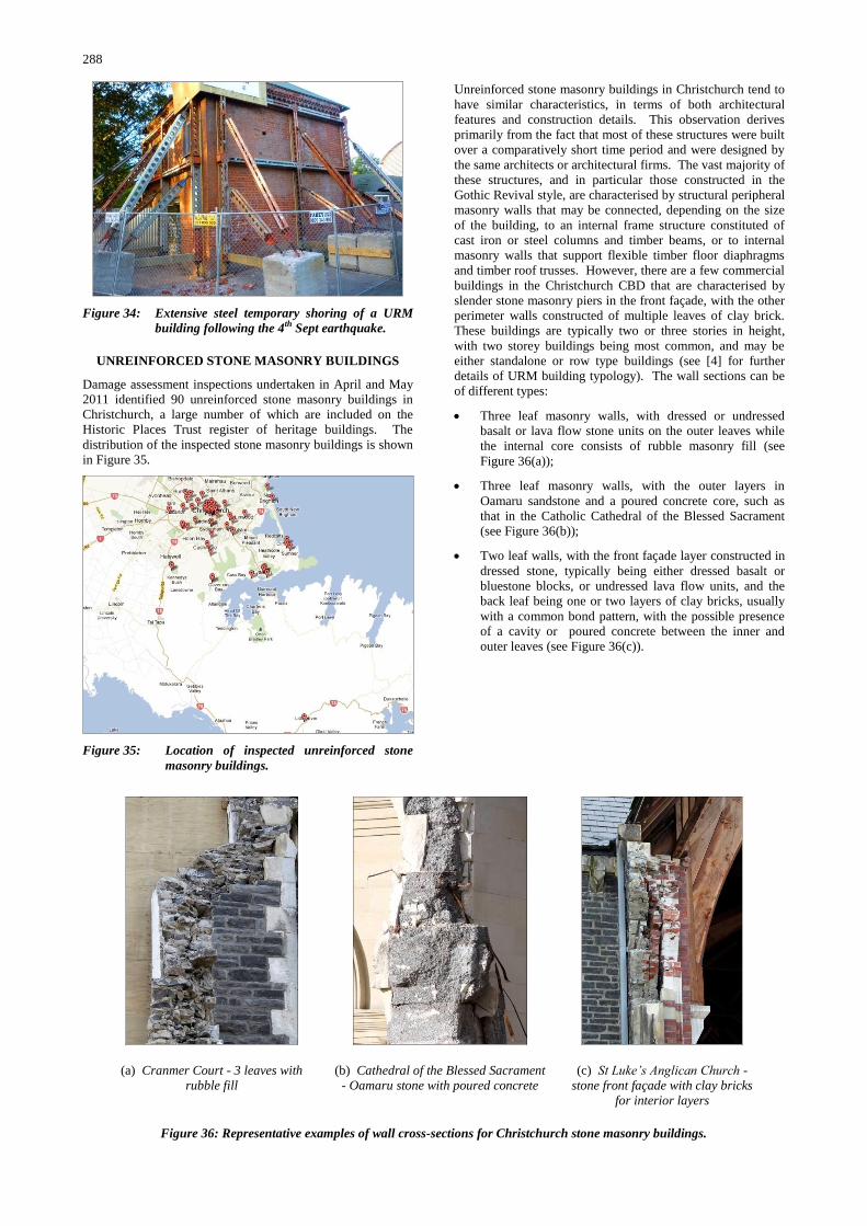
288
Figure 34: Extensive steel temporary shoring of a URM
building following the 4th Sept earthquake.
UNREINFORCED STONE MASONRY BUILDINGS
Damage assessment inspections undertaken in April and May
2011 identified 90 unreinforced stone masonry buildings in
Christchurch, a large number of which are included on the
Historic Places Trust register of heritage buildings. The
distribution of the inspected stone masonry buildings is shown
in Figure 35.
Figure 35: Location of inspected unreinforced stone
masonry buildings.
Unreinforced stone masonry buildings in Christchurch tend to
have similar characteristics, in terms of both architectural
features and construction details. This observation derives
primarily from the fact that most of these structures were built
over a comparatively short time period and were designed by
the same architects or architectural firms. The vast majority of
these structures, and in particular those constructed in the
Gothic Revival style, are characterised by structural peripheral
masonry walls that may be connected, depending on the size
of the building, to an internal frame structure constituted of
cast iron or steel columns and timber beams, or to internal
masonry walls that support flexible timber floor diaphragms
and timber roof trusses. However, there are a few commercial
buildings in the Christchurch CBD that are characterised by
slender stone masonry piers in the front façade, with the other
perimeter walls constructed of multiple leaves of clay brick.
These buildings are typically two or three stories in height,
with two storey buildings being most common, and may be
either standalone or row type buildings (see [4] for further
details of URM building typology). The wall sections can be
of different types:
Three leaf masonry walls, with dressed or undressed
basalt or lava flow stone units on the outer leaves while
the internal core consists of rubble masonry fill (see
Figure 36(a));
Three leaf masonry walls, with the outer layers in
Oamaru sandstone and a poured concrete core, such as
that in the Catholic Cathedral of the Blessed Sacrament
(see Figure 36(b));
Two leaf walls, with the front façade layer constructed in
dressed stone, typically being either dressed basalt or
bluestone blocks, or undressed lava flow units, and the
back leaf being one or two layers of clay bricks, usually
with a common bond pattern, with the possible presence
of a cavity or poured concrete between the inner and
outer leaves (see Figure 36(c)).
(a) Cranmer Court - 3 leaves with
rubble fill
(b) Cathedral of the Blessed Sacrament
- Oamaru stone with poured concrete
(c) St Luke’s Anglican Church -
stone front façade with clay bricks
for interior layers
Figure 36: Representative examples of wall cross-sections for Christchurch stone masonry buildings.

289
Damage Mechanisms in Stone Masonry Buildings
Out-of-plane failure mechanism
As expected for buildings with architectural features typical of
the Gothic Revival style (long span façades, flexible floor
diaphragms and weak connections between walls), partial or
global overturning or instability of the façades was reported
for most of the structures inspected, with damage ranging
from moderate to severe and in some cases reaching collapse.
Most buildings with out-of-plane failures appeared to have
poor connections between the walls at their corners, leading to
return wall separation and subsequent out-of-plane failure of
entire walls.
Many of the stone masonry buildings that were constructed in
the Gothic Revival style sustained damage to their gable ends,
with many observed cases of complete collapse of the gable.
The absence of significant gravity loads and inadequate
connection between the gable and roof trusses were primary
contributing factors to this gable end failure mode, along with
high accelerations experienced at the top levels of the
structure.
In-plane response of walls
As outlined previously, the 22nd February 2011 earthquake
appeared to have predominant shaking in the east-west
direction. This observation is further supported by in-plane
wall damage in the east-west running walls (see Figure 37) in
conjunction with overturning of façades oriented in the
orthogonal direction.
Figure 37: Canterbury Provincial Chambers - diagonal
crack through entire south façade of the east
annex.
Damage due to geometric irregularities
Damage that was attributable to plan irregularity was
frequently observed, particularly for stone churches, due to the
interaction between adjacent structural elements at the
intersections between walls. In most churches where the bell
tower or low annexes are connected to the nave, damage
developed at the intersection of the different structures. A
distinct example of damage due to plan irregularity in
association with differential foundation settlement was
observed at the former Old Boys‟ High building in the Arts
Centre.
Diaphragm and roof seismic response
Both adequate and inadequate securing of walls and
diaphragms using wall-diaphragm anchors was observed. In
some cases anchors were either absent or were spaced too far
apart to prevent bed joint shear failure of the masonry at the
location of the anchorage. In those cases where anchors had
been seismically designed, or anchors were sufficiently
closely spaced to resist lateral loads, the overturning of gables
and other portions of walls was prevented.
Two cases are presented to show the different behaviour
induced by the presence and effectiveness of anchorage.
Figure 38 shows the damage resulting from overturning of the
gable of the main façade of the former Trinity Church in the
Christchurch CBD, where anchors were insufficient in size
and spacing to secure the wall in place. Figure 39 shows an
example of successful wall-to-roof anchorage in an Arts
Centre building.
Figure 38: Former Trinity Church, showing details of gable
end out-of-plane wall failure.
Figure 39: The Christchurch Arts Centre, showing
successful use of wall-diaphragm
anchorages.
Damage induced by poor quality of construction materials
The quality of construction materials played a key role in the
response of stone URM buildings. As previously described,
one of the typical features of unreinforced stone masonry
buildings in Christchurch is the different types of stone and
mortar quality present in structures built with three-leaf walls.
The use of soft limestone, such as Oamaru stone or the red tuff
extracted in the Banks Peninsula, in conjunction with the use
of low strength lime mortar, often led to poor earthquake
response. Examples of such behaviour include the Holy
Trinity Church in Lyttelton, as illustrated in Figure 40.

290
Figure 40: Lyttelton Holy Trinity Church, showing damage
induced by movement of the roof.
RETROFIT INTERVENTIONS FOR STONE
MASONRY BUILDINGS
General Principles and Suggested Procedures
The poor seismic performance of unreinforced stone masonry
buildings in Christchurch is a reminder of the necessity to
seismically retrofit heritage buildings in an earthquake prone
country such as New Zealand. Suggestions for appropriate
strengthening principles and techniques should be gathered
from the experiences accumulated by researchers and
practitioners in other seismic areas of the world which have
stone masonry buildings with similar characteristics.
Retrofit interventions should improve the performance of the
structure as a complete entity, by eliminating or significantly
reducing structural deficiencies associated with design and
execution errors, and deterioration and damage. Issues
relating to both the vulnerability and the suitability of retrofit
interventions should be accounted for, with particularly
attention given to the effects of variations in stiffness between
elements and the stiffness changes associated with various
retrofit techniques. Strengthening interventions should
enhance the global behaviour of the structure and also the
performance of isolated structural elements, and should seek
to keep loads well distributed to avoid elevated stress levels.
Where necessary, interventions should address the possibility
of rocking and over-turning instability, and should support a
clearly defined load path through use of in-plane shear walls.
Furthermore, repair and retrofitting techniques should respect
the original structure in order to avoid incompatibility of both
materials and structural form.
Interventions should be regular and uniformly distributed on
the structure. The execution of strengthening interventions on
isolated parts of the building must be accurately evaluated
(with the aim of reducing or eliminating vulnerable elements
and structural irregularity) and justified by calculating the
effect in terms of the modified stiffness distribution.
Particular attention should be given to correct implementation
of the intervention strategy, as poor execution can cause
deterioration of masonry characteristics or worsening of the
global behaviour of the building, reducing the global ductility
capacity. Some examples of studies into the performance of
retrofit interventions are described in Binda et al. [11],
Vintzileou et al. [12], Valluzzi et al. [13], Valluzzi [14] and
Augenti & Parisi [15]. Different types of interventions are
suggested in well known Building Codes and Guidelines, such
as EC 8 [16], NTC [17], ASCE [18] or FEMA 547 [19].
These intervention types can be categorised as follows:
Improvement of floor to wall connections by the
introduction of anchoring ties, reinforcing ring beams and
floor-to-wall connections [19];
Improvement of the behaviour of arches and vaults,
through the installation of ties and extrados metallic
elements, or application of composite materials;
Reduction of excessive floor deformability (in-plane and
flexural stiffening with dry techniques, extrados
intervention with boarding, steel or Fibre Reinforced
Polymer (FRP) straps; bracing or other interventions at
the intrados);
Improvement of the roof or floor structures and the load
transfer fixings into the supporting walls;
Strengthening of masonry walls, either by local
rebuilding of walls, by grout injections, application of
anti-expulsive tie-rods (such as helical wall ties and
anchoring systems), repointing of the mortar joints
(reinforced repointing [20]), jacketing, insertion of
artificial through-stones, application of transverse tying
[21];
Improvement of pillars and columns, through measures
such as circumferential hoops and reinforced injections;
Improvement of connections to non-structural elements.
REINFORCED CONCRETE MASONRY
External evaluations of 471 concrete masonry buildings within
the Christchurch CBD were performed following the 22nd
February 2011 earthquake, with the location of these buildings
shown in Figure 41. The inspected buildings were classified
as one of three construction types: RCM solid wall
construction, RCM cavity wall construction, or reinforced
concrete (RC) frame with concrete masonry infill. Whilst the
observed damage to concrete masonry infill construction was
recorded, the reinforced concrete frame was considered to be
the principal structural system. Concrete masonry cavity wall
construction typically consisted of a 100 mm thick outer leaf
of concrete masonry block with an inner structural leaf of
RCM. Details of the 342 RCM buildings having solid wall
and cavity wall construction are summarised below.
Figure 41: Location of inspected RCM buildings.
The majority (83%) of RCM buildings had little or no damage
following the earthquake, as shown in Figure 42(a).
Nevertheless, exceptions to this good behaviour were
observed. The concrete masonry buildings damaged in the
earthquake exhibited diagonal in-plane shear cracking as the
primary failure mode, as shown in Figure 42(b). Diagonal in-
plane shear cracking included both step pattern cracking along
the head and bed mortar joints, and diagonal cracking through
masonry blocks. Vertical cracking of the block was also
commonly observed, followed less frequently by horizontal
cracking along bed joints and spalling of the block, typically
due to face shell blowouts, as shown in Figure 42(b). In
Figure 42(b) the „other‟ category includes failures due to

291
ground settlement, out-of-plane failures and full collapse of
simple elements.
(a) Damage Level of
RCM
(b) Failure Types of RCM
Figure 42: RCM inspected buildings.
Severe diagonal cracking of RCM shear walls in a multi-
storey commercial building in the central CBD was observed,
as shown in Figure 43. This building had a glass store front
with RCM shear walls in the N-S and E-W directions, as well
as an RCM elevator shaft. The reinforcement had insufficient
cover in places, causing face shell spalling of some concrete
masonry units.
(a) Severe diagonal shear
cracking of RCM shear walls
(b) Close-up of diagonal
shear cracking
Figure 43: Examples of diagonal shear cracking.
Similar diagonal shear cracking was observed in a five-storey
apartment complex having RCM cavity wall construction, as
shown in Figure 44. The diagonal crack pattern of the
100 mm external leaf was mirrored, although less extensively,
on the RCM internal leaf. This form of cavity construction
was somewhat unconventional as the external leaf was also
reinforced, although provided insufficient cover to the
reinforcement due to the narrow width of the concrete
masonry units (CMUs) used in the exterior leaf. Because of
the small void size in the exterior CMUs, in several locations
grout was observed to be discontinuous or honeycombed,
providing inadequate bond to the reinforcement. The damage
to this building was so severe that the building was scheduled
to be demolished. Similarly, of the severely damaged RCM
buildings where the grout and reinforcement were visible,
approximately fifty per cent had improper fill or incorrect
reinforcement placement.
More details of common construction deficiencies are shown
in Figure 45. Figure 45(a) shows a bond beam block in a
collapsed garage wall that was neither filled nor reinforced.
Figure 45(b) shows a collapsed RCM wall addition to a URM
building, in which the grout was not continuous even at the
top of the wall, leaving the reinforcement exposed. These
observations indicate that inadequate inspection procedures
exited at the time of construction. Observed damage to RCM
buildings suggests that design and detailing of piers around
openings also requires further attention. In buildings that
appeared to have adequate grouting and detailing, severe
failures mainly occurred in these elements.
Figure 44: Severe diagonal cracking of RCM cavity shear
wall.
(a) Poor cell grouting
(b) Ungrouted masonry cells
Figure 45: Examples of RCM construction deficiencies.
Several instances of structural damage in other inspected
RCM buildings suggest inadequate reinforcement detailing.
Various cases of lap-splices at plastic hinge locations showed
buckling of reinforcement bars. A large number of damaged
RCM walls showed vertical reinforcement near the ends of the
wall to be unconfined by horizontal reinforcement (see Figure
46(b)) as the horizontal reinforcement terminated prior to the
final vertical bar.
(a) Flexural failure of RCM wall
due to spalling and crushing of
grout
(b) Buckling of
unsupported lap-
spliced vertical
reinforcement
Figure 46: Damage to RCM shear walls following the
February 2011 earthquake.
RCM buildings with vertical cracking suffered only minor
damage. Several commercial buildings near the centre of the
CBD had RCM shear walls as side walls, with a glass store
frontage. These buildings frequently had vertical cracking at
the front ends of the RCM walls. Damage due to horizontal
cracking was again minor and generally occurred at either the
first course above or below a floor height. Finally, minor
diagonal cracking near openings was the most commonly
observed damage in RCM buildings.

292
Modelling of Case Study Buildings
Following the 22nd February 2011 earthquake, many cases of
existing midrise buildings of RCM construction achieved life
safety performance for a level of shaking beyond that
specified in the current New Zealand Loadings Standard [9].
Cases of severe structural damage to RCM buildings were
found in the vicinity of the CBD. As reported above,
structural damage to these buildings has been documented and
is currently being studied to establish the lessons which can be
learned from this earthquake and how to incorporate these
lessons into future RCM design and construction.
Among the cases being studied is a six storey RCM building
named Rollerston Courts that nearly collapsed and was
subsequently demolished. The RCM building consisted of a
ground floor for storage and parking that incorporated RC
walls, and apartments above having RCM shear walls, and an
RCM lift shaft. The interior RCM structural walls showed
damage due to flexure in the east-west direction, with face
shell spalling and grout crushing at the lower two courses in
the second storey, and diagonal cracking. These walls were
found to exhibit a flange effect due to the adjacent orthogonal
walls. Currently, an analytical model is being developed to
investigate the structural response of this building.
Another case study building is the New Zealand College of
Early Education, which was a four storey building with a
lateral system of RC shear wall lift shaft, RCM perimeter
walls, a gravity system consisting of RC circular columns,
RCM wall columns and precast RC beams. The damage
pattern and the offset location of the RC shear wall core
suggests a torsionally sensitive response. All gravity columns
in the building showed inelastic flexural damage, with
concrete cover spalling at the top of RC columns in all stories
and severe toe crushing and vertical splitting in RCM wall
columns. However, the external RCM wall sustained only
minimal damage. The RC shear wall core presented flexural
yielding cracks near the ground level. The mortar crack
patterns in the RCM shear walls adjacent to the RC shear wall
showed signs of yielding of the vertical reinforcement across
the height of the ground floor (see Figure 47). Two other
torsionally sensitive RCM buildings are also being studied.
Figure 47: Bed joint cracks indicating yielding of
reinforcement across the height of the first
floor.
CHURCHES
In the 1840‟s the rapidly increasing Canterbury population
from European settlement substantially increased the demand
for residential and community buildings. The first churches
built in Canterbury were mainly of timber frame construction,
due to the simplicity of construction and the availability of the
material. As the financial prosperity of the area developed,
stone and clay brick began to be used for the construction of
important and public buildings including churches.
Consequently timber, stone and clay brick masonry are the
most common construction materials used for church
construction in the Canterbury region. Examples of churches
constructed using these materials are shown in Figure 48.
Although less common, a number of churches were
constructed during the first quarter of the 20th century using
reinforced concrete, and combinations of the above materials
were also used.
(a) Timber church of St
Andrews, Merivale, 1857
(b) Stone church of St Peters,
Upper Riccarton, 1876
(c) Clay brick church of Our Lady Star of the Sea, Sumner, 1912
Figure 48: Representative churches found in the Canterbury
region.
Beginning in May 2011, earthquake damage of 112 churches
in the Canterbury region was inspected and assessed by a team
of researchers. The distribution of inspected churches in the
Canterbury region is shown in Figure 49. The inspection
procedure included recording the Civil Defence Placard
information assigned to churches during the immediate post-
earthquake safety evaluation, a detailed visual inspection of
the buildings‟ exterior, and in cases where permissible and
safe a detailed inspection of the buildings‟ interior, with
detailed photographic documentation of any damage.
Figure 49: Location of inspected churches.
Statistical Analysis
Figure 50(a) shows that the assessed churches can be
classified into three main categories according to the original
construction material: stone (28%), brick (19%), wood (42%),
and other (11%). Given the potentially different seismic
behaviour of the three construction types, a general analysis of
the placard classification (shown in Figure 50(b)) as
undertaken by the NZ Fire Service, Urban Search and Rescue
and volunteer engineers is potentially misleading.

293
(a) Church construction
material breakdown
(b) Overall church placard
classification
Figure 50: Construction type and damage for inspected
churches.
Figure 51(b) shows the distribution of the placard
classifications for the stone masonry churches, with over half
(52%) assigned a red placard. Also, the percentage of green
placards received for the stone masonry churches was the
smallest of the three church classifications.
Clay brick churches, as shown in Figure 51(a), had better
seismic performance than did stone masonry churches, with
red placards assigned to 38% of the churches and yellow
placards assigned to 43% of the total. The percentage of red
placards for this construction type is smaller than the
percentage for the stone masonry churches. However, the sum
of red and yellow placards is similar for the two construction
types and was over 80%.
Timber churches had the best overall performance, with none
of the assessed churches showing any type of structural
damage and, as can be seen in Figure 51(c), 94% were
assigned green placards. The only damage recorded to timber
churches was to non-structural elements. Internal plaster
damage, as shown in Figure 52, is an example of damage that
might limit the use of a timber church and result in a yellow
placard. All red placards assigned (2%) were due to external
causes (i.e. risk from a neighbouring building), where the
churches were structurally undamaged.
(a) Clay brick masonry
churches (b) Stone masonry churches
(c) Timber framed churches
Figure 51: Distribution of the placard classification for each
construction type.
The inspected churches, irrespective of the construction
material, followed a similar architectural style and
consequently presented similar possible collapse mechanisms.
Certain elements such as domes, vaults and chapels were
infrequently present, just as bell towers and presbyteries were
only found in a limited number of churches. Normally these
elements present a higher seismic vulnerability. Given this
finding, the dominant activated and most vulnerable collapse
mechanisms for the stone and clay brick masonry churches
were shear cracks along the longitudinal walls as shown in
Figure 53(a) and (b), and the overturning of façades and apses
as shown in Figure 53(c) and (d).
Figure 52: Damage to the internal plaster of St. Paul’s
Anglican Church, Harewood Road.
(a) Cathedral of the Blessed
Sacrament, shear
mechanism on the
longitudinal walls
(b) Nazareth’s House Church,
shear mechanism on the
longitudinal walls
(c) Rose Historic Chapel,
overturning of the top of the
whole façade
(d) Christchurch Chinese
Methodist Church,
overturning of the top of
the whole façade
Figure 53: Most commonly observed collapse mechanisms in
churches.
Timber framed churches share the architectural pattern of
stone and clay brick masonry churches, but the structural
characteristics of these buildings do not lead to activation of
the same collapse mechanisms. The lower structural mass
decreases the generated inertial forces and the global response
of the structure, which is characterised by integral response
rather than deforming as a set of elements, contributed to the
better seismic performance of the timber churches.
RESIDENTIAL MASONRY VENEER
Following the 2010/2011 Canterbury earthquakes a
comprehensive literature review and detailed door to door
assessments of residential masonry veneer dwellings were

294
conducted in a variety of areas of Christchurch. Specifically,
care was taken to include survey locations that had
experienced different levels of earthquake shaking, in order to
allow comparison between different system performances and
different shaking intensities. Following the 4th September
2010 Darfield earthquake little shaking damage was observed
to residential masonry veneers and observed damage was
instead due to foundation settlement, soil liquefaction and
lateral spreading. However, it was noted that newer, lighter
veneer systems appeared to perform better than older, heavier
systems.
Inspection Survey
In total just under 1,100 residential dwellings were inspected
throughout the wider Christchurch area (see Figure 54), of
which 24% were constructed using the older nail-on veneer tie
system (before 1996) and 76% were constructed using screw
fixed ties to comply with the new 1996 standards revision
(post-1996). 30% of all inspected houses were of two storey
construction. Of the inspected dwellings 27% had some
evidence of liquefaction, ground settlement or lateral
spreading. In areas where some form of liquefaction or lateral
spreading had occurred, the cause of damage for 40% of the
dwellings was attributed to ground movement only and 28%
of dwellings had damage that was attributed to shaking
damage only.
Figure 54: Location of inspected residential veneer
dwellings.
Severe (example shown in Figure 55) and extreme damage to
veneer dwellings was concentrated in the Port Hills and
foothills suburbs (13% of inspected dwellings) due to the
proximity to the epicentre as well as typographical
amplification of ground motions. It was also evident that the
majority of cases of severe and moderate damage were
concentrated close to the river banks (typically the residential
„Red Zone‟), mainly due to substantial liquefaction and lateral
spreading.
As expected, the level of damage increased with an increasing
level of ground acceleration. It was evident that severe and
extreme damage only occurred to veneers in areas of severe
peak ground acceleration (PGA) (0.62g – 1.3g) or extreme
(>1.3g) shaking. Of all inspected damaged dwellings, 60%
sustained in-plane damage only, with dwellings constructed
prior to 1996 being more likely to sustain out-of-plane damage
in comparison to dwellings constructed after 1996. Of all the
inspected dwellings which sustained some damage, 33% of
these dwellings had problems with corner separation. From
the survey it is evident that generally houses constructed since
the 1990s tended to suffer lower levels of damage than those
built earlier. It is evident that overall screw-fixed ties
performed better, with the majority of the dwellings where this
type of tie was used showing no visible or minor damage only.
It is apparent that damaged dwellings with nail-on ties
featured more predominantly in the moderate to extreme
damage categories, and it appears that wire ties performed the
worst as a higher proportion of inspected dwellings that had
wire type veneer ties sustained severe to extreme damage.
From the survey, it is evident that the use of Oamaru stone
veneer (and solid veneer units in general) performed the worst,
and a typical example of such performance is illustrated in
Figure 56.
Figure 55: Example of severe veneer damage level.
Figure 56: Poor performance of Oamaru stone veneer.
CONCLUSIONS
A brief summary of activities undertaken as part of Project
Masonry was presented, detailing the observations that were
made on the performance and the deficiencies that contributed
to the damage to unreinforced clay brick masonry buildings, to
unreinforced stone masonry buildings, to reinforced concrete
masonry buildings, to churches in the Canterbury region, and
to residential dwellings having external masonry veneer
cladding.
It was concluded that when subjected to the higher forces
generated by the earthquake on 22nd February 2011,
Christchurch‟s unreinforced masonry building stock
sustained much greater and more widespread damage than in
the 4th September 2010 earthquake. The damage modes
observed in September 2010 were again observed after
February 2011, together with additional modes. Chimney,
parapet and gable failures were again observed, along with
out-of-plane failures. Primary types of out-of-plane wall
failures that were observed were:
Cantilever type out-of-plane failure with the entire top
section of a wall or building façade collapsing;

295
One-way bending of the wall, which tended to occur in
longer walls or walls without side supports;
Two-way bending, which required support of at least
one vertical edge of a wall.
Damage in the plane of URM walls was widely observed
including:
Diagonal shear cracking in piers, spandrels and walls;
Shear sliding on mortar bed joints or between storeys;
In-plane rocking and toe crushing of piers.
Ground deformations were also observed to contribute to
building damage. Generally retrofit and temporary shoring
techniques prevented entire building collapse.
Cavity construction was encountered in almost half of the
URM buildings surveyed in Christchurch, with the remainder
having solid interconnected multi-leaf walls.
Common types of seismic retrofits observed in Christchurch
URM buildings were:
Steel moment frames, which increased the lateral
capacity of a building;
Steel strong-backs, which helped prevent out-of-plane
failure of URM walls;
Application of shotcrete, which increased the in-plane
and out-of-plane wall strength.
It was concluded that retrofits that generally performed well
were:
Well conceived designs which aimed to reduce torsional
effects and tied the masonry together;
Well connected steel strong backs and steel moment
frames.
Field observations revealed numerous cases where anchor
connections joining masonry walls or parapets with roof or
floor diaphragms appeared to have failed prematurely,
particularly for the case of adhesive anchors. In many cases
these failures were attributed to the low shear strength of
masonry, wide anchorage spacing, insufficient embedment
depth of anchors, and/or poor workmanship.
It was concluded that the successful performance of anchors
does not necessarily prevent out-of-plane wall failure, as the
potential for one or two way out-of-plane wall bending failure
is not necessarily precluded.
A total of 170 adhesive anchors were installed and tested to
identify the failure modes in existing masonry and to
determine the influence on anchor load-displacement response
for the following variables: type of adhesive, the strength of
the masonry materials (brick and mortar), anchor embedment
depth, anchor diameter, and use of metal foil sleeve.
Damage assessment of unreinforced stone masonry buildings
in Christchurch was conducted in April and May 2011 and
consequently the presented description of their seismic
response is based on observations made at that time.
Following the 13th June 2011 earthquakes and successive
aftershocks, the conditions of damaged heritage stone masonry
buildings continued to deteriorate, with more cases of partial
or complete collapse. Hence, the importance of earthquake
strengthening New Zealand‟s heritage masonry architecture to
preserve a key element of the nation‟s history continues to be
emphasised.
Following the 22nd February 2011 earthquake, many cases of
existing midrise buildings of RCM construction achieved life
safety performance for a level of shaking beyond that
specified in the current New Zealand Loadings Standard. In
the Christchurch CBD 342 RCM buildings (including RCM
buildings having veneer construction) were inspected and
evaluated. The majority of these buildings suffered little or no
damage, and in the remainder shear failure was the
predominant damage mode observed.
Cases of severe structural damage to RCM buildings were
found in the vicinity of the CBD. Structural damage to these
buildings has been documented and is currently being studied
to establish the lessons which can be learned from this
earthquake and how to incorporate these lessons into future
RCM design and construction.
Beginning in May 2011, earthquake damage of 112 churches
in the Canterbury region was inspected and assessed. The
assessed churches were classified into three main categories
according to the original construction material: stone (28%),
brick (19%), wood (42%) and other (11%). Given the
potentially different seismic behaviour of the three
construction types, a general analysis of the placard
classification undertaken by the NZ Fire Service, Urban
Search and Rescue and volunteer engineers was presented.
In total just under 1,100 residential dwellings were inspected
throughout the wider Christchurch area, of which 24% were
constructed using the older nail-on veneer tie system (before
1996) and 76% were constructed using screw fixed ties to
comply with the new 1996 standards revision (post-1996), and
where 30% of all inspected houses were of two storey
construction. Of the inspected dwellings 27% had some
evidence of liquefaction, ground settlement or lateral
spreading. In areas where some form of liquefaction or lateral
spreading had occurred, the cause of damage for 40% of the
dwellings was attributed to ground movement only and 28%
of dwellings had damage that was attributed to shaking
damage only.
Whilst it may be too late to save many of Christchurch‟s
historic clay brick and stone URM buildings, lessons learnt
from damage observations made during and after the
Canterbury earthquake swarm of 2010/2011 and future
detailed analysis of the collected data can be applied to
masonry buildings throughout the rest of New Zealand,
Australia, and around the world.
ACKNOWLEDGMENTS
The authors wish to thank the numerous professional
structural engineers and building owners who have provided
valuable data, opinions, expertise and their experiences. In
particular: John Hare, Stuart Oliver and others from Holmes
Consulting Group Ltd.; Paul Campbell, Will Parker and others
from Opus International Consultants Ltd.; Win Clark, Cecil
DelaRue, Fiona Wykes and others from the Civil Defence
Heritage team; Hossein Derakhashan and others from Aurecon
New Zealand Ltd.; Andrew Marriot and others from Marriot
Consulting Engineers Ltd.; and URS Consulting Ltd.
The authors thank Ronald Lumantarna for conducting and
providing mortar and clay brick compression strength results.
EQ STRUC Ltd. is thanked for providing expertise and test
equipment and Hilti (NZ) Ltd., Reids Construction Systems
Ltd and Sika (NZ) Ltd. are thanked for proving materials in
order to conduct in-field anchor pull-out tests.
Darryl and Alistair from the Civil Defence demolition team,
Graceworks Demolition, Ward Demolition, Southern
Demolition, Nikau Demolition, and other demolition
companies are thanked for allowing site investigation and
access for sample collection during demolition of damaged
buildings.

296
Stephanie German and Jazalyn Dukes from Georgia Institute
of Technology, Benoit Rozier from Ecole Nationale des
Travaux Publics de l‟Etat in Lyon, France, Will Cyrier from
Washington State University and Chaminda Konthesingha
from the University of Newcastle are also thanked for their
assistance and contributions.
The authors acknowledge the financial support for Project
Masonry from the New Zealand Natural Hazards Research
Platform. The testing of adhesive anchors was undertaken in
conjunction with the RAPID grant CMMI-1138614 from the
US National Science Foundation. The investigation of the
performance of residential brick veneers was financially
supported by Brickworks Building Products Australia.
REFERENCES
1. GeoNet. (2010). M 7.1, Darfield (Canterbury), September
4 2010. Retrieved on 12th July 2011. Available from:
http://www.geonet.org.nz/earthquake/historic-
earthquakes/top-nz/quake-13.html
2. GeoNet. (2011). Feb M 6.3, Christchurch, February 22
2011. Retrieved on 12th July 2011 Available from:
http://www.geonet.org.nz/earthquake/historic-
earthquakes/top-nz/quake-14.html
3. IPENZ. (2011). Christchurch Earthquake Fact Sheets.
Retrieved on 12th July 2011
http://www.ipenz.org.nz/ipenz/forms/pdfs/ChChFactShee
ts-Overview.pdf
4. Russell, A. P. & Ingham, J. M. (2010). “Prevalence of
New Zealand‟s Unreinforced Masonry Buildings”,
Bulletin of the New Zealand Society for Earthquake
Engineering, Vol. 43, No. 3, pp. 182-201.
5. Dizhur, D., Ismail, N., Knox, C., Lumantarna, R. &
Ingham, J. (2010). “Performance of unreinforced and
retrofitted masonry buildings during the 2010 Darfield
earthquake”, Bulletin of the New Zealand Society for
Earthquake Engineering, Vol. 43 No. 4, pp. 321-339.
6. Ingham, J. & Griffith, M. (2011). “Performance of
unreinforced masonry buildings during the 2010 Darfield
(Christchurch, NZ) earthquake”, Australian Journal of
Structural Engineering, Vol. 11, No. 3, pp. 207-224.
7. Canterbury Earthquake Recovery Authority (CERA)
(2011). Demolition Lists. Retrieved on 26th July 2011.
Available from www.cera.govt.nz/demolitions/list
8. Dizhur, D., Ingham, J. & Griffith, M. (2010). “The
performance of unreinforced masonry chimneys in the
2010 Darfield Earthquake”, NZSEE Clearing House.
Retrieved on 12th July 2011. Available from:
http://db.nzsee.org.nz:8080/documents/10533/5332db95-
32f8-47ab-b1af-bfde01f6d9b3
9. SNZ (2002) “NZS 1170.0:2002 Structural design actions
– New Zealand.” Standards New Zealand.
10. ASTM. (2003). “Standard Test Methods for Strength of
Anchors in Concrete and Masonry Elements” E488-96,
ASTM International, Pennsylvania, United States.
11. Binda, L., Modena, C., Baronio, G. & Gelmi, A. (1994).
“Experimental qualification of injection admixtures used
for repair and strengthening of stone masonry walls”, 10th
Int. Brick/Block Masonry Conf., Calgary, Vol. 2, pp.
539-548.
12. Vintzileou, E. & Tassios, T. P. (1995). “Three-leaf stone
masonry strengthened by injecting cement grouts”,
Journal of Structural Engineering, Vol. 121, No. 5, pp.
848-856.
13. Valluzzi, M. R., da Porto, F. & Modena, C. (2004).
“Behavior and modeling of strengthened three-leaf stone
masonry walls”, Materials and Structure, Vol. 37, No. 3,
pp. 184-192.
14. Valluzzi, M. R. (2007). “On the vulnerability of historical
masonry structures: analysis and mitigation”, Materials
and Structures, Vol. 40, No. 7, pp. 723–743.
15. Augenti, N. & Parisi, F. (2010). “Learning from
construction failures due to the 2009 L‟Aquila, Italy,
Earthquake”, Journal of Performance of Constructed
Facilities, Vol. 24, No. 6, pp. 536-555.
16. EC 8 (2005). “Eurocode 8: Design of structures for
earthquake resistance, Part 3: Assessment and retrofitting
of buildings”, CEN–EN 1998-3.
17. NTC (2008). “NTC 2008 - Norme tecniche per le
costruzioni” (in Italian), Ministerial Decree and
Commentary, 14/01/2008, Italy.
18. ASCE (2006). Seismic Rehabilitation of Existing
Buildings – SEI/ASCE 41-06. American Society of Civil
Engineers, Reston, Va.
19. FEMA 547 (2006). Techniques for the seismic
rehabilitation of existing buildings, Federal Emergency
Management Agency, Washington, DC.
20. Borri, A., Corradi, M., Speranzini, E. & Giannantoni, A.
(2008). “Consolidation and Reinforcing of stone wall
using a reinforced repointing grid”, 6th International
Conference of Structural Analysis of Historical
Construction, 2-4 July, Bath, England.
21. Dolce, M., Nigro, D., Ponzo, F. C. & Marnetto,. R.
(2001). “The CAM system for the retrofit of masonry
structures”, Proceedings of the 7th International Seminar
on Seismic Isolation, Passive Energy Dissipation and
Active Control of Vibrations of Structures, Assisi, Italy.