Embed Size (px)
Citation preview
1
May 14, 2008
IEEE PSRC, WG C12
Performance of Relaying during Wide-Area Stressed Conditions
Assignment:
To create a working group report and a summary IEEE paper that will describe the performance of protective relays during wide-area stressed power system conditions. The work will not cover System Integrity Protection Schemes (SIPS).
Members:
D. Novosel (chair); G. Bartok (vice-chair); A. Apostolov; M. Begovic; K. Behrendt; G. Benmouyal; M. Bloder; S. Brahma, G. Brunello; A. Buanno; F. Calero; M. Carpenter; J. De La Ree; A. Deronja; W. Elmore, J. Gardell, W. Hartmann; G. Henneberg, S. Horowitz; S. Imai; A. Johnson; B. Kasztenny; B. Kennedy; P. Kerrigan; S. Kim; C.W. Liu; V. Madani; P.Mysore; S. Saygin, M. Shah; J. Soehren; V. Terzija, D. Tziouvaras; M. Venkata; S.Ward; D. Ware; T. Wiedman; B. Wojszczyk
2
TABLE OF CONTENTS
1 Introduction.......................................................................................................................................... 5
1.1 References ................................................................................................................................... 5
2 Summary Description of Key Phenomena........................................................................................ 6
2.1 Voltage Instability........................................................................................................................ 6 2.1.1 Phenomenon Description ................................................................................................... 6 2.1.2 Protection against Voltage Instabilities ............................................................................ 7 2.1.3 References ......................................................................................................................... 10
2.2 Voltage Excursions ................................................................................................................... 11 2.2.1 Long-term Variations ........................................................................................................ 11 2.2.2 Short-term Variations........................................................................................................ 11
2.3 Angular Instability ..................................................................................................................... 12 2.3.1 Power Transfer between Two Equivalent Sources ........................................................ 13 2.3.2 The Power Angle Curve .................................................................................................... 13 2.3.3 Transmission Line Impedances during Faults ............................................................... 14 2.3.4 Transiently Stable and Unstable Systems ...................................................................... 15 2.3.5 Power Swing Protection Philosophy............................................................................... 16 2.3.6 References ......................................................................................................................... 18
2.4 Small-Signal Instability ............................................................................................................. 18 2.4.1 References ......................................................................................................................... 19
2.5 High Equipment Loadings and High Power Transfers .......................................................... 19 2.5.1 Cold Load Pickup .............................................................................................................. 20
2.6 Frequency Excursions .............................................................................................................. 20 2.7 High System Unbalance............................................................................................................ 21
2.7.1 References ......................................................................................................................... 22
3 Protection Related Behavior Under Stressed Conditions............................................................. 23
3.1 Impact of Off-nominal Frequencies on Phasors .................................................................... 23 3.2 Transmission Line Protection.................................................................................................. 25
3.2.1 Effect of Angular Instability on Transmission Line Protection .................................... 25 3.2.2 Automatic Reclosing and Synchro-check ...................................................................... 26 3.2.3 Line Distance Protection .................................................................................................. 26 3.2.4 Line Differential Protection............................................................................................... 31 3.2.5 Tripping of Ground Over-current Element Caused by Dynamic Line Loading........... 32 3.2.6 Series Compensated Lines............................................................................................... 33 3.2.7 Parallel Lines...................................................................................................................... 34 3.2.8 Multi-Terminal and Tapped Lines .................................................................................... 34 3.2.9 References ......................................................................................................................... 36
3.3 Transformer Protection............................................................................................................. 37 3.3.1 Differential Protection ....................................................................................................... 37 3.3.2 References ......................................................................................................................... 40
3.4 Generator Protection................................................................................................................. 41 3.4.1 Under-voltage..................................................................................................................... 41 3.4.2 Backup Protection............................................................................................................. 41 3.4.3 Incorrect Tripping on Load Rejection.............................................................................. 41 3.4.4 Under-frequency................................................................................................................ 41 3.4.5 Loss of Field....................................................................................................................... 41 3.4.6 Over-Excitation .................................................................................................................. 41 3.4.7 Out-of-Step ......................................................................................................................... 42 3.4.8 Gas Turbine Generator Motoring ..................................................................................... 42
3
3.4.9 Unknown Causes............................................................................................................... 42 3.4.10 References ......................................................................................................................... 42
3.5 Bus Protection ........................................................................................................................... 42 3.6 Shunt Capacitor and Reactor Protection ................................................................................ 43 3.7 Feeder Protection ...................................................................................................................... 43 3.8 Motor Protection........................................................................................................................ 44
3.8.1 Under-voltage..................................................................................................................... 44 3.8.2 Under-frequency................................................................................................................ 44 3.8.3 Over-voltage....................................................................................................................... 45 3.8.4 References ......................................................................................................................... 45
3.9 Under-frequency Load Shedding Protection.......................................................................... 45 3.9.1 References ......................................................................................................................... 46
3.10 System Integrity Protection Scheme (SIPS) ........................................................................... 46 3.10.1 References ......................................................................................................................... 47
3.11 Dependability and Security Balance ....................................................................................... 47
4 Field Experience and Examples....................................................................................................... 48
4.1 North American Electric Reliability Council (NERC) Analysis of August 14, 2003 Blackout48 4.1.1 Loadability Requirements................................................................................................. 49 4.1.2 Under-frequency Relaying Issues.................................................................................... 51 4.1.3 Monitoring System Issues ................................................................................................ 52 4.1.4 Generator Protection Issues ............................................................................................ 52
4.2 Other Blackouts......................................................................................................................... 52 4.2.1 Northeast Blackout-Nov 9, 1965....................................................................................... 53 4.2.2 PJM Blackout, June 5, 1967 10:18 a.m. ........................................................................... 53 4.2.3 New York City Blackout - July 13-14, 1977 ..................................................................... 53 4.2.4 French Blackout - December 19, 1978............................................................................. 53 4.2.5 Tokyo – July 23, 1987: Impact of Voltage Stability on Distance Protection................ 54 4.2.6 Western U.S. Outage - July 2, 1996 ................................................................................. 55 4.2.7 Sweden and Denmark - September 23, 2003 .................................................................. 55 4.2.8 Italy-September 28, 2003................................................................................................... 55 4.2.9 References ......................................................................................................................... 55
4.3 Device Records Example.......................................................................................................... 56 4.3.1 Line Trip during a Power System Cascade..................................................................... 56
5 Solutions ............................................................................................................................................ 57
5.1 Frequency Tracking and Compensation................................................................................. 57 5.2 Transmission Lines................................................................................................................... 57
5.2.1 Angular Instability ............................................................................................................. 58 5.2.2 Automatic Reclosing and Synchro-check ...................................................................... 62 5.2.3 Thermal Modeling and Measurement .............................................................................. 63 5.2.4 Line Distance Protection .................................................................................................. 63 5.2.5 Line Differential Protection............................................................................................... 66 5.2.6 Ground Over-current ......................................................................................................... 66 5.2.7 Series Compensated Lines............................................................................................... 67 5.2.8 Parallel Lines...................................................................................................................... 67 5.2.9 Multi-Terminal and Tapped Lines .................................................................................... 67 5.2.10 References ......................................................................................................................... 70
5.3 Transformer Protection............................................................................................................. 70 5.4 Generator Protection................................................................................................................. 70
5.4.1 Abnormal Voltage Protection ........................................................................................... 70 5.4.2 System Phase Backup ...................................................................................................... 71 5.4.3 Under-frequency................................................................................................................ 71 5.4.4 Loss of Field (LOF) ............................................................................................................ 71 5.4.5 Over-Excitation .................................................................................................................. 72 5.4.6 Out of Step ......................................................................................................................... 72
4
5.4.7 Gas Turbine Generator Reverse Power Protection........................................................ 72 5.5 Bus Protection ........................................................................................................................... 72
5.5.1 References ......................................................................................................................... 73 5.6 Shunt Reactor/Capacitor Protection ....................................................................................... 73 5.7 Feeder Protection ...................................................................................................................... 73 5.8 Motor Protection........................................................................................................................ 74 5.9 Under-frequency Load Shedding Protection.......................................................................... 74
5.9.1 References ......................................................................................................................... 75 5.10 Important Aspects of Improving Protection Performance .................................................... 75
5.10.1 Protection scheme design................................................................................................ 75 5.10.2 Hidden failures................................................................................................................... 75 5.10.3 Human errors ..................................................................................................................... 76 5.10.4 References ......................................................................................................................... 76
6 Conclusions ....................................................................................................................................... 77
7 Appendix A: Three Terminal Lines: Equations and Examples ..................................................... 78
5
1 Introduction
Recent wide-area electrical disturbances have clearly demonstrated the vulnerability of the interconnected power system when operated outside its intended design limits and have shown that protective relay systems are very often involved in major wide area perturbations [1.1.1] [1.1.2]. The relay systems sometimes prevent further propagation and sometimes contribute to the spread of the disturbance.
Protective devices play a vital role in protecting equipment and the surrounding systems from major damages or catastrophic failures. Therefore, proper implementation is the key to maintaining service continuity while limiting damage to apparatus and avoiding other intolerable conditions. Protective devices are also set for conditions beyond normal and steady state, as these devices must be available to handle intolerable system conditions to avoid serious outages and damage. In theory, protective devices are expected to respond to an infinite number of power system contingencies. In practice, power system engineers use the following factors that influence protection applications and set points:
• Initiate actions only for the intended purpose and for the equipment and/or zone designed to be protected
• Standardization of criteria for application, set points derivations, and coordination
• Operating practices to achieve required system operation
• Previous experience and anticipation of the types of trouble likely to be encountered within the system for which the protection is expected to perform accurately
• Costs: initial capital, operating, and maintenance
Hence, protection applications include a balance of many factors. A factor that has recently been under scrutiny is the protection performance during stressed system conditions. A number of protection aspects are affected by wide-area perturbations, such as:
• Relay settings and coordination, e.g. protection system performance under conditions for which relay setting criteria have not been developed (multiple contingencies, stressed system conditions as a result of operating the system close to the limit, etc.)
• Design of various protection schemes
• Hidden failures
• Energy and market strategies
In this report, the role of protection systems in wide-area disturbances is reviewed. Firstly, the behavior of protection functions during dynamic operating conditions is described. Secondly, the lessons learned from studying recent wide area perturbations, as well as the operational history of protection performance during stressed system conditions, are analyzed. Finally, methods of implementing protective relay functions to prevent further propagation of system-wide disturbances are presented. The following issues are addressed for analyzed relaying schemes:
• Performance
• Equipment rating
• Settings and coordination
• Dependability vs. security
• Maintenance and testing
1.1 References
[1.1.1] NERC Recommendations to August 14, 2003 Blackout - Prevent and Mitigate the Impacts of Future Cascading Blackouts; www.NERC.com .
[1.1.2] D. Novosel, M. Begovic, and V. Madani, “Shedding Light on Blackouts,” IEEE Power and Energy Magazine, January/February 2004.
6
2 Summary Description of Key Phenomena
Generally, disturbance propagation involves a combination of the phenomena listed below:
• Voltage instability/collapse
• Voltage excursions
• Angular instability
• Small-signal instability
• High equipment loadings and high power transfers
• Frequency excursions due to imbalance in active power between generation and load
• High system unbalance
These phenomena are described in more detail next.
2.1 Voltage Instability
Voltage stability (VS) is defined by the System Dynamic Performance Subcommittee of the IEEE Power System Engineering Committee [2.1. 1] as the ability of a system to maintain voltage such that when load admittance is increased, load power will increase, and so that both power and voltage are controllable. Also, voltage collapse is defined as being the process by which voltage instability leads to a very low voltage profile in a significant part of the system. It is accepted that voltage instability is load-driven, as opposed to transient (angular) instability, which is generator-driven.
The risk of voltage instability increases as the transmission system becomes more heavily loaded. The typical scenario of these instabilities starts with a high system loading, followed by a protective relay tripping due to a fault, a line overload and/ or a generator hitting an excitation limit. The consequences of voltage collapse often require long system restoration, while large groups of customers are left without a supply for extended periods of time.
Voltage instability can be alleviated by a combination of the following remedial measures: adding reactive compensation near load centers, strengthening the transmission lines, varying the operating conditions such as voltage profile and generation dispatch, coordinating relays and controls, and load shedding. Most utilities rely on planning and operating studies to guard against voltage instability. Many utilities utilize local voltage measurements in order to design load shedding schemes as a measure against incipient voltage instability [2.1.2].
2.1.1 Phenomenon Description
Several distinguishing features typically manifest voltage instability: low system voltage profiles, heavy reactive line flows, inadequate reactive support, heavily loaded power systems. Voltage collapse typically occurs abruptly, after a symptomatic period that may last from a few seconds to several minutes, sometimes hours. The onset of voltage collapse is often precipitated by low-probability single or multiple contingencies. Studying voltage collapse requires the complementary use of dynamic and static analysis techniques.
Dynamic analysis of the system provides an insight into the time responses of the system; such as determination of the time sequence of the different events leading to system voltage instability, especially following fast disturbances of the system structure, which may involve equipment outages, or faults followed by equipment outages. Long-term dynamic simulations, either with detailed dynamic modeling or simplified modeling, allow an accurate assessment of critical power system problems. However, time-domain simulations are time consuming (in terms of CPU) and, therefore, impractical when considering a large number of scenarios and contingencies. In addition, dynamic analysis does not readily provide information regarding the sensitivity or degree of the system instability.
If the system parameters change slowly (for example, fluctuations of the system load), they cause the stable equilibrium of the system to move slowly, which makes it possible to approximate voltage profile changes by a discrete sequence of steady states. In other words, static (steady-state) analysis of the
7
system is quite appropriate. Static analysis may include power flow methods, sensitivity analysis, as well as traditional local analysis (e.g., P-V and Q-V curves).
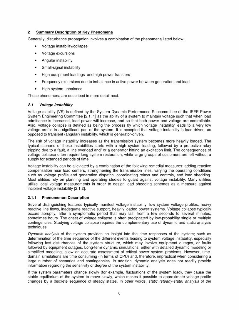
Figure 2.1 shows a trajectory of the load voltage V when active (P) and reactive (Q) power change slowly and independently. This figure also shows the active and reactive power margins as projections of the distances. The voltage stability boundary is represented by a projection onto the PQ plane (a bold curve). It can be observed that: i) there may be many possible trajectories to (and points of) voltage collapse; ii) active and reactive power margins depend on the initial operating point and the trajectory to collapse.
P
Q
Vtrajectory (P,Q,V)
point of voltage
collapse
an operating point
active power
margin
reactive power margin
Figure 2.1 Voltage Instability
Figure 2.1 shows a symbolic depiction of the process of coalescing of the stable and unstable power system equilibriums (SNB) through slow load variations, which leads to a voltage collapse (a precipitous departure of the system state along the center manifold at the moment of coalescing). The VPQ curve represents the trajectory of the load voltage, V, of a 2-bus system model when the active (P) and the reactive (Q) power of the load can change arbitrarily.
2.1.2 Protection against Voltage Instabilities
Voltage instabilities are often investigated using a static bifurcation model. In recent years, significant attention has been given to the methods that use direct parametric (load) dependence to estimate the proximity of a power system to the voltage collapse.
Some authors [2.1.11] [2.112] propose phasor measurement-based algorithms to determine voltage collapse proximity. This concept is attractive, since the technology for synchronized, real-time measurements of voltage as well as all incident current phasors at the system buses, is already available in the form of phasor measurements from phasor measurement units (PMUs). Voltage phasors contain enough information to detect the voltage stability margin directly from their measurements. The voltage stability condition is derived from the two-bus equivalent of the systems calculated in real-time, assuming constant power loads. It suggests that in the critical condition, the two-bus equivalent generator voltage phasor is twice as large as the projection of the load bus voltage onto it. The proposed algorithms for the determination of a two-bus equivalent differ. A typical example is presented in the following text.
The local voltage stability monitoring and control, at the every time instant tk, are based on a time-
dependent two-bus equivalent, which consists of the generator kE that supplies local load , ,L k L kP jQ+
over the branch k k kZ R jX= + , as shown in Fig. 2.2.
8
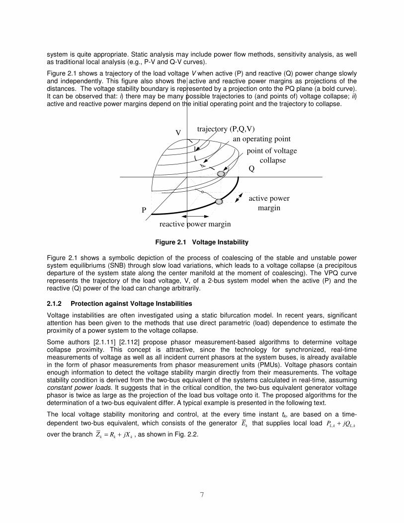
Figure 2.2 Load bus and the rest of the system represented as a voltage source and a transmission line, and the corresponding phasor diagram
The parameters of the voltage source kE and line kZ modeling the rest of the system, as seen from the
local bus at tk, are estimated from the time sequence of voltage and current phasor measurements at the bus.
When a load is of the constant power type, a simple calculation shows that the voltage instability point coincides with the point of maximum power transfer, producing the relationship between the voltage of an equivalent voltage source Ek and the voltage at a local load bus Vk as follows:
2 cosk k kE V θ= .
Under maximum power conditions, the voltage drop, kV∆ , across the transmission impedance, kZ , is
equal to the load bus voltage, Vk , (see the voltage phasor diagram in 2.2).
k kV V∆ = .
Therefore, to assess the risk of voltage collapse in the presence of constant power loads, the Voltage Stability Load Bus Index (VSLBI) needs to be monitored.
k
k
k
VVSLBI
V=
∆
A VSLBIk value close to one is indicative of a proximity to voltage collapse. It reaches unity when the power transfer through Zk becomes unstable for a voltage collapse. The smallest value among all voltage stability load bus indices, VSLBIk, at a time instant, tk, gives the voltage stability index, VSIk, of the whole system
{ },minPQ
k i ki
VSI VSLBIα∈
=
where i denotes the load bus index, and αPQ represents a set of the system load buses. Comparison ofVSLBIk values provides information on the relative vulnerability of various buses, which can be used for remedial actions.
The two main causes of reactive power reaching a limit in a generator are the excitation current limit and the armature thermal limit. The potentially adverse effects of generator reactive capability limits on voltage stability are well known. For heavy loading conditions, the reactive power produced by the generator increases with the load to maintain its terminal voltage, and when it reaches its limit, the generator loses voltage control, and switches from PV to PQ mode of operation. At the transition points, VSI changes abruptly. The consequences of the PV-PQ transitions are hard to predict, because they introduce the discontinuities in the model. As the system moves closer to the stability limit and VSI approaches unity, the PV-PQ transitions become more dangerous. Therefore, it is necessary to monitor the system reactive power reserves, and to deploy protective/control actions if the reserves are nearly exhausted and VSI is below a certain threshold.
The PV-PQ transition of generator i can be estimated by monitoring its reactive power reserve max
,i ig g kQ Q− , where the generator reactive power output at a time instant tk is modeled as a nonlinear
function of time that fits a sliding window of data samples. For the sake of illustration, let us assume that the model is linear, and estimate the time instant at which the reactive power of unit i will be exhausted as
9
max
,*
, /
i i
i
g g k
gi k
g k k
Q Qt t
Q t
−= +
∆ ∆
where tk denotes the current time instant, while , /ig k kQ t∆ ∆ represents the rate of change of reactive power
generated by unit i, which is calculated from two consecutive measurements. Therefore, the occurrence of the next PV-PQ transition in the system is estimated by
* *min{ }
PV
g gii
t tα∈
=
where αPV represents a set of generator units operating in the PV mode. The time remaining to the next PV-PQ transition represents the Reactive Power Reserve Index RPRI:
{ }*min
PV
k gi ki
RPRI t tα∈
= −
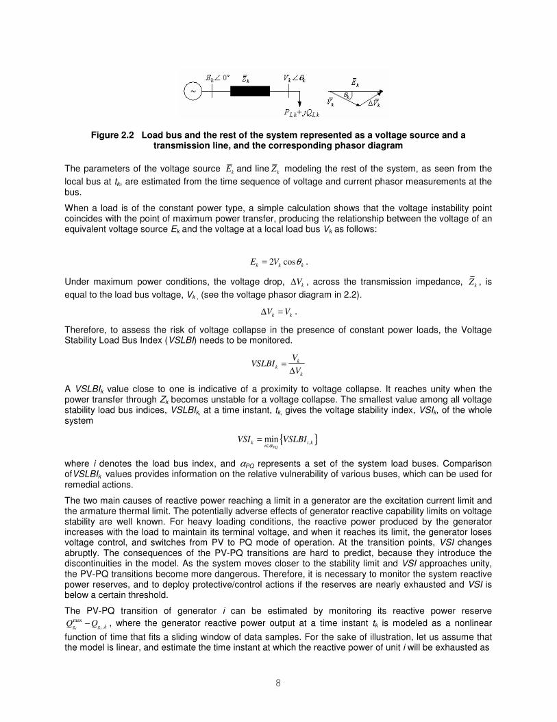
Every time the value of RPRIk becomes close to zero, a generator may reach its reactive power limit. Fig. 2.3 shows RPRI for the 39-bus system. Between the initial and the critical loading, the RPRI reached the value of zero six times indicating that six generator units reached their reactive power limits.
0
15
30
45
60
75
90
105
0 30 60 90 120 150t (min)
RP
RI
(min
)
Figure 2.3 Reactive power reserve indicator (RPRI) for the IEEE 39-bus system with 75% P and 25% Z load
A VSI value below a certain threshold, (e.g. VSI< 2) and an RPRI value close to zero, would predict a voltage collapse. These parameters represent a trigger for the control activation at a certain bus.
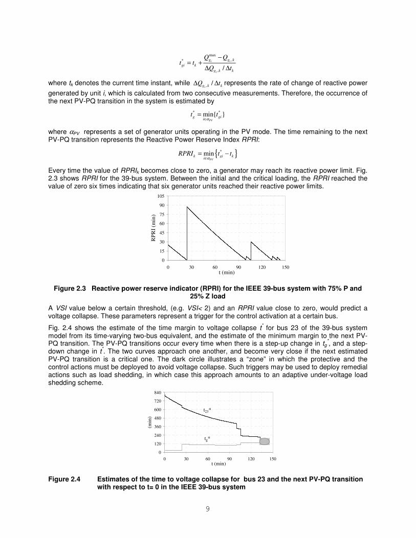
Fig. 2.4 shows the estimate of the time margin to voltage collapse t* for bus 23 of the 39-bus system
model from its time-varying two-bus equivalent, and the estimate of the minimum margin to the next PV-PQ transition. The PV-PQ transitions occur every time when there is a step-up change in tg
*, and a step-
down change in t*. The two curves approach one another, and become very close if the next estimated
PV-PQ transition is a critical one. The dark circle illustrates a “zone” in which the protective and the control actions must be deployed to avoid voltage collapse. Such triggers may be used to deploy remedial actions such as load shedding, in which case this approach amounts to an adaptive under-voltage load shedding scheme.
0
120
240
360
480
600
720
840
0 30 60 90 120 150t (min)
(min
)
t23*
tg*
Figure 2.4 Estimates of the time to voltage collapse for bus 23 and the next PV-PQ transition with respect to t= 0 in the IEEE 39-bus system
10
The control actions in the vicinity of the critical bus may be: i) activation of the available reactive power reserves, ii) blocking of the tap changers, iii) voltage reduction at the feeders connected to the corresponding and the neighboring buses, or iv) load shedding of the nearest consumers if the above measures do not prove to be effective.
The onset of the voltage collapse point to current operating conditions is therefore determined based on both the VLSBI indicator calculated from the local voltage and the current phasors measurements, and the system-wide information on reactive power reserves. The algorithm suggests that control actions be deployed when the stability margin is small and the reactive power reserves are nearly exhausted. Namely, limitations in reactive power generation cause sudden changes in the VLBSI, and prevent the operator from acting in time. This problem is more emphasized as voltage dependent loads represent a greater portion of the total load. For these reasons, by considering the VLBSI value only, a decision cannot be made on the triggering of protective/emergency controls. The decision needs to be revised by using the information on generator reactive reserves. The proposed concept for voltage stability protection and control does not jeopardize the existing protection systems. On the contrary, it is added to the existing control schemes to provide this additional function.
2.1.3 References
[2.1. 1] Voltage Stability of Power Systems: Concepts, Analytical Tools, and Industry Experience, IEEE Publication, 90TH0358-2-PWR, 1990.
[2.1.2] System Protection and Voltage Stability, IEEE Power System Relaying Committee, IEEE Publication, 93THO596-7 PWR, 1993.
[2.1.3] J. Jarjis, F.D. Galiana, “Quantitative Analysis of Steady State Stability in Power Networks”, IEEE Trans. On Power Apparatus and Systems, Vol. PAS-100, No. 1, Jan. 1981.
[2.1.4] I. Dobson, “Computing a Closest Bifurcation Instability in Multidimensional Parameter space”, Journal of Nonlinear Science, Feb. 1992.
[2.1.5] I. Dobson, L. Liming, “New Methods for Computing a Closest Saddle Node Bifurcation and Worst Case Load Power Margin for Voltage Collapse”, IEEE Transaction on Power Systems, Vol. 8, No.3, August 1993.
[2.1.6] V. Ajjarapu, C.Christy, “The Continuation Power Flow: A Tool for Steady State Voltage Stability Analysis”, IEEE Transaction on Power Systems, Vol. 7, No. 1, February 1992.
[2.1.7] R.J. Jumeau, H.D. Chiang, “Parameterization of the Load-Flow Equations for Eliminating Ill-conditioning Load Flow Solutions”, IEEE Transaction on Power Systems, Vol. 8 No. 3 February 1993.
[2.1.8] I. Dobson, “The irrelevance of load dynamics for the loading margin to voltage collapse and its sensitivities”, Bulk Power System Phenomena – III: Voltage Stability, Security and Control, Switzerland, Aug. 1994.
[2.1.9] F. Gubina and B. Strmčnik, “Voltage collapse proximity index determination using voltage phasor approach”, IEEE Trans. on Power Systems, vol. 10, no.2, pp. 788-793, May 1995.
[2.1.10] K. Vu, M. M. Begovic, and D. Novosel, M.M. Saha, “Use of local measurements to estimate voltage-stability margin”, IEEE Trans. on Power Systems, vol. 14, no. 3, Aug. 1999.
[2.1.11] Begovic, M., Milisavljevic, M., Novosel, D., "Trends in Power System Protection and Control," Elsevier Journal of Decision Support Systems, Vol. 3, No. 30, pp. 269–278, 2001.
[2.1.12] Milosevic, B., Begovic, M., “A Network of Phasor Measurement Units for Voltage Stability Monitoring and Control,” IEEE Transactions on Power Systems, IEEE Transactions on Power Systems, Vol. 18, No. 1, pp. 121-127, February 2003.
11
2.2 Voltage Excursions
Power system disturbances are mostly associated with voltage excursions fluctuating beyond a nominal voltage. The voltage excursions can occur over an appreciable time period due to heavy loads, sudden loss of loads, capacitor/reactor bank switching, motor starting, and the operation of various equipment in the electrical network. If a disturbance, causing a progressive and uncontrollable decline in voltage, is unmitigated by an operator intervention or the automatic operation of protective and control devices, a system can further deteriorate into a state of voltage instability, leading to complete voltage collapse. The voltage excursions, however, are perhaps more controllable and less volatile in nature than the voltage instability and can further be classified, depending on how long they are sustained, into either long-term variations or short-term variations.
2.2.1 Long-term Variations
The long-term voltage variations are characterized by under-voltage and over-voltage phenomena in the network, typically lasting for longer than a minute. Under-voltages, which tend to be more common and more sustained than over-voltages, could occur as a result of excessive loading on transmission networks, significant loss of generation, incorrect operation of power transformer taps, and generator voltage regulator problems. Under-voltages can also result from a deficiency of reactive power on the system network or deliberate brownouts by the utility companies in order to extend system capability during time of heavy power demands. If the under-voltage remains sufficiently low for a long enough period of time, many items of electronic equipment without proper protection will suffer from erratic performance or stop operating altogether. Motors are another type of power equipment prone to failure from under-voltages under which they will draw higher current, making them run hotter and less efficiently, if not dropped out of service completely. Under-voltages in power plants could impact the operation of auxiliary systems such as motor driven pumps, fans, and other equipment, posing a threat to the steady operation of the power plant.
A lightly loaded network, poor network regulation, or mal-adjusted on-load tap changers could cause over-voltages. The over-voltage could cause significant damage to some electronic devices and insulation failure to power equipment. Sustained over-voltages on transformers, cable, bus, switchgear, CTs, PTs and rotating machinery can result in loss of equipment life. Over-voltage combined with low frequency can result in higher than normal flux levels, also known as over-excitation, leading to insulation failure of the power transformer and, in the worst cases, deformation of metallic parts of the transformer due to extreme heat.
2.2.2 Short-term Variations
Sags and swells, the features of the short-term variations, are the phenomena of voltage excursions that could last for only a few cycles or 10 to 20 milliseconds. Characterized by their transitory conditions and momentary occurrences, the short-term variations usually exhibit larger voltage excursions than those of long-term voltage variations. Sags are most commonly observed during the starting of large loads such as large industrial motors, electric arc furnaces, substantial air-conditioning capacity, and transient faults. Such loads will cause heavy inrush currents, resulting in a voltage dip for short periods. It will take a definite time period for line voltage regulation to recover from such heavy loads. Swells are the reverse phenomenon of sags caused by the separation of heavy loads from the system, which will result in voltage increases.
In most cases there is little that the utility companies can do to prevent voltage excursions, whether long or short term, from occurring. Following measures may be taken to mitigate their impact on the power system and equipment:
• The use of an uninterruptible power supply (UPS) could help mitigate problems to some extent relating to voltage sags and swells or spikes, but its application can be limited due to high costs and less than efficient operability.
• Such voltage and reactive power control equipment as Static VAr Compensator (SVC) can provide fast and continuous capacitive and inductive reactive power supply for voltage excursions to remain within the specified limits.
12
• The generators should be capable of operating within the full range of voltages, over- and under-voltage, without causing damage to themselves.
• Under an isolated (island) condition, the generator automatic voltage regulator (AVR) should be set to operate so that all supply voltages remain within limits after the occurrences of excessive voltage excursions.
• Excitation control devices, during system voltage excursions, should allow the short-term operation of the excitation systems outside their rated steady state limits. Therefore the pickup settings and time delay for excitation protection systems must be set to coordinate with the control devices.
• Generator control and protection should be periodically tested to ensure the generator plant can provide the designed control and operate without tripping for specified voltage excursions. Generation owners are obligated to perform this test on regular basis to comply with the regulations.
• Adequate protection against under- and over-voltages should be provided along with optimum settings so that voltage excursions can be maintained within the specified limits.
2.3 Angular Instability
Angular instability is defined as the inability of synchronous machines in an interconnected power system to maintain synchronism when subjected to transient disturbances such as power system faults, loss of large generators, or loss of large loads. It depends on the ability of each generator in the power system to maintain or restore equilibrium between electromagnetic torque and mechanical torque. The response of the power system to a disturbance depends on both the initial operating state of the system and the severity of the disturbance. A fault on a critical element of the power system followed by its isolation by protective relays will cause variations in power flows, network bus voltages, and machine rotor speeds. Loss of synchronism of a generator or a group of generators with respect to another group of generators is instability that could result in expensive widespread power blackouts.
Power systems under steady-state conditions operate very near their nominal frequency. All synchronous machines connected to the power system operate at the same constant frequency. The generator speed governor maintains the machine speed close to its nominal value. Under steady-state conditions there is equilibrium between the input mechanical torque and the output electrical torque of each generator. If the system is perturbed, this equilibrium is upset, resulting in acceleration or deceleration of the rotors of the synchronous machines according to the laws of motion of a rotating body. If one generator runs faster than another, the angular position of its rotor relative to that of the slower machine will advance. The resulting angular difference transfers part of the load from the slow machine to the faster machine, depending on the power-angle relationship. This tends to reduce the speed difference and hence the angular separation. Beyond a certain limit, an increase in angular separation is accompanied by a decrease in power transfer. This results in a further angular separation that leads to instability caused by sustained torque imbalance.
Typically there is a balance between generated and consumed active power under steady-state power system operating conditions. Changes in load and system configuration take place constantly and cause small perturbations to the power system. The ability of the power system to maintain stability under these small, slow changes of system loading is what we refer to as steady-state stability or small disturbance rotor-angle stability. Small disturbance rotor-angle stability is typically associated with insufficient damping of oscillations. The time frame of interest in small disturbance stability studies is in the order of 10 to 20 seconds.
Power system faults, line switching, generator disconnection, and loss or application of large blocks of load result in sudden changes of the electrical power, whereas the mechanical power input to the generator remains relatively constant. These major system disturbances cause severe oscillations in machine rotor angles and severe power swings. Transient stability, or large disturbance rotor-angle stability, is concerned with the ability of the power system to maintain synchronism when subjected to large transient disturbances, such as power system faults. The time frame of interest in transient stability
13
is in the order of 3–5 seconds following a disturbance. Loss of synchronism can occur between one generator and the rest of the system, or between groups of generators in an interconnected power system. Synchronism could be maintained within each group of generators, assuming a timely separation occurs between systems (groups of coherent generators), and at such points in the power system where a good balance of generation and load exists.
2.3.1 Power Transfer between Two Equivalent Sources
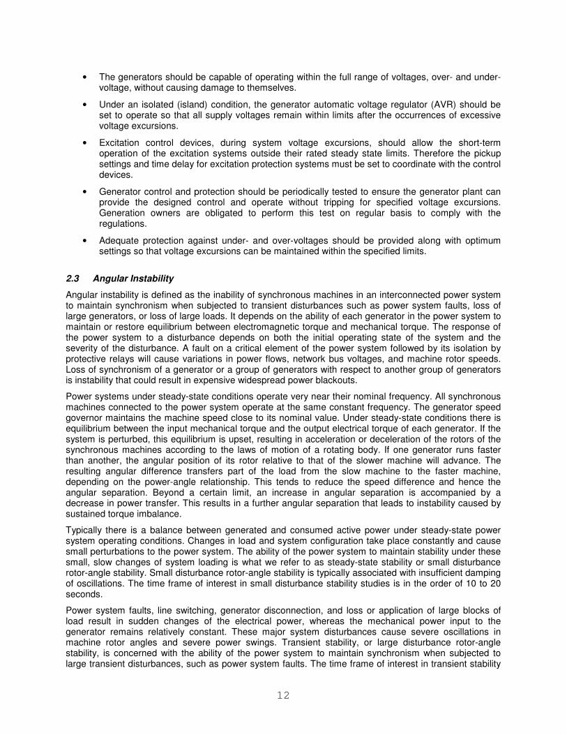
For a simple lossless transmission line connecting a generator to a large equivalent system as shown in Figure 2.5, it is well known that the active power, P, transferred from the generator to the system can be expressed as,
δ= sin•X
E•EP
RS (2.1)
where ES is the generator sending-end source voltage magnitude, ER is the receiving-end source voltage
magnitude, δ is the angle by which the generator voltage ES leads the ER source voltage, and X is the total reactance of the transmission line and the two sources given by Equation 2.2.
X = XS + XL + XR (2.2)
ES
ER
XS
XL
XR
P
Figure 2.5 A Two-Source System
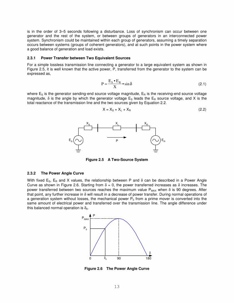
2.3.2 The Power Angle Curve
With fixed ES, ER and X values, the relationship between P and δ can be described in a Power Angle
Curve as shown in Figure 2.6. Starting from δ = 0, the power transferred increases as δ increases. The
power transferred between two sources reaches the maximum value PMAX when δ is 90 degrees. After
that point, any further increase in δ will result in a decrease of power transfer. During normal operations of a generation system without losses, the mechanical power P0 from a prime mover is converted into the same amount of electrical power and transferred over the transmission line. The angle difference under
this balanced normal operation is δ0.
P
δ
0 180
PMAX
90δ0
P0
Figure 2.6 The Power Angle Curve
14
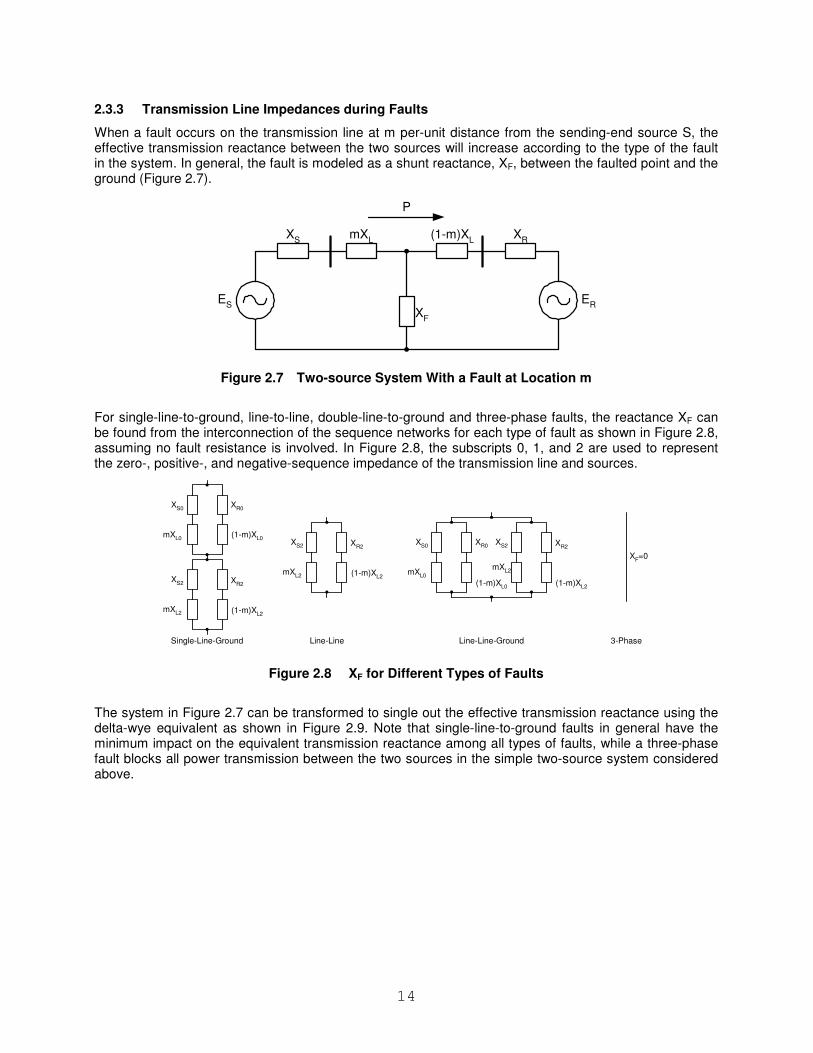
2.3.3 Transmission Line Impedances during Faults
When a fault occurs on the transmission line at m per-unit distance from the sending-end source S, the effective transmission reactance between the two sources will increase according to the type of the fault in the system. In general, the fault is modeled as a shunt reactance, XF, between the faulted point and the ground (Figure 2.7).
ES
ER
XS
mXL
XR
P
(1-m)XL
XF
Figure 2.7 Two-source System With a Fault at Location m
For single-line-to-ground, line-to-line, double-line-to-ground and three-phase faults, the reactance XF can be found from the interconnection of the sequence networks for each type of fault as shown in Figure 2.8, assuming no fault resistance is involved. In Figure 2.8, the subscripts 0, 1, and 2 are used to represent the zero-, positive-, and negative-sequence impedance of the transmission line and sources.
mXL0
XS0
XR0
(1-m)XL0
mXL2
XS2 X
R2
(1-m)XL2
mXL2
XS2 X
R2
(1-m)XL2
mXL0
XS0
XR0
(1-m)XL0
mXL2
XS2 X
R2
(1-m)XL2
Single-Line-Ground Line-Line Line-Line-Ground 3-Phase
XF=0
Figure 2.8 XF for Different Types of Faults
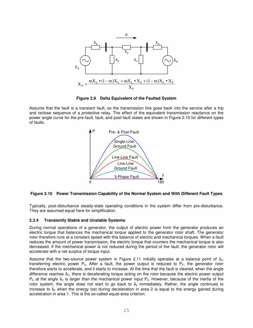
The system in Figure 2.7 can be transformed to single out the effective transmission reactance using the delta-wye equivalent as shown in Figure 2.9. Note that single-line-to-ground faults in general have the minimum impact on the equivalent transmission reactance among all types of faults, while a three-phase fault blocks all power transmission between the two sources in the simple two-source system considered above.
15
ES
ER
XS
XR
P
XX XY
XZ
F
FLFLLLZ X
X•X)m1(X•mXX)m1(•mXX
−++−=
Figure 2.9 Delta Equivalent of the Faulted System
Assume that the fault is a transient fault, so the transmission line goes back into the service after a trip and reclose sequence of a protective relay. The effect of the equivalent transmission reactance on the power angle curve for the pre-fault, fault, and post-fault states are shown in Figure 2.10 for different types of faults.
P
Single-Line-Ground Fault
Line-Line Fault
Line-LineGround Fault
3-Phase Fault δ
0 180
Pre- & Post-Fault
Figure 2.10 Power Transmission Capability of the Normal System and With Different Fault Types
Typically, post-disturbance steady-state operating conditions in the system differ from pre-disturbance. They are assumed equal here for simplification.
2.3.4 Transiently Stable and Unstable Systems
During normal operations of a generator, the output of electric power from the generator produces an electric torque that balances the mechanical torque applied to the generator rotor shaft. The generator rotor therefore runs at a constant speed with this balance of electric and mechanical torques. When a fault reduces the amount of power transmission, the electric torque that counters the mechanical torque is also decreased. If the mechanical power is not reduced during the period of the fault, the generator rotor will accelerate with a net surplus of torque input.
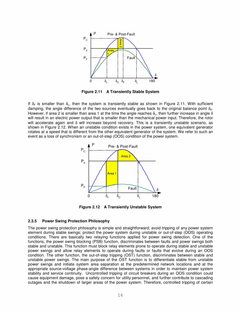
Assume that the two-source power system in Figure 2.11 initially operates at a balance point of δ0, transferring electric power P0. After a fault, the power output is reduced to PF, the generator rotor
therefore starts to accelerate, and δ starts to increase. At the time that the fault is cleared, when the angle
difference reaches δC, there is decelerating torque acting on the rotor because the electric power output
PC at the angle δC is larger than the mechanical power input P0. However, because of the inertia of the
rotor system, the angle does not start to go back to δ0 immediately. Rather, the angle continues to
increase to δF when the energy lost during deceleration in area 2 is equal to the energy gained during acceleration in area 1. This is the so-called equal-area criterion.
16
P
δ
0 180
Pre- & Post-Fault
Fault
P0
δ0
δC
δF
δL
PF
PC
Area
1
Are
a 2
Figure 2.11 A Transiently Stable System
If δF is smaller than δL, then the system is transiently stable as shown in Figure 2.11. With sufficient
damping, the angle difference of the two sources eventually goes back to the original balance point δ0.
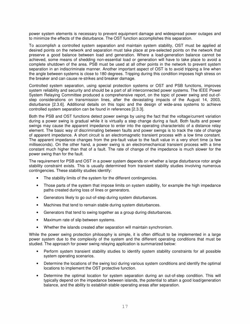
However, if area 2 is smaller than area 1 at the time the angle reaches δL, then further increase in angle δ will result in an electric power output that is smaller than the mechanical power input. Therefore, the rotor
will accelerate again and δ will increase beyond recovery. This is a transiently unstable scenario, as shown in Figure 2.12. When an unstable condition exists in the power system, one equivalent generator rotates at a speed that is different from the other equivalent generator of the system. We refer to such an event as a loss of synchronism or an out-of-step (OOS) condition of the power system.
P
δ
0 180δ0
δC δL
P0
Pre- & Post-Fault
Fault
PC
PF
Area 1
Area 2
Figure 2.12 A Transiently Unstable System
2.3.5 Power Swing Protection Philosophy
The power swing protection philosophy is simple and straightforward; avoid tripping of any power system element during stable swings; protect the power system during unstable or out-of-step (OOS) operating conditions. There are basically two relaying functions applied for power swing detection. One of the functions, the power swing blocking (PSB) function, discriminates between faults and power swings both stable and unstable. This function must block relay elements prone to operate during stable and unstable power swings and allow relay elements to operate during faults or faults that evolve during an OOS condition. The other function, the out-of-step tripping (OST) function, discriminates between stable and unstable power swings. The main purpose of the OST function is to differentiate stable from unstable power swings and initiate system area separation at the predetermined network locations and at the appropriate source-voltage phase-angle difference between systems in order to maintain power system stability and service continuity. Uncontrolled tripping of circuit breakers during an OOS condition could cause equipment damage, pose a safety concern for utility personnel, and further contribute to cascading outages and the shutdown of larger areas of the power system. Therefore, controlled tripping of certain
17
power system elements is necessary to prevent equipment damage and widespread power outages and to minimize the effects of the disturbance. The OST function accomplishes this separation.
To accomplish a controlled system separation and maintain system stability, OST must be applied at desired points on the network and separation must take place at pre-selected points on the network that preserve a good balance between load and generation. Where a load-generation balance cannot be achieved, some means of shedding non-essential load or generation will have to take place to avoid a complete shutdown of the area. PSB must be used at all other points in the network to prevent system separation in an indiscriminate manner. Another important aspect of OST is to avoid tripping a line when the angle between systems is close to 180 degrees. Tripping during this condition imposes high stress on the breaker and can cause re-strikes and breaker damage.
Controlled system separation, using special protection systems or OST and PSB functions, improves system reliability and security and should be a part of all interconnected power systems. The IEEE Power System Relaying Committee produced a comprehensive report, on the topic of power swing and out-of-step considerations on transmission lines, after the devastating impacts of the August 14, 2003, disturbance [2.3.6]. Additional details on this topic and the design of wide-area systems to achieve controlled system separation can be found in references [2.3.3].
Both the PSB and OST functions detect power swings by using the fact that the voltage/current variation during a power swing is gradual while it is virtually a step change during a fault. Both faults and power swings may cause the apparent impedance to enter into the operating characteristic of a distance relay element. The basic way of discriminating between faults and power swings is to track the rate of change of apparent impedance. A short circuit is an electromagnetic transient process with a low time constant. The apparent impedance changes from the pre-fault value to the fault value in a very short time (a few milliseconds). On the other hand, a power swing is an electromechanical transient process with a time constant much higher than that of a fault. The rate of change of the impedance is much slower for the power swing than for the fault.
The requirement for PSB and OST in a power system depends on whether a large disturbance rotor angle stability constraint exists. This is usually determined from transient stability studies involving numerous contingencies. These stability studies identify:
• The stability limits of the system for the different contingencies.
• Those parts of the system that impose limits on system stability, for example the high impedance paths created during loss of lines or generators.
• Generators likely to go out-of-step during system disturbances.
• Machines that tend to remain stable during system disturbances.
• Generators that tend to swing together as a group during disturbances.
• Maximum rate of slip between systems.
• Whether the islands created after separation will maintain synchronism.
While the power swing protection philosophy is simple, it is often difficult to be implemented in a large power system due to the complexity of the system and the different operating conditions that must be studied. The approach for power swing relaying application is summarized below:
• Perform system transient stability studies to identify system stability constraints for all possible system operating scenarios.
• Determine the locations of the swing loci during various system conditions and identify the optimal locations to implement the OST protective function.
• Determine the optimal location for system separation during an out-of-step condition. This will typically depend on the impedance between islands, the potential to attain a good load/generation balance, and the ability to establish stable operating areas after separation.
18
• Establish the maximum rate of slip between systems for OOS timer setting requirements as well as the minimum forward and reverse reach settings required for successful detection of out-of-step conditions.
• Include mathematical models of the power-swing blocking and out-of-step tripping relay operation behavior in the transient stability studies to verify correct application of the out-of-step protection schemes.
2.3.6 References
[2.3.1] P. Kundur, Power System Stability and Control, McGraw-Hill, Inc., New York, 1994.
[2.3.2] D. A. Tziouvaras and D. Hou, “Out-of-Step Protection Fundamentals and Advancements,” Proc. 30th Annual Western Protective Relay Conference, Spokane, WA, October 21–23, 2003.
[2.3.3] A. Guzman, E. O. Schweitzer III, D. A. Tziouvaras, and Ken Martin, “Local and Wide-Area Network Protection Systems Improve Power System Reliability,” Proc. 31st Annual Western Protective Relay Conference, Spokane, WA, October 19-21, 2004.
[2.3.4] F. Ilar, “Innovations in the Detection of Power Swings in Electrical Networks,” Brown Boveri Publication CH-ES 35-30.10E, 1987.
[2.3.5] D. A. Tziouvaras, “Relay Performance During Major System Disturbances,” Proc. 32nd Annual Western Protective Relay Conference, Spokane, WA, October 17–19, 2006.
[2.3.6] “Power Swing and Out-of-Step Considerations on Transmission Lines,” IEEE Power System Relaying Committee, 2005 Report [Online]. Available: http://www.pes-psrc.org.
[2.3.7] D. Tziouvaras, “Analysis of Recent WSCC (1996) Disturbances and Recommended Protection Improvements,” Proc. 52nd Georgia Tech Annual Protective Relay Conference, Atlanta, 1998.
2.4 Small-Signal Instability
Small signal stability is the ability of the power system to restore a state of equilibrium following a small disturbance and is primarily due to generator rotors swinging relative to one another [2.4.1] [2.4.2]. The resultant oscillations are inherent to an interconnected power system, typically occurring in the frequency range of 0.1 to 2 Hz. If the oscillations are not sufficiently damped, they can escalate to the point of reaching control limits or causing protective relays to trip.
The most common type of oscillation encountered is the local plant mode, which typically consists of generators at a station oscillating with respect to the power system. Generators that are “electrically close” to each other can also experience the same relative type of oscillation. The frequencies are generally in the range of 1 to 2 Hz and can occur with the response of the automatic voltage control (AVR) when the generators are supplying high output into a weak system. Although the use of high-response voltage regulators improves transient stability, they add to the problem of local plant mode oscillations by introducing negative damping. To offset the negative damping, power system stabilizers (PSS) have been used to supplement excitation control.
Inter-area oscillations are usually in the frequency range of 0.1 to 1 Hz and are typically associated with heavy power transfers across relatively weak transmission paths. Groups of machines in a particular area can swing relative to other groups of machines in other areas and although the oscillations may be relatively small in each unit, the cumulative oscillation across a tie line can be very significant. As loading increases on the tie line, the system can be pushed to a system operating point across a steady-state stability boundary, and a condition is created where oscillations can be prone to occur.
Once excited, the oscillations can increase in magnitude over the span of many seconds. The oscillations can cause large generator groups to lose synchronism, resulting in uncoordinated disconnection from the system. Even when sustained oscillations do not result in network separation, they may have associated voltage or frequency swings that are unacceptable for system reliability.
During the system oscillations, it is important that relays do not misoperate. Although it is sometimes difficult to foresee the extreme conditions that can occur, load encroachment should be evaluated for
19
system oscillations that may be controllable. If the oscillations approach an unstable condition, then the appropriate out-of-step protection should respond to assure that equipment protection is maintained.
To reduce the likelihood of relay misoperation due to inter-area oscillations, system damping should be sought with PSS systems that are properly tuned. In extreme cases where the PSS may not be adequate, supplementary controls such as HVDC for long-distance transmission or power exchange between asynchronous regions can be provided. Additional damping can also be provided with the installation of static VAr compensators (SVC) for the purpose of dynamic voltage support and thyristor-controlled series capacitors (TCSC).
2.4.1 References
[2.4.1] P. Kundur, J. Paserba, V. Ajjarapu, G. Andersson, A. Bose, C. Canizares, N. Hatziargyriou, D. Hill, A. Stankovic, C. Taylor, T. Van Cutsen and V. Vittal, “Definition and Classification of Power System Stability,” IEEE Transactions on Power Systems, Vol. 19, No. 2, May 2004
[2.4.2] P. Kundur, K. Morrison, J. Paserba, J. Sanchez-Gasca, E. Larsen, Y. Mansour, V. Vittal, C. Taylor, W. Price, J.F. Hauer, W. Mittelstadt, M.K. Donnelly, W.H. Litzenberger, “The Electric Power Engineering Handbook”
2.5 High Equipment Loadings and High Power Transfers
Stressed conditions often occur near or at system peak load. The high system loads perpetuate high equipment loadings throughout the electrical system. This loading is usually at a poor power factor due to the types of loads that are being served and to high reactive losses through lines and transformers. The high current flow through equipment causes higher temperatures from the resistive losses. The higher equipment temperatures result in several negative affects such as conductor sag and loss of insulation. The following issues are important to consider:
• The electrical system is designed to meet the voltages and frequency requirements without overloading any element when operating in steady state.
• Outages in the system are frequent events and when they occur the power flows are altered and re-distributed. Generally, power systems are designed to withstand one contingency only, called the “n-1” condition.
• Planned and maintenance outages should not cause an overload that causes an excessive loss of life to system elements as they are carefully managed. However, the forced outage of one or more elements in the system may be the beginning of a major system incident.
• The unexpected loss of any system element during low load conditions may result in new power flows but it should not violate either the stability or the thermal limits of any other remaining element.
• During normal or heavy loads the sudden loss of any transmission element will result in higher load flows and could also affect both the transient stability and the voltage stability margins.
• The higher load flows following a forced outage may result in system element loadings above the thermal limits causing accelerated aging. Transformers, line conductors and cables are very susceptible to this.
Furthermore, the redistribution of the load flows also translates into higher power angles (the angle between the voltages at each line terminal), affecting auto-recloser operation.
Higher load flows cause the sag of conductors of overhead lines to increase, reducing the minimum clearance to ground. This is a dire situation during summer due to high ambient temperatures; the conductor can touch a tree or other object causing a new fault that requires clearing and auto-reclosing which may not be successful. This situation can also be an unsafe condition.
20
2.5.1 Cold Load Pickup
After distribution loads such as furnaces, refrigerators, water heaters and air conditioners have been out of service for a long time, there will be a loss of diversity in the loads when service is restored. The total current inrush may be several times the normal peak load current and will be sustained for several seconds before decaying to a normal load level. This inrush current during restoration of load is called cold load pickup and can cause over-current relay operation.
2.6 Frequency Excursions
Frequency variations occur due to imbalance between generated and consumed power. This situation may be caused by:
• Variations in load demand or power generated: an overload of the system caused by excessive load and insufficient generation results in a decline in system frequency while disconnection of loads will increase the frequency.
• Power system faults or line switching: a redistribution of load flow by re-routing produces changes in power transfer between different portions of the system or between interconnected systems which result in frequency fluctuations until a new equilibrium is established between generation and load.
The magnitude and duration of frequency variations depend on the level of imbalance between generated and consumed power and the response to this imbalance by the generators (inertia of the rotating machines, and generation control systems). If the frequency excursion is caused by a fault, the duration of the frequency variation is a direct function of how long it takes for the fault to be cleared.
Frequency variations can endanger system stability and may cause damage to generators and, in particular, damage of steam turbines. Frequency below nominal value produces, at nominal voltage, over-excitation of generators with severe heating as a result. In addition, when reducing the turbine’s rotating speed the frequency may approach the resonant frequency of the rotor blades and cause serious blade fatigue. The effect is cumulative so that the problem is exacerbated every time the turbine is subjected to an under-frequency situation. It is also important to note that low frequency could cause the power plant auxiliaries systems to trip out by reduced pump outputs and fan speeds with the result of having to take the generator station off line.
Generators are provided with regulation systems to correct any load-generation imbalance that may occur. All generators driven by turbines include a turbine governor (primary regulation) which changes the flow (of steam, water or fuel) that enters the turbine when the speed is no longer in synchronism with the system. The control slows down the frequency excursions by correcting imbalances between generation and demand, in case they are not excessive. However, while the primary frequency regulation may stop the excursion, it does not return the frequency to its nominal value. To achieve the latter goal, there is another control (Automatic Generator Control), which operates on a global level and is active over large areas of generation but with a longer reaction time.
When there is sufficient spinning reserve, a sudden increase in load demand can be compensated for via the regulating methods for generators previously mentioned. However, if the available generation has reached its maximum, the frequency will start to decline. In this case, it is necessary to initiate a selective disconnection of loads (load shedding) with the object of restoring the frequency to normal levels. Carrying out the load shedding in the required time frame is critical as otherwise a continuing decline in frequency may trigger the generator under-frequency relays and make the problem worse. In regions with insufficient generation, interconnection of grids is of great importance as it allows the use of spinning reserves in a neighboring system.
If the generator-control systems and system control load shedding operate as intended, the frequency can be maintained within the established margins. However, the reaction time of these systems may not be sufficiently short to handle large generation/load imbalances caused by the loss of large blocks of generation or the tripping of an important tie line, with severe frequency variations as a result.
21
Power systems lacking strong interconnections and without sufficient spinning reserves are likely to suffer frequency excursions. In addition, frequent defects or failures of the regulating control systems may cause these systems often to exhibit frequency variations far above admissible levels.
Frequency variations have a major impact on protective relay response, especially for distance relays. Frequency variations occur during stressed system conditions and it is critical that protective relays remain fully operational, as the power system is very vulnerable to further disturbances at this time. Both loss of security (undesired tripping) and loss of dependability (no trip) could aggravate the situation. An undesired trip during a frequency excursion is counterproductive to the operational strategy to correct the problem. On the other hand, excessive restraint resulting in a lack of tripping for a fault caused by the excursion will further aggravate the situation.
2.7 High System Unbalance
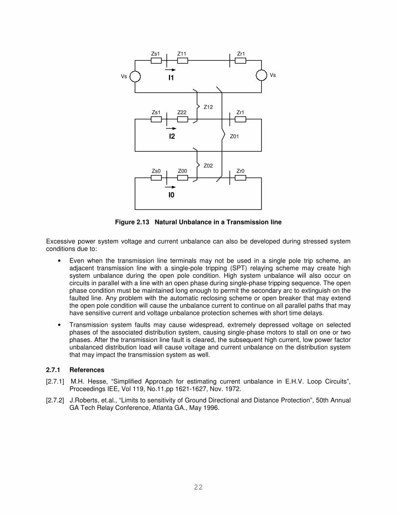
Power system voltage and current unbalance can adversely affect power system apparatus and circuit protection devices. Current unbalance is due to asymmetry of the transmission line tower configurations and can be evaluated [2.7.1]. Heavily loaded untransposed transmission lines can be a cause of significant system current unbalance.
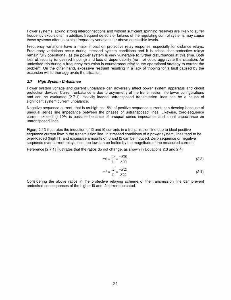
Negative-sequence current, that is as high as 15% of positive-sequence current, can develop because of unequal series line impedance between the phases of untransposed lines. Likewise, zero-sequence current exceeding 10% is possible because of unequal series impedance and shunt capacitance on untransposed lines. Figure 2.13 illustrates the induction of I2 and I0 currents in a transmission line due to ideal positive sequence current flow in the transmission line. In stressed conditions of a power system, lines tend to be over-loaded (high I1) and excessive amounts of I0 and I2 can be induced. Zero sequence or negative sequence over current relays if set too low can be fooled by the magnitude of the measured currents.
Reference [2.7.1] illustrates that the ratios do not change, as shown in Equations 2.3 and 2.4:
00
01
I1
I0 m0
Z
Z−== (2.3)
22
21
I1
I2 m2
Z
Z−== (2.4)
Considering the above ratios in the protective relaying scheme of the transmission line can prevent undesired consequences of the higher I0 and I2 currents created.
22
Vs I1
Zs1
Zs1
Zs0
Z11
Z22
Z00
Zr1
Zr1
Zr0
Vs
+ +
+ +
+ +
I2
I0
Z12
Z02
Z01
Figure 2.13 Natural Unbalance in a Transmission line
Excessive power system voltage and current unbalance can also be developed during stressed system conditions due to:
• Even when the transmission line terminals may not be used in a single pole trip scheme, an adjacent transmission line with a single-pole tripping (SPT) relaying scheme may create high system unbalance during the open pole condition. High system unbalance will also occur on circuits in parallel with a line with an open phase during single-phase tripping sequence. The open phase condition must be maintained long enough to permit the secondary arc to extinguish on the faulted line. Any problem with the automatic reclosing scheme or open breaker that may extend the open pole condition will cause the unbalance current to continue on all parallel paths that may have sensitive current and voltage unbalance protection schemes with short time delays.
• Transmission system faults may cause widespread, extremely depressed voltage on selected phases of the associated distribution system, causing single-phase motors to stall on one or two phases. After the transmission line fault is cleared, the subsequent high current, low power factor unbalanced distribution load will cause voltage and current unbalance on the distribution system that may impact the transmission system as well.
2.7.1 References
[2.7.1] M.H. Hesse, “Simplified Approach for estimating current unbalance in E.H.V. Loop Circuits”, Proceedings IEE, Vol 119, No.11,pp 1621-1627, Nov. 1972.
[2.7.2] J.Roberts, et.al., “Limits to sensitivity of Ground Directional and Distance Protection”, 50th Annual GA Tech Relay Conference, Atlanta GA., May 1996.
23
3 Protection Related Behavior Under Stressed Conditions
This section will address the behavior of protection functions under stressed operating conditions that are defined in Section 2. The following protection schemes will be analyzed:
• Transmission line protection, including, series compensated lines, parallel lines, tapped lines, and untransposed lines
• Transformer protection
• Generator protection
• Bus protection
• Shunt reactor/capacitor protection
• Feeder protection
• Motor protection
As off-nominal frequency affects the calculation of the phasors used in most of the microprocessor relays, this issue will be addressed first.
3.1 Impact of Off-nominal Frequencies on Phasors
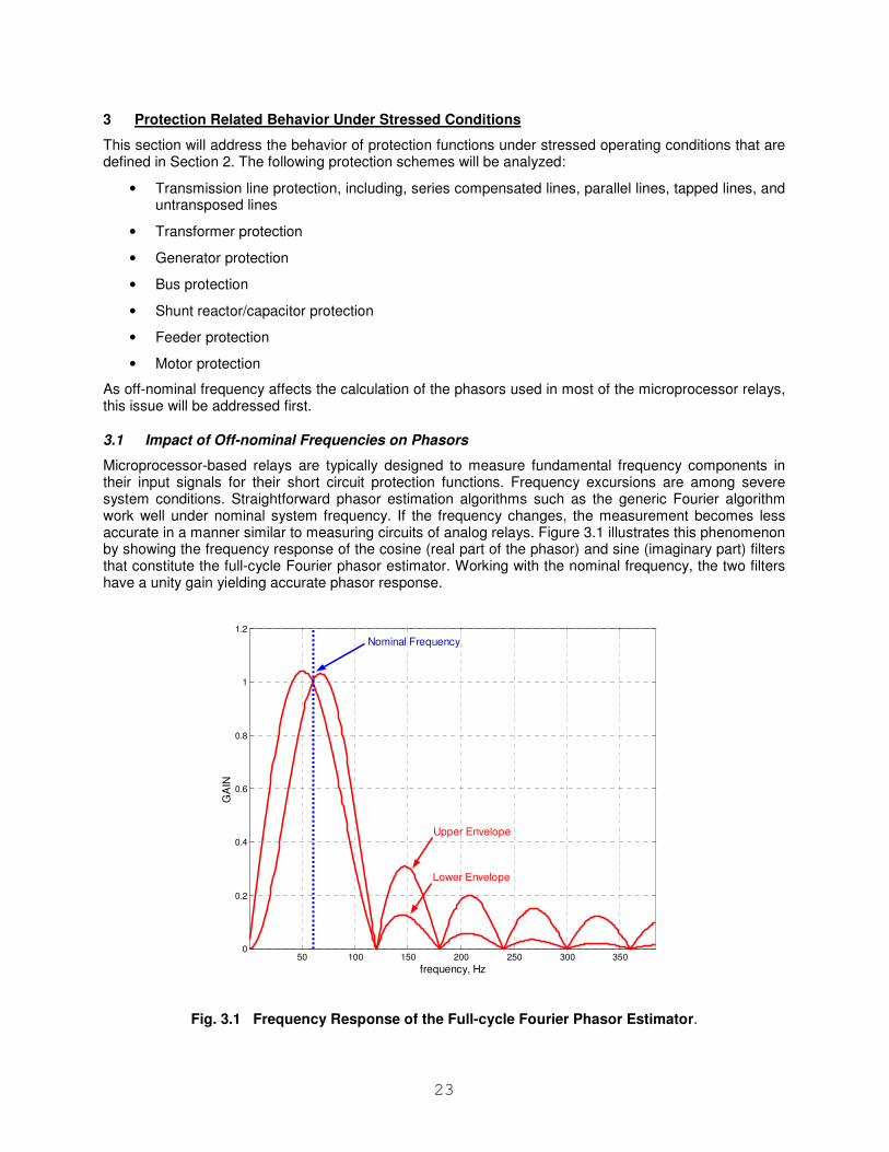
Microprocessor-based relays are typically designed to measure fundamental frequency components in their input signals for their short circuit protection functions. Frequency excursions are among severe system conditions. Straightforward phasor estimation algorithms such as the generic Fourier algorithm work well under nominal system frequency. If the frequency changes, the measurement becomes less accurate in a manner similar to measuring circuits of analog relays. Figure 3.1 illustrates this phenomenon by showing the frequency response of the cosine (real part of the phasor) and sine (imaginary part) filters that constitute the full-cycle Fourier phasor estimator. Working with the nominal frequency, the two filters have a unity gain yielding accurate phasor response.
50 100 150 200 250 300 3500
0.2
0.4
0.6
0.8
1
1.2
GA
IN
frequency, Hz
Nominal Frequency
Upper Envelope
Lower Envelope
Fig. 3.1 Frequency Response of the Full-cycle Fourier Phasor Estimator.
24
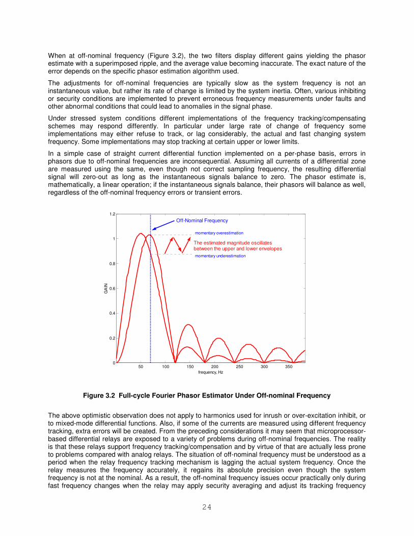
When at off-nominal frequency (Figure 3.2), the two filters display different gains yielding the phasor estimate with a superimposed ripple, and the average value becoming inaccurate. The exact nature of the error depends on the specific phasor estimation algorithm used.
The adjustments for off-nominal frequencies are typically slow as the system frequency is not an instantaneous value, but rather its rate of change is limited by the system inertia. Often, various inhibiting or security conditions are implemented to prevent erroneous frequency measurements under faults and other abnormal conditions that could lead to anomalies in the signal phase.
Under stressed system conditions different implementations of the frequency tracking/compensating schemes may respond differently. In particular under large rate of change of frequency some implementations may either refuse to track, or lag considerably, the actual and fast changing system frequency. Some implementations may stop tracking at certain upper or lower limits.
In a simple case of straight current differential function implemented on a per-phase basis, errors in phasors due to off-nominal frequencies are inconsequential. Assuming all currents of a differential zone are measured using the same, even though not correct sampling frequency, the resulting differential signal will zero-out as long as the instantaneous signals balance to zero. The phasor estimate is, mathematically, a linear operation; if the instantaneous signals balance, their phasors will balance as well, regardless of the off-nominal frequency errors or transient errors.
50 100 150 200 250 300 3500
0.2
0.4
0.6
0.8
1
1.2
GA
IN
frequency, Hz
Off-Nominal Frequency
The estimated magnitude oscillates between the upper and lower envelopes
momentary overestimation
momentary underestimation
Figure 3.2 Full-cycle Fourier Phasor Estimator Under Off-nominal Frequency
The above optimistic observation does not apply to harmonics used for inrush or over-excitation inhibit, or to mixed-mode differential functions. Also, if some of the currents are measured using different frequency tracking, extra errors will be created. From the preceding considerations it may seem that microprocessor-based differential relays are exposed to a variety of problems during off-nominal frequencies. The reality is that these relays support frequency tracking/compensation and by virtue of that are actually less prone to problems compared with analog relays. The situation of off-nominal frequency must be understood as a period when the relay frequency tracking mechanism is lagging the actual system frequency. Once the relay measures the frequency accurately, it regains its absolute precision even though the system frequency is not at the nominal. As a result, the off-nominal frequency issues occur practically only during fast frequency changes when the relay may apply security averaging and adjust its tracking frequency
25
intentionally slower compared with the changes in the power system. For example some of the islands during the 2003 blackout showed frequency changes in excess of 30Hz/sec for duration of 100-200ms when coasting down before a total disintegration of generators and loads. Some relays would not allow such excessive changes in their tracking frequency, which led to a temporary lag between the system and tracking frequencies. Normally, even during severe system events, the frequency would change well within the design limits of the relay frequency tracking/compensation mechanism allowing it to catch up to the system frequency and maintain correct measurements. It is only the case of excessive frequency changes, inadvertently disabled frequency tracking, or absence of the signal selected for tracking that may lead to the problems described here.
In contrast, analog relays would respond permanently in a deteriorated, difficult to predict, way under off-nominal frequencies as dictated by their design driven by electro-mechanical or solid-state circuitries.
3.2 Transmission Line Protection
The North American power system consists of thousands of high voltage transmission lines transmitting electrical power between generators and load centers. They represent the foundation of the power system. The majority of transmission line construction is of overhead type and therefore, is easily susceptible to various transient and permanent faults. These faults can lead to damage of the line itself and can cause power system instability. It is of utmost importance that protective relay systems are capable of clearing all faults within the designed operating time, and have a high degree of dependability and security.
Protective devices operate when a condition within the respective device set points is detected. These conditions may be caused by faults or other situations that may place the power system within the operating range of the device. Therefore, a protective relay may operate for conditions such as:
• Fault outside of its intended application or zone
• Power swing/Angular Instability
• Load encroachment
• Frequency deviation
• Voltage instability
• Combination of the above
The behavior of transmission protective relays during several recent major blackouts combined with the significant pressure to increase the transfer limits to serve the increasing demand are the key reasons to study the protection performance during stressed conditions.
3.2.1 Effect of Angular Instability on Transmission Line Protection
Angular instability or out-of-step (OOS) condition, in many cases, is prevented by the action of protective devices. The goal of these protective devices is to prevent damage to power system components, e.g. due to fault currents, over-voltage, or over-speed. Protective devices detect the existence of abnormal system conditions by monitoring appropriate system quantities and disconnecting appropriate transmission lines, generators, and loads. In many cases, the change in the system’s topology restores the stability of the power system, because the faulted component threatening the stability is removed from the system.
Depending on the severity of the disturbance and the actions of protective relays and power system controls, the system may remain stable and return to a new equilibrium state experiencing what is referred to as a stable power swing. Severe system disturbances, on the other hand, could cause large separation of generator rotor angles, large swings of power flows, large fluctuations of voltages and currents, and eventual loss of synchronism between groups of generators or between neighboring utility systems.
Large power swings, stable or unstable, can cause unwanted relay operations at different network locations, which can aggravate further the power system disturbance and possibly lead to cascading

26
outages and power blackouts. Protective relays prone to respond to an unstable swing and cause unwanted tripping include: over-current, under-voltage, distance, directional comparison relaying schemes, and loss-of-excitation. These types of relay elements could be blocked from operating to prevent equipment damage, and the shutdown of major portions of the power system. Out-of-step blocking protection is beneficial to avoid such unwanted tripping. However, it is necessary to protect the power system during unstable conditions, and some protection schemes are designed to isolate unstable generators or groups of generators from each other, in order to maintain stability within each group of generators. Out-of-step tripping schemes are designed and used for this purpose. Both out-of-step blocking and out-of-step tripping functions are available in most microprocessor distance relays.
Distance relay elements set to be blocked during an OOS condition could cause unnecessary tripping of transmission lines after the first slip cycle if the OOS blocking function fails to maintain blocking of the distance elements during subsequent slip cycles [2.3.6]. Fine-tuning of the OOS blocking concentric impedance elements and power swing blocking timer settings could prevent a line trip. However, setting conventional OOS blocking and OOS tripping functions can be very difficult on long overloaded lines, depending on source strengths, and requires extensive stability studies.
3.2.2 Automatic Reclosing and Synchro-check
Appropriate automatic reclosing is vital to system stability to restore as much of the system as practical following transient fault events and to restore power transfer stability margins by increasing the net power transfer capability of the transmission system. High-speed automatic reclosing (generally 1 second or less) is capable of stabilizing a system that otherwise would go unstable. Although synchro-check relays should be used, high-speed reclosing occurs quicker than synchro-check verification can occur (due to setting criteria and margins). However, with high-speed reclosing, a system that is stable prior to the line opening will still be closely enough synchronized to allow reclosing. Obviously, high speed reclosing should only be used on systems that provide instantaneous tripping for 100% of the line, or there is a high probability that the reclose will not be successful.
For time-delayed reclosing or operator initiated reclosing, it is imperative that synchro-check verification be utilized to ensure that two systems out of synchronization are not tied together. While time delay reclosing is not effective in stabilizing a system that is going unstable, its use can provide additional stability margin by restoring the maximum power transfer limit.
Since it is not possible to predetermine which faults are transient vs. permanent and the effects of closing into some faults can be the trigger to drive systems unstable, in some instances it is prudent to block reclosing for certain fault events. For instance since three phase faults, especially close-in three phase faults are severe from a stability standpoint, reclosing for the terminal closest to the fault can be blocked . If the reclose is successful from the other terminal, then the terminal can be reclosed into a hot line without risk.
3.2.3 Line Distance Protection
Distance relays have been successfully used for many years as the most common type of protection of transmission lines. The development of electromechanical and solid state relays with mho or quadrilateral characteristics coupled with simple methods to derive at relay set points have been important in the wide acceptance of this type of protection at different voltage levels all over the world.
3.2.3.1 Load encroachment
The measuring elements of a distance relay should consider that the relay provides sufficient resistive reach, to ensure correct operation when a fault is inside of the designed or intended zone of protection. At the same time, the characteristic should have a shape narrow enough so that dynamic line loading impedance does not enter inside the characteristics such that will result in undesired tripping of the protected line at the time when it is needed the most. The set points should therefore be derived such that the relay does not under or over-reach of the desired characteristics.
The apparent impedance seen by the relays under very heavy loads may lead to relay tripping. This is especially true in the case of long transmission lines or Zone 3 elements that have to provide backup
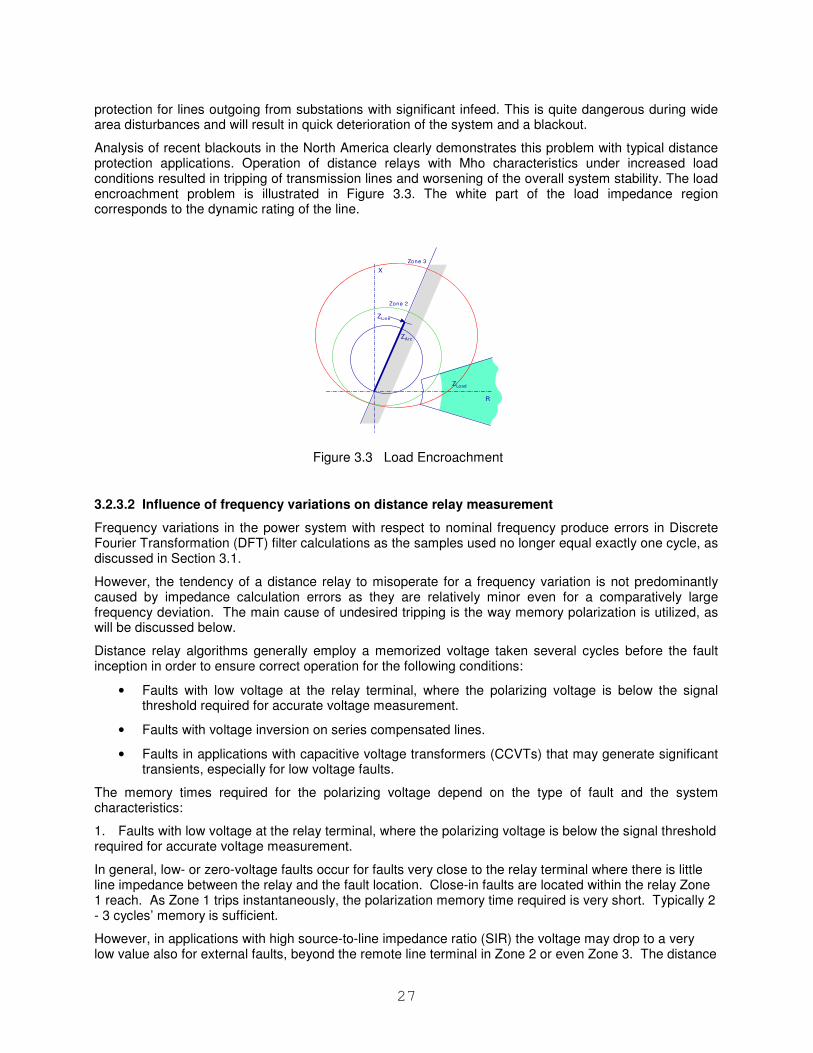
27
protection for lines outgoing from substations with significant infeed. This is quite dangerous during wide area disturbances and will result in quick deterioration of the system and a blackout.
Analysis of recent blackouts in the North America clearly demonstrates this problem with typical distance protection applications. Operation of distance relays with Mho characteristics under increased load conditions resulted in tripping of transmission lines and worsening of the overall system stability. The load encroachment problem is illustrated in Figure 3.3. The white part of the load impedance region corresponds to the dynamic rating of the line.
R
X
ZLoad
ZArc
ZLine
Zone 2
Zone 3
Figure 3.3 Load Encroachment
3.2.3.2 Influence of frequency variations on distance relay measurement
Frequency variations in the power system with respect to nominal frequency produce errors in Discrete Fourier Transformation (DFT) filter calculations as the samples used no longer equal exactly one cycle, as discussed in Section 3.1.
However, the tendency of a distance relay to misoperate for a frequency variation is not predominantly caused by impedance calculation errors as they are relatively minor even for a comparatively large frequency deviation. The main cause of undesired tripping is the way memory polarization is utilized, as will be discussed below.
Distance relay algorithms generally employ a memorized voltage taken several cycles before the fault inception in order to ensure correct operation for the following conditions:
• Faults with low voltage at the relay terminal, where the polarizing voltage is below the signal threshold required for accurate voltage measurement.
• Faults with voltage inversion on series compensated lines.
• Faults in applications with capacitive voltage transformers (CCVTs) that may generate significant transients, especially for low voltage faults.
The memory times required for the polarizing voltage depend on the type of fault and the system characteristics:
1. Faults with low voltage at the relay terminal, where the polarizing voltage is below the signal threshold required for accurate voltage measurement.
In general, low- or zero-voltage faults occur for faults very close to the relay terminal where there is little line impedance between the relay and the fault location. Close-in faults are located within the relay Zone 1 reach. As Zone 1 trips instantaneously, the polarization memory time required is very short. Typically 2 - 3 cycles’ memory is sufficient.
However, in applications with high source-to-line impedance ratio (SIR) the voltage may drop to a very low value also for external faults, beyond the remote line terminal in Zone 2 or even Zone 3. The distance
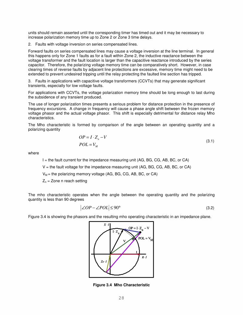
28
units should remain asserted until the corresponding timer has timed out and it may be necessary to increase polarization memory time up to Zone 2 or Zone 3 time delays.
2. Faults with voltage inversion on series compensated lines.
Forward faults on series compensated lines may cause a voltage inversion at the line terminal. In general this happens only for Zone 1 faults as for a fault within Zone 2, the inductive reactance between the voltage transformer and the fault location is larger than the capacitive reactance introduced by the series capacitor. Therefore, the polarizing voltage memory time can be comparatively short. However, in case clearing times of reverse faults by adjacent line protections are excessive, memory time might need to be extended to prevent undesired tripping until the relay protecting the faulted line section has tripped.
3. Faults in applications with capacitive voltage transformers (CCVTs) that may generate significant transients, especially for low voltage faults.
For applications with CCVTs, the voltage polarization memory time should be long enough to last during the subsidence of any transient produced.
The use of longer polarization times presents a serious problem for distance protection in the presence of frequency excursions. A change in frequency will cause a phase angle shift between the frozen memory voltage phasor and the actual voltage phasor. This shift is especially detrimental for distance relay Mho characteristics.
The Mho characteristic is formed by comparison of the angle between an operating quantity and a polarizing quantity
n
M
OP I Z V
POL V
= ⋅ −
= (3.1)
where
I = the fault current for the impedance measuring unit (AG, BG, CG, AB, BC, or CA)
V = the fault voltage for the impedance measuring unit (AG, BG, CG, AB, BC, or CA)
VM = the polarizing memory voltage (AG, BG, CG, AB, BC, or CA)
Zn = Zone n reach setting
The mho characteristic operates when the angle between the operating quantity and the polarizing quantity is less than 90 degrees
90OP POL∠ − ∠ ≤ ° (3.2)
Figure 3.4 is showing the phasors and the resulting mho operating characteristic in an impedance plane.
V
nI Z⋅
I
nOP I Z V= ⋅ −
MPOL V=
IZs ⋅
IR ⋅
IX ⋅
V
nI Z⋅
I
nOP I Z V= ⋅ −
MPOL V=
IZs ⋅
IR ⋅
IX ⋅
Figure 3.4 Mho Characteristic
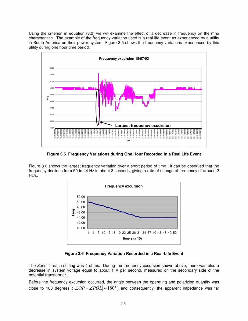
29
Using the criterion in equation (3.2) we will examine the effect of a decrease in frequency on the mho characteristic. The example of the frequency variation used is a real-life event as experienced by a utility in South America on their power system. Figure 3.5 shows the frequency variations experienced by this utility during one hour time period.
Frequency excursion 18/07/03
44,00
45,00
46,00
47,00
48,00
49,00
50,00
51,00
52,00
53,00
19
:26
:00
:00
8
19
:27
:10
:04
4
19
:28
:20
:08
0
19
:29
:31
:01
6
19
:30
:41
:06
8
19
:31
:52
:00
4
19
:33
:02
:04
6
19
:34
:12
:08
2
19
:35
:23
:01
7
19
:36
:33
:07
0
19
:37
:44
:00
6
19
:38
:54
:04
2
19
:40
:04
:07
8
19
:41
:15
:01
4
19
:42
:25
:05
0
19
:43
:35
:09
1
19
:44
:46
:02
7
19
:45
:56
:06
3
19
:47
:06
:09
9
19
:48
:17
:03
5
19
:49
:27
:07
1
19
:50
:38
:00
7
19
:51
:48
:06
5
19
:52
:59
:00
1
19
:54
:09
:03
1
19
:55
:19
:07
3
19
:56
:30
:01
4
19
:57
:40
:05
0
19
:58
:50
:08
6
20
:00
:01
:02
2
20
:01
:11
:05
8
20
:02
:22
:01
6
20
:03
:32
:05
2
20
:04
:42
:08
8
20
:05
:53
:02
4
20
:07
:03
:06
5
20
:08
:14
:00
1
20
:09
:24
:03
7
20
:10
:34
:07
3
20
:11
:45
:00
9
20
:12
:55
:04
5
20
:14
:05
:08
1
20
:15
:16
:03
3
20
:16
:26
:07
5
20
:17
:37
:01
1
20
:18
:47
:04
7
20
:19
:57
:08
3
20
:21
:08
:01
9
20
:22
:18
:07
1
Time
Fre
q
Figure 3.5 Frequency Variations during One Hour Recorded in a Real Life Event
Figure 3.6 shows the largest frequency variation over a short period of time. It can be observed that the frequency declines from 50 to 44 Hz in about 3 seconds, giving a rate-of-change of frequency of around 2 Hz/s.
Frequency excursion
40.00
42.00
44.00
46.00
48.00
50.00
52.00
1 4 7 10 13 16 19 22 25 28 31 34 37 40 43 46 49 52
time s (x 10)
Fre
q
Figure 3.6 Frequency Variation Recorded in a Real-Life Event
The Zone 1 reach setting was 4 ohms. During the frequency excursion shown above, there was also a decrease in system voltage equal to about 1 V per second, measured on the secondary side of the potential transformer.
Before the frequency excursion occurred, the angle between the operating and polarizing quantity was
close to 180 degrees ( 180OP POL∠ − ∠ ≈ ° ) and consequently, the apparent impedance was far
Largest frequency excursion
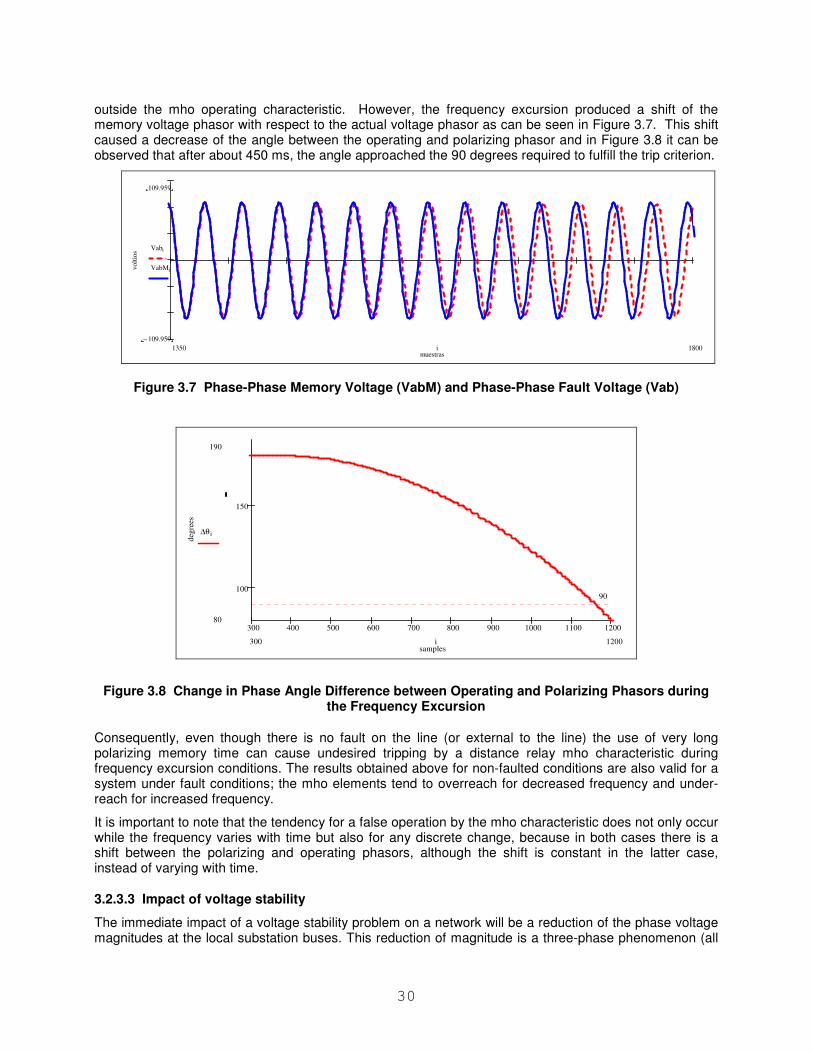
30
outside the mho operating characteristic. However, the frequency excursion produced a shift of the memory voltage phasor with respect to the actual voltage phasor as can be seen in Figure 3.7. This shift caused a decrease of the angle between the operating and polarizing phasor and in Figure 3.8 it can be observed that after about 450 ms, the angle approached the 90 degrees required to fulfill the trip criterion.
muestras
volt
ios
109.959
109.959−
Vabi
VabMi
18001350 i
Figure 3.7 Phase-Phase Memory Voltage (VabM) and Phase-Phase Fault Voltage (Vab)
300 400 500 600 700 800 900 1000 1100 1200
100
150
samples
deg
rees
190
80
90
∆θ i
1200300 i
Figure 3.8 Change in Phase Angle Difference between Operating and Polarizing Phasors during the Frequency Excursion
Consequently, even though there is no fault on the line (or external to the line) the use of very long polarizing memory time can cause undesired tripping by a distance relay mho characteristic during frequency excursion conditions. The results obtained above for non-faulted conditions are also valid for a system under fault conditions; the mho elements tend to overreach for decreased frequency and under-reach for increased frequency.
It is important to note that the tendency for a false operation by the mho characteristic does not only occur while the frequency varies with time but also for any discrete change, because in both cases there is a shift between the polarizing and operating phasors, although the shift is constant in the latter case, instead of varying with time.
3.2.3.3 Impact of voltage stability
The immediate impact of a voltage stability problem on a network will be a reduction of the phase voltage magnitudes at the local substation buses. This reduction of magnitude is a three-phase phenomenon (all
31
three phases should be equally affected) and the rate-of-change of the voltage should normally be a slow value (corresponding to voltage reduction occurring in time frames of from a few seconds to a few hours).
Abrupt changes occurring in a few cycles are to be considered as exceptional but should not be discounted. A distance element basically computes the ratio of a voltage over a current to measure an impedance. When the ratio gets low enough, due to the reduction in the voltage magnitude, to enter the applied impedance characteristic, the relay issues a tripping signal.
When a voltage stability problem occurs on a network with the expected reduction of the voltage magnitudes, the possibility exists that the impedance measured by the distance relays could infringe into the element characteristic and the voltage instability could then be the cause for the tripping of the line. This situation is the same as the one occurring during an out-of-step when the distance element will trip not because of a phase fault but because the computed impedance infringing into the element characteristic.
3.2.4 Line Differential Protection
Current Differential or Current Comparison relays operate by comparing the currents at the two (or three) line terminals. Current Differential relay design may be electromechanical (pilot wire), solid state or digital.
Comparing current flowing into a line to the current flowing out of the same line allows for a simple protection scheme with high sensitivity and high speed simultaneous tripping of both line terminals. At the same time, the differential scheme is unaffected by external effects such as faults, load and power swings.
The differential current can be measured using different methods:
• Magnitude comparison
• Phase comparison
• Phasor comparison (magnitude and angle)
• Charge comparison
• Combinations of the above
Regardless of the method used, all line differential relays operate on a difference in current into the line compared to the current out of the line. The relay design might be affected by non-fundamental phenomena such as harmonics or frequency deviations depending on the filtering technique and comparison method used. Current differential relays are generally not greatly affected by other stressed system conditions due to the fact that non-fundamental quantities are identical in all line ends and a comparison of the currents will still provide a valid result and correctly determine if there is an external or internal fault present. Nevertheless there are several aspects of the operation and design of differential relays that need to be considered during stressed system conditions.
3.2.4.1 Frequency tracking in line current differential schemes
Microprocessor-based line current differential schemes sample their input signals at the individual terminals with a dual goal. Firstly, to take the measurements at the same, or at precisely known, points in time, so that the digital measurements taken tens or hundreds of miles apart can be used in the same differential equations. Relays with frequency tracking capability, can also account for the actual system frequency. In other words the relays must stay in synchronism with each other, or with the arbitrary master, to facilitate the differential protection principle in the first place, and should stay in synchronism with the power system for accurate phasor measurements.
With respect to the latter, a line current differential system may track the system frequency in either a symmetrical or asymmetrical manner. A symmetrical scheme uses an equivalent average frequency between all line terminals to adjust the sampling process or compensate the raw phasors. An asymmetrical scheme uses only local frequency measurement at a given terminal to adjust phasors taken at this terminal.
32
The symmetrical schemes are immune to off-nominal frequency problems. Even if the tracking/compensating frequency is not correct, its value is identical at all terminals of the line. Because all relays use the same tracking frequency, potential errors cancel as explained in the previous section, and no spurious differential signal is created as a result of off-nominal frequencies.
This is not the case for asymmetrical schemes. If each terminal uses frequency derived locally, the tracking frequencies may differ considerably between the terminals under severe system events. This is not necessarily because the actual system frequencies differ significantly, but because individual relays of the differential scheme may respond differently to their local input signals. When the individual currents of the scheme are measured assuming different frequencies, spurious differential signals can be created jeopardizing security of the line current differential scheme.
Operating in either the phase-segregated or mixed-mode is another important factor regarding off-nominal frequencies. Phase-segregated differential schemes are immune to errors caused by off-nominal frequencies as explained above. The mixed-current schemes may be exposed to some problems as follows.
The mixed-mode schemes are typically based on zero-sequence currents to cover ground faults, and negative-sequence currents for phase faults. If the zero-sequence current is balanced under off-nominal frequencies between the line terminals, it will remain balanced as measured via phasors as well. However, spurious negative-sequence currents will occur in response to off-nominal frequencies. This may jeopardize the security of the line differential scheme; unless the problem is recognized by the relay designers and extra measures are applied to counterbalance the phenomenon. Such measures in turn, often proprietary, might have unforeseen side effects on both security and dependability.
There are current differential schemes that utilize raw current samples as opposed to filtered phasors (for instance the charge comparison principle) and these relays are not sensitive to off-nominal frequency and do not need frequency tracking algorithms.
3.2.4.2 Asymmetric channel delays
The risk of asymmetric channel delays affecting current differential relays has to be considered for system wide disturbances. In case communications are made over a network, outage of power supply to some nodes in the network could cause switching of the network path in a way that results in different transmit and receive channel delays. Some current differential relay designs are prone to misoperate for this type of condition.
The important issue during stressed system conditions is increased load currents surpassing trip thresholds caused by asymmetric channel delays.
3.2.5 Tripping of Ground Over-current Element Caused by Dynamic Line Loading
The effect on phase over-current protection relays during wide area disturbances is not expected to be significant. Since phase over-current protection has limited use at the transmission or bulk level of the power system, high balanced current should not result in protection operation. However, in real life the system is quite often imbalanced. Un-transposed transmission lines may have a difference in the impedance of the individual phases in the range of up to 10%. As a result, the high current during dynamic loading or system oscillations may create sufficient zero sequence current that will lead to the operation of a backup ground over-current element of a multifunctional protection relay. A ground pilot element could also operate to trip for example in a DCB scheme if a hole occurs in the blocking signal and sufficient unbalanced current exists.
When studying the effect of high line loading on protective relays, proper system models are required to correctly identify their impact. Since most short circuit analysis programs or protection coordination software are based on a power system model with balanced phase impedances, they do not take into consideration the effect of the un-transposed line on the ground over-current protection coordination.
Reference [3.2.1] discusses the natural unbalance in transmission networks and illustrates the natural relationship of induced zero sequence (I0) and negative sequence (I2) currents due to load flow in the
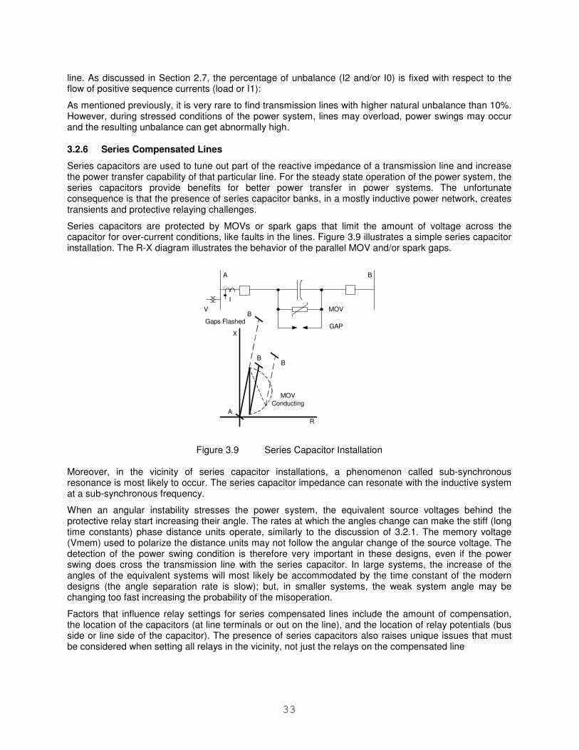
33
line. As discussed in Section 2.7, the percentage of unbalance (I2 and/or I0) is fixed with respect to the flow of positive sequence currents (load or I1):
As mentioned previously, it is very rare to find transmission lines with higher natural unbalance than 10%. However, during stressed conditions of the power system, lines may overload, power swings may occur and the resulting unbalance can get abnormally high.
3.2.6 Series Compensated Lines
Series capacitors are used to tune out part of the reactive impedance of a transmission line and increase the power transfer capability of that particular line. For the steady state operation of the power system, the series capacitors provide benefits for better power transfer in power systems. The unfortunate consequence is that the presence of series capacitor banks, in a mostly inductive power network, creates transients and protective relaying challenges.
Series capacitors are protected by MOVs or spark gaps that limit the amount of voltage across the capacitor for over-current conditions, like faults in the lines. Figure 3.9 illustrates a simple series capacitor installation. The R-X diagram illustrates the behavior of the parallel MOV and/or spark gaps.
A B
MOV
GAP
R
X
A
V
I
B
BB
MOV
Conducting
Gaps Flashed
Figure 3.9 Series Capacitor Installation
Moreover, in the vicinity of series capacitor installations, a phenomenon called sub-synchronous resonance is most likely to occur. The series capacitor impedance can resonate with the inductive system at a sub-synchronous frequency.
When an angular instability stresses the power system, the equivalent source voltages behind the protective relay start increasing their angle. The rates at which the angles change can make the stiff (long time constants) phase distance units operate, similarly to the discussion of 3.2.1. The memory voltage (Vmem) used to polarize the distance units may not follow the angular change of the source voltage. The detection of the power swing condition is therefore very important in these designs, even if the power swing does cross the transmission line with the series capacitor. In large systems, the increase of the angles of the equivalent systems will most likely be accommodated by the time constant of the modern designs (the angle separation rate is slow); but, in smaller systems, the weak system angle may be changing too fast increasing the probability of the misoperation.
Factors that influence relay settings for series compensated lines include the amount of compensation, the location of the capacitors (at line terminals or out on the line), and the location of relay potentials (bus side or line side of the capacitor). The presence of series capacitors also raises unique issues that must be considered when setting all relays in the vicinity, not just the relays on the compensated line
34
3.2.7 Parallel Lines
Parallel lines are generally protected by pilot relays; directional comparison by use of distance relays and/or line differential relays. The issues with these relays, as discussed in previous sections, are valid also for parallel line applications with the only difference being that a false trip of two parallel lines simultaneously is more severe than for a single line. A simultaneous trip of both lines, with simultaneous reclosing of both circuits may contribute to excessive power swings in the system.
One concern for parallel line applications is that the pilot zone reach is often extended to compensate for an apparent reach reduction due to mutual coupling. This makes the pilot zone more prone to overreaching.
3.2.8 Multi-Terminal and Tapped Lines
Three-terminal protection complexities should be considered when evaluating high-voltage transmission plans that include multi-terminal lines. This is due to the fault current flow from a third terminal affecting the voltage and current present at the other two terminals. Three-terminal line construction projects are generally a trade-off of planning economics and protection complexities, and can, sometimes, lead to compromises in reliability.
Analyses of past cascading outages have indicated that because of the relay settings necessary to protect three-terminal lines, they are susceptible to protection system operations. The NERC Blackout Investigation team observed that many of the lines that tripped immediately before the cascade portion of the blackout were three terminal lines where one of the three “legs” was an interconnection with another control area.
In the case of distance based line protection the presence of a third source terminal causes relays to under-reach line faults beyond the third terminal tap point. The under-reach is overcome by extending the relay reach. This reach extension limits the load carrying capability and increases the likelihood for operation on stable power swings. Other possible three-terminal protection complexities are over-reaching for “outfeed” conditions, zone 1 reach limitations, and the use of sequential tripping.
There is a similar need to extend reaches for relays detecting phase-to-ground faults. It is further complicated by the need to contend with varying ratios of positive sequence to zero sequence line segment impedance for each branch of the protected line. The infeed effect for phase-to-ground faults is very much a function of the system grounding including mutual inductance and needs to be determined by conducting system fault studies for the specific application.
This paragraph addresses Recommendation TR-19 from the Transmission and Generation Performance Report Blackout of August 14, 2003 - Detailed Power System Forensic Analyses and Modeling [1.1.1]. TR-19 — NERC should review and report on the advantages and disadvantages of the use of multi-terminal line configurations on the EHV system, and any associated complex protection and control (sequential) schemes. Particular attention should be paid to the performance of such configurations and its protection during emergency operation conditions, including expected system swings.
3.2.8.1 Effect of apparent impedance
For a fault on a transmission line, a distance relay will measure impedance equal to the line positive sequence impedance, provided there are no sources of fault current between the line terminal at which the relay is located and the fault. The distance relay measures impedance by comparing the voltage drop between its location and the fault with the current at the relay. See a description of these measuring difficulties in the Addendum to this report.
It is also possible, based on system configuration, to experience an outfeed at the “Tee” location for a fault internal to the protection section. For these cases, the same equations apply, but instead of an under-reaching effect, the tendency is to overreach. This particular phenomenon, although not too common, will influence the zone 1 settings at each terminal, and may cause delayed or sequential tripping.
Outfeed conditions can delay or prevent high speed relaying from clearing faults. For example, for Directional Comparison Blocking (DCB) schemes, outfeed can initiate a block signal preventing a trip.
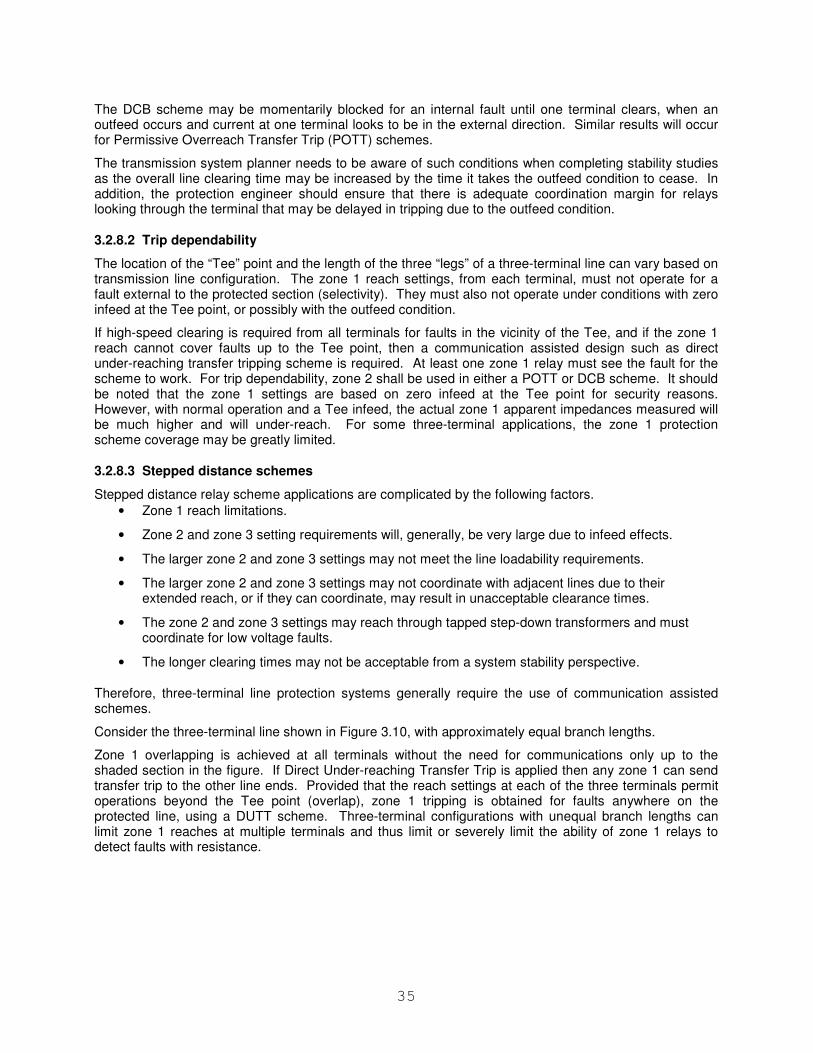
35
The DCB scheme may be momentarily blocked for an internal fault until one terminal clears, when an outfeed occurs and current at one terminal looks to be in the external direction. Similar results will occur for Permissive Overreach Transfer Trip (POTT) schemes.
The transmission system planner needs to be aware of such conditions when completing stability studies as the overall line clearing time may be increased by the time it takes the outfeed condition to cease. In addition, the protection engineer should ensure that there is adequate coordination margin for relays looking through the terminal that may be delayed in tripping due to the outfeed condition.
3.2.8.2 Trip dependability
The location of the “Tee” point and the length of the three “legs” of a three-terminal line can vary based on transmission line configuration. The zone 1 reach settings, from each terminal, must not operate for a fault external to the protected section (selectivity). They must also not operate under conditions with zero infeed at the Tee point, or possibly with the outfeed condition.
If high-speed clearing is required from all terminals for faults in the vicinity of the Tee, and if the zone 1 reach cannot cover faults up to the Tee point, then a communication assisted design such as direct under-reaching transfer tripping scheme is required. At least one zone 1 relay must see the fault for the scheme to work. For trip dependability, zone 2 shall be used in either a POTT or DCB scheme. It should be noted that the zone 1 settings are based on zero infeed at the Tee point for security reasons. However, with normal operation and a Tee infeed, the actual zone 1 apparent impedances measured will be much higher and will under-reach. For some three-terminal applications, the zone 1 protection scheme coverage may be greatly limited.
3.2.8.3 Stepped distance schemes
Stepped distance relay scheme applications are complicated by the following factors.
• Zone 1 reach limitations.
• Zone 2 and zone 3 setting requirements will, generally, be very large due to infeed effects.
• The larger zone 2 and zone 3 settings may not meet the line loadability requirements.
• The larger zone 2 and zone 3 settings may not coordinate with adjacent lines due to their extended reach, or if they can coordinate, may result in unacceptable clearance times.
• The zone 2 and zone 3 settings may reach through tapped step-down transformers and must coordinate for low voltage faults.
• The longer clearing times may not be acceptable from a system stability perspective.
Therefore, three-terminal line protection systems generally require the use of communication assisted schemes.
Consider the three-terminal line shown in Figure 3.10, with approximately equal branch lengths.
Zone 1 overlapping is achieved at all terminals without the need for communications only up to the shaded section in the figure. If Direct Under-reaching Transfer Trip is applied then any zone 1 can send transfer trip to the other line ends. Provided that the reach settings at each of the three terminals permit operations beyond the Tee point (overlap), zone 1 tripping is obtained for faults anywhere on the protected line, using a DUTT scheme. Three-terminal configurations with unequal branch lengths can limit zone 1 reaches at multiple terminals and thus limit or severely limit the ability of zone 1 relays to detect faults with resistance.
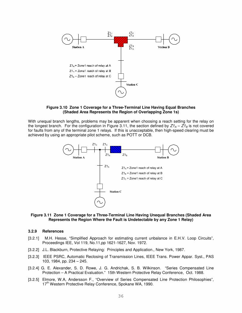
36
Figure 3.10 Zone 1 Coverage for a Three-Terminal Line Having Equal Branches (Shaded Area Represents the Region of Overlapping Zone 1s)
With unequal branch lengths, problems may be apparent when choosing a reach setting for the relay on the longest branch. For the configuration in Figure 3.11, the section defined by Z1A – Z1B is not covered for faults from any of the terminal zone 1 relays. If this is unacceptable, then high-speed clearing must be achieved by using an appropriate pilot scheme, such as POTT or DCB.
Station BStation A
Station C
Z1C Z1C
Z1A Z1B
Z1A = Zone1 reach of relay at A
Z1B = Zone1 reach of relay at B
Z1C = Zone1 reach of relay at C
Z1A
Figure 3.11 Zone 1 Coverage for a Three-Terminal Line Having Unequal Branches (Shaded Area Represents the Region Where the Fault is Undetectable by any Zone 1 Relay)
3.2.9 References
[3.2.1] M.H. Hesse, “Simplified Approach for estimating current unbalance in E.H.V. Loop Circuits”, Proceedings IEE, Vol 119, No.11,pp 1621-1627, Nov. 1972.
[3.2.2] J.L. Blackburn, Protective Relaying: Principles and Application., New York, 1987.
[3.2.3] IEEE PSRC, Automatic Reclosing of Transmission Lines, IEEE Trans. Power Appar. Syst., PAS 103, 1984, pp. 234 – 245.
[3.2.4] G. E. Alexander, S. D. Rowe, J. G. Andrichak, S. B. Wilkinson. “Series Compensated Line Protection – A Practical Evaluation.” 15th Western Protective Relay Conference, Oct. 1988.
[3.2.5] Elmore, W.A, Andersson F., “Overview of Series Compensated Line Protection Philosophies”, 17
th Western Protective Relay Conference, Spokane WA, 1990.
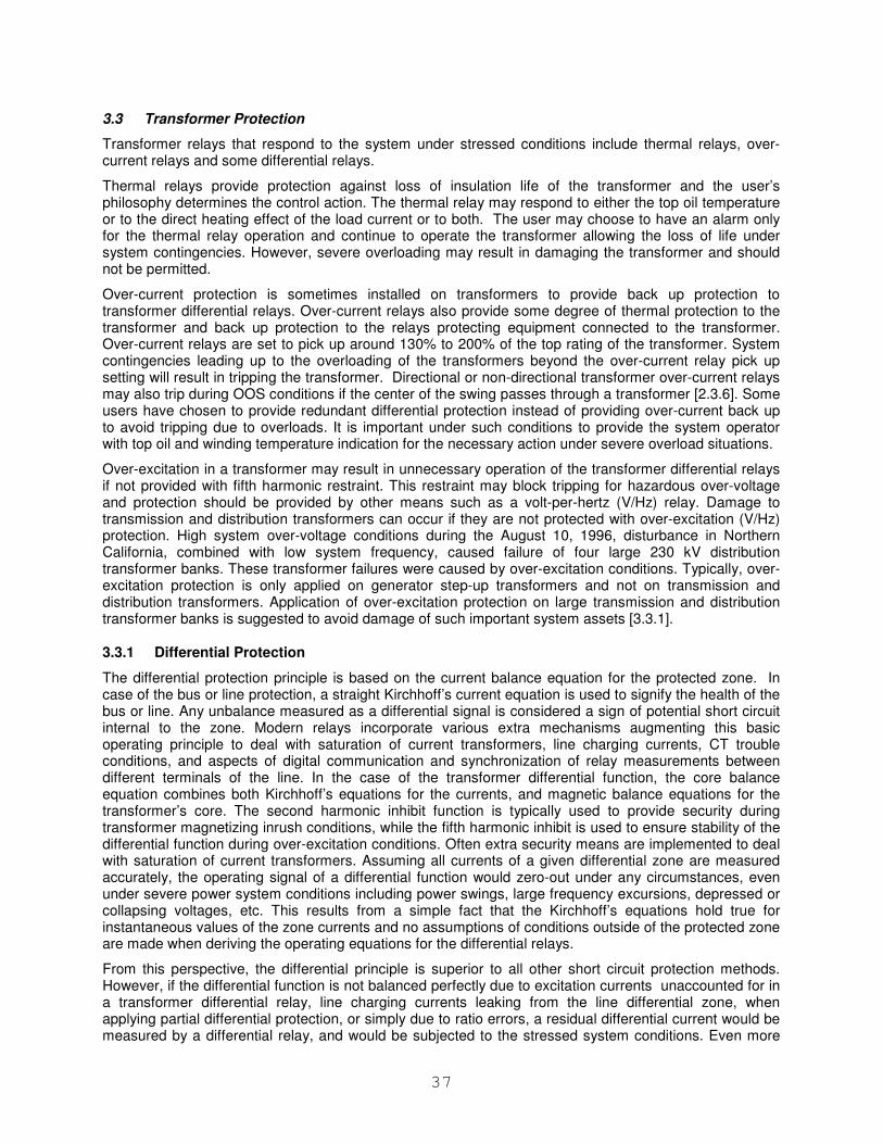
37
3.3 Transformer Protection
Transformer relays that respond to the system under stressed conditions include thermal relays, over-current relays and some differential relays.
Thermal relays provide protection against loss of insulation life of the transformer and the user’s philosophy determines the control action. The thermal relay may respond to either the top oil temperature or to the direct heating effect of the load current or to both. The user may choose to have an alarm only for the thermal relay operation and continue to operate the transformer allowing the loss of life under system contingencies. However, severe overloading may result in damaging the transformer and should not be permitted.
Over-current protection is sometimes installed on transformers to provide back up protection to transformer differential relays. Over-current relays also provide some degree of thermal protection to the transformer and back up protection to the relays protecting equipment connected to the transformer. Over-current relays are set to pick up around 130% to 200% of the top rating of the transformer. System contingencies leading up to the overloading of the transformers beyond the over-current relay pick up setting will result in tripping the transformer. Directional or non-directional transformer over-current relays may also trip during OOS conditions if the center of the swing passes through a transformer [2.3.6]. Some users have chosen to provide redundant differential protection instead of providing over-current back up to avoid tripping due to overloads. It is important under such conditions to provide the system operator with top oil and winding temperature indication for the necessary action under severe overload situations.
Over-excitation in a transformer may result in unnecessary operation of the transformer differential relays if not provided with fifth harmonic restraint. This restraint may block tripping for hazardous over-voltage and protection should be provided by other means such as a volt-per-hertz (V/Hz) relay. Damage to transmission and distribution transformers can occur if they are not protected with over-excitation (V/Hz) protection. High system over-voltage conditions during the August 10, 1996, disturbance in Northern California, combined with low system frequency, caused failure of four large 230 kV distribution transformer banks. These transformer failures were caused by over-excitation conditions. Typically, over-excitation protection is only applied on generator step-up transformers and not on transmission and distribution transformers. Application of over-excitation protection on large transmission and distribution transformer banks is suggested to avoid damage of such important system assets [3.3.1].
3.3.1 Differential Protection
The differential protection principle is based on the current balance equation for the protected zone. In case of the bus or line protection, a straight Kirchhoff’s current equation is used to signify the health of the bus or line. Any unbalance measured as a differential signal is considered a sign of potential short circuit internal to the zone. Modern relays incorporate various extra mechanisms augmenting this basic operating principle to deal with saturation of current transformers, line charging currents, CT trouble conditions, and aspects of digital communication and synchronization of relay measurements between different terminals of the line. In the case of the transformer differential function, the core balance equation combines both Kirchhoff’s equations for the currents, and magnetic balance equations for the transformer’s core. The second harmonic inhibit function is typically used to provide security during transformer magnetizing inrush conditions, while the fifth harmonic inhibit is used to ensure stability of the differential function during over-excitation conditions. Often extra security means are implemented to deal with saturation of current transformers. Assuming all currents of a given differential zone are measured accurately, the operating signal of a differential function would zero-out under any circumstances, even under severe power system conditions including power swings, large frequency excursions, depressed or collapsing voltages, etc. This results from a simple fact that the Kirchhoff’s equations hold true for instantaneous values of the zone currents and no assumptions of conditions outside of the protected zone are made when deriving the operating equations for the differential relays.
From this perspective, the differential principle is superior to all other short circuit protection methods. However, if the differential function is not balanced perfectly due to excitation currents unaccounted for in a transformer differential relay, line charging currents leaking from the line differential zone, when applying partial differential protection, or simply due to ratio errors, a residual differential current would be measured by a differential relay, and would be subjected to the stressed system conditions. Even more

38
importantly, auxiliary functions of a differential relay such as harmonic inhibits, CT saturation detectors, frequency-tracking algorithms in the case of microprocessor-based relays, would respond to stressed system conditions and potentially have an impact on the security and/or dependability of protection.
The impact of off-nominal frequencies on phasors is described in section 3.1. Specific issues related to transformer differential protection are described below.
3.3.1.1 Harmonic restraint in transformer differential schemes
Traditionally, transformer differential relays use second and fifth harmonics to inhibit magnetizing inrush, and over-excitation, respectively. Under extreme system events transformers may be exposed to multiple cases of inrush (fault recovery inrush, out of step breaker closure) and over-excitation (elevated voltages, low frequency). The ability to restrain correctly under such conditions is important to avoid cascading tripping during major system disturbances. During off-nominal system frequencies, the harmonics that signify inrush or over-excitation move, following the frequency of the fundamental component. As the fundamental frequency changes by 1Hz, the position of the second harmonic changes by 2Hz and the position of the fifth harmonic changes by 5Hz. A transformer relay must compensate for this phenomenon, or else both security and dependability problems could occur. Figures 3.12 and 3.13 illustrate this effect by showing the frequency response of sample second and fifth harmonic filters under nominal and off-nominal frequencies, respectively, both for full-cycle Fourier filters.
Two effects take place. Firstly, while operating normally when perfectly tuned to the actual harmonic, the filters remove entirely the dominant fundamental frequency component (zero gain). Under off-nominal frequencies, some portion of the fundamental frequency component will leak in to the harmonic measurement. Given the relatively low inhibit thresholds, this leads to a problem with dependability of protection should an internal transformer fault occur in response to severe system events (e.g. elevated and long lasting power swing through currents). Secondly, the harmonic filters may underestimate the actual harmonic levels under off-nominal frequencies should inrush or over-excitation actually take place. This may lead to deterioration in protection security.
It should be noticed that the errors in harmonic measurements explained above are typically oscillatory in nature. This means dependability is not an issue; a delayed operation is more likely to happen (although the exact impact is subject to the details of the inner workings of a given relay).
Security of protection may be truly impacted, though. With multiple reclose operations potentially leading to magnetizing/sympathetic inrush, prolonged over-excitation conditions, or power swings, inaccurate harmonic measurements may jeopardize the security of the transformer protection.
0 1 2 3 4 5 6 70
0.5
1
1.5
2n
d h
arm
on
ic filt
er
0 1 2 3 4 5 6 70
0.5
1
1.5
5th
ha
rmo
nic
filt
er
frequency, pu
Fundamental Frequency Component Zeroed-out
Fundamental Frequency Component Zeroed-out
5th HarmonicMeasured Correctly
2nd HarmonicMeasured Correctly
Figure 3.12 Illustration of 2nd
and 5th
Harmonic Measurements Under Nominal Frequency
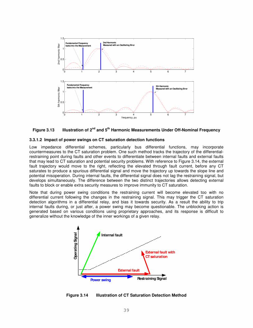
39
0 1 2 3 4 5 6 70
0.5
1
1.5
2n
d h
arm
on
ic filt
er
0 1 2 3 4 5 6 70
0.5
1
1.5
5th
ha
rmo
nic
filt
er
frequency, pu
Fundamental Frequency leaks into the Measurement
2nd HarmonicMeasured with an Oscillating Error
5th HarmonicMeasured with an Oscillating Error
Fundamental Frequency leaks into the Measurement
Figure 3.13 Illustration of 2nd
and 5th
Harmonic Measurements Under Off-Nominal Frequency
3.3.1.2 Impact of power swings on CT saturation detection functions
Low impedance differential schemes, particularly bus differential functions, may incorporate countermeasures to the CT saturation problem. One such method tracks the trajectory of the differential-restraining point during faults and other events to differentiate between internal faults and external faults that may lead to CT saturation and potential security problems. With reference to Figure 3.14, the external fault trajectory would move to the right, reflecting the elevated through fault current, before any CT saturates to produce a spurious differential signal and move the trajectory up towards the slope line and potential misoperation. During internal faults, the differential signal does not lag the restraining signal, but develops simultaneously. The difference between the two distinct trajectories allows detecting external faults to block or enable extra security measures to improve immunity to CT saturation.
Note that during power swing conditions the restraining current will become elevated too with no differential current following the changes in the restraining signal. This may trigger the CT saturation detection algorithms in a differential relay, and bias it towards security. As a result the ability to trip internal faults during, or just after, a power swing may become questionable. The unblocking action is generated based on various conditions using proprietary approaches, and its response is difficult to generalize without the knowledge of the inner workings of a given relay.
Restraining Signal
Opera
tin
g S
igna
l
External fault with
CT saturation
External fault
Power swing
Internal fault
Figure 3.14 Illustration of CT Saturation Detection Method
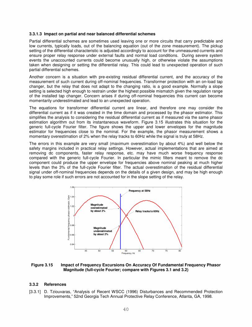
40
3.3.1.3 Impact on partial and near balanced differential schemes
Partial differential schemes are sometimes used leaving one or more circuits that carry predictable and low currents, typically loads, out of the balancing equation (out of the zone measurement). The pickup setting of the differential characteristic is adjusted accordingly to account for the unmeasured currents and ensure proper relay response under external faults and normal load conditions. During severe system events the unaccounted currents could become unusually high, or otherwise violate the assumptions taken when designing or setting the differential relay. This could lead to unexpected operation of such partial differential schemes.
Another concern is a situation with pre-existing residual differential current, and the accuracy of the measurement of such current during off-nominal frequencies. Transformer protection with an on-load tap changer, but the relay that does not adapt to the changing ratio, is a good example. Normally a slope setting is selected high enough to restrain under the highest possible mismatch given the regulation range of the installed tap changer. Concern arises if during off-nominal frequencies this current can become momentarily underestimated and lead to an unexpected operation.
The equations for transformer differential current are linear, and therefore one may consider the differential current as if it was created in the time domain and processed by the phasor estimator. This simplifies the analysis to considering the residual differential current as if measured via the same phasor estimation algorithm out from its instantaneous waveform. Figure 3.15 illustrates this situation for the generic full-cycle Fourier filter. The figure shows the upper and lower envelopes for the magnitude estimator for frequencies close to the nominal. For the example, the phasor measurement shows a momentary overestimation of 2% when the relay tracks to 60Hz while the signal is truly at 58Hz.
The errors in this example are very small (maximum overestimation by about 4%) and well below the safety margins included in practical relay settings. However, actual implementations that are aimed at removing dc components, faster relay response, etc. may have much worse frequency response compared with the generic full-cycle Fourier. In particular the mimic filters meant to remove the dc component could produce the upper envelope for frequencies above nominal peaking at much higher levels than the 3% of the full-cycle Fourier filter. The actual overestimation of the residual differential signal under off-nominal frequencies depends on the details of a given design, and may be high enough to play some role if such errors are not accounted for in the slope setting of the relay.
45 50 55 60 65 70 75 80
0.94
0.96
0.98
1
1.02
1.04
1.06
Frequency, Hz
Fu
nd
am
en
tal f
req
ue
ncy p
ha
so
r e
stim
ato
r, G
ain
Frequency at 58Hz
Relay tracks to 60Hz
Magnitude overestimated by about 2%
Magnitude underestimated by about 2%
Figure 3.15 Impact of Frequency Excursions On Accuracy Of Fundamental Frequency Phasor Magnitude (full-cycle Fourier; compare with Figures 3.1 and 3.2)
3.3.2 References
[3.3.1] D. Tziouvaras, “Analysis of Recent WSCC (1996) Disturbances and Recommended Protection Improvements,” 52nd Georgia Tech Annual Protective Relay Conference, Atlanta, GA, 1998.
41
3.4 Generator Protection
Protective devices applied for generator protection and system backup protection may trip during a system disturbance. It is important that these relays be applied properly so that they protect the generator but help preserve system integrity by not tripping unnecessarily.
The paper [3.4.1] reports on generator relay operations during some major system events. Major causes of trips reported are described next.
3.4.1 Under-voltage
Under-voltage was a direct cause of unit trips in many of the reported disturbances. Nuclear units are particularly vulnerable during prolonged disturbances with depressed voltage because the under-voltage protection of critical motors is often set close to 0.9 per unit voltage. In other cases depressed auxiliary bus voltages caused mechanical problems, which resulted in unit trips. Low voltages observed during loss of synchronism could also cause under-voltage protection relays of auxiliary plant equipment to operate, depending on the pickup and time delay settings associated with under-voltage relays. System contingency studies should include performance of generating units to under-voltage.
3.4.2 Backup Protection
System phase backup protection using voltage restrained or voltage controlled relays may trip during swings or prolonged system under-voltages. Backup distance relaying may also trip during stressed conditions, depending on their settings. The operation of the backup generator distance relay is more predictable than the voltage-controlled or voltage-restraint generator backup relays and they should be preferred.
3.4.3 Incorrect Tripping on Load Rejection
During load rejection, hydro units should not be locked out. However, they may trip due to third harmonic neutral under-voltage, fundamental frequency neutral over-voltage, over-voltage and over-frequency relays. Settings and relay design should be reviewed for load rejection conditions.
3.4.4 Under-frequency
Under-frequency load shedding schemes should be coordinated with the under-frequency settings applied to protect the turbine so that system integrity can be maintained without tripping generators. Hydro generators do not require under-frequency protection but a number of them have been applied with this protection without under-voltage supervision and have tripped undesirably during a disturbance.
3.4.5 Loss of Field
Loss of field relays may pick up during stable swings or under-excited conditions. They may also trip because of miss-coordination with excitation control and limit settings. Some loss of field relay trips occurred because the units were on manual control and the excitation output was frequency dependant (shaft driven exciters).
Where possible, units should be kept on automatic voltage regulator. Coordination between excitation controls, exciter protection and exciter limits and protective relay settings should be checked. Periodic testing of steady state and dynamic coordination of excitation system controls and protective relays is suggested. Volts per hertz relays and over-voltage relays have also initiated undesirable trips due to miss-coordination with excitation system controls.
3.4.6 Over-Excitation
During the August 10, 1996, disturbance, the Northern California island experienced high system-over-voltage conditions (~10%–20%), because of excessive reactive power from the unloaded 500 kV transmission system and inability of system controls to maintain acceptable system voltages. High system voltages, combined with low frequency, caused the generators to operate in their under-excited region, trying to control the system voltage by absorbing large amounts of VARs from the system. As a
42
consequence of this, V/Hz limiters overrode the Minimum Excitation Limiters (MEL) and played a major role in the tripping of a number of large generating units. A study revealed that units with modern excitation systems with V/Hz limiters tripped by loss-of-field protection. The units that were equipped with older voltage regulators without V/Hz limiters tripped by generator V/Hz protection relays.
3.4.7 Out-of-Step
Severe system disturbances often involve multiple events with depressed system voltages, switching events and system oscillations. In addition, under abnormal system conditions such as under-frequency, the relay characteristics may vary from ideal. Under these circumstances, the impedance trajectory may enter the modified OOS relay tripping characteristic for some situations where the machine is not necessarily out of step, causing generator tripping and possibly worsening overall system conditions. Detailed studies of performance under severe multiple contingencies must balance the risk of undesirable tripping against the risk of damage to the machine.
Instantaneous directional over-current relays could also operate during OOS conditions and cause uncontrolled tripping of generating plants. During the August 10, 1996 WECC disturbance, two large units tripped uncontrollably during an OOS condition by instantaneous directional over-current relays applied to protect a short line section from the switchyard to the high-side of the generator step-up transformers [2.3.7].
3.4.8 Gas Turbine Generator Motoring
A combustion gas turbine generator can be operated in the reverse direction, acting as a motor, for example during power plant start-ups. During motoring, gas turbine generators consume high power (up to 25% of their rated MVA) from the transmission system they are connected to and, therefore, may contribute to system low voltage conditions and even cause voltage collapse.
3.4.9 Unknown Causes The causes of many turbine generator trips are not identified. This is because many plants have limited annunciator displays and do not have sequence of event or oscillography recorders. In addition, plant operators and maintenance personnel may not be trained to record targets and alarms and to collect the fault information available in modern digital relay and control devices.
3.4.10 References
[3.4.1] S. Patel, K. Stephan, M. Bajpai, R. Das, T. J. Domin, E. Fennell, J. D. Gardell, I. Gibbs, C. Henville, P. M. Kerrigan, H. J. King, P. Kumar, C. J. Mozina, M. Reichard, J. Uchiyama, S. Usman, D. Viers, D. Wardlow, M. Yalla, “Performance of generator protection during major system disturbances”, IEEE Trans. Power Delivery, Vol. 19-4, October 2004, pp. 1650-1662.
3.5 Bus Protection
When accomplished by means of the differential principle, busbar protection schemes are immune to extreme system conditions. Frequency excursions, voltage abnormalities and power swings do not violate the current balance equation, being the core of the differential principle. Therefore differential bus protection schemes are not a cause for concern, from the security point of view.
From the dependability perspective, power swings may impair capability to detect internal faults, cause delays or decrease sensitivity compared with normal operating conditions. This is particularly true when using restrained differential relays. Large through currents due to power swings produce extra restraint and/or may inadvertently trigger CT saturation detection/security means in a given bus relay. This is explained in section 3.3.1.
Some relays may use under-voltage trip supervision, or over-current trip supervision. These are a means of dealing with CT/wiring/relay failures. If an unattended CT/wiring/relay problem occurs and does not result in an immediate misoperation due to the under-voltage or over-current supervision, abnormal system events may trigger such weakened bus protection schemes towards a “delayed misoperation”. For example, a wiring problem may result in an unbalanced differential current; under-voltage supervision
43
may prevent an immediate misoperation making the scheme effectively impaired for an extended period of time; a subsequent power swing depressing the voltage may result in a “delayed misoperation” due to such a pre-existing problem.
Some less critical buses may be protected by a directional (interlocking) scheme, particularly if the fault current flow directions are known beforehand, such as in sub-transmission or distribution networks. In the simplest case, an internal bus fault is declared if an incomer sees excessive current and none of the feeders see a fault level current.
Such directional schemes are relatively secure, subject to the performance of their over-current and directional functions under stressed conditions. They would suffer from the same dependability problems as the differential relays: a large through fault current due to a swing would limit sensitivity or prevent operation on internal faults occurring during power swings, cold load pickup or other abnormal load patterns.
3.6 Shunt Capacitor and Reactor Protection
System characteristics, such as unbalance and harmonics which are prevalent in stressed conditions, can adversely affect shunt capacitor protection and control. Stressed conditions often result in abnormally unbalanced systems. These may be due to area loads, untransposed lines or undetected open or partially open phases in equipment such as switches and breakers.
This system unbalance will be magnified by the order of three in the neutral of shunt capacitor banks. If the unbalance protection is not compensated or poorly compensated, the protection may incorrectly detect this as a unit failure and trip the capacitor bank. Abnormally high harmonics are also often observed during stressed conditions. These harmonics may adversely affect the instrument transformers and the relays. The measured quantities can become inaccurate due to saturation. The relay could also improperly process harmonically rich quantities. For example, fifth harmonic voltages and currents may appear as negative sequence quantities to a relay and cause it to falsely operate. During stressed conditions, the system impedance will usually increase due to the outage of generators and lines. This can cause a severe retuning of the power system and capacitor bank such that a new harmonic resonant point is created at the third, fifth or seventh harmonic. If this resonance occurs, the area harmonic load at this frequency will be greatly amplified and result in unexpected operations for the same reasons described earlier but in a more dramatic fashion.
3.7 Feeder Protection
Feeder protection is typically applied to radial distribution lines, 5 – 35 kV. The most common relaying applied to feeders are circuit reclosers, and phase and ground over-current relays. Instantaneous and inverse time over-current elements for both phase and ground are the most common scheme. Multifunction microprocessor relays may also perform other system protection functions, such as under-voltage or under-frequency load shedding, but these will not be discussed in this section which deals with the protection of the feeder only.
The criteria for determining the settings of the over-current relays are generally based on the expected feeder load or conductor thermal limits, and coordination with downstream devices.
Major system disturbances on the transmission network may cause voltage and frequency variations on the distribution network. Uncontrolled tripping by feeder relays, disconnecting load from the transmission network may further aggravate the generation/load balance. There is some evidence of feeder relay trips during the 2003 blackout event that did not originate from load-shed devices but from over-current trips.
What is likely to have occurred is the stalling of air conditioning and refrigeration and similar motors. This type of motor stalls very quickly and can cause distribution feeders to be opened by over-current protection two to three seconds after the motors stall. If the feeders hold, the stalled refrigeration motors will remain connected for ten to twenty seconds until internal overload sensors time out and switch the motors off. This occurs slowly because the usual 600% to 700% motor locked rotor current is limited to not much more than rated current when the voltage is low. When the stalled motors remain connected to the grid for 10 to 20 seconds, there is very high risk of cascade stalling of additional motors or angular instability.
44
Furthermore, reclosing without overriding cold-load pick-up may fail to successfully restore an un-faulted feeder into service. In addition, load unbalance could increase due to different types of loads on different phases during overload conditions and cause trips of sensitive ground or negative sequence over-current elements.
Another issue to consider for feeder protection is restoration. If the feeder is tripped by over-current rather than controlled load shed, the recloser is locked out and automatic restoration may not be possible.
While tripping on overload during voltage sags could be avoided by increased settings of the over-current elements, the risk of cable failures due to higher current and/or voltage swells has to be considered. One utility reported over 100 direct buried cable failures during and after the 2003 blackout event, which represented 25% of total number of cable failures in any calendar year.
3.8 Motor Protection
Protective elements applied for motor protection may be adversely impacted during a system disturbance. It is important that these protective elements be applied properly so that they protect the motor and also allow maximum continuity of service to the motor and thus to the process.
IEEE Guide for AC Motor Protection [3.8.1] provides information on impacts of abnormal power supply to motors. The abnormal supply would result from a major system disturbance. The following effects are general for all motors, induction and synchronous. Some disturbance symptoms will have additional effects on synchronous motors, and those effects are also noted.
3.8.1 Under-voltage
Motor supply under-voltage may influence motor operation and protection as follows:
• As motors may be considered constant kVA loads, a decrease in voltage causes an increase in current with the load held constant. This causes an increase in motor heating due to greater I
2R
losses. Decreased voltage at motor starting causes less current to be drawn (as compared to rated voltage starts), and therefore less torque to be developed. This may result in developed torque to be less than breakdown torque, stalling the motor, which may cause the locked rotor protection to trip.
• The impedance of the motor decreases as voltage level decreases and current level increases. If the impedance decrease is within the impedance element’s setting, it may cause the protection to operate.
• In synchronous motors, more field current may be developed to compensate for the voltage drop (raise VAr output in attempt to raise terminal voltage). This may cause field current-based protection (AC or DC) to trip.
• In synchronous motors, the decrease in field current, combined with high loading, may cause stability issues that may cause the out of step protection to trip.
3.8.2 Under-frequency
Motor supply Under-frequency may effect motor operation and protection as follows:
• Lower motor speed may compromise motor cooling (decreased ventilation). This may cause temperature-based thermal protection to trip.
• As the frequency decreases, if the voltage is held at nominal or increases, over-fluxing (v/Hz) may result. If so equipped, this may cause volts/Hertz protection to trip.
• In synchronous machines, if frequency is too low, the motor may fail to pull into synchronism causing a trip on out of step or rotor thermal overload due to the start sequence taking too long (rotor thermal limited during starting)
45
3.8.3 Over-voltage
Motor supply over-voltage may effect motor operation and protection as follows:
• As motors may be considered constant kVA loads, an increase in voltage causes a decrease in current with the load held constant. The magnetization currents increase, but not as much as the load current decreases, so there is an overall current decrease. As long as dielectric limits are not encroached upon, this does not damage the motor. This causes a decrease in motor heating due to lower I
2R losses.
• Increased voltage at motor starting causes more current to be drawn (as compared to rated voltage starts), and therefore more torque to be developed.
• The impedance of the motor increases as the voltage level increases and the current level decreases.
• In synchronous motors, less field-current may be developed to compensate for the voltage rise (lower VAr output in attempt to lower terminal voltage). This may cause the loss of field impedance-based protection to trip.
3.8.4 References
[3.8.1] “Guide for AC Motor Protection,” IEEE C37.96-2000.
3.9 Under-frequency Load Shedding Protection
During normal operating conditions the frequency is continuously maintained at the nominal value by either the fast operation of the unit speed governors or by the secondary power-frequency regulation which, through slower dynamics, operates the participating units within the allowed control bands to compensate the load variation. The frequency support is also provided by the surrounding systems through interconnections.
Aggravated operating conditions (e.g. faults, overloads) may lead to cascading outages. As those outages may cause mismatch between the active power generated and the load, regulating systems above could lose the system controllability. In large interconnections, this usually happens when the power system separates into islands with an unbalance between generation and load, causing the frequency to deviate from the nominal value. A quick, simple, and reliable way to re-establish the active power balance (when the load is larger than generation) is to shed the load by means of under-frequency relays. Under-frequency load shedding is performed to minimize the risk of a further uncontrolled system separation, loss of generation, or system shutdown. If sufficient load is shed to preserve interconnections and keep generators on line, the system can be restored rapidly.
Relay functions may include a combination of frequency, rate-of-change-of-frequency, and time delay. Typical load shedding schemes are based on predetermined system scenarios. There are a large variety of practices in designing load shedding schemes based on the characteristics of a particular system and the utility philosophy [3.9.1]. For interconnected systems, it may be necessary to coordinate the philosophy and settings among all utilities across the entire system. The following parameters need to be considered when designing a scheme:
• Number of load shedding steps
• Frequency setting for the highest frequency step and difference between consecutive steps
• Time delays for each step and for the overall plan
• Percentage/amount of load to be shed at each step and total amount of load for shedding
The impact of stressed system conditions on under-frequency relays will be discussed next. Overloading of the generators during a disturbance is followed by considerable decrease in system voltages, which causes an instantaneous decrease of the constant impedance load power. After the initial disturbance,
46
the generator governing system utilizes the spinning reserve (if available), the generator excitation system responds to the voltage changes, and the load power changes with frequency and voltage.
The active power for the constant impedance load significantly decreases as the load voltage decreases [3.9.2]. As a consequence, during power system disturbances accompanied by a significant voltage drop, active power consumption is reduced, consequently, having a positive effect of reducing the power deficit and the frequency drop.
The following need to be considered in designing an under-frequency load shedding scheme:
• Under-frequency load shedding with simultaneous unloading of transmission lines can cause over-voltages and diminish results of load shedding [3.9.3].
• In cable networks with high shunt capacitance, uncontrolled load shedding may cause a voltage increase which can make load shedding ineffective [3.9.4].
Furthermore, the following issues need to be considered when designing a load shedding scheme (3.9.5):
• The load designated for shedding depends on the assumed load distribution. Designated loads will be disconnected with frequency relays, but the planned amount of load may not be shed, resulting in under-shedding or over-shedding. For example, a designated load may be outside of the isolated region or include a few large industrial customers which are not operating.
• Load is shed in discrete steps and the exact amount of load may not be shed, which may lead to over-shedding or under-shedding. The under-shedding can lead to a slow recovery of the frequency or the frequency can remain between two consecutive steps. A scheme with time delayed frequency relays may be implemented, but frequency recovery is prolonged. To increase the number of load shedding steps without limit (to achieve a continuous function) is not practical, delays the frequency recovery, and causes selectivity problems for the relays.
• Available spinning reserve and its response need to be considered to optimize load shedding.
As under-frequency load shedding plans are based on studies of a system’s dynamic performance, given the greatest probable imbalance between load and generation, improvements could be achieved by implementing adaptive settings based on actual system conditions. This is addressed in section 5.9.
3.9.1 References
[3.9.1] IEEE PC37.117, “Guide for the Application of Protective Relays Used for Abnormal Frequency Load Shedding and Restoration,” 2006.
[3.9.2] J. Arrilaga, et. al., Computer Modelling of Electrical Power Systems, John Willey and Sons, page 220 - 222, 1983.
[3.9.3] L. H. Fink, et al, "Emergency Control Practices," IEEE Transactions on PAS, Vol. 104, pp. 2336-2441, Sep. 1985.
[3.9.4] Y. Ohura, et al, "Microprocessor Based Stabilizing Control Equipment for Survival of Isolated Mid-City Power System," IEEE Transactions PWRD, Vol. 1, pp. 99-104, October 1986.
[3.9.5] A. Apostolov, D. Novosel, and D.G. Hart, "Intelligent Protection and Control During Power System Disturbance," Proceedings of the American Power Conference, 56th Annual Meeting, Chicago, April 25-27, 1994, Volume 56-II, pp. 1175-1181
3.10 System Integrity Protection Scheme (SIPS)
SIPS are intended to take pre-planned actions under stressed system conditions within a certain time period. SIPS are also called Special Protection Schemes (SPS) or Remedial Action Schemes (RAS). The intended actions and required timing are determined through extensive system modeling studies.
Remedial actions may fail to occur or occur more slowly than planned (a dependability failure). Perhaps the specific system conditions were not foreseen as a credible system failure, so that no SIPS was ever designed for those conditions. The continuing stressed system conditions may then be interpreted
47
incorrectly by relays applied for equipment protection, operation of which would be undesirable (a security failure), resulting in cascading outages.
3.10.1 References
[3.10.1] M. Begovic, V. Madani, and D. Novosel, “System Integrity Protection Systems,” IREP Symposium for Bulk Power Systems Dynamics and Control VII, Charleston, Georgia, August 2007.
3.11 Dependability and Security Balance
The art of protective relaying is a constant balance between capacity to detect abnormal conditions in a protected asset, and the ability to restrain from operation under all the other conditions. Considered separately, dependability and security of protection are easy targets. It is the necessity to satisfy both requirements simultaneously that makes protective relaying a challenging technical field.
When taken to the level of an individual relay function such as an impedance element, and considered from the perspective of stressed system conditions such as a power swing, security is the prevailing concern. Historically speaking, line protection exposed to elevated load levels or power swings have been considered points for major blackouts. Therefore, securing the protection function from spurious operations under unusual, system-generated input signal patterns is the primary objective. Using blinders or power swing blocking elements are just two examples of such countermeasures. Again, when considered in separation from the dependability aspect of protective relaying, securing relays under stressed system conditions is not a difficult task.
Protection relays, however, are meant to protect assets under all circumstances, including abnormal system events, and must retain a certain level of dependability at all times. A line with an increased load or under a swing condition may still endure a fault. Moreover, it is more likely to experience a fault due to conductor sagging during overloads, or the over-voltage effect of a power swing. Such faults are to be detected and cleared accordingly, regardless of the encroaching loads or ongoing power swings.
On one level, the issue of dependability is related to the nature of countermeasures applied for the effects of stressed system conditions. For example, when blocking distance protection from a power swing detection function, one shall ensure that an unblocking function is built in and will trigger should a fault occur during the swing or a backup function is available to detect such faults. In case of a distance protection of transmission lines, a time-delayed self-polarized narrow quadrilateral function may be used to detect faults under power swings. A negative-sequence directional comparison scheme is yet another good choice, covering all but perfectly symmetrical three-phase faults.
On a different level, the ability of traditional protection methods to operate correctly may be challenged under severe system events even if these functions are not purposefully inhibited for security reasons. Consider the concept of memory polarization for the impedance comparators: it works assuming the two equivalent systems are not out of phase; and therefore, it fails to retain dependability under unstable power swings. In general, the concept of memory does not work under swings and other system transients. Being unable to rely on memory polarization, line distance relays would have a problem distinguishing close in forward from close in reverse faults. Cross-polarization would help under stable swings, but the healthy phase voltages swing while the faulted phases do not. Under unstable swings the rotating healthy phase voltages do not reflect the emf driving the fault current in the faulted phases, hence they fail to provide meaningful polarization. Negative-sequence directional over-current comparison is a solution, but how do we cover three-phase faults, or what if one of the phases is opened during single pole tripping and reclosing?
In general, the protection function faces both security and dependability problems when pushed beyond their regular design limits. To continue providing protection under severe system conditions calls for more sophisticated relaying methods. Such methods in turn are more difficult to set and verify. Moreover, they do not provide the same high level of performance, but rather avoid impairing the protection system response too much.
48
4 Field Experience and Examples
4.1 North American Electric Reliability Council (NERC) Analysis of August 14, 2003 Blackout
On August 14, 2003, large portions of the Midwest and Northeast United States and Ontario, Canada, experienced an electric power blackout. The outage affected an area with an estimated 50 million people and 61,800 megawatts (MW) of electric load in the states of Ohio, Michigan, Pennsylvania, New York, Vermont, Massachusetts, Connecticut, New Jersey and the Canadian province of Ontario.
The triggering events were the trip of a generating unit in Ohio due to an overloaded excitation system, the trips of 345 kV lines in Northern Ohio that sagged into trees and vegetation, unfaulted lines tripping on load, cascading line trips, generators tripping for many reasons, system breakup and island collapse. As the line trip-outs overloaded the grid, some operators were unaware of the unfolding events, SCADA systems became inoperative and State Estimation programs did not provide the necessary warnings
This section summarizes the work NERC and its Regions are doing to implement recommendations developed by the Blackout Investigators of the U.S.-Canada Power System Outage Task Force. This summary draws from publications that can be accessed from the NERC website www.nerc.com
The US-Canada report [1.1.1] divided recommendations into three groups:
• Correct the Direct Causes
• Develop strategic initiatives to strengthen compliance, readiness, vegetation management
• Develop technical initiatives to prevent or mitigate future cascading blackouts with regards to operations planning, protection, monitoring and control
The recommendations with regards to correcting the direct causes are implemented. The development of strategic initiatives is the basis for standards being completed through the NERC Standards Process. NERC formed the System Protection and Control Task Force (SPCTF) to develop the initiatives necessary to mitigate future cascades by developing a “defense in depth” strategy for protection, monitoring and control.
The Key System Protection Issues identified by the U.S. Canada Task Force Blackout Investigators were:
• Unintended tripping due to load during extreme system contingencies.
• Lack of safety nets such as under-voltage relay schemes
• Improper coordination between generation protection/control and the transmission system
• In-effectiveness of under-frequency load shedding schemes once electrical islands were formed.
The blackout investigators found that zone 3 relays contributed to the acceleration of the blackout. After the initial phase of the event, where lines tripped due to tree contact, lines began to trip without a fault being present. The system remained stable at this moment and yet lines tripped by relaying responding to increasing line power flow. Also, the cascade might have been limited to the local area if an under-voltage load shedding scheme was in place within the Cleveland/Akron area prior to loss of the 345-kV line.
As a result of the investigation five particular protection and control recommendations (Recommendation 21a) were published in the U.S. Canada report:
• Evaluate the settings of zone 3 relays on all transmission lines of 230 kV and higher.
• Evaluate zone 2 relays set to operate like zone 3’s.
• Evaluate the feasibility and benefits of installing under-voltage load shedding.
• Evaluate system protection and control planning standards within one year taking account of the lessons learned.
• Broaden the review to include operationally significant 115-kV and 138-kV lines.
49
In concert with the U.S. Canada Task Force, NERC Recommendations 8a and 8b, Improve System Protection to Limit Cascading Outages were approved by the NERC Board of Directors in December 2003.
NERC Recommendation 8a: Zone 3 Settings
All transmission owners shall evaluate the zone 3 relay settings on all transmission lines operating at 230 kV and above for the purpose of verifying that each zone 3 relay is not set to trip on load under extreme emergency conditions. In each case that a zone 3 relay is set so as to trip on load under extreme conditions, the transmission operator shall reset, upgrade, replace, or otherwise mitigate the overreach of those relays as soon as possible and on a priority basis.
NERC Recommendation 8b: Under-voltage load shedding
Each regional reliability council shall complete an evaluation of the feasibility and benefits of installing under-voltage load shedding capability in load centers within the region that could become unstable as a result of being deficient in reactive power following credible multiple-contingency events. The regions are to complete the initial studies and report the results to NERC. The regions are requested to promote the installation of under-voltage load shedding capabilities within critical areas, as determined by the studies to be effective in preventing an uncontrolled cascade of the power system.
4.1.1 Loadability Requirements
Following is the definition of Emergency Ampere Rating — “The highest seasonal ampere circuit rating (that most closely approximates a 4-hour rating) that must be accommodated by relay settings to prevent incursion.” That rating will typically be the winter short-term (four-hour)emergency rating of the line and series elements. The line rating should be determined by the lowest ampere rated device in the line (conductor, air switch, breaker, wavetrap, series transformer, series capacitors, reactors, etc) or by the sag design limit of the transmission line for the selected conditions.
15 Minute Emergency Rating – 150% of the transmission line’s emergency rating or as already defined by system operators. Fifteen minutes subsequent to an extreme contingency is the minimum time that and operator could be expected to perform emergency actions including load shed.
When the original loadability parameters were established, it was based on the 4-hour emergency rating.
The intent of the 150% factor applied to the emergency ampere rating in the loadability requirement was
to approximate the 15-minute rating of the transmission line and add some additional margin. Although
the original study performed to establish the 150% factor did not segregate the portion of the 150% factor that was to approximate the 15-minute capability from that portion that was to be a safety margin, it has been determined that a 115% safety margin is an appropriate margin. In situations where detailed studies have been performed to establish 15-minute ratings on a transmission line, the 15-minute rating can be used to establish the loadability requirement for the protective relays. In the case that the 15-minute rating has been established, the loadability requirement is: The tripping relay should not operate at or below 1.15 times the 15-minute winter emergency ampere
NERC Recommendation 8a Loadability Rationale:
One of the observations made from the August 14, 2003 blackout was that protective relaying should not preclude operator action during extreme system emergencies. It was felt that the operator should have 15 minutes subsequent to an extreme contingency in which emergency actions, including load shed, could be performed. To this end, a thermal rating recommendation was established; namely, 150% of the transmission line’s Emergency Ampere Rating. This rating is representative of the 15 minute emergency ratings already in use by some system operators. Two other system parameters are included in Recommendation 8a: a voltage of operational concern equal to 0.85 per unit and a power flow angle of 30 degrees current lagging voltage. Just like the thermal rating, the voltage value of 0.85 pu was an observed value when the system was in an extreme condition but not in a cascading mode. Finally, the same is true for the 30 degree power flow angle. 30 degrees is not an extreme value. In fact some power
50
lines can routinely operate approaching the theoretical maximum power flow angle of 90 degrees between sources, which is 45 degrees current lagging voltage.
4.1.1.1 Relay setting methods to increase loadability
Various methods to increase loadability of relay settings without decreasing protection coverage are available in relay systems in use.
Several techniques to increase loadability are suggested:
• Increase the angle of maximum torque (Reach).
• Change the impedance relay characteristic from circle to a lens.
• Add blinders to the characteristic to limit reach along the real axis.
• Offset zone 3 into the first quadrant.
• For a quadrilateral characteristic, reset the relay.
• Enable the load encroachment function. Not all existing relays have all of the above techniques as settings options. It is up to the relay settings engineer to choose the most appropriate technique.
4.1.1.2 Remote backup versus local backup
The concept of remote backup protection was discussed within the SPCTF at length culminating in the publishing of a report on the subject, Rationale for the Use of Local and Remote (Zone 3) Protective Relaying Backup Systems A Report On The Implications And Uses Of Zone 3 Relays - February 2, 2005.
The SPCTF concluded in its paper on backup relaying:
With proper segregation from the primary relaying system and with relay settings that are compatible with the recently published NERC loadability guidelines, remote backup systems (including Zone 3 relays) or local backup systems are acceptable for usage as redundant protection for electrical transmission systems.”
This being said, as systems become more tightly connected and interconnected, loadability of the system may only be achieved by removing remote backup and installing local backup with two complete systems of relays. The design of a system to replace remote backup would include:
• Add local backup + transfer trip
• Two systems of relays- each system has a primary or high speed scheme complimentary in design with backup tripping functions
• Transfer trip for each system of relays
• Two circuit breaker trip coils
• Two station batteries
This effort has been accomplished by agreement within some reliability regions already.These agreements include the provisions that the designs shall not trip for recoverable swings and shall not trip for 150% of the highest seasonal ampere circuit rating (that most closely approximates a 4-hour rating) at 0.85pu voltage. It is estimated that the cost of dual redundant EHV relaying and communication is less than 2% of power equipment for a 100 mile 345-kV line.
Finally, the designs of the power systems do not always lend themselves to optimizing line loadability while maintaining protection. In some cases, it was felt that these systems may require reconfiguration to comply with the loadability requirements.
51
4.1.1.3 Loadability beyond Zone 3
NERC’s next task was to look at “Loadability Beyond Zone 3”. This effort included transmission lines at 230kV and above, critical Lines at 100 kV and above, transformers with low voltage windings at 230 kV and critical transformers with low voltage windings at 100 kV and above. The relay elements covered were all phase distance relays, switch-on-to-fault schemes, communications aided schemes and phase over-current protection.
The line protection relays were reviewed to verify that the relay is not set to trip at or below 150% of the maximum emergency rating defined above. The relay settings were evaluated assuming the sensing voltage to be 85% and a current phase angle of 30 degrees lagging.
All phase distance relays were evaluated to verify that the relays will not trip for the defined loadability parameters The load limitation for the forward-reaching unit in a pilot scheme is considered as equal to the load limitation assuming that the relay was "stand-alone", i.e. stepped distance.
Phase over-current relays, directional and non-directional, were evaluated to verify that the relays or schemes will not trip for the loadability parameters as defined above. The directional transmission line relay settings will be evaluated assuming a current phase angle of 30 degrees lagging. The transformer over-current relays will be reviewed to verify that the relay is not set to operate at or below the greater of 150% of the applicable maximum transformer nameplate rating or 115% of the highest operator established emergency transformer rating, if available. Relay settings will be evaluated assuming the terminal voltage to be 85%, and a current phase angle of 30 degrees lagging.
4.1.2 Under-frequency Relaying Issues
Once electrical islands are formed there is a new balance required between load and generation. Often frequency within the island decreases with the deficiency of generation. The issues examined by the NERC Blackout investigators with respect to under-frequency were:
• Were there enough steps in the UFLS schemes that operated?
• Was the voltage cutoff set too high?
• What was the rate of frequency decline criteria (i.e. the time delay of the UFLS scheme)?
• Is there enough load shedding in the present the UFLS program?
• Are UFLS schemes coordinated across regional boundaries?
• Should the initiator of the island formation, for example, instability, power surge, etc. be a part of the under-frequency load shed model undergoing analysis?
The answers to these questions are under study. Most islands that formed did not survive. These islands appeared to have enough generation to meet a load once under-frequency relays operated. Some UFLS did not operate due to low voltage disabling the trip function. Under-voltage disable functions are typically set at 0.6 pu to 0 .75 pu. Is this level necessary?
The rate of frequency decline in most islands was considered moderate. In one island, the frequency declined at less that 1 Hz/second yet the island blacked out. Investigation revealed the UFLS schemes were not uniform within the islands. UFLS is typically standardized within a region yet the events are typically interregional. There is a need for interregional standards. The islands suffered tripping of generation once they were formed. There is concern that the generation tripping and control schemes do not coordinate with under-frequency load shedding. There is equal concern as to what entity is responsible for assuring coordination across generation and transmission. Is coordination, which can be considered a system design, the responsibility of the independent operator or the reliability region? If it is the reliability region, then how do you resolve the issue that the generating companies are typically not members of the region?
52
4.1.3 Monitoring System Issues
By far the biggest encumbrance to a timely analysis of the Blackout is the lack of time-synchronized Disturbance Monitoring Equipment (DME). All relay, digital fault recorders, digital event recorders, power system disturbance recorders, etc. should be time stamped at the point of observation with GPS time synchronization equipment. The event itself was of course wide spread. This requires time synchronism more that an individual fault event. There was a need to have DME’s include frequency traces. Power system dynamic recorders became the road map of the investigation. There were not enough of them. DME files need to be Comtrade compliant and adhere to IEEE file naming protocols. All files should be provided in IEEE/ANSI Comtrade standard C37.111-1999 format. File naming protocols allow computer manipulation and searching of the various traces. An investigation can be shortened many times over with the use of file naming protocols.
4.1.4 Generator Protection Issues
There are two primary issues from the events of August 14th with respect to generation protection:
• Did the installed generation protection allow the generators to remain on as long as was practical and safe, combined with under-frequency load shedding, to stabilize the system and prevent the total collapse of the separated islands?
• Was the generation protection design adequate to protect the generators, given that the severely dynamic conditions experienced on August 14th were outside the design assumptions for that protection, in some cases extremely outside those assumptions?
Within the overall cascade sequence, 31 generators (6%) tripped between the start of the cascade and the split between Ohio and Pennsylvania which triggered the first big power swing. These trips were caused by the generator’s protective relays responding to overloaded transmission lines. Eight units tripped on under-voltage and nine units reported as tripping due to over-current in this interval. In the cascade interval the grid lost synchronism as Michigan-New York-Ontario-New England separated from the rest of the Eastern Interconnection. Fifty more generators (10%) tripped as the islands formed, particularly due to changes in configuration, loss of synchronism, excitation system failures, with some under-frequency and under-voltage. After the islands formed, 431 generators (84%) tripped many at the same time that under-frequency load-shedding was occurring. 46 units totaling 15,836 MW were reported as tripping due to generator under-frequency protection. In addition, 5 units totaling 530 MW tripped in Michigan reported as inadvertent energization which could be due to under-frequency in this case. The data does not include the reasons for 142 units totaling about 13,800 MW tripping because their causes were not reported to NERC.
It is worth noting, however, that many generators did not trip instantly after the trigger condition that led to the trip. Rather, many relay protective devices operated on time delays of milliseconds to seconds in duration, so that a generator that reported tripping on under-voltage or “generator protection” might have experienced the trigger for that condition several seconds earlier. This led to confusion and uncertainty on the part of the blackout investigators regarding when and why the units tripped. There is a need for accurate and time synchronized sequence of events reporting capability to be in service at generating stations and the timely reporting of this information to the system operators.
4.2 Other Blackouts
There is a growing disparity between the several analyses of the origin of blackouts. Many power engineers are of the opinion that they are inevitable and plans should always be in place for limiting the extent of the outage and preparing for rapid restoration of service. There are also knowledgeable engineers who believe that planning, execution and operation programs can be devised to anticipate and prevent blackouts. Regardless of the outcome of this debate, it is essential that all blackouts are studied and errors in planning, implementation or operation be recognized and, where possible, corrected.
This discussion examines many blackouts with this “lessons-learned” criteria and suggests remedies.
53
4.2.1 Northeast Blackout-Nov 9, 1965
This may be the first incident that received widespread attention and laid the foundation for all future blackout investigations and reports. It began when a phase angle regulator increased the load between the Adam Beck Plant in Niagara, NY and The City of Ontario, Canada. There were 5 lines between the plant and the city transporting 5000 MW and the increase in load caused a mho relay designed to detect a failed breaker at a station several line segments beyond Ontario to operate. The setting for this relay was made in 1957 and never changed. The relay operated, tripping the line. The subsequent load increase on each of the remaining lines caused their relays to operate also, disconnecting Ontario from the U.S. The output from the Adam Beck plant then reversed and overloaded the lines to the south of the plant, eventually sequentially tripping lines and plants from New Jersey throughout New England.
The result of this blackout was significant. The North American Reliability Council (NERC) was formed, establishing regional councils that standardized many planning and protection policies that are in effect today. Periodic reviews of relay settings have become commonplace and, until recently, planning studies and relay settings have been exchanged between interconnecting utilities. Under frequency load shedding schemes are now in place in all utilities.
4.2.2 PJM Blackout, June 5, 1967 10:18 a.m.
Impact: 15,000 square miles, 13,000,000 people, 9,800 MW interrupted
Scheduled facilities not in service were: Keystone #1,900 MW, Oyster Creek, 320 MW, 500-kV transmission service. In addition, two monitoring computers were not in service.
Violent power swing surged through PS system, tripping 138-kV transmission link between PS and Con Ed. Frequency declined and five additional PS lines tripped. System completely shut down at 10:29 a.m. 25 out of 30 generators tripped manually, 5 tripped on loss-of-field. Restoration was complete by 7:55 p.m.
4.2.3 New York City Blackout - July 13-14, 1977
This event was noteworthy for many reasons. The blackout occurred at 8:00 p.m. a warm summer evening when the people were very much in evidence. As the lights went out, extensive looting and acts of civil unrest became prevalent. Technically, it was the result of 10-12 separate operating and relaying events, none of them predictable or proper, and any one of which, had they not occurred, would have limited the outage.
Lightning struck a double circuit tower in Westchester, north of New York City. The fault became a double-circuit-to-ground fault owing, it is assumed, to high tower footing resistance. Ten minutes later another lightning strike hit an adjacent right-of-way double-circuit tower. The relay and operating sequence was a follows: the first line to be faulted, tripped and did not reclose due to a restrictive check synchronizing setting (10 degrees, eventually raised to 25 degrees). A directional relay had had its directional contact damaged during a recent calibration and that relay tripped another line out of the station. The second lightning strike took out another line, which similarly did not reclose. A breaker failure timer incorrectly timed out and tripped the nuclear plant at Indian Point and the line to New England sagged into the trees and tripped. New York City was isolated from New England and the control centers in New England advised the New York City Dispatcher to shed load. The NYC control center was divided into two rooms, one for the HV system the other for the city distributions system. The Distribution System operator did not act in time and the city went black and remained out for 3 days owing to the difficulty in energizing a cable-dominated system.
Subsequently, many remedial measures were put in place. Upon receiving any storm warnings, barge mounted generators are started and connected to the NYC system. The under frequency load shedding system has been revised and is tested regularly. The underground cable system has switching stations strategically placed so that the system can be energized in pieces.
4.2.4 French Blackout - December 19, 1978
One System operator on duty at 8:00 a.m., regular shift change due at 8:30 a.m.
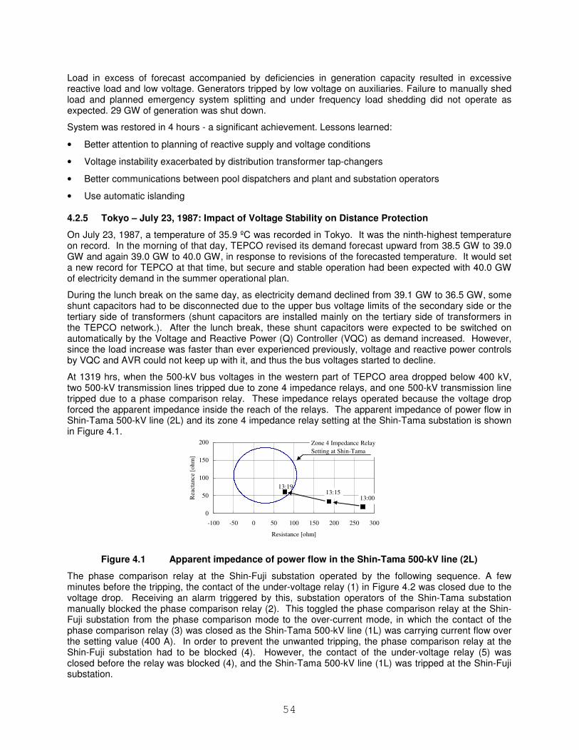
54
Load in excess of forecast accompanied by deficiencies in generation capacity resulted in excessive reactive load and low voltage. Generators tripped by low voltage on auxiliaries. Failure to manually shed load and planned emergency system splitting and under frequency load shedding did not operate as expected. 29 GW of generation was shut down.
System was restored in 4 hours - a significant achievement. Lessons learned:
• Better attention to planning of reactive supply and voltage conditions
• Voltage instability exacerbated by distribution transformer tap-changers
• Better communications between pool dispatchers and plant and substation operators
• Use automatic islanding
4.2.5 Tokyo – July 23, 1987: Impact of Voltage Stability on Distance Protection
On July 23, 1987, a temperature of 35.9 ºC was recorded in Tokyo. It was the ninth-highest temperature on record. In the morning of that day, TEPCO revised its demand forecast upward from 38.5 GW to 39.0 GW and again 39.0 GW to 40.0 GW, in response to revisions of the forecasted temperature. It would set a new record for TEPCO at that time, but secure and stable operation had been expected with 40.0 GW of electricity demand in the summer operational plan.
During the lunch break on the same day, as electricity demand declined from 39.1 GW to 36.5 GW, some shunt capacitors had to be disconnected due to the upper bus voltage limits of the secondary side or the tertiary side of transformers (shunt capacitors are installed mainly on the tertiary side of transformers in the TEPCO network.). After the lunch break, these shunt capacitors were expected to be switched on automatically by the Voltage and Reactive Power (Q) Controller (VQC) as demand increased. However, since the load increase was faster than ever experienced previously, voltage and reactive power controls by VQC and AVR could not keep up with it, and thus the bus voltages started to decline.
At 1319 hrs, when the 500-kV bus voltages in the western part of TEPCO area dropped below 400 kV, two 500-kV transmission lines tripped due to zone 4 impedance relays, and one 500-kV transmission line tripped due to a phase comparison relay. These impedance relays operated because the voltage drop forced the apparent impedance inside the reach of the relays. The apparent impedance of power flow in Shin-Tama 500-kV line (2L) and its zone 4 impedance relay setting at the Shin-Tama substation is shown in Figure 4.1.
0
50
100
150
200
-100 -50 0 50 100 150 200 250 300
Resistance [ohm]
Rea
ctan
ce
[oh
m]
13:0013:15
13:19
Zone 4 Impedance Relay
Setting at Shin-Tama
Figure 4.1 Apparent impedance of power flow in the Shin-Tama 500-kV line (2L)
The phase comparison relay at the Shin-Fuji substation operated by the following sequence. A few minutes before the tripping, the contact of the under-voltage relay (1) in Figure 4.2 was closed due to the voltage drop. Receiving an alarm triggered by this, substation operators of the Shin-Tama substation manually blocked the phase comparison relay (2). This toggled the phase comparison relay at the Shin-Fuji substation from the phase comparison mode to the over-current mode, in which the contact of the phase comparison relay (3) was closed as the Shin-Tama 500-kV line (1L) was carrying current flow over the setting value (400 A). In order to prevent the unwanted tripping, the phase comparison relay at the Shin-Fuji substation had to be blocked (4). However, the contact of the under-voltage relay (5) was closed before the relay was blocked (4), and the Shin-Tama 500-kV line (1L) was tripped at the Shin-Fuji substation.
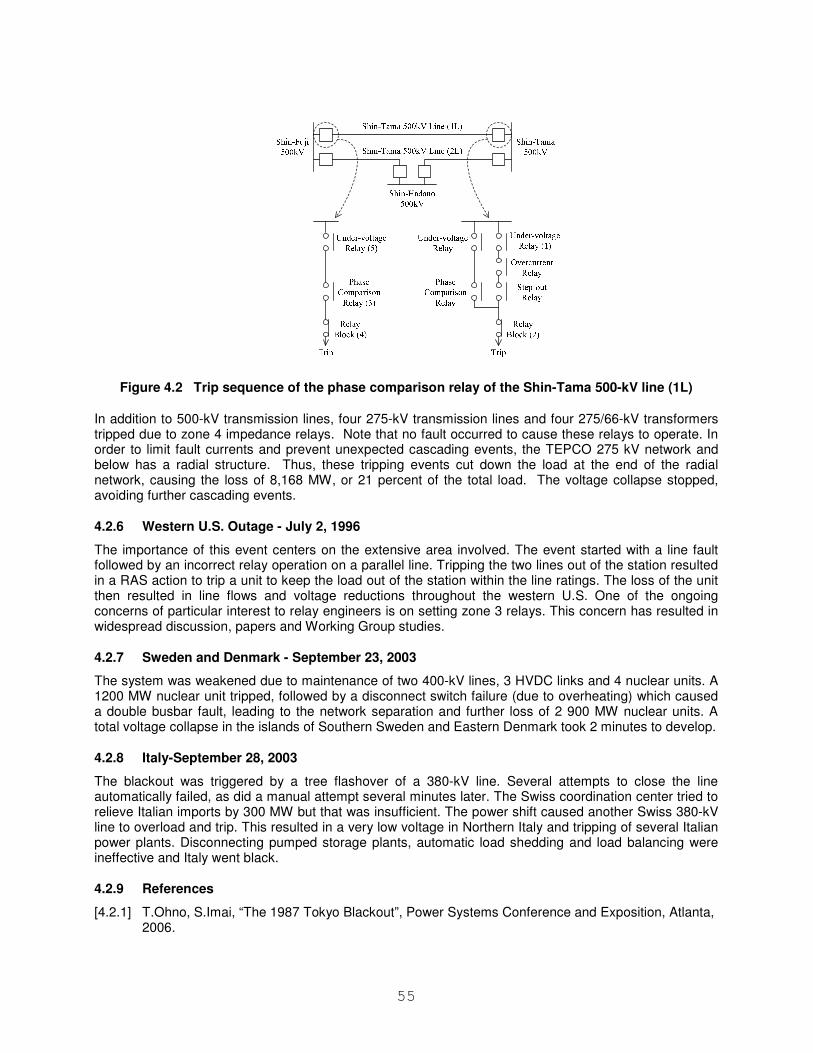
55
Figure 4.2 Trip sequence of the phase comparison relay of the Shin-Tama 500-kV line (1L)
In addition to 500-kV transmission lines, four 275-kV transmission lines and four 275/66-kV transformers tripped due to zone 4 impedance relays. Note that no fault occurred to cause these relays to operate. In order to limit fault currents and prevent unexpected cascading events, the TEPCO 275 kV network and below has a radial structure. Thus, these tripping events cut down the load at the end of the radial network, causing the loss of 8,168 MW, or 21 percent of the total load. The voltage collapse stopped, avoiding further cascading events.
4.2.6 Western U.S. Outage - July 2, 1996
The importance of this event centers on the extensive area involved. The event started with a line fault followed by an incorrect relay operation on a parallel line. Tripping the two lines out of the station resulted in a RAS action to trip a unit to keep the load out of the station within the line ratings. The loss of the unit then resulted in line flows and voltage reductions throughout the western U.S. One of the ongoing concerns of particular interest to relay engineers is on setting zone 3 relays. This concern has resulted in widespread discussion, papers and Working Group studies.
4.2.7 Sweden and Denmark - September 23, 2003
The system was weakened due to maintenance of two 400-kV lines, 3 HVDC links and 4 nuclear units. A 1200 MW nuclear unit tripped, followed by a disconnect switch failure (due to overheating) which caused a double busbar fault, leading to the network separation and further loss of 2 900 MW nuclear units. A total voltage collapse in the islands of Southern Sweden and Eastern Denmark took 2 minutes to develop.
4.2.8 Italy-September 28, 2003
The blackout was triggered by a tree flashover of a 380-kV line. Several attempts to close the line automatically failed, as did a manual attempt several minutes later. The Swiss coordination center tried to relieve Italian imports by 300 MW but that was insufficient. The power shift caused another Swiss 380-kV line to overload and trip. This resulted in a very low voltage in Northern Italy and tripping of several Italian power plants. Disconnecting pumped storage plants, automatic load shedding and load balancing were ineffective and Italy went black.
4.2.9 References
[4.2.1] T.Ohno, S.Imai, “The 1987 Tokyo Blackout”, Power Systems Conference and Exposition, Atlanta, 2006.
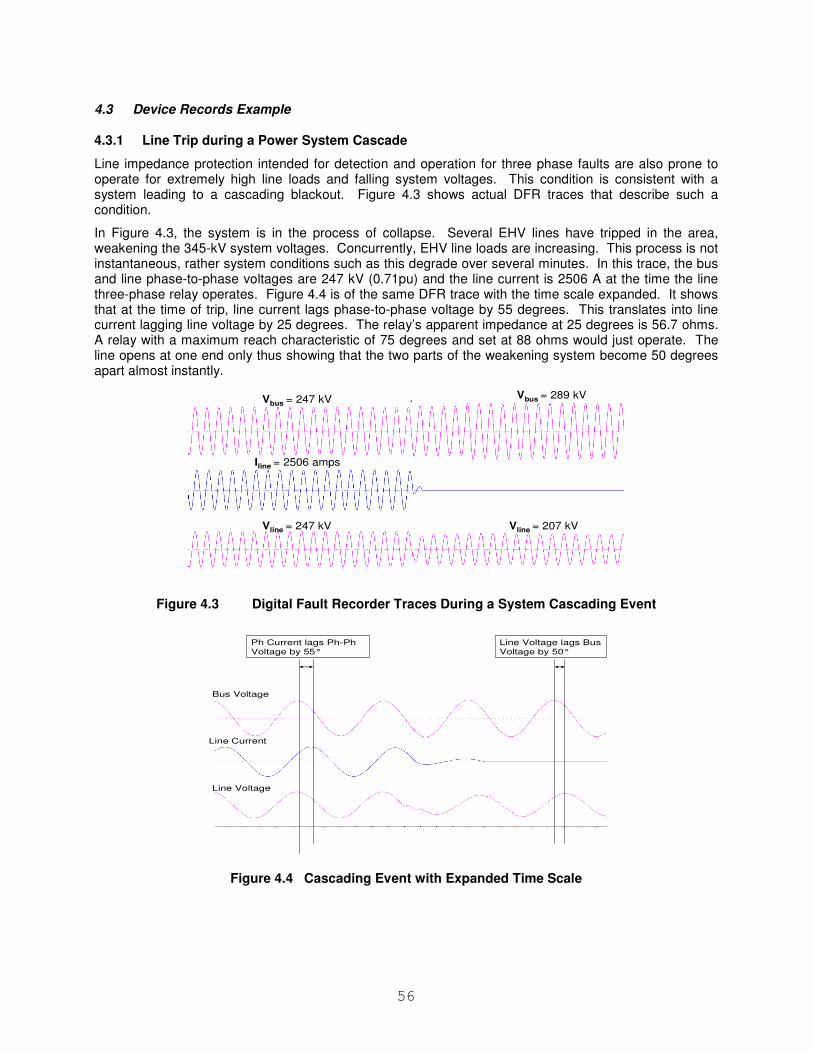
56
4.3 Device Records Example
4.3.1 Line Trip during a Power System Cascade
Line impedance protection intended for detection and operation for three phase faults are also prone to operate for extremely high line loads and falling system voltages. This condition is consistent with a system leading to a cascading blackout. Figure 4.3 shows actual DFR traces that describe such a condition.
In Figure 4.3, the system is in the process of collapse. Several EHV lines have tripped in the area, weakening the 345-kV system voltages. Concurrently, EHV line loads are increasing. This process is not instantaneous, rather system conditions such as this degrade over several minutes. In this trace, the bus and line phase-to-phase voltages are 247 kV (0.71pu) and the line current is 2506 A at the time the line three-phase relay operates. Figure 4.4 is of the same DFR trace with the time scale expanded. It shows that at the time of trip, line current lags phase-to-phase voltage by 55 degrees. This translates into line current lagging line voltage by 25 degrees. The relay’s apparent impedance at 25 degrees is 56.7 ohms. A relay with a maximum reach characteristic of 75 degrees and set at 88 ohms would just operate. The line opens at one end only thus showing that the two parts of the weakening system become 50 degrees apart almost instantly.
Vbus = 247 kV Vbus = 289 kV
Vline = 247 kV Vline = 207 kV
Iline = 2506 amps
Figure 4.3 Digital Fault Recorder Traces During a System Cascading Event
Ph Current lags Ph-Ph Voltage by 55°
Line Voltage lags Bus Voltage by 50°
Bus Voltage
Line Voltage
Line Current
Figure 4.4 Cascading Event with Expanded Time Scale
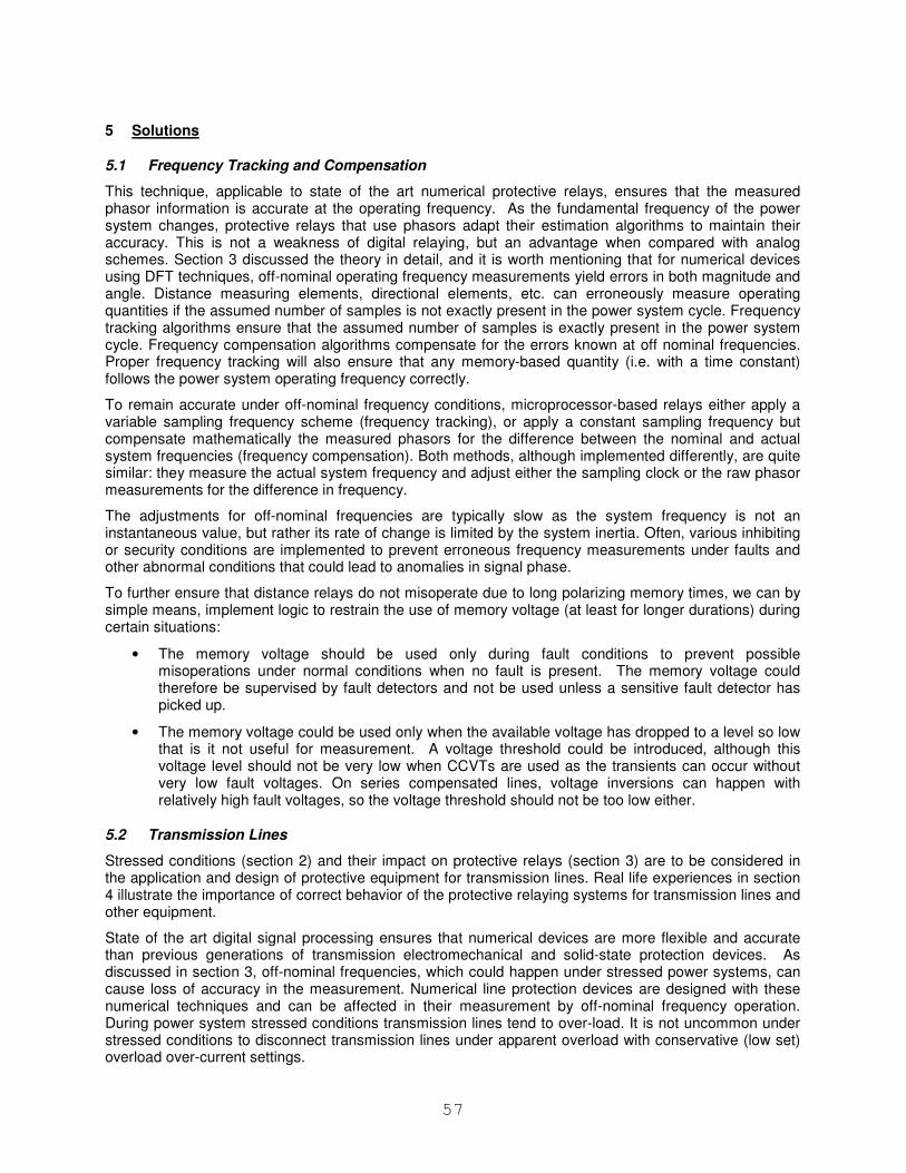
57
5 Solutions
5.1 Frequency Tracking and Compensation
This technique, applicable to state of the art numerical protective relays, ensures that the measured phasor information is accurate at the operating frequency. As the fundamental frequency of the power system changes, protective relays that use phasors adapt their estimation algorithms to maintain their accuracy. This is not a weakness of digital relaying, but an advantage when compared with analog schemes. Section 3 discussed the theory in detail, and it is worth mentioning that for numerical devices using DFT techniques, off-nominal operating frequency measurements yield errors in both magnitude and angle. Distance measuring elements, directional elements, etc. can erroneously measure operating quantities if the assumed number of samples is not exactly present in the power system cycle. Frequency tracking algorithms ensure that the assumed number of samples is exactly present in the power system cycle. Frequency compensation algorithms compensate for the errors known at off nominal frequencies. Proper frequency tracking will also ensure that any memory-based quantity (i.e. with a time constant) follows the power system operating frequency correctly.
To remain accurate under off-nominal frequency conditions, microprocessor-based relays either apply a variable sampling frequency scheme (frequency tracking), or apply a constant sampling frequency but compensate mathematically the measured phasors for the difference between the nominal and actual system frequencies (frequency compensation). Both methods, although implemented differently, are quite similar: they measure the actual system frequency and adjust either the sampling clock or the raw phasor measurements for the difference in frequency.
The adjustments for off-nominal frequencies are typically slow as the system frequency is not an instantaneous value, but rather its rate of change is limited by the system inertia. Often, various inhibiting or security conditions are implemented to prevent erroneous frequency measurements under faults and other abnormal conditions that could lead to anomalies in signal phase.
To further ensure that distance relays do not misoperate due to long polarizing memory times, we can by simple means, implement logic to restrain the use of memory voltage (at least for longer durations) during certain situations:
• The memory voltage should be used only during fault conditions to prevent possible misoperations under normal conditions when no fault is present. The memory voltage could therefore be supervised by fault detectors and not be used unless a sensitive fault detector has picked up.
• The memory voltage could be used only when the available voltage has dropped to a level so low that is it not useful for measurement. A voltage threshold could be introduced, although this voltage level should not be very low when CCVTs are used as the transients can occur without very low fault voltages. On series compensated lines, voltage inversions can happen with relatively high fault voltages, so the voltage threshold should not be too low either.
5.2 Transmission Lines
Stressed conditions (section 2) and their impact on protective relays (section 3) are to be considered in the application and design of protective equipment for transmission lines. Real life experiences in section 4 illustrate the importance of correct behavior of the protective relaying systems for transmission lines and other equipment.
State of the art digital signal processing ensures that numerical devices are more flexible and accurate than previous generations of transmission electromechanical and solid-state protection devices. As discussed in section 3, off-nominal frequencies, which could happen under stressed power systems, can cause loss of accuracy in the measurement. Numerical line protection devices are designed with these numerical techniques and can be affected in their measurement by off-nominal frequency operation. During power system stressed conditions transmission lines tend to over-load. It is not uncommon under stressed conditions to disconnect transmission lines under apparent overload with conservative (low set) overload over-current settings.
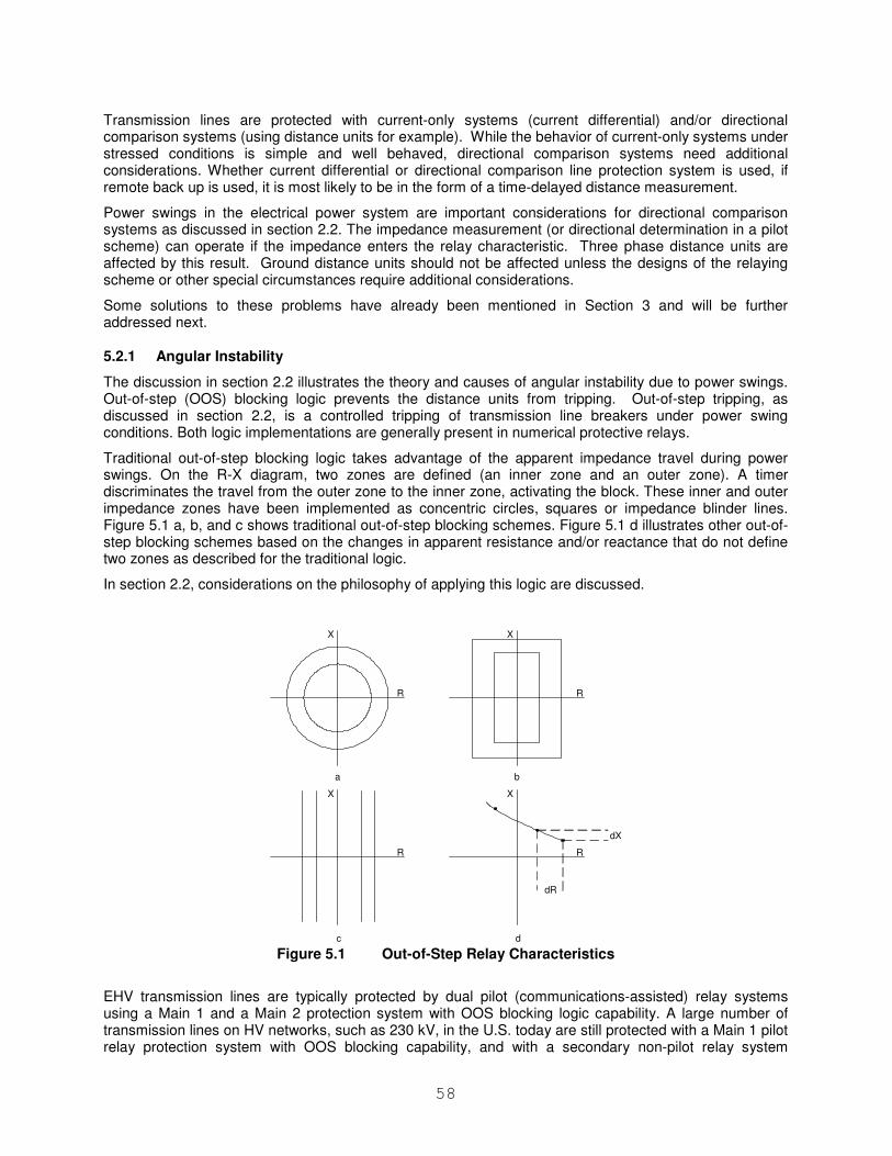
58
Transmission lines are protected with current-only systems (current differential) and/or directional comparison systems (using distance units for example). While the behavior of current-only systems under stressed conditions is simple and well behaved, directional comparison systems need additional considerations. Whether current differential or directional comparison line protection system is used, if remote back up is used, it is most likely to be in the form of a time-delayed distance measurement.
Power swings in the electrical power system are important considerations for directional comparison systems as discussed in section 2.2. The impedance measurement (or directional determination in a pilot scheme) can operate if the impedance enters the relay characteristic. Three phase distance units are affected by this result. Ground distance units should not be affected unless the designs of the relaying scheme or other special circumstances require additional considerations.
Some solutions to these problems have already been mentioned in Section 3 and will be further addressed next.
5.2.1 Angular Instability
The discussion in section 2.2 illustrates the theory and causes of angular instability due to power swings. Out-of-step (OOS) blocking logic prevents the distance units from tripping. Out-of-step tripping, as discussed in section 2.2, is a controlled tripping of transmission line breakers under power swing conditions. Both logic implementations are generally present in numerical protective relays.
Traditional out-of-step blocking logic takes advantage of the apparent impedance travel during power swings. On the R-X diagram, two zones are defined (an inner zone and an outer zone). A timer discriminates the travel from the outer zone to the inner zone, activating the block. These inner and outer impedance zones have been implemented as concentric circles, squares or impedance blinder lines. Figure 5.1 a, b, and c shows traditional out-of-step blocking schemes. Figure 5.1 d illustrates other out-of-step blocking schemes based on the changes in apparent resistance and/or reactance that do not define two zones as described for the traditional logic.
In section 2.2, considerations on the philosophy of applying this logic are discussed.
R
X
a
R
X
b
R
X
c
R
X
d
dR
dX
Figure 5.1 Out-of-Step Relay Characteristics
EHV transmission lines are typically protected by dual pilot (communications-assisted) relay systems using a Main 1 and a Main 2 protection system with OOS blocking logic capability. A large number of transmission lines on HV networks, such as 230 kV, in the U.S. today are still protected with a Main 1 pilot relay protection system with OOS blocking capability, and with a secondary non-pilot relay system
59
consisting of phase distance and directional over-current relays that most likely do not have OOS blocking detection logic. Such secondary non-pilot relay systems could operate during stable and unstable OOS conditions by Zone 1 distance and instantaneous directional over-current elements.
During the last 20 years, many Zone 1 distance relays operated during power-swings and out-of-step conditions and removed transmission lines from service at undesired network location [2.3.6]. Therefore, in critical HV lines the application of two pilot protection relay systems, for instance a Main 1 and a Main 2, with similar functionality and with OOS blocking and tripping capability should be used, just as on EHV systems.
In addition, single-pole tripping increases the stability of the power system by minimizing the impact to the power system after it is disturbed by single-line-to-ground faults. Single-phase-to-ground faults occurring during OOS conditions could cause the un-faulted phase impedance trajectories to enter the Zone 2 and Zone 1 distance relay characteristics as the angle δ between machines approaches 180 degrees To ensure that the power system can be separated in a controlled manner and balanced regional operations can be achieved during system OOS, it is important that the distance relays retain the single-pole tripping capability during system OOS conditions.
Power swings present a challenge to relay and scheme designers. If distance functions are completely blocked in response to the power swing, an unblocking mechanism may need to be provided. Alternatively, distance functions may not be blocked but altered in a way that allows maintaining security while providing for some limited dependability. Additionally, schemes not susceptible to power swings may be used permanently or upon detecting power swings to maintain dependability. Following are examples of such advanced applications.
5.2.1.1 Unblocking schemes
Under power swing conditions the apparent impedance keeps traveling at the rate dictated by the period of the swing. Under fault conditions, the apparent impedance in the faulted loop shifts to the fault position and stops traveling further. This is the base for a class of power swing blocking/unblocking schemes. These schemes work as follows: a rapid progression of the impedance or an equivalent parameter from the load to fault region signifies a fault; a slower constant progression signifies a swing; a subsequent rapid change and/or lack of further movement signify a fault during the ongoing power swing.
These schemes may be challenged by very slow power swings. A fault occurring at the top of the current envelope/bottom of the voltage envelope may cause no visible changes in the relay signals. The unblocking action is then initiated from the criterion of lack of further movement. However, if the movement is slow to begin with, the distinction becomes difficult. Moreover, the locus travels slowest when it crosses the line impedance.
These schemes cannot distinguish internal from external faults, and need extra intelligence, as described below, to provide more dependability.
5.2.1.2 Application of narrow quadrilateral functions
During unstable power swings the impedance locus crosses the line impedance vector. If a narrow quadrilateral characteristic is used as depicted in Figure 5.2-a below, the locus will spend a finite time within the characteristic. The narrow width of the characteristic limits the time the function stays picked up when the locus flies through the characteristics. A simple time delay is used to ride through this condition. A legitimate fault would move the locus onto the characteristic, and stop it there (Figure 5.2-b). Using a directional comparison scheme based on such time-delayed quadrilateral functions ensures more selectivity when covering the entire line (Figure 5.1-c).
During power swings the concept of memory polarization does not apply. The cross-polarization faces issues, as the healthy phases rotate constantly during a fault combined with an unstable swing. Therefore, a self-polarized distance function faces dependability problems for close-in faults. One solution is to apply non-directional zones as in Figure 5.2-d to ensure dependability at the expense of potential minor loss of directional integrity for close in reverse faults.
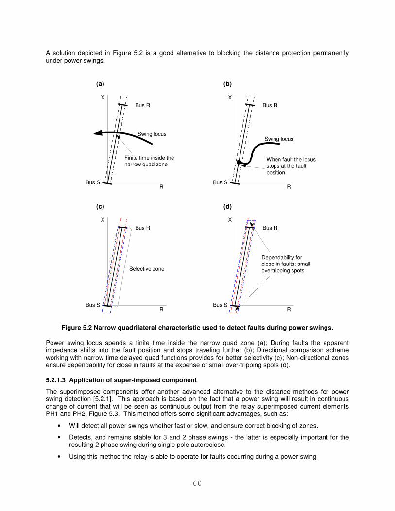
60
A solution depicted in Figure 5.2 is a good alternative to blocking the distance protection permanently under power swings.
Bus R
Bus S
Swing locus
X
R
(a)
Finite time inside the
narrow quad zone
Bus R
Bus S
Swing locus
X
R
(b)
When fault the locus
stops at the fault
position
Bus R
Bus S
X
R
(c)
Selective zone
Bus R
Bus S
X
R
(d)
Dependability for
close in faults; small
overtripping spots
Figure 5.2 Narrow quadrilateral characteristic used to detect faults during power swings.
Power swing locus spends a finite time inside the narrow quad zone (a); During faults the apparent impedance shifts into the fault position and stops traveling further (b); Directional comparison scheme working with narrow time-delayed quad functions provides for better selectivity (c); Non-directional zones ensure dependability for close in faults at the expense of small over-tripping spots (d).
5.2.1.3 Application of super-imposed component
The superimposed components offer another advanced alternative to the distance methods for power swing detection [5.2.1]. This approach is based on the fact that a power swing will result in continuous change of current that will be seen as continuous output from the relay superimposed current elements PH1 and PH2, Figure 5.3. This method offers some significant advantages, such as:
• Will detect all power swings whether fast or slow, and ensure correct blocking of zones.
• Detects, and remains stable for 3 and 2 phase swings - the latter is especially important for the resulting 2 phase swing during single pole autoreclose.
• Using this method the relay is able to operate for faults occurring during a power swing
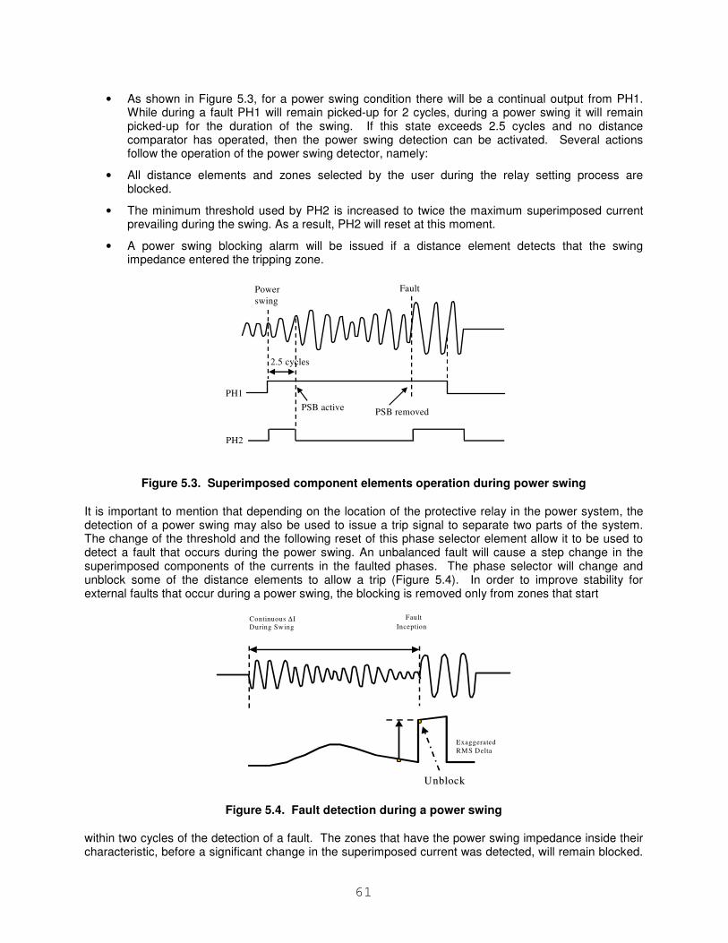
61
• As shown in Figure 5.3, for a power swing condition there will be a continual output from PH1. While during a fault PH1 will remain picked-up for 2 cycles, during a power swing it will remain picked-up for the duration of the swing. If this state exceeds 2.5 cycles and no distance comparator has operated, then the power swing detection can be activated. Several actions follow the operation of the power swing detector, namely:
• All distance elements and zones selected by the user during the relay setting process are blocked.
• The minimum threshold used by PH2 is increased to twice the maximum superimposed current prevailing during the swing. As a result, PH2 will reset at this moment.
• A power swing blocking alarm will be issued if a distance element detects that the swing impedance entered the tripping zone.
Power
swing
Fault
PH1
PH2
PSB activePSB removed
2.5 cycles
Figure 5.3. Superimposed component elements operation during power swing
It is important to mention that depending on the location of the protective relay in the power system, the detection of a power swing may also be used to issue a trip signal to separate two parts of the system. The change of the threshold and the following reset of this phase selector element allow it to be used to detect a fault that occurs during the power swing. An unbalanced fault will cause a step change in the superimposed components of the currents in the faulted phases. The phase selector will change and unblock some of the distance elements to allow a trip (Figure 5.4). In order to improve stability for external faults that occur during a power swing, the blocking is removed only from zones that start
Continuous ∆ I
During Swing
Fault
Inception
Exaggerated
RM S Delta
UnblockUnblock
Figure 5.4. Fault detection during a power swing
within two cycles of the detection of a fault. The zones that have the power swing impedance inside their characteristic, before a significant change in the superimposed current was detected, will remain blocked.
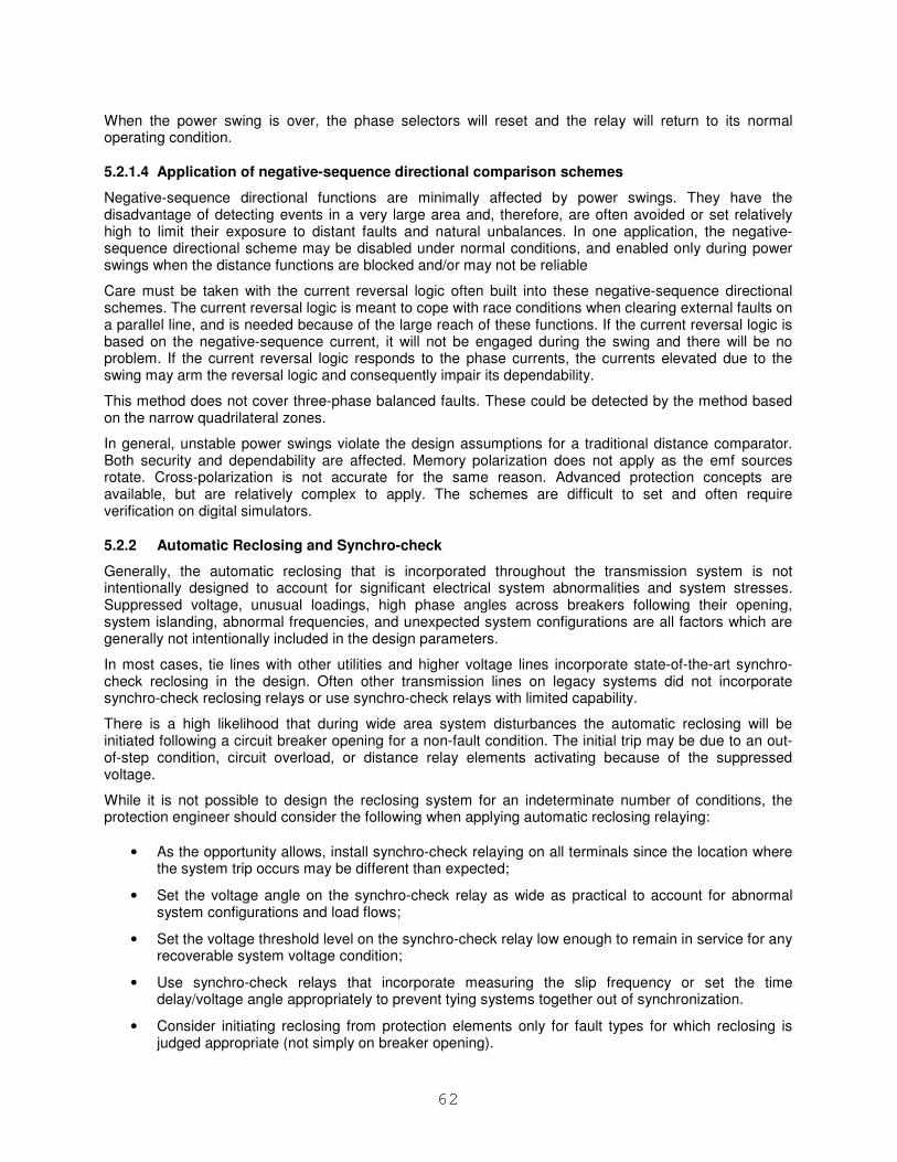
62
When the power swing is over, the phase selectors will reset and the relay will return to its normal operating condition.
5.2.1.4 Application of negative-sequence directional comparison schemes
Negative-sequence directional functions are minimally affected by power swings. They have the disadvantage of detecting events in a very large area and, therefore, are often avoided or set relatively high to limit their exposure to distant faults and natural unbalances. In one application, the negative-sequence directional scheme may be disabled under normal conditions, and enabled only during power swings when the distance functions are blocked and/or may not be reliable
Care must be taken with the current reversal logic often built into these negative-sequence directional schemes. The current reversal logic is meant to cope with race conditions when clearing external faults on a parallel line, and is needed because of the large reach of these functions. If the current reversal logic is based on the negative-sequence current, it will not be engaged during the swing and there will be no problem. If the current reversal logic responds to the phase currents, the currents elevated due to the swing may arm the reversal logic and consequently impair its dependability.
This method does not cover three-phase balanced faults. These could be detected by the method based on the narrow quadrilateral zones.
In general, unstable power swings violate the design assumptions for a traditional distance comparator. Both security and dependability are affected. Memory polarization does not apply as the emf sources rotate. Cross-polarization is not accurate for the same reason. Advanced protection concepts are available, but are relatively complex to apply. The schemes are difficult to set and often require verification on digital simulators.
5.2.2 Automatic Reclosing and Synchro-check
Generally, the automatic reclosing that is incorporated throughout the transmission system is not intentionally designed to account for significant electrical system abnormalities and system stresses. Suppressed voltage, unusual loadings, high phase angles across breakers following their opening, system islanding, abnormal frequencies, and unexpected system configurations are all factors which are generally not intentionally included in the design parameters.
In most cases, tie lines with other utilities and higher voltage lines incorporate state-of-the-art synchro-check reclosing in the design. Often other transmission lines on legacy systems did not incorporate synchro-check reclosing relays or use synchro-check relays with limited capability.
There is a high likelihood that during wide area system disturbances the automatic reclosing will be initiated following a circuit breaker opening for a non-fault condition. The initial trip may be due to an out-of-step condition, circuit overload, or distance relay elements activating because of the suppressed voltage.
While it is not possible to design the reclosing system for an indeterminate number of conditions, the protection engineer should consider the following when applying automatic reclosing relaying:
• As the opportunity allows, install synchro-check relaying on all terminals since the location where the system trip occurs may be different than expected;
• Set the voltage angle on the synchro-check relay as wide as practical to account for abnormal system configurations and load flows;
• Set the voltage threshold level on the synchro-check relay low enough to remain in service for any recoverable system voltage condition;
• Use synchro-check relays that incorporate measuring the slip frequency or set the time delay/voltage angle appropriately to prevent tying systems together out of synchronization.
• Consider initiating reclosing from protection elements only for fault types for which reclosing is judged appropriate (not simply on breaker opening).
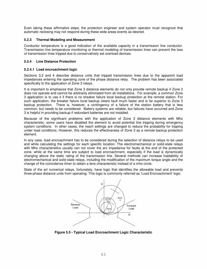
63
Even taking these affirmative steps, the protection engineer and system operator must recognize that automatic reclosing may not respond during these wide areas events as desired.
5.2.3 Thermal Modeling and Measurement
Conductor temperature is a good indication of the available capacity in a transmission line conductor. Transmission line temperature monitoring or thermal modeling of transmission lines can prevent the loss of transmission lines tripped due to conservatively set overload devices.
5.2.4 Line Distance Protection
5.2.4.1 Load encroachment logic
Sections 3.2 and 4 describe distance units that tripped transmission lines due to the apparent load impedances entering the operating zone of the phase distance relay. The problem has been associated specifically to the application of Zone 3 relays.
It is important to emphasize that Zone 3 distance elements do not only provide remote backup if Zone 2 does not operate and cannot be arbitrarily eliminated from all installations. For example, a common Zone 3 application is to use it if there is no breaker failure local backup protection at the remote station. For such application, the breaker failure local backup clears fault much faster and is far superior to Zone 3 backup protection. There is, however, a contingency of a failure of the station battery that is less common, but needs to be considered. Battery systems are reliable, but failures have occurred and Zone 3 is helpful in providing backup if redundant batteries are not installed.
Because of the significant problems with the application of Zone 3 distance elements with Mho characteristic, some users have disabled the element to avoid potential line tripping during emergency system conditions. In other cases, the reach settings are changed to reduce the probability for tripping under load conditions. However, this reduces the effectiveness of Zone 3 as a remote backup protection element.
In any case, load encroachment has to be considered during the selection of distance relays to be used and while calculating the settings for each specific location. The electromechanical or solid-state relays with Mho characteristics usually can not cover the arc impedance for faults at the end of the protected zone, while at the same time are subject to load encroachment, especially if the load is dynamically changing above the static rating of the transmission line. Several methods can increase loadability of electromechanical and solid state relays, including the modification of the maximum torque angle and the change of the coincidence timer to obtain a lens characteristic instead of a mho circle.
State of the art numerical relays, fortunately, have logic that identifies the allowable load and prevents three-phase distance units from operating. This logic is commonly referred as ‘Load Encroachment’ logic.
R
X
Zone1
Zone2
Zone3
Reverse
LoadForward
Load
Figure 5.5 - Typical Load Encroachment Logic Characteristic
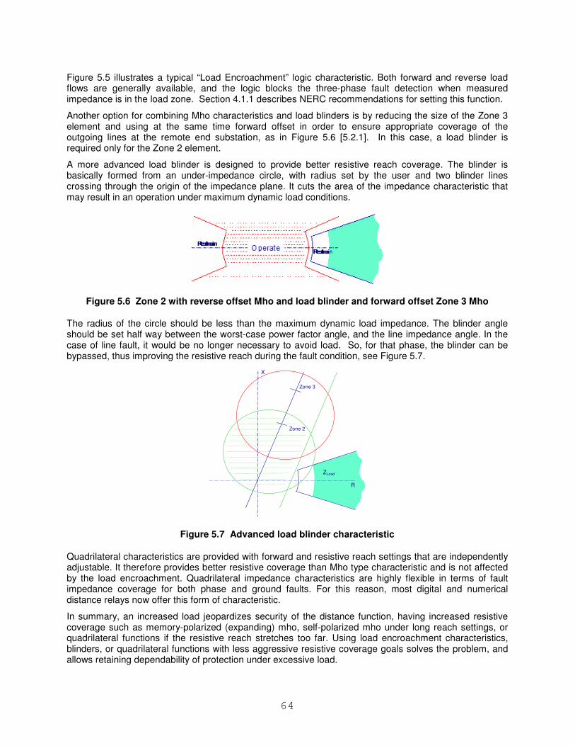
64
Figure 5.5 illustrates a typical “Load Encroachment” logic characteristic. Both forward and reverse load flows are generally available, and the logic blocks the three-phase fault detection when measured impedance is in the load zone. Section 4.1.1 describes NERC recommendations for setting this function.
Another option for combining Mho characteristics and load blinders is by reducing the size of the Zone 3 element and using at the same time forward offset in order to ensure appropriate coverage of the outgoing lines at the remote end substation, as in Figure 5.6 [5.2.1]. In this case, a load blinder is required only for the Zone 2 element.
A more advanced load blinder is designed to provide better resistive reach coverage. The blinder is basically formed from an under-impedance circle, with radius set by the user and two blinder lines crossing through the origin of the impedance plane. It cuts the area of the impedance characteristic that may result in an operation under maximum dynamic load conditions.
Figure 5.6 Zone 2 with reverse offset Mho and load blinder and forward offset Zone 3 Mho
The radius of the circle should be less than the maximum dynamic load impedance. The blinder angle should be set half way between the worst-case power factor angle, and the line impedance angle. In the case of line fault, it would be no longer necessary to avoid load. So, for that phase, the blinder can be bypassed, thus improving the resistive reach during the fault condition, see Figure 5.7.
X
Zone 2
Zone 3
R
ZLoad
Figure 5.7 Advanced load blinder characteristic
Quadrilateral characteristics are provided with forward and resistive reach settings that are independently adjustable. It therefore provides better resistive coverage than Mho type characteristic and is not affected by the load encroachment. Quadrilateral impedance characteristics are highly flexible in terms of fault impedance coverage for both phase and ground faults. For this reason, most digital and numerical distance relays now offer this form of characteristic.
In summary, an increased load jeopardizes security of the distance function, having increased resistive coverage such as memory-polarized (expanding) mho, self-polarized mho under long reach settings, or quadrilateral functions if the resistive reach stretches too far. Using load encroachment characteristics, blinders, or quadrilateral functions with less aggressive resistive coverage goals solves the problem, and allows retaining dependability of protection under excessive load.
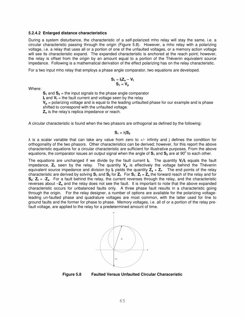
65
5.2.4.2 Enlarged distance characteristics
During a system disturbance, the characteristic of a self-polarized mho relay will stay the same, i.e. a circular characteristic passing through the origin (Figure 5.8). However, a mho relay with a polarizing voltage, i.e. a relay that uses all or a portion of one of the unfaulted voltages, or a memory action voltage will see its characteristic expand. The expanded characteristic is anchored at the reach point; however, the relay is offset from the origin by an amount equal to a portion of the Thévenin equivalent source impedance. Following is a mathematical derivation of the effect polarizing has on the relay characteristic.
For a two input mho relay that employs a phase angle comparator, two equations are developed.
S1 = IfZn – Vf S2 = Vp
Where: S1 and S2 = the input signals to the phase angle comparator If and Vf = the fault current and voltage seen by the relay Vp = polarizing voltage and is equal to the leading unfaulted phase for our example and is phase shifted to correspond with the unfaulted voltage. Zn is the relay’s replica impedance or reach.
A circular characteristic is found when the two phasors are orthogonal as defined by the following:
S1 = λjS2
λ is a scalar variable that can take any value from zero to +/- infinity and j defines the condition for orthogonality of the two phasors. Other characteristics can be derived; however, for this report the above characteristic equations for a circular characteristic are sufficient for illustrative purposes. From the above equations, the comparator issues an output signal when the angle of S1 and S2 are at 90
o to each other.
The equations are unchanged if we divide by the fault current If. The quantity Vf/If equals the fault impedance, Zf, seen by the relay. The quantity Vp is effectively the voltage behind the Thévenin equivalent source impedance and division by If yields the quantity Zs + Zf. The end points of the relay characteristic are derived by solving S1 and S2 for Zf. For S1: Zf = Zn the forward reach of the relay and for S2: Zf = -Zs. For a fault behind the relay, the current reverses through the relay, and the characteristic reverses about –Zs and the relay does not see the fault. It is important to note that the above expanded characteristic occurs for unbalanced faults only. A three phase fault results in a characteristic going through the origin. For the relay designer, a number of options are available for the polarizing voltage- leading un-faulted phase and quadrature voltages are most common, with the latter used for line to ground faults and the former for phase to phase. Memory voltages, i.e. all of or a portion of the relay pre-fault voltage, are applied to the relay for a predetermined amount of time.
-Zs
Zn
R
jX
Figure 5.8 Faulted Versus Unfaulted Circular Characeristic
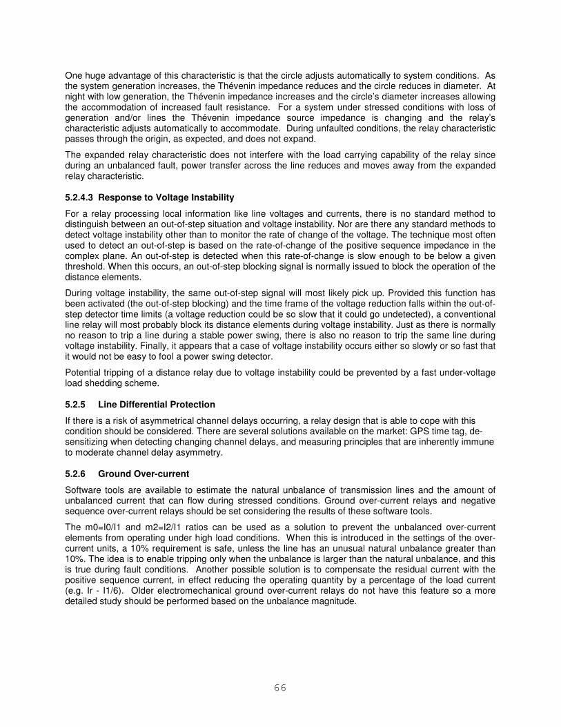
66
One huge advantage of this characteristic is that the circle adjusts automatically to system conditions. As the system generation increases, the Thévenin impedance reduces and the circle reduces in diameter. At night with low generation, the Thévenin impedance increases and the circle’s diameter increases allowing the accommodation of increased fault resistance. For a system under stressed conditions with loss of generation and/or lines the Thévenin impedance source impedance is changing and the relay’s characteristic adjusts automatically to accommodate. During unfaulted conditions, the relay characteristic passes through the origin, as expected, and does not expand.
The expanded relay characteristic does not interfere with the load carrying capability of the relay since during an unbalanced fault, power transfer across the line reduces and moves away from the expanded relay characteristic.
5.2.4.3 Response to Voltage Instability
For a relay processing local information like line voltages and currents, there is no standard method to distinguish between an out-of-step situation and voltage instability. Nor are there any standard methods to detect voltage instability other than to monitor the rate of change of the voltage. The technique most often used to detect an out-of-step is based on the rate-of-change of the positive sequence impedance in the complex plane. An out-of-step is detected when this rate-of-change is slow enough to be below a given threshold. When this occurs, an out-of-step blocking signal is normally issued to block the operation of the distance elements.
During voltage instability, the same out-of-step signal will most likely pick up. Provided this function has been activated (the out-of-step blocking) and the time frame of the voltage reduction falls within the out-of-step detector time limits (a voltage reduction could be so slow that it could go undetected), a conventional line relay will most probably block its distance elements during voltage instability. Just as there is normally no reason to trip a line during a stable power swing, there is also no reason to trip the same line during voltage instability. Finally, it appears that a case of voltage instability occurs either so slowly or so fast that it would not be easy to fool a power swing detector.
Potential tripping of a distance relay due to voltage instability could be prevented by a fast under-voltage load shedding scheme.
5.2.5 Line Differential Protection
If there is a risk of asymmetrical channel delays occurring, a relay design that is able to cope with this condition should be considered. There are several solutions available on the market: GPS time tag, de-sensitizing when detecting changing channel delays, and measuring principles that are inherently immune to moderate channel delay asymmetry.
5.2.6 Ground Over-current
Software tools are available to estimate the natural unbalance of transmission lines and the amount of unbalanced current that can flow during stressed conditions. Ground over-current relays and negative sequence over-current relays should be set considering the results of these software tools.
The m0=I0/I1 and m2=I2/I1 ratios can be used as a solution to prevent the unbalanced over-current elements from operating under high load conditions. When this is introduced in the settings of the over-current units, a 10% requirement is safe, unless the line has an unusual natural unbalance greater than 10%. The idea is to enable tripping only when the unbalance is larger than the natural unbalance, and this is true during fault conditions. Another possible solution is to compensate the residual current with the positive sequence current, in effect reducing the operating quantity by a percentage of the load current (e.g. Ir - I1/6). Older electromechanical ground over-current relays do not have this feature so a more detailed study should be performed based on the unbalance magnitude.
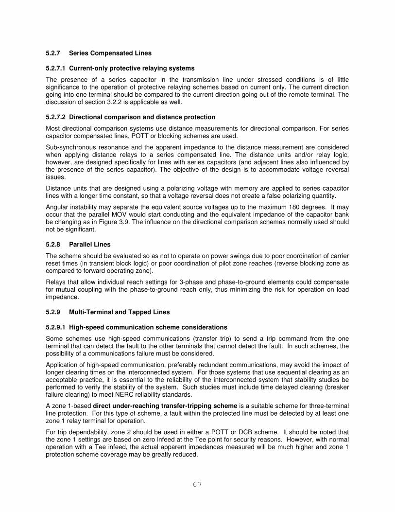
67
5.2.7 Series Compensated Lines
5.2.7.1 Current-only protective relaying systems
The presence of a series capacitor in the transmission line under stressed conditions is of little significance to the operation of protective relaying schemes based on current only. The current direction going into one terminal should be compared to the current direction going out of the remote terminal. The discussion of section 3.2.2 is applicable as well.
5.2.7.2 Directional comparison and distance protection
Most directional comparison systems use distance measurements for directional comparison. For series capacitor compensated lines, POTT or blocking schemes are used.
Sub-synchronous resonance and the apparent impedance to the distance measurement are considered when applying distance relays to a series compensated line. The distance units and/or relay logic, however, are designed specifically for lines with series capacitors (and adjacent lines also influenced by the presence of the series capacitor). The objective of the design is to accommodate voltage reversal issues.
Distance units that are designed using a polarizing voltage with memory are applied to series capacitor lines with a longer time constant, so that a voltage reversal does not create a false polarizing quantity.
Angular instability may separate the equivalent source voltages up to the maximum 180 degrees. It may occur that the parallel MOV would start conducting and the equivalent impedance of the capacitor bank be changing as in Figure 3.9. The influence on the directional comparison schemes normally used should not be significant.
5.2.8 Parallel Lines
The scheme should be evaluated so as not to operate on power swings due to poor coordination of carrier reset times (in transient block logic) or poor coordination of pilot zone reaches (reverse blocking zone as compared to forward operating zone).
Relays that allow individual reach settings for 3-phase and phase-to-ground elements could compensate for mutual coupling with the phase-to-ground reach only, thus minimizing the risk for operation on load impedance.
5.2.9 Multi-Terminal and Tapped Lines
5.2.9.1 High-speed communication scheme considerations
Some schemes use high-speed communications (transfer trip) to send a trip command from the one terminal that can detect the fault to the other terminals that cannot detect the fault. In such schemes, the possibility of a communications failure must be considered.
Application of high-speed communication, preferably redundant communications, may avoid the impact of longer clearing times on the interconnected system. For those systems that use sequential clearing as an acceptable practice, it is essential to the reliability of the interconnected system that stability studies be performed to verify the stability of the system. Such studies must include time delayed clearing (breaker failure clearing) to meet NERC reliability standards.
A zone 1-based direct under-reaching transfer-tripping scheme is a suitable scheme for three-terminal line protection. For this type of scheme, a fault within the protected line must be detected by at least one zone 1 relay terminal for operation.
For trip dependability, zone 2 should be used in either a POTT or DCB scheme. It should be noted that the zone 1 settings are based on zero infeed at the Tee point for security reasons. However, with normal operation with a Tee infeed, the actual apparent impedances measured will be much higher and zone 1 protection scheme coverage may be greatly reduced.
68
A permissive overreaching scheme is very secure; requiring all three terminals to detect the fault before tripping can be initiated at any given terminal. Tripping requires the local overreaching zone 2 distance element operation and receipt of a permissive trip signal from the two remote terminals. For this scheme to operate successfully, the reach of the permissive zone 2 elements must be set to detect all line faults for all infeed conditions. The zone 2 permissive setting is generally set for 125% of the maximum apparent impedance as measured from each terminal.
A modified (standard in most modern relays) POTT scheme that is commonly applied is one where if the breaker is open, the relays echo back permission to high-speed trip to the other terminals. In addition, if the terminal is very weak and does not detect a fault when a permissive signal is received, the relay can be programmed to echo back permission to trip to the stronger terminals that see the fault. Both of these schemes allow high-speed tripping of all terminals on the line.
For some three-terminal applications, where the infeed factor is several multiples of the actual line impedance, it may not be possible to set the zone 2 permissive elements.
Typically, that is due to the following reasons:
• The required zone 2 reach may not meet the line loadability requirements, and may impose more restrictive line loading limits.
• The larger zone 2 settings may not coordinate with adjacent lines due to their extended reach, unless the zone 2 tripping times are increased to provide the coordination.
• The zone 2 unconditional timed tripping elements, if used, may reach through tapped step down transformers and must coordinate for low voltage faults.
• The zone 2 relays could trip for stable power swings.
For such cases, an alternative scheme will be required.
Similar to the permissive scheme, high-speed tripping is achieved at all terminals if the zone 2 overreaching protection elements are set to detect all line faults for all infeed conditions. It is subject to the same protection issues as the permissive scheme discussed above. However, directional blocking has an advantage over a permissive scheme when system changes over time alter the infeed error ratio, preventing one of the terminals from seeing a fault. Under such conditions a permissive scheme would not be able to high-speed trip at any terminal, but the directional blocking scheme will trip, albeit sequentially (discussed below), making it less dependent on the source impedances.
Directional blocking with sequential tripping schemes accept that at least one terminal must open before the relays at the remaining terminals can detect the fault, and that no blocking elements operate. Once the first terminal is open (removing the infeed effect), the other two terminals become able to detect the fault.
This scheme relies upon the operation of one of the three-terminal relays for fault clearance. For this reason, this type of scheme should be used with backup protection either local or remote. If local backup protection is used, then redundancy of relay input sources and devices are necessary, as a failure of one input source or relay will prevent one or more remote terminals from detecting the faults. Some of the concerns with sequential clearing are identified below.
The interdependency of the two terminals causes fault clearing times to double. Some of the issues associated with longer fault clearing times include, but are not limited to the following:
• Increased fault clearing times decrease or eliminate critical clearing stability margins resulting in dynamic instability.
• Remote backup clearing times may be extended or clearing time margins reduced.
• Breaker failure clearing times will increase at the sequential terminals.
• Voltage recovery post-fault can take longer due to the longer clearing times.
• Damage at the point of fault will increase.
• Transformers supplying fault current may exceed their mechanical through-fault duration curve limits.
• The longer tripping times may have a negative impact on loads.
69
Microprocessor-based protection relays and digital communications make line differential schemes more versatile. The scheme performs a differential comparison on a per-phase basis and communicates using one of several types of communication media. The current differential principle is suited to protect three-terminal lines and it does not need to contend with problems associated with voltage, loading, and swings. Moreover, with current differential relays at each terminal, there is no infeed error. Phase-comparison relay schemes share many of the advantages of line current differential. Under normal operation, with all communications channels in service, each relay receives two remote current waveform samples and makes its local tripping decision based on a comparison with its locally acquired samples. A local trip decision also causes a transfer trip to be sent to the two remote terminals. If one of the three bidirectional communications paths is interrupted, two of the three remaining relays will still be able to receive remote samples from the other two and is still capable of making a local tripping decision and sending a transfer trip.
Current differential protection systems are very dependant on a functioning communication channel at all terminals of the line, and the loss of this channel may prevent high-speed clearing of faults. If high speed clearing of faults is needed for stability, the application of protection system redundancy should be considered. The current differential system should be backed up by a pilot system or a second communication channel.
5.2.9.2 Decrease in line loadability
The settings typically required to provide protection coverage of a three-terminal line, where fault infeed is experienced, will be much larger than the setting necessary without the third terminal. This setting can reach many multiples of the actual impedance of the protected line, resulting in a decrease of the line loadability unless some form of load blinder or encroachment logic is applied.
The larger operating characteristic reduces the line loadability, as the line protection must not trip according to the following NERC loadability requirement: 1.5 times the maximum current line rating at 85% nominal voltage and a load power factor angle of 30 degrees.
It should be noted that three-terminal lines must meet the NERC requirements. A technical exception is provided for lines that can not meet this requirement, which places trip dependability over line loading, thus allowing for the line rating to be reduced, to meet the criteria. NERC’s technical paper Methods to Increase Line Relay Loadability, provides methods to increase loadability of protective relaying functions by augmenting, repositioning, and reshaping, mho element impedance relays without decreasing protection coverage.
5.2.9.3 High-speed scheme security including power swing issues
On multi-terminal lines, the Zone 2 protection zone reaches are generally set farther and over-current settings are made more sensitive to cover infeed considerations. This results in reaches much farther beyond remote line terminals than zone 2 relays set on two terminal lines. Thus, these relays will see more external faults and blocking schemes are more prone to false tripping for communication failures.
Due to the need for extended zone 2 coverage to accommodate the apparent impedance, it is possible that stable power swings may encroach into the relay phase characteristics. While susceptibility to tripping during power swings is typically thought of as a concern for zone 1 protection where tripping occurs without intentional time delay, tripping during power swings has been observed for zone 2 and zone 3 relays providing non-conditional time delayed tripping as well as zone 2 relays operating in communication-assisted protection schemes.
The exposure to operation of relays providing non-conditional time delayed tripping is significantly increased when relay reaches are extended to account for infeed effects on three-terminal lines or infeed effects associated with providing remote backup protection. The increased size of the relay operating characteristic increases the amount of time that an apparent impedance swing will remain inside the relay characteristic.
Communication assisted protection schemes are also more susceptible to misoperation during system swings when relay reaches are increased to account for infeed effects. During typical system loading conditions the security of communication assisted protection schemes is improved relative to non-
70
conditional tripping relays because all line terminals must see the fault within the protected zone in order to initiate tripping. During system swings however, it is possible for the apparent impedance to appear within the protected zone at all terminals, resulting in a protection operation. As relay reaches are increased the likelihood that the apparent impedance will fall within the relay characteristic also is increased.
Direct Under-reaching Transfer Trip (DUTT) schemes have limited susceptibility since the tripping relays do not overreach the end of the line and the zone 1 relay reaches are not increased to account for infeed effects. Permissive Overreaching Transfer Trip (POTT) and Directional Comparison Blocking (DCB) schemes do have increased susceptibility on multi-terminal lines since the tripping relay reach must be increased to account for infeed effects. The susceptibility for misoperation of POTT schemes is limited to swings for which the apparent impedance is inside the protected zone at all relay terminals. The susceptibility for misoperation is greatest for DCB schemes since the apparent impedance could be seen as outside the reach of the carrier trip relay at one or more relay terminals, but also outside the reach of the carrier blocking relays at all terminals.
Appendix A describes the issues presented by these equations and examples.
5.2.10 References [5.2.1] V. Madani, D. Novosel, A. Apostolov, S. Corsi,:” Innovative Solutions for Preventing Wide Area
Disturbance Propagation,” IREP Symposium for Bulk Power Systems Dynamics and Control VI, Cortina d’Ampezzo, Italy, August 2004.
5.3 Transformer Protection
Supervisory control action based on the transformer loading, top oil temperature and the winding temperature would provide a reliable alternative to tripping by relays sensitive to overloads. It is important to set temperature limits on the top oil and the winding temperatures to prevent severe damage to the transformer. Over-current relays used as back up to primary differential relays could be replaced by a second set of differential relays to provide redundancy.
Modern transformer monitoring devices provide additional information such as time to reach the maximum permissible temperature based on present loading and also the loss of transformer life due to overload. These could be used to assist operators in the decision process.
Solutions to off-nominal frequency conditions using frequency compensation and tracking are described in section 5.1.
5.4 Generator Protection
Protective devices applied for generator protection may trip during a system disturbance. It is important that these relays be applied properly so that they protect the generator, but help preserve the system integrity by not tripping unnecessarily during a disturbance. Reference [3.4.1] reports on generator relay operations during some major system events and provides solutions for relay applications. This section describes the gist of these solutions.
5.4.1 Abnormal Voltage Protection
Abnormal voltage protection for generators should coordinate with any external control systems regulating the system voltage. During voltage transients, the generator excitation control devices may allow short-term operation of the generator and excitation system outside their rated safety limit. Therefore, generator excitation protection devices must coordinate with the excitation control devices for pick up levels as well as time delays to avoid unexpected tripping of the generator during system disturbances. These settings may drift over a period of time (for non-microprocessor relays) to negate the theoretical coordination margins. Periodic testing may be used to ensure reliable operation.
71
5.4.2 System Phase Backup
Settings should limit the reach of these relays and coordinate with overload conditions. Implementation of redundant line relaying, breaker failure including direct transfer trip to remote line terminals, and bus protection limits the need to extend the operation zone of these relays and they can be set to provide backup protection only for faults up to the switchyard. Note that you may still have to set the relays to detect faults at the remote end of the line, if the high-voltage bus is of a ring or a breaker-and-a-half configuration. However, the generator backup relay settings will not be as sensitive, since you do not have to take into consideration the infeed from the other sources on the high-voltage bus. The operation of the ground backup over-current relays in generator step-up neutrals should also be reviewed to ensure that they will not trip the generator unnecessarily.
For larger units, a distance relay type 21 is preferred with VTs connected to the generator terminal and CTs to the generator neutral side. It is often applied with no offset so that the location of the generator VTs lies on the mho characteristic circle. In theory, the reach is set to cover the longest line out of the station including the effects of infeed. This, however, is not always an achievable setting. The reach setting must remain conservatively above the machine rating to prevent inadvertent trips on generator swings and severe voltage disturbances. It is suggested that the distance relay should be set to carry at least 200% of the generator rating at rated power factor. A long reach setting should be checked for coordination with auxiliary bus time over-current relays and must allow for the generator response to short time system overloads or recoverable generator swings.
For smaller units, the voltage-controlled over-current 51V-C or voltage-restrained over-current relay 51V-R is sufficient. For voltage controlled 51V-C type relays, the over-current pickup is typically set below generator nameplate current. The control voltage setting should be below the lowest credible voltage the power system may operate at. Choosing too high a voltage may allow an undesired operation of the relay during wide-area disturbances.
5.4.3 Under-frequency
The first line of defense against under-frequency conditions is an automatic load shedding scheme, which should operate first to keep the power system frequency from continuously falling. Thus, it is required that the automatic load shedding scheme should be coordinated with the generators’ own under-frequency protection. If, however, the automatic load shedding program is not able to restore the system frequency in time, generators must be tripped for their own equipment protection even before the automatic load shedding is completed. If the system frequency restoration effort by automatic load shedding is proven to be insufficient, then the installation of additional load shedding programs should be considered to compensate the generators that may trip early.
The application of under-frequency protection on hydroelectric units is not normally required, as hydro units are able to withstand wide frequency variations without having their turbines damaged. Hydro units not equipped with under-frequency protection are likely to survive during the system disturbance and remain connected to the grid. Those surviving hydro units could play a major role in the speedy restoration of the power system. Consideration may be given to applying this protection to hydro generators, if it is required to preserve station service during a system collapse, since some power plant auxiliaries may not function properly at reduced frequency.
Due to the reduced capability of auxiliary motor drives and shaft driven loads, especially in steam plants, if the frequency falls by 2 Hz or more, power station auxiliaries can trip out. For 60 Hz systems, studies have shown that the plant capability will begin to decrease at 57 Hz and the frequencies in the region of 53-55 Hz are critical for continued plant operation due to the reduction in output of pumps.
5.4.4 Loss of Field (LOF)
Since a LOF relay can trip on a recoverable transient swing that may enter its operating zone, the LOF relay should be carefully set. Different power swing scenarios should be run to find out how long a stable power swing locus is likely to remain in the LOF operating zone. Initially leading generator power factors, slow/no voltage regulator response, low system impedance, and close-in three-phase faults cleared almost at critical clearing time are factors contributing to the worst stable swing conditions. The time delay
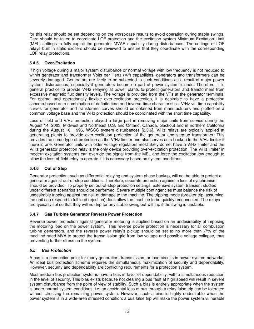
72
for this relay should be set depending on the worst-case results to avoid operation during stable swings. Care should be taken to coordinate LOF protection and the excitation system Minimum Excitation Limit (MEL) settings to fully exploit the generator MVAR capability during disturbances. The settings of LOF relays built in static exciters should be reviewed to ensure that they coordinate with the corresponding LOF relay protections.
5.4.5 Over-Excitation
If high voltage during a major system disturbance or normal voltage with low frequency is not reduced to within generator and transformer Volts per Hertz (V/f) capabilities, generators and transformers can be severely damaged. Generators are likely to be subjected to such conditions as a result of major power system disturbances, especially if generators become a part of power system islands. Therefore, it is general practice to provide V/Hz relaying at power plants to protect generators and transformers from excessive magnetic flux density levels. The voltage is provided from the VTs at the generator terminals. For optimal and operationally flexible over-excitation protection, it is desirable to have a protection scheme based on a combination of definite time and inverse-time characteristics. V/Hz vs. time capability curves for generator and transformer curves should be obtained from manufacturers and plotted on a common voltage base and the V/Hz protection should be coordinated with the short time capability.
Loss of field and V/Hz protection played a large part in removing major units from service during the August 14, 2003, Midwest and Northeast U.S. and Ontario, Canada, blackout and in northern California during the August 10, 1996, WSCC system disturbances [2.3.6]. V/Hz relays are typically applied at generating plants to provide over-excitation protection of the generator and step-up transformer. This provides the same type of protection as the V/Hz limiter and also serves as a backup to the V/Hz limiter if there is one. Generator units with older voltage regulators most likely do not have a V/Hz limiter and the V/Hz generator protection relay is the only device providing over-excitation protection. The V/Hz limiter in modern excitation systems can override the signal from the MEL and force the excitation low enough to allow the loss-of-field relay to operate if it is necessary based on system conditions.
5.4.6 Out of Step
Generator protection, such as differential relaying and system phase backup, will not be able to protect a generator against out-of-step conditions. Therefore, separate protection against a loss of synchronism should be provided. To properly set out-of-step protection settings, extensive system transient studies under different scenarios should be performed. Severe multiple contingencies must balance the risk of undesirable tripping against the risk of damage to the machine. The tripping mode (breaker trip, assuming the unit can respond to full load rejection) does allow the machine to be quickly reconnected. The relays are typically set so that they will not trip for any stable swing but will trip if the swing is unstable.
5.4.7 Gas Turbine Generator Reverse Power Protection
Reverse power protection against generator motoring is applied based on an undesirability of imposing the motoring load on the power system. This reverse power protection is necessary for all combustion turbine generators, and the reverse power relay’s pickup should be set to no more than -7% of the machine rated MVA to protect the transmission grid from low voltage and possible voltage collapse, thus preventing further stress on the system.
5.5 Bus Protection
A bus is a connection point for many generation, transmission, or load circuits in power system networks. An ideal bus protection scheme requires the simultaneous maximization of security and dependability. However, security and dependability are conflicting requirements for a protection system.
Most modern bus protection systems have a bias in favor of dependability, with a simultaneous reduction in the level of security. This bias exists because not clearing a bus fault at high speed will result in severe system disturbance from the point of view of stability. Such a bias is entirely appropriate when the system is under normal system conditions, i.e. an accidental loss of bus through a relay false trip can be tolerated without stressing the remaining power system. However, such a bias is highly undesirable when the power system is in a wide-area stressed condition: a bus false trip will make the power system vulnerable
73
to cascading failures. Under these circumstances, an adaptive bus protection scheme is suggested in Figure 5.9 [5.5.1]. Upon detection at the system control center that the power system is wide-area stressed, a signal would be sent to key bus protection facilities consisting of sample based percentage differential relaying, phasor based percentage differential relaying, and directional comparison, to change their tripping logic from the ‘or’ function to an ‘and’ or to a ‘2 out of 3 voting’ logic [see Section 5.10.1 for an explanation of a voting logic]. Thus one would exchange a loss in dependability by accepting some risk that a fault may not be cleared, with an increased assurance that only genuine faults would lead to a trip, and thus the possibility of false trips would be reduced during wide-area stressed conditions. The details of operating principles of phasor based percentage differential relaying, sample based percentage differential relaying, and directional comparison for bus protection, respectively, are contained in [5.5.2].
Figure 5.9 Adaptive control of dependability and security of bus protection systems
5.5.1 References
[5.5.1] A.G. Phadke, “Hidden Failures in Protection Systems”, Bulk Power System Dynamics and Control V, Aug., 2001, Onomichi, Japan.
[5.5.2] A.G. Phadke, J. S. Thorp, “Computer Relaying for Power Systems”, Research Studies Press LTD, 1988.
5.6 Shunt Reactor/Capacitor Protection
Unbalanced systems and harmonics during stressed conditions can adversely affect shunt capacitor protection and control. System unbalance can be obviated by using protection that compensates for system unbalance or by using a differential scheme. Relays with good filtering and signal processing can greatly improve the response of the protection scheme to harmonics. Severe harmonic content may best be addressed by power quality monitoring. The monitoring should alarm to alert system operators of the condition. The operators could then decide to make system configuration changes such as restoring some lines or switching on or off cap banks that could alleviate the condition.
5.7 Feeder Protection
Cold load pickup is important for restoration following a major disturbance. However, de-sensitizing the feeder relay has to take into account the risk of a cable deteriorating due to voltage swells caused by the system disturbance.
74
5.8 Motor Protection
IEEE “Guide for AC Motor Protection” [3.7.1] provides information on impacts of abnormal power supply to motors and possible solutions. The abnormal supply would be a system of a major system disturbance.
According to NEMA MG1 – Motors and Generators Standard generally an AC motor will operate acceptably within its limits under normal running conditions at its rated load with voltage variation up to ± 10 % of rated voltage, or ± 5 % of rated frequency, or a combination of the sum of the absolute values of both deviations not exceeding 10 % as long as the frequency variation does not exceed ± 5 %. A synchronous motor has an additional condition that rated excitation current needs to be maintained.
5.9 Under-frequency Load Shedding Protection
Under-frequency load shedding plans are based on studies of a system’s dynamic performance, given the greatest probable imbalance between load and generation. Plans should be coordinated between interconnected power systems as well as with under-frequency isolation of generating units, tripping of shunt capacitors, and other automatic actions which occur in the system under abnormal frequency, voltage, or power flow conditions [3.9.1]. Issues addressed in section 3.9 should be considered in designing an optimal load shedding plan.
Improvements that could be achieved by implementing adaptive settings based on actual system conditions will be discussed next. Power system load shedding by under-frequency relays is a quick, simple, and reliable strategy, but has several disadvantages, such as shedding load when the frequency is already low and the amount of load shed may not be optimal. Implementation of the rate-of-change of frequency is an immediate indicator of the power unbalance; however, an oscillatory nature of the rate-of-change of frequency can make the measurement unreliable.
Improvements with adaptive load shedding enable shedding a minimal amount of load that will allow frequency to recover. This would mean that the relay settings and switching actions would adapt to the prevailing system conditions.
Firstly, the actual load assigned for shedding at each step should be periodically calculated at a central site based on the actual load distribution. The optimal load distribution may depend on how the system separates. If the separation is controlled from a central site or can be predicted, an algorithm may calculate the settings and assign the appropriate load in coordination with switching actions. Secondly, further improvements can be accomplished by considering available spinning reserve, total system inertia, dynamic performances and limits of the operating wide area frequency control system, and load characteristics. These data should be periodically determined at the central site from SCADA data and provided to the relays using low speed communications. High-speed communication may be required to and from the central location for fast-developing disturbances, such as multi-machine angular instability.
If the composite system inertia constant is known, the actual power imbalance may be calculated directly from the frequency derivative [5.2.1] [5.9.1]. This detection should be fast (to avoid a large frequency drop) and done at the location close to the center of inertia. High-speed communications are required to send a signal and initiate load shedding at appropriate locations. This method requires taking into account changes of load and generation with frequency and voltage as well as the influence of dynamic system changes on power imbalance and calculation of the average frequency derivative. In conclusion, sophisticated techniques and/or high-speed communication may be required for accurate estimation of the amount and distribution of the load to be shed.
To avoid the disadvantages of the under-frequency load shedding and difficulties with implementing the rate-of-change of frequency function, the automated load shedding that will reduce overloading or prevent system instability before the system is isolated is proposed as an advantageous strategy.
As the power system is affected by overloads, and voltage and angular instability, actions such as load shedding need to be implemented either by the operator (if there is enough time) or by implementing SIPS. If further power system degradation is still not arrested and there is an imminent danger of power system separation, this separation should be done in an adaptive way by splitting the system on a pre-planned way. This would mean that the system would be split with best possible balance between load and generation, so as to avoid shedding load in some areas and shedding generation in other areas.
75
Implementing SIPS can trigger the pre-planned separation. To assure optimal separation, separation points should be periodically evaluated and, if necessary changed, based on information and calculation at the central site based on SCADA data and provided to the relays using low speed communications.
5.9.1 References
[5.9.1] V.V. Terzija, “Adaptive Under-frequency Load Shedding Based on the Magnitude of the Disturbance Estimation”, IEEE TPRS, Vol. 21, No. 3, August 2006, Page(s): 1260- 1266.
5.10 Important Aspects of Improving Protection Performance
5.10.1 Protection scheme design
The design of protection schemes has a significant effect on the overall performance during wide area disturbances and other abnormal system conditions [1.1.1] [5.10.1] [5.10.2]. Different protection solutions offer different advantages and disadvantages that need to be considered during the protection scheme design process.
Implementing redundant schemes ensures that even if there is a failure of one relay, the fault will still be detected and cleared, thus typically satisfying the requirement for reliability and availability. Using devices with different hardware design and operating principles may further improve the reliability of the scheme, by reducing the probability of a common mode failure. In such applications, all devices operate in an OR logic scheme. However, keeping in mind that different protection functions might be susceptible to misoperation under certain abnormal conditions, if just one of the relays in the protection scheme operates inappropriately, it will result in an undesired trip of a transmission line that may lead to a further deterioration of the system disturbance.
To improve the security of the protection without sacrificing dependability, some utilities implement voting schemes. These schemes can be especially effective during stressed system conditions. Voting may be implemented using a simple combination of three parallel “legs” of series trip contacts from two relays at a time or through separate hardware (e.g. programmable logic controllers). The individual relays’ operating principles and associated schemes may use any methods appropriate for line protection (e.g. distance, POTT, DCB, differential). A voting scheme typically operates as follows:
• If all three relays call for a trip, a trip is issued.
• If two relays call for a trip, a trip is issued and an alarm is generated due to the “non-tripping” relay.
• If one relay calls for a trip, the trip is blocked and an alarm is generated to identify the “tripping” relay.
Voting schemes may include extensive self-testing of the relays and vote counting devices. Automatic scheme testing may also be included in the design and may be initiated either manually or on a specific schedule. An example of using a voting scheme for bus protection is described in section 5.5.
5.10.2 Hidden failures
In order to reduce the risk of wide area system disturbances following a fault or any other system event, it is essential that the protective relays are available and work properly. Hidden failures should therefore be detected [5.5.1]. A failure of a protection device may be caused by many different factors, including not only failure of the device itself, but also of components of the overall substation protection, control and monitoring system. Detecting hidden failures requires good understanding of the principles of operation of the protection devices, their self-checking functions and their limitations, as well as properly defined methods and procedures for their detection.
A failure of a protection device may be caused by many different factors, including not only failure of the device itself, but also of components of the overall substation protection, control and monitoring system.A failure of a protective device to operate may also result from incorrect settings. This may be caused by calculation error or by inaccurate power system model. Verification of the models used in any analysis or coordination software thus becomes very important. Comparison of the fault records from protective
76
relays with simulations of the fault in the analysis tool can be used to evaluate the accuracy of the model. Manual or automatic comparison of a setting file and the settings uploaded from the protection device can detect errors in the actual relay settings.
Relay misoperation may also be caused by failures in the analog (current and voltage) circuits of the protective device. To avoid such operation, modern protective relays are equipped with voltage and current circuit supervision schemes. The voltage transformer supervision (VTS) feature is used to detect failure of the ac voltage inputs to the relay, which may be caused by internal voltage transformer faults, overloading or faults on the interconnecting wiring to relays or fuse failure.
Other examples include human error during maintenance or VT circuit switching. Following a failure of the ac voltage input there would be a misrepresentation of the phase voltages on the power system, as measured by the relay, which may result in maloperation.
5.10.3 Human errors
From recent major events it appears that a large number of protection system failures are caused by human errors. These errors include among others:
• Wiring errors
• Inadequate designs
• Errors during maintenance
• Errors during VT switching
• Incorrect settings (e.g. use of generic set points instead of set points based on system studies)
• Use of type test results for instrument transformers as opposed to field testing
• Use of type test results from protective relay manufacturer as opposed to comprehensive system simulation testing
Implementing review and certification of the processes, as well as adequate testing procedures, can reduce the number and severity of human errors causing outages.
5.10.4 References
[5.10.1] S.H. Horowitz and A.G. Phadke, “Boosting Immunity to Blackouts,” Power & Energy Magazine, September/October 2003.
[5.10.2] V. Madani, D. Novosel, R. Cremers, and F. Koers, “Impact of Wide Area Disturbances on Protection Systems and Solutions to Arrest Disturbance Propagation”, World Energy System Conference, Turin, Italy, July 2006.

77
6 Conclusions
Protection systems are often involved in major wide area disturbances, sometimes preventing further propagation, and sometimes contributing to the spread of the perturbations. A very important lesson learned from the wide spread blackouts is that the design and operation of conventional protection and control schemes have been scrutinized. As protection systems should not contribute to cascading, by improving the protection systems currently installed, the impact of wide area disturbances can be minimized and the number of disturbances decreased. In general, a protection system should operate only for conditions for which it is designed; while preventing further disturbance propagation should be achieved by designing protection and control schemes for those disturbed conditions. However, experience has shown that some relays might have prevented further cascading by tripping on system conditions for which they were not designed.
This document identifies key stressed system conditions that affect conventional protection schemes, describes field experiences under stressed conditions, and describes proven methods and solutions to improve protection performance and minimize disturbance propagation.
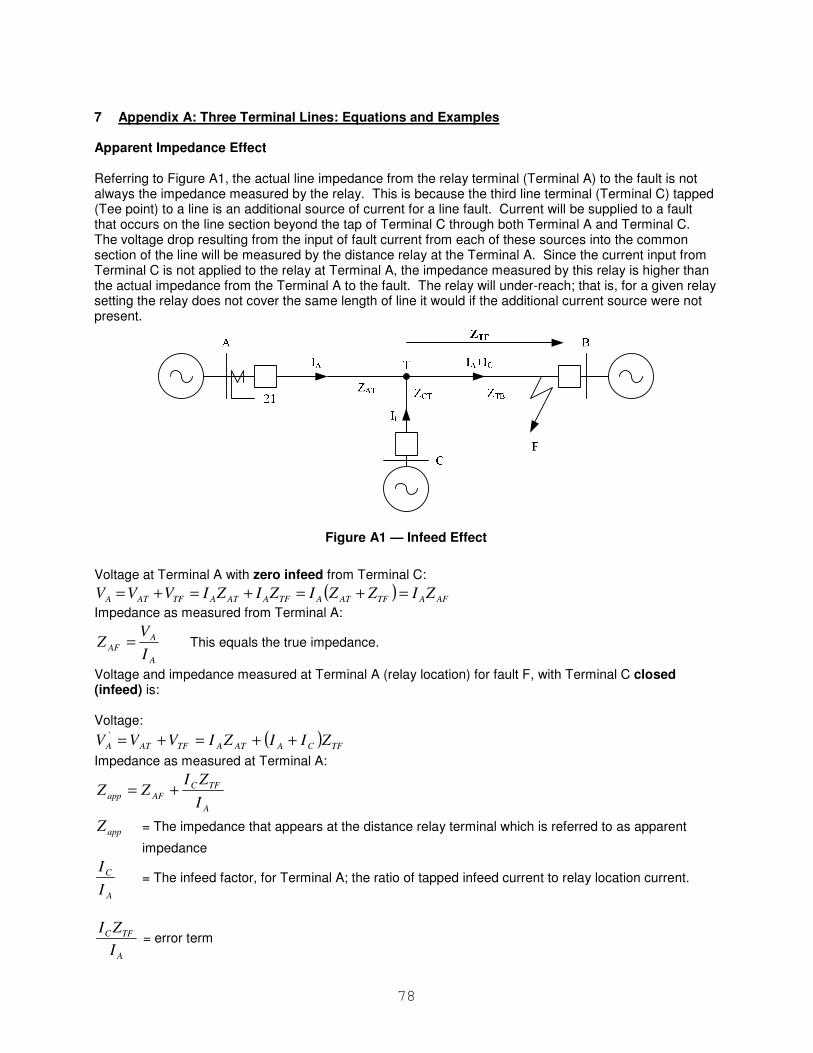
78
7 Appendix A: Three Terminal Lines: Equations and Examples Apparent Impedance Effect Referring to Figure A1, the actual line impedance from the relay terminal (Terminal A) to the fault is not always the impedance measured by the relay. This is because the third line terminal (Terminal C) tapped (Tee point) to a line is an additional source of current for a line fault. Current will be supplied to a fault that occurs on the line section beyond the tap of Terminal C through both Terminal A and Terminal C. The voltage drop resulting from the input of fault current from each of these sources into the common section of the line will be measured by the distance relay at the Terminal A. Since the current input from Terminal C is not applied to the relay at Terminal A, the impedance measured by this relay is higher than the actual impedance from the Terminal A to the fault. The relay will under-reach; that is, for a given relay setting the relay does not cover the same length of line it would if the additional current source were not present.
Figure A1 — Infeed Effect
Voltage at Terminal A with zero infeed from Terminal C:
( ) AFATFATATFAATATFATA ZIZZIZIZIVVV =+=+=+=
Impedance as measured from Terminal A:
A
A
AFI
VZ = This equals the true impedance.
Voltage and impedance measured at Terminal A (relay location) for fault F, with Terminal C closed (infeed) is: Voltage:
( ) TFCAATATFATA ZIIZIVVV ++=+='
Impedance as measured at Terminal A:
A
TFC
AFappI
ZIZZ +=
appZ = The impedance that appears at the distance relay terminal which is referred to as apparent
impedance
A
C
I
I = The infeed factor, for Terminal A; the ratio of tapped infeed current to relay location current.
A
TFC
I
ZI = error term
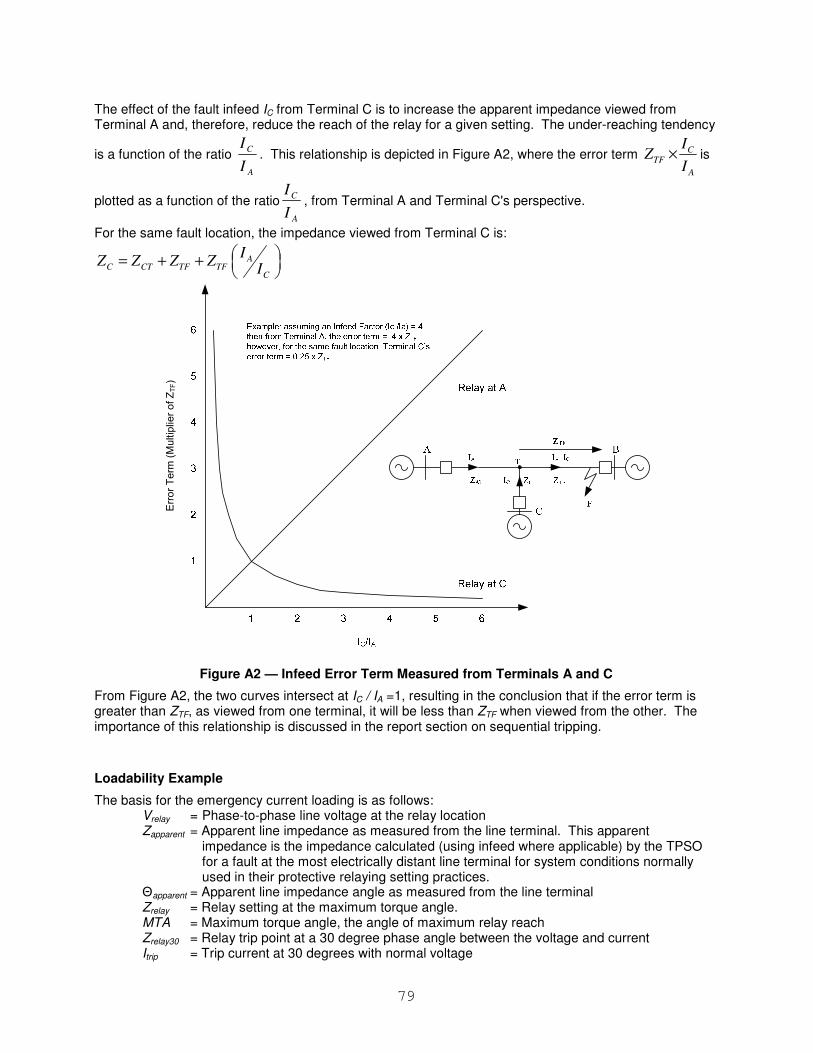
79
The effect of the fault infeed IC from Terminal C is to increase the apparent impedance viewed from Terminal A and, therefore, reduce the reach of the relay for a given setting. The under-reaching tendency
is a function of the ratio
A
C
I
I. This relationship is depicted in Figure A2, where the error term C
TF
A
IZ
I× is
plotted as a function of the ratio
A
C
I
I, from Terminal A and Terminal C's perspective.
For the same fault location, the impedance viewed from Terminal C is:
AC CT TF TF
C
IZ Z Z Z
I = + +
Figure A2 — Infeed Error Term Measured from Terminals A and C
From Figure A2, the two curves intersect at IC / IA =1, resulting in the conclusion that if the error term is greater than ZTF, as viewed from one terminal, it will be less than ZTF when viewed from the other. The importance of this relationship is discussed in the report section on sequential tripping.
Loadability Example
The basis for the emergency current loading is as follows: Vrelay = Phase-to-phase line voltage at the relay location Zapparent = Apparent line impedance as measured from the line terminal. This apparent
impedance is the impedance calculated (using infeed where applicable) by the TPSO for a fault at the most electrically distant line terminal for system conditions normally used in their protective relaying setting practices.
Θapparent = Apparent line impedance angle as measured from the line terminal Zrelay = Relay setting at the maximum torque angle. MTA = Maximum torque angle, the angle of maximum relay reach Zrelay30 = Relay trip point at a 30 degree phase angle between the voltage and current Itrip = Trip current at 30 degrees with normal voltage
Error Term (Multiplier of ZTF)
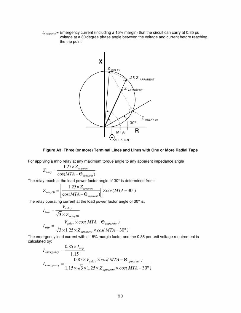
80
Iemergency = Emergency current (including a 15% margin) that the circuit can carry at 0.85 pu voltage at a 30
degree phase angle between the voltage and current before reaching
the trip point
Figure A3: Three (or more) Terminal Lines and Lines with One or More Radial Taps
For applying a mho relay at any maximum torque angle to any apparent impedance angle
)cos(
25.1
apparent
apparent
relayMTA
ZZ
Θ−
×=
The relay reach at the load power factor angle of 30° is determined from:
)30cos()cos(
25.130 °−×
Θ−
×= MTA
MTA
ZZ
apparent
apparent
relay
The relay operating current at the load power factor angle of 30° is:
303 relay
relay
tripZ
VI
×=
)MTAcos(Z.
)MTAcos(VI
apparent
apparentrelay
trip°−×××
Θ−×=
302513
The emergency load current with a 15% margin factor and the 0.85 per unit voltage requirement is calculated by:
151
850
.
I.I
trip
emergency
×=
)MTAcos(Z..
)MTAcos(V.I
apparent
apparentrelay
emergency°−××××
Θ−××=
302513151
850
1.25 Z APPARENT
Z RELAY
MTA
X
R
Z RELAY 30
300
Z APPARENT
APPARENT
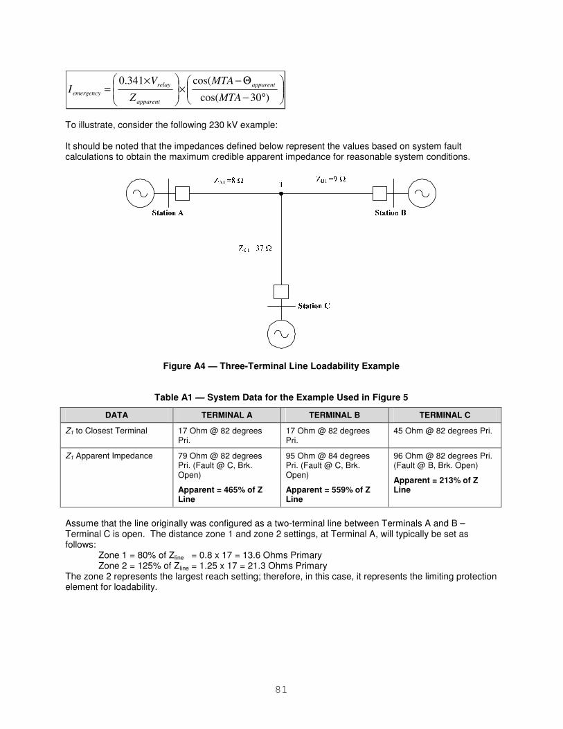
81
°−
Θ−×
×=
)30cos(
cos(341.0
MTA
MTA
Z
VI
apparent
apparent
relay
emergency
To illustrate, consider the following 230 kV example: It should be noted that the impedances defined below represent the values based on system fault calculations to obtain the maximum credible apparent impedance for reasonable system conditions.
Figure A4 — Three-Terminal Line Loadability Example
Table A1 — System Data for the Example Used in Figure 5
DATA TERMINAL A TERMINAL B TERMINAL C
Z1 to Closest Terminal 17 Ohm @ 82 degrees Pri.
17 Ohm @ 82 degrees Pri.
45 Ohm @ 82 degrees Pri.
Z1 Apparent Impedance 79 Ohm @ 82 degrees Pri. (Fault @ C, Brk. Open)
Apparent = 465% of Z Line
95 Ohm @ 84 degrees Pri. (Fault @ C, Brk. Open)
Apparent = 559% of Z Line
96 Ohm @ 82 degrees Pri. (Fault @ B, Brk. Open)
Apparent = 213% of Z Line
Assume that the line originally was configured as a two-terminal line between Terminals A and B – Terminal C is open. The distance zone 1 and zone 2 settings, at Terminal A, will typically be set as follows:
Zone 1 = 80% of Zline = 0.8 x 17 = 13.6 Ohms Primary Zone 2 = 125% of Zline = 1.25 x 17 = 21.3 Ohms Primary
The zone 2 represents the largest reach setting; therefore, in this case, it represents the limiting protection element for loadability.
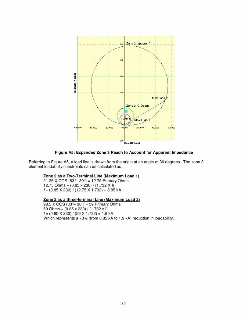
82
Figure A5: Expanded Zone 3 Reach to Account for Apparent Impedance Referring to Figure A5, a load line is drawn from the origin at an angle of 30 degrees. The zone 2 element loadability constraints can be calculated as:
Zone 2 as a Two-Terminal Line (Maximum Load 1) 21.25 X COS (83°– 30°) = 12.75 Primary Ohms 12.75 Ohms = (0.85 x 230) / (1.732 X I) I = (0.85 X 230) / (12.75 X 1.732) = 8.85 kA
Zone 2 as a three-terminal Line (Maximum Load 2) 98.5 X COS (83°– 30°) = 59 Primary Ohms 59 Ohms = (0.85 x 230) / (1.732 x I) I = (0.85 X 230) / (59 X 1.732) = 1.9 kA Which represents a 78% (from 8.85 kA to 1.9 kA) reduction in loadability.