Embed Size (px)
Citation preview
Performance of RETIMET Metal Foam Vents on Explosion-Proof Enclosures
By Lawrence W. Scott and Arthur J. Hudson
Mission: As the Nation's principal conservation agency, the Department of the Interior has respon- sibility for most of our nationally-owned public lands and natural and cultural resources. This includesfostering wise use of our land and water resources, protecting our fish and wildlife, pre- serving the environmental and cultural values of our national parks and historical places, and pro- viding for the enjoyment of life through outdoor recreation. The Department assesses our energy and mineral resources and works to assure that their development is i n the best interests of all our people. The Department also promotes the goals of the Take Pride in America campaign by encouraging stewardship and citizen responsibil- ity for the public lands and promoting citizen par- ticipation in their care. The Department also has a major responsibility.for American Indian reser- vation communities and for people who live i n Island Territories under U.S. Administration.
Report of Investigations 941 0
Performance of RETIMET Metal Foam Vents on Explosion-Proof Enclosures
By Lawrence W. Scott and Arthur J. Hudson
UNITED STATES DEPARTMENT OF THE INTERIOR Manuel Lujan, Jr., Secretary
BUREAU OF MINES T S Ary, Director
CONTENTS Page
Abstract . . . . . . . . . . . . . . . . . . . . . . . . . . . . . . . . . . . . . . . . . . . . . . . . . . . . . . . . . . . . . . . . . . . . . . . . . . . Introduction . . . . . . . . . . . . . . . . . . . . . . . . . . . . . . . . . . . . . . . . . . . . . . . . . . . . . . . . . . . . . . . . . . . . . . . . Acknowledgments . . . . . . . . . . . . . . . . . . . . . . . . . . . . . . . . . . . . . . . . . . . . . . . . . . . . . . . . . . . . . . . . . . . . Arrester material . . . . . . . . . . . . . . . . . . . . . . . . . . . . . . . . . . . . . . . . . . . . . . . . . . . . . . . . . . . . . . . . . . . . Laboratorytests . . . . . . . . . . . . . . . . . . . . . . . . . . . . . . . . . . . . . . . . . . . . . . . . . . . . . . . . . . . . . . . . . . . . .
Experimental apparatus and procedure . . . . . . . . . . . . . . . . . . . . . . . . . . . . . . . . . . . . . . . . . . . . . . . . . . Experimentalresults . . . . . . . . . . . . . . . . . . . . . . . . . . . . . . . . . . . . . . . . . . . . . . . . . . . . . . . . . . . . . . . .
Large-scaletests . . . . . . . . . . . . . . . . . . . . . . . . . . . . . . . . . . . . . . . . . . . . . . . . . . . . . . . . . . . . . . . . . . . . . Experimental apparatus and procedure . . . . . . . . . . . . . . . . . . . . . . . . . . . . . . . . . . . . . . . . . . . . . . . . . . Experimentalresults . . . . . . . . . . . . . . . . . . . . . . . . . . . . . . . . . . . . . . . . . . . . . . . . . . . . . . . . . . . . . . . .
. . . . . . . . . . . . . . . . . . . . . . . . . . . . . . . . . . . . . . . . . . . . . . . . . . . . . . . Conclusions and recommendations
ILLUSTRATIONS
1 . Prototype pressure vent . . . . . . . . . . . . . . . . . . . . . . . . . . . . . . . . . . . . . . . . . . . . . . . . . . . . . . . . . 3 2 . Schematic of test vessel . . . . . . . . . . . . . . . . . . . . . . . . . . . . . . . . . . . . . . . . . . . . . . . . . . . . . . . . . . . 4 3 . Dynamic gas-mixing system and high-speed recorder . . . . . . . . . . . . . . . . . . . . . . . . . . . . . . . . . . . . . . . 4 4 . Gaschromatograph . . . . . . . . . . . . . . . . . . . . . . . . . . . . . . . . . . . . . . . . . . . . . . . . . . . . . . . . . . . . . . . 4 5 . RETIMET metal foam material used in arrester assembly . . . . . . . . . . . . . . . . . . . . . . . . . . . . . . . . . . 5 6 . Multicompartmented variable vent area enclosure in MSHA's 500-ft3 explosion gallery in
Triadelphia, W V . . . . . . . . . . . . . . . . . . . . . . . . . . . . . . . . . . . . . . . . . . . . . . . . . . . . . . . . . . . . . . . . 6 . . . . . . 7 . Vent area enclosure showing 100-in2 vent. 36-in2 vent with protective cover open. and 64-in2 vent 7
8 . Pressure versus vent-area-to-enclosure-volume ratio using 6.8% CH,. air . . . . . . . . . . . . . . . . . . . . . . . . 7 9 . Failureof36-in2vent . . . . . . . . . . . . . . . . . . . . . . . . . . . . . . . . . . . . . . . . . . . . . . . . . . . . . . . . . . . . . . 7
. . . . . . . . . . . . . . . . . . . . . . . . . . . . . . . . . . . 10 . Pressure versus methane concentration using 150-in2 vent 8 11 . Spaced-plate heat absorber . . . . . . . . . . . . . . . . . . . . . . . . . . . . . . . . . . . . . . . . . . . . . . . . . . . . . . . . . 8 12 . Heat absorber attached to enclosure cover . . . . . . . . . . . . . . . . . . . . . . . . . . . . . . . . . . . . . . . . . . . . . . 8 13 . RETIMET metal foam after test with coal dust. oil. and grease on its external surface . . . . . . . . . . . . . . 9
TABLES
1 . Properties of grade 45 NC-13 RETIMET metal foam . . . . . . . . . . . . . . . . . . . . . . . . . . . . . . . . . . . . . . . . . . . . . . . . . . . . . . . . . . . . . . . . 2 . Summary of test results for RETIMET metal foam in 9.75% CH,. air
. . . . . . . . . . . . . . 3 . Summary of test results for RETIMET metal foam in methane-hydrogen-air mixtures . . . . . . . . . . . . . . . . . . . . . . . . . . . . . . . 4 . Test results for RETIMET metal foam at three ignition points
Library of Congress Cataloging in Publication Data:
Scott, Lawrence W. Performance of RETIMET metal foam vents on explosion-proof enclosures / by
Lawrence W. Scott and Arthur J. Hudson.
p. cm. - (Report of investigations; 9410)
Supt. of Docs. no.: I 28.23:9410.
1. Mine explosions-Prevention. 2. Foamed materials. I. Hudson,Arthur J. 11. Title. 111. Series: Report of investigations (United States. Bureau of Mines); 9410.
TN23.U43 [TN313] 622 s--dc20 [622'.82] 91-43015 CIP
gram
hertz
inch
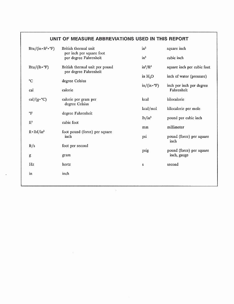
UNIT OF MEASURE ABBREVIATIONS USED IN THIS REPORT
Btu/(in* ft2*"F) British thermal unit in2 square inch per inch per square foot per degree Fahrenheit in3 cubic inch
Btu/(lbm OF) British thermal unit per pound square inch per cubic foot per degree Fahrenheit
inch of water (pressure) OC degree Celsius
inch per inch per degree cal calorie Fahrenheit
cal/(ge "C) calorie per gram per kilocalorie degree Celsius
kilocalorie per mole O F degree Fahrenheit
pound per cubic inch ft3 cubic foot
millimeter ft lbf/in2 foot pound (force) per square
inch pound (force) per square inch
ft/s foot per second pound (force) per square
g inch, gauge
H z second
in
kcal
kcal/mol
lb/in3
mm
psi
PERFORMANCE OF RETIMET METAL FOAM VENTS ON EXPLOSION-PROOF ENCLOSURES
By Lawrence W. ~ c o t t ' and Arthur J. ~ u d s o n *
ABSTRACT
The performance of RETIMET metal foam as a flame arrester on explosion-proof enclosures was investigated by the U.S. Bureau of Mines both in laboratory tests and at the U.S. Mine Safety and Health Administration's (MSHA's) Approval and Certification Center, Triadelphia, WV. The objective of this research was to develop a permissible pressure vent for use on lightweight, vented, explosion- proof enclosures. In laboratory tests, four grades of RETIMET, a stainless steel foam material, were evaluated: (1) 45 NC-7, (2) 45 NC-13, (3) 80 NC-7, and (4) 80 NC-13.
Explosive gas mixtures were prepared by a dynamic flow system. Ignition was by a low-voltage arc. Each grade of RETIMET metal foam successfully arrested the flame front in all methane-air tests.
To evaluate RETIMET metal foam on large, commercial size enclosures, a multicompartmented enclosure was designed and tested in MSHA's explosion gallery in Triadelphia, WV. Extensive explosion testing revealed that a minimum vent-area-to-enclosure-volume ratio of 11.33 in2/ft3 is required to keep internal pressure rises below 3 psig. The RETIMET metal foam functioned satisfactorily in all tests as evidenced by the absence of external ignitions.
'~lectrical engineer. 2~lectronic technician. Pittsburgh Research Center, U.S. Bureau of Mines, Pittsburgh, PA.
INTRODUCTION
A flame arrester is a device that prevents the passage of a flame from one location to another through absorp- tion of heat energy. Items commonly used as flame arrest- ers remove sufficient heat to quench the combustion front. In comparison with solid materials, gases are ordinarily quite poor heat conductors. Solid surfaces can extract substantial amounts of heat only from those portions of the gas that are close to the surface. Quenching distances represent the maximum diametrical separation of surfaces at which heat extraction by the surfaces destroys the self- propagating reaction front. Thus, flame arresters must comprise some configuration adequate to break the flame front into flamelets of quenchable size and then to quench those flamelets. To extinguish the combustion front, each flamelet must be quenched; in addition, if hot combustion gases pass through the arrester, the gases must be cooled sufficiently so that reignition does not occur beyond the arrester.
Arresters usually consist either of an aggregation of parallel small channels or a maze of small channels and are intended to offer minimal resistance to gas flow. Common types of flame arresters consist of crimped metal ribbon, wire gauze, compressed wire mesh, perforated plates, and sintered metal arresters. Some of these have fairly general application, whereas others are more specialized.
A commercially available material called RETIMET) metal foam (made by Dunlop Aviation in the United Kingdom) has been developed that has characteristics in- dicating its suitability for use as a flame arrester. This material is a metallic foam that can be made from various metals and alloys with c o ~ e c t i n g cavities, having a very high void volume. The pore sizes of the material may be varied. Such a structure mieht ~erform well as a flame " . arrester for use on explosion-proof enclosures and be used to reduce the pressure generated by an internal methane- air explosion.
Since internal pressures may exceed 100 psig, explosion- proof enclosures are characterized by heavy wall construc- tion, tight flange gaps, and numerous cover bolts. If an enclosure could be designed to vent the pressure in a safe manner, lighter and less expensive enclosures would be possible. Lightweight construction would facilitate han- dling, thus reducing associated injuries, and improve the maintenance of large enclosures that often require mechanized equipment or several workers.
Under con t ra~ t .~*~ the U.S. Bureau of Mines investi- gated numerous concepts designed to reduce the internal
-- -- -- - --
'~eference to specific products does not imply endorsement by the U.S. Bureau of Mines.
pressure generated in explosion-proof enclosures during internal methane-air explosions. From this study, it was determined that any venting mechanism must-
1. Quench both methane and coal dust flame fronts, 2. Be highly permeable to gas flow to minimize vent
size, 3. Be capable of being readily cleaned to reduce the
possibility of clogging during underground use, and 4. Have sufficient corrosion and mechanical shock
resistance to be compatible with the mine environment.
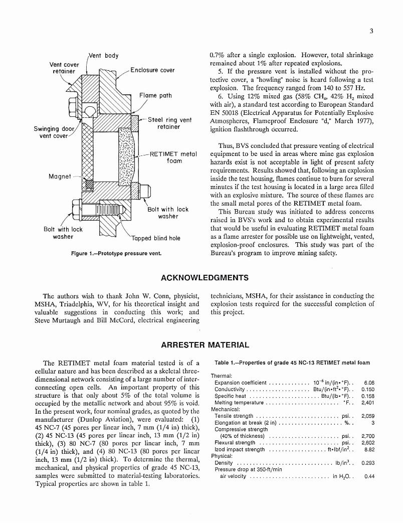
In light of these requirements, RETIMET metal foam was judged to offer the best combination of flame- arresting and mechanical properties. For a prototype vent, a 112-in-thick piece of grade 45 NC-13 RETIMET metal foam was set in a metallic frame and mounted in an en- closure cover. A cross-sectional view is shown in figure 1. The RETIMET metal foam was protected against mechan- ical damage by a hinged metal cover that swung open when the internal pressure exceeded 2 psig. Normally, this cover is held in place by a small permanent magnet.
To have a significant impact upon enclosure design, it was determined that a vent must limit internal explosion pressure to 12 psig maximum. To determine the relation- ship between vent area, pressure, and enclosure volume, a vent-area-to-enclosure-volume ratio was established through laboratory tests. Results showed that any en- closure with a vent-area-to-enclosure-volume ratio larger than 4 in2/ft3 would meet the 12-psig criterion.
To evaluate the practical application of the vent as- sembly, the Bureau entered into an informal agreement with BergbauVersuchsstrecke (BVS), Dortmund, Ger- m a n ~ . ~ The objective of this work was to determine if RETIMET metal foam could withstand repeated explo- sions without failure or extensive damage. The results of this work are summarized below:
1. The pressure vent assembly withstood explosions of 9.8% CH,-air.
2. The resistance to bending of the RETIMET metal foam was not significantly affected by the explosion.
3. An initially nonmagnetic piece of RETIMET metal foam became magnetizable through the thermal loadings of explosions.
4. The RETIMET metal foam, which previously fitted the vent structure well, underwent a shrinkage in length of
4~underman, R J. Innovations for Explosionproof Electrical En- closures (contract H0357107, Dresser Ind., Inc.). BuMines OFR 121-81, 6~mmiss ion of the European Community. Investigation on the
1980, 209 pp.; NTIS PB 82104936. Operational Safety of Housing for Electrical Equipment Which Are
S~valuation and Acceptance Criteria for Innovations in Explosion- Vented Through Large Area Flame Barriers. Rep. 7258/07/01/77, lW,
proof Electrical Enclosures (contract H0357107, Dresser Ind., Inc.). '' PP' BuMines OFR 127-83,1982,141 pp.; NTIS PB 83-233379.
0.7% after a single explosion. However, total shrinkage remained about 1% after repeated explosions.
Enclosure cover 5. If the pressure vent is installed without the pro- tective cover, a "howling" noise is heard following a test explosion. The frequency ranged from 140 to 557 Hz.
6. Using 12% mixed gas (58% CH,, 42% H, mixed with air), a standard test according to European Standard E N 50018 (Electrical Apparatus for Potentially Explosive
Steel ring vent Atmospheres, Flameproof Enclosure "d," March 1977), ignition flashthrough occurred.
Thus, BVS concluded that pressure venting of electrical tal equipment to be used in areas where mine gas explosion
hazards exist is not acceptable in light of present safety requirements. Results showed that, following an explosion inside the test housing, flames continue to burn for several minutes if the test housing is located in a large area filled with an explosive mixture. The source of these flames are the small metal pores of the RETIMET metal foam.
This Bureau study was initiated to address concerns raised in BVS's work and to obtain experimental results that would be useful in evaluating RETIMET metal foam
Tapped blind hole as a flame arrester for possible use on lightweight, vented, explosion-proof enclosures. This study was part of the
Figure 1.-Prototype pressure vent. Bureau's program to improve mining safety.
ACKNOWLEDGMENTS
The authors wish to thank John W. Conn, physicist, technicians, MSHA, for their assistance in conducting the MSHA, Triadelphia, WV, for his theoretical insight and explosion tests required for the successful completion of valuable suggestions in conducting this work; and this project. Steve Murtaugh and Bill McCord, electrical engineering
ARRESTER MATERIAL
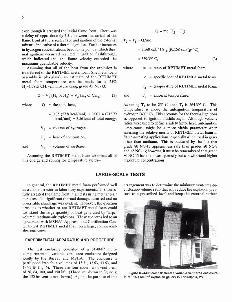
The RETIMET metal foam material tested is of a cellular nature and has been described as a skeletal three- dimensional network consisting of a large number of inter- connecting open cells. An important property of this structure is that only about 5% of the total volume is occupied by the metallic network and about 95% is void. In the present work, four nominal grades, as quoted by the manufacturer (Dunlop Aviation), were evaluated: (1) 45 NC-7 (45 pores per linear inch, 7 mm (114 in) thick), (2) 45 NC-13 (45 pores per linear inch, 13 mm (112 in) thick), (3) 80 NC-7 (80 pores per linear inch, 7 mm (114 in) thick), and (4) 80 NC-13 (80 pores per linear inch, 13 mm (112 in) thick). To determine the thermal, mechanical, and physical properties of grade 45 NC-13, samples were submitted to material-testing laboratories. Typical properties are shown in table 1.
Table 1.-Properties of grade 45 NC-13 RETIMET metal foam
Thermal: Expansion coefficient . . . . . . . . . . . . . in/(in* O F ) . . Conductivity. . . . . . . . . . . . . . . . . . . . ~ t u / ( i n * f t ~ * ' ~ ) . . Specific heat . . . . . . . . . . . . . . . . . . . . . . Btu/(lbeaF). . Melting temperature . . . . . . . . . . . . . . . . . . . . . . . 'F. .
Mechanical: Tensile strength . . . . . . . . . . . . . . . . . . . . . . . . . . psi. . Elongation at break (2 in) . . . . . . . . . . . . . . . . . . . . 96. . Compressive strength
(40% of thickness) . . . . . . . . . . . . . . . . . . . . . . psi. . Flexural strength . . . . . . . . . . . . . . . . . . . . . . . . . psi. . lzod impact strength . . . . . . . . . . . . . . . . . . ft*lbf/in2. .
Physical: Density . . . . . . . . . . . . . . . . . . . . . . . . . . . . . . lb/in3.. Pressure drop at 350-ft/min
air velocity . . . . . . . . . . . . . . . . . . . . . . . . . in H,O. .
LABORATORY TESTS
EXPERIMENTAL APPARATUS AND PROCEDURE
The test vessel consisted of a commercially available explosion-proof enclosure (volume approximately 2.0 ft3) connected to a 0.18-ft3 circular enclosure (schematically shown in figure 2). The reason for this configuration was to obtain a 10:l volume ratio to determine if, when igni- tion occurred in the 0.18-ft3 chamber, fresh gas would be drawn in from the 2.0-ft3 chamber and reignited. How- ever, this did not occur.
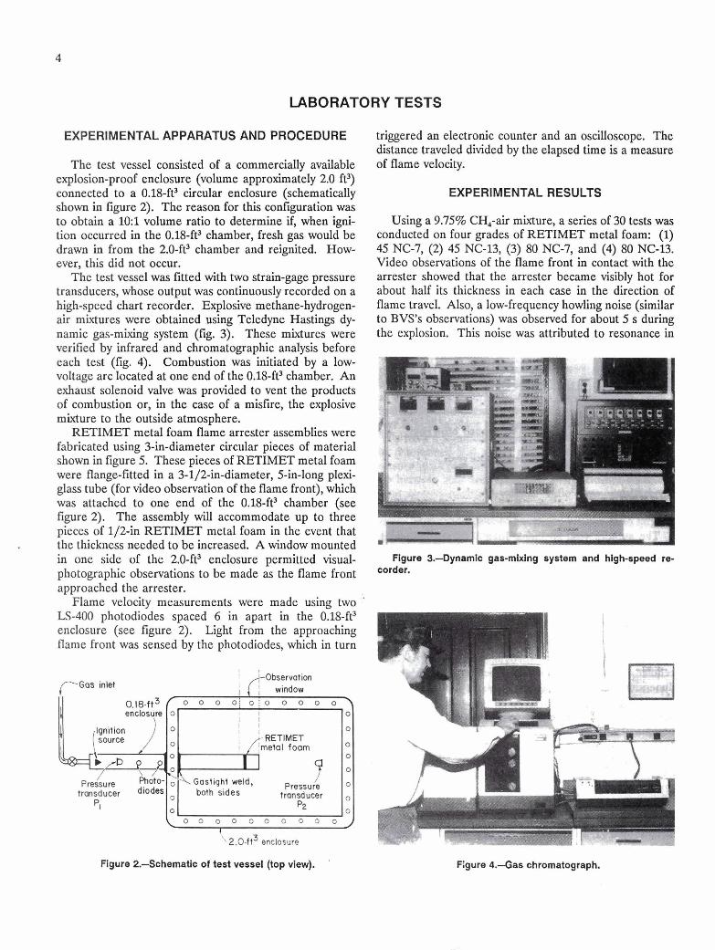
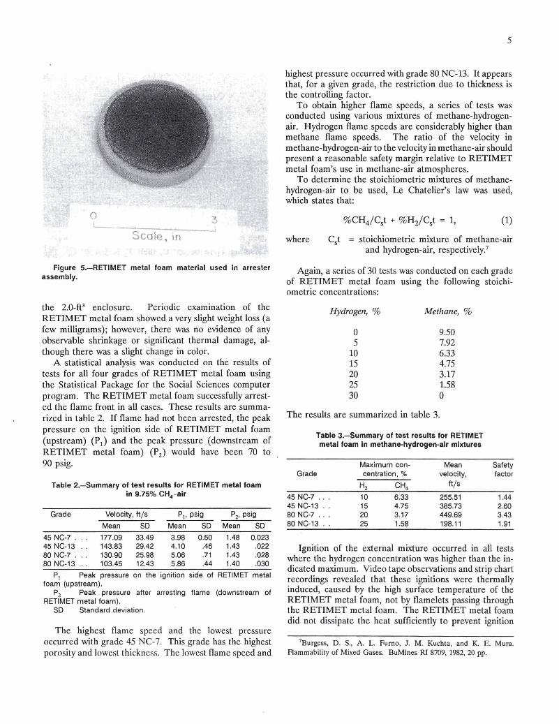
The test vessel was fitted with two strain-gage pressure transducers, whose output was continuously recorded on a high-speed chart recorder. Explosive methane-hydrogen- air mixtures were obtained using Teledyne Hastings dy- namic gas-mixing system (fig. 3). These mixtures were verified by infrared and chromatographic analysis before each test (fig. 4). Combustion was initiated by a low- voltage arc located at one end of the 0.18-ft3 chamber. An exhaust solenoid valve was provided to vent the products of combustion or, in the case of a misfire, the explosive mixture to the outside atmosphere.
RETIMET metal foam flame arrester assemblies were fabricated using 3-in-diameter circular pieces of material shown in figure 5. These pieces of RETIMET metal foam were flange-fitted in a 3-112-in-diameter, 5-in-long plexi- glass tube (for video observation of the flame front), which was attached to one end of the 0.18-fP chamber (see figure 2). The assembly will accommodate up to three pieces of 112-in RETIMET metal foam in the event that the thickness needed to be increased. A window mounted in one side of the 2.0-ft3 enclosure permitted visual- photographic observations to be made as the flame front approached the arrester.
Flame velocity measurements were made using two '
LS-400 photodiodes spaced 6 in apart in the 0.18-ft3 enclosure (see figure 2). Light from the approaching flame front was sensed by the photodiodes, which in turn
(-Gas inlet Observation
window
! \ 2.0-ft3 enclosure
Figure 2.-Schematic of test vessel (top view).
triggered an electronic counter and an oscilloscope. The distance traveled divided by the elapsed time is a measure of flame velocity.
EXPERIMENTAL RESULTS
Using a 9.75% CH,-air mixture, a series of 30 tests was conducted on four grades of RETIMET metal foam: (1) 45 NC-7, (2) 45 NC-13, (3) 80 NC-7, and (4) 80 NC-13. Video observations of the flame front in contact with the arrester showed that the arrester became visibly hot for about half its thickness in each case in the direction of flame travel. Also, a low-frequency howling noise (similar to BVS's observations) was observed for about 5 s during the explosion. This noise was attributed to resonance in
Flgure 3.4ynamlc gas-mixlng system and hlgh-speed re- corder.
Figure 4.--Gas chromatograph.
. . . . . . highest pressure occurred with grade 80 NC-13. It appears that, for a given grade, the restriction due to thickness is the controlling factor.
To obtain higher flame speeds, a series of tests was conducted using various mixtures of methane-hydrogen- air. Hydrogen flame speeds are considerably higher than methane flame speeds. The ratio of the velocity in methane-hydrogen-air to the velocity in methane-air should present a reasonable safety margin relative to RETIMET metal foam's use in methane-air atmospheres.
To determine the stoichiometric mixtures of methane- hydrogen-air to be used, Le Chatelier's law was used, which states that:
%CH4/Cst + %H2/Cst = 1, (1)
where C,t = stoichiometric mixture of methane-air and hydrogen-air, respectively?
the 2.0-ft3 enclosure. Periodic examination of the RETIMET metal foam showed a very slight weight loss (a few milligrams); however, there was no evidence of any observable shrinkage or significant thermal damage, al- though there was a slight change in color.
A statistical analysis was conducted on the results of tests for all four grades of RETIMET metal foam using the Statistical Package for the Social Sciences computer program. The RETIMET metal foam successfully arrest- ed the flame front in all cases. These results are summa- rized in table 2. If flame had not been arrested, the peak pressure on the ignition side of RETIMET metal foam (upstream) (P,) and the peak pressure (downstream of RETIMET metal foam) (P,) would have been 70 to 90 psig.
Table 2.-Summary of test results for RETIMET metal foam in 9.75% CH,-air
Grade Velocity, ft/s P,, psig p,, psig Mean SD Mean SD Mean SD
P, Peak pressure on the ignition side of RETIMET metal foam (upstream).
P, Peak pressure after arresting flame (downstream of RETIMET metal foam).
SD Standard deviation.
The highest flame speed and the lowest pressure occurred with grade 45 NC-7. This grade has the highest porosity and lowest thickness. The lowest flame speed and
Again, a series of 30 tests was conducted on each grade of RETIMET metal foam using the following stoichi- ometric concentrations:
Hydrogen, % Methane, %
The results are summarized in table 3.
Table 3.Summary of test results for RETIMET metal foam in methane-hydrogen-alr mixtures
Maximum con- Mean Safety Grade centration, % velocity, factor
'42 ' 3 4 ft /s 45 NG7 . . . 10 6.33 255.51 1.44 45 NC-13 . . 15 4.75 385.73 2.60 80 NC-7 . . . 20 3.17 449.69 3.43 80 NG13 . . 25 1.58 198.1 1 1.91
Ignition of the external mixture occurred in all tests where the hydrogen concentration was higher than the in- dicated maximum. Video tape observations and strip chart recordings revealed that these ignitions were thermally induced, caused by the high surface temperature of the RETIMET metal foam, not by flamelets passing through the RETIMET metal foam. The RETIMET metal foam did not dissipate the heat sufficiently to prevent ignition
'~urgess, D. S., A. L. Furno, J. M. Kuchta, and K. E. Mura. Flammability of Mixed Gases. BuMines RI 8709,1982,20 pp.
even though it arrested the initial flame front. There was a delay of approximately 2.5 s between the arrival of the flame front at the arrester face and ignition of the external mixture, indicative of a thermal ignition. Further increases in hydrogen concentrations beyond the point at which ther- mal ignitions occurred resulted in ignition flashthrough, which indicated that the flame velocity exceeded the maximum quenchable velocity.
Assuming that all of the heat from the explosion is transferred to the RETIMET metal foam (the metal foam assembly is plexiglass), an estimate of the RETIMET metal foam temperature can be made for a 25% H2-1.58% CH,-air mixture using grade 45 NC-13:
where
and
Q = v1 (H, of H2) + V2 (H, of CH4), (2)
Q = the total heat,
= 0.05 (57.8 kcal/mol) + 0.00314 (212.79 kcal/mol) = 3.56 kcal of total energy,
V1 = volume of hydrogen,
H, = heat of combustion,
V2 = volume of methane.
Assuming the RETIMET metal foam absorbed all of this energy and solving for temperature yields-
where
and
m = mass of RETIMET metal foam,
c = specific heat of RETIMET metal foam,
T2 = temperature of RETIMET metal foam,
T1 = ambient temperature.
Assuming T, to be 25" C, then T2 is 564.39' C. This temperature is above the autoignition temperature of hydrogen (400" C). This accounts for the thermal ignitions as opposed to ignition flashthrough. Although velocity ratios were used to define a safety factor here, autoignition temperature might be a more viable parameter when assessing the relative merits of RETIMET metal foam in flame-arresting applications, especially when used in gases other than methane. This is indicated by the fact that grade 80 NC-13 appears less safe than grades 80 NC-7 and 45 NC-13; however, it must be remembered that grade 80 NC-13 has the lowest porosity but can withstand higher maximum concentrations.
LARGE-SCALE TESTS
In general, the RETIMET metal foam performed well arrangement was to determine the minimum vent-area-to- as a flame arrester in laboratory experiments. It success- enclosure-volume ratio that will reduce the explosion pres- fully arrested the flame front in all tests using methane-air sure to a prescribed level and keep the external surface mixtures. No significant thermal damage occurred and no observable shrinkage was evident. However, the question
"
arose as to whether or not RETIMET metal foam could %
withstand the large quantity of heat generated by "large- t- '
volume" methane-air explosions. These concerns led to an . agreement with MSHA's Approval and Certification Cen- ter to test RETIMET metal foam on a large, commercial- I .. size enclosure.
EXPERIMENTAL APPARATUS AND PROCEDURE a
The test enclosure consisted of a 54.48-ft3 multi- compartmented, variable vent area enclosure designed jointly by the Bureau and MSHA. The enclosure is partitioned into four volumes of 13.31, 13.63, 13.63, and 13.91 ft3 (fig. 6). There are four covers with vent areas of 36, 64,100, and 150 in2. (Three are shown in figure 7; Figure 6.-Multlcompartmented variable vent area enclosure the 150-in2 vent is not shown.) Again, the purpose of this In MSHA's 500-ft3 explosion gallery In Trladelphla, WV.
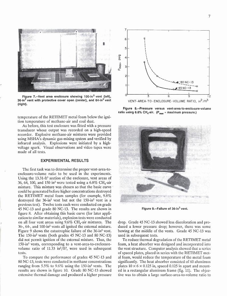
Figure 7.-Vent area enclosure showing 100-in2 vent (left), 36-in2 vent with protectlve cover open (center), and 64-in2 vent (right).
temperature of the RETIMET metal foam below the igni- tion temperature of methane-air and coal dust.
As before, this test enclosure was fitted with a pressure transducer whose output was recorded on a high-speed recorder. Explosive methane-air mixtures were provided using MSHA's dynamic gas-mixing system and verified by infrared analysis. Explosions were initiated by a high- voltage spark. Visual observations and video tapes were made of all tests.
EXPERIMENTAL RESULTS
The first task was to determine the proper vent-area-to- enclosure-volume ratio to be used in the experiments. Using the 13.31-ft3 section of the enclosure, vent areas of 36, 64, 100, and 150 in2 were tested using a 6.8% CH,-air mixture. This mixture was chosen so that the basic curve , could be generated before higher concentrations destroyed the RETIMET metal foam samples (for example, 9.8% destroyed the 36-in2 vent but not the 150-inz vent in a previous test). Twelve tests each were conducted on grade 45 NC-13 and grade 80 NC-13. The results are shown in figure 8. After obtaining this basic curve (for later appli- cation to similar materials), explosion tests were conducted on all four vent areas using 9.6% CH,-air mixtures. The 36-, 64-, and 100-in2 vents all ignited the external mixture. Figure 9 shows the catastrophic failure of the 36-in2 vent. The 150-in2 vents (both grades 45 NC-13 and 80 NC-13) did not permit ignition of the external mixture. Thus, the 150-in2 vents, corresponding to a vent-area-to-enclosure- volume ratio of 11.33 in2/ft3, were used in subsequent tests.
To compare the performance of grades 45 NC-13 and 80 NC-13, tests were conducted in methane concentrations ranging from 5.5% to 9.6% using the 150-in2 vents. The results are shown in figure 10. Grade 80 NC-13 showed extensive thermal damage and produced a higher pressure
Figure 8.--Pressure versus vent-area-to-enclosure-volume ratio usin$ 6.8% CHCair. (P, = maximum pressure.)
Figure 9.--Failure of 36-111' vent
drop. Grade 45 NC-13 showed less discoloration and pro- duced a lower pressure drop; however, there was some bowing at the middle of the vents. Grade 45 NC-13 was used in subsequent tests.
To reduce thermal degradation of the RETIMET metal foam, a heat absorber was designed and incorporated into the vent structure. Computer analysis showed that a series of spaced plates, placed in series with the RETIMET met- al foam, would reduce the temperature of the metal foam significantly. The heat absorber consisted of 60 aluminum plates 10 x 6 x 0.125 in, spaced 0.125 in apart and mount- ed in a rectangular aluminum frame (fig. 11). The objec- tive was to obtain a large surface-area-to-volume ratio to
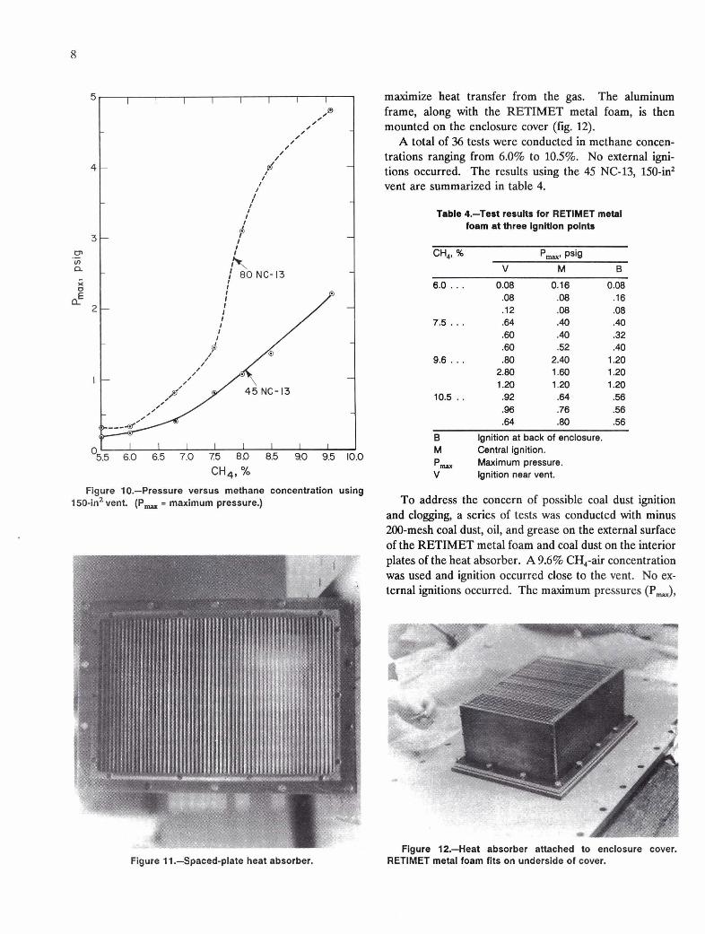
Figure 10.-Pressure versus methane concentration using 1 50-in2 vent (P, = maximum pressure.)
Figure 11,-Spaced-plate heat absorber.
maximize heat transfer from the gas. The aluminum frame, along with the RETIMET metal foam, is then mounted on the enclosure cover (fig. 12).
A total of 36 tests were conducted in methane concen- trations ranging from 6.0% to 10.5%. No external igni- tions occurred. The results using the 45 NC-13, 150-in2 vent are summarized in table 4.
Table 4.-Test results for RETIMET metal foam at three Ignition points
6.0 . . . 0.08 0.16 0.08 .08 -08 .16 .12 .08 .08 .64 .40 .40 .60 .40 .32 .60 .52 -40 -80 2.40 1.20
2.80 1.60 1.20 1.20 1.20 1.20 .92 .64 .56 .96 .76 .56 .64 -80 .56
B Ignition at back of enclosure. M Central ignition. P, Maximum pressure. V Ignition near vent.
To address the concern of possible coal dust ignition and clogging, a series of tests was conducted with minus 200-mesh coal dust, oil, and grease on the external surface of the RETIMET metal foam and coal dust on the interior plates of the heat absorber. A 9.6% CH,-air concentration was used and ignition occurred close to the vent. No ex- ternal ignitions occurred. The maximum pressures (Pa,
Figure 12.--Heat absorber attached to enclosure cover. RETIMET metal foam fits on underside of cover.
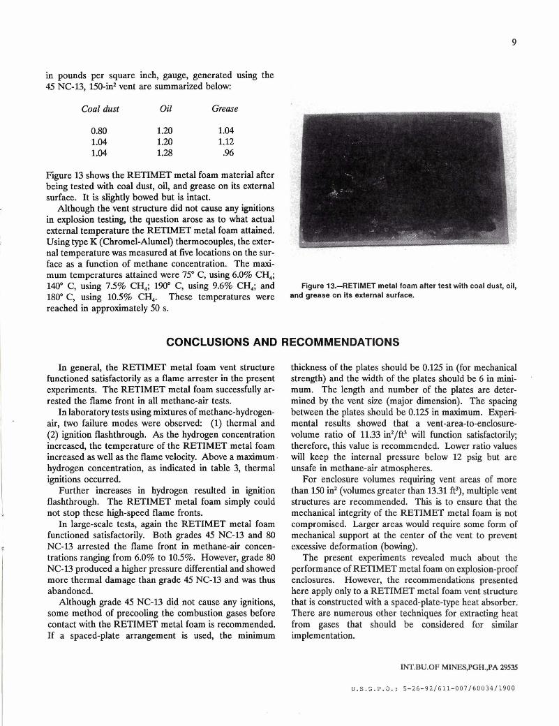
in pounds per square inch, gauge, generated using the 45 NC-13, 150-in2 vent are summarized below
Coal dust Oil Grease
0.80 1.20 1.04 1.04 1.20 1.12 1.04 1.28 .%
Figure 13 shows the RETIMET metal foam material after "
being tested with coal dust, oil, and grease on its external '
surface. It is slightly bowed but is intact. Although the vent structure did not cause any ignitions
in explosion testing, the question arose as to what actual external temperature the RETIMET metal foam attained. : Using type K (Chromel-Alumel) thermocouples, the exter- nal temperature was measured at five locations on the sur- face as a function of methane concentration. The maxi- mum temperatures attained were 75" C, using 6.0% CH,; 140" C, using 7.5% CH,; 190" C, using 9.6% CH,; and Figure 13.-RETIMET metal foam after test with coal dust, oil, 180" C, using 10.5% CH,. These temperatures were and grease on its external surface- reached in approximately 50 s.
CONCLUSIONS AND RECOMMENDATIONS
In general, the RETIMET metal foam vent structure functioned satisfactorily as a flame arrester in the present experiments. The RETIMET metal foam successfully ar- rested the flame front in all methane-air tests.
In laboratory tests using mixtures of methane-hydrogen- air, two failure modes were observed: (1) thermal and (2) ignition flashthrough. As the hydrogen concentration increased, the temperature of the RETIMET metal foam increased as well as the flame velocity. Above a maximum. hydrogen concentration, as indicated in table 3, thermal ignitions occurred.
Further increases in hydrogen resulted in ignition flashthrough. The RETIMET metal foam simply could not stop these high-speed flame fronts.
In large-scale tests, again the RETIMET metal foam functioned satisfactorily. Both grades 45 NC-13 and 80 NC-13 arrested the flame front in methane-air concen- trations ranging from 6.0% to 10.5%. However, grade 80 NC-13 produced a higher pressure differential and showed more thermal damage than grade 45 NC-13 and was thus abandoned.
Although grade 45 NC-13 did not cause any ignitions, some method of precooling the' combustion gases before contact with the RETIMET metal foam is recommended. If a spaced-plate arrangement is used, the minimum
thickness of the plates should be 0.125 in (for mechanical strength) and the width of the plates should be 6 in mini- mum. The length and number of the plates are deter- mined by the vent size (major dimension). The spacing between the plates should be 0.125 in maximum. Experi- mental results showed that a vent-area-to-enclosure- volume ratio of 11.33 in2/ft3 will function satisfactorily; therefore, this value is recommended. Lower ratio values will keep the internal pressure below 12 psig but are unsafe in methane-air atmospheres.
For enclosure volumes requiring vent areas of more than 150 in2 (volumes greater than 13.31 W), multiple vent structures are recommended. This is to ensure that the mechanical integrity of the RETIMET metal foam is not compromised. Larger areas would require some form of mechanical support at the center of the vent to prevent excessive deformation (bowing).
The present experiments revealed much about the performance of RETIMET metal foam on explosion-proof enclosures. However, the recommendations presented here apply only to a RETIMET metal foam vent structure that is constructed with a spaced-plate-type heat absorber. There are numerous other techniques for.extracting heat from gases that should be considered for similar implementation.
1NT.BU.OF MINES,PGH.,PA 29535
U.S.S.P.O.: 5-26-92/611-007/60034/1900