Embed Size (px)
Citation preview

UCRL-JC-132679 Preprint
Performance Results of the High Gain, Nd: Glass, Engineering Prototype Preamplifier Module (PAM)
for the National Ignition Facility (NIF)
M. D. Martinez, K. M. Skulina, F. J. Deadrick, J. K. Crane, B. Moran, J. Braucht, B. Jones, S. Hawkins,
R. Tilley, J. Crawford, D. Browning and F. Penko
This paper was prepared for submittal to Photonics West 99 Symposium
San Jose, CA January 23-29,1999
February 9,1999
This is a preprint of a paper intended for publication in a journal or proceedin; Since changes may be made before publication, this preprint is made available with the understanding that it will not be cited or reproduced without the permission of the author.

DISCLAIMER
This document was pre ared as an account of work sponsored by an agency of the United States Government. Neither tl e United States Government nor the University of California nor any of their employees, makes any warranty, express or implied, or assumes any legal liability or responsibility for the accuracy, completeness, or usefulness of any infonnation, apparatus,
If mduct, or process disclosed, or
represents that its use would not infringe privately owned rights. eference herein to any specific commercial product, process, or service by trade name, trademark, manufacturer, or otherwise, does not necessarily constitute or imply its endorsement, recommendation, or favoring by the United States Government or the University of California. The views and opinions of authors expressed herein do not necessarily state or reflect those of the United States Government or the University of California, and shall not be used for advertising or product endorsement purposes.
Performance results of the high gain, Nd:Glass, engineering prototype preamplifier module (PAM) for the National Ignition
Facility (NIP)
Mikael D. Martinez, Kenneth .M. Skulina, Fred .J. Deadrick, John .K. Crane, Bryan Moran, John Braucht, Bobby Jones, Steve Hawkins, Ron Tilley, James Crawford,
Donald Browning, and Frank. Penko
Lawrence Livermore National Laboratory M.S. L-483 7000 E. Ave
Livermore, CA 94550
ABSTRACT We describe recent, energetics performance results on the engineering preamplifier module (PAM) prototype located in the front end of the 1.8MJ National Ignition Facility (NIF ) laser system. Three vertically mounted subsystem located in the PAM provide laser gain as well as spatial beam shaping. The first subsystem in the PAM prototype is a diode pumped, Nd:glass, linear, TEMoo , 4.5m long regenerative amplifier cavity. With a single diode pumped head, we amplify a lnJ, mode matched, temporally shaped (= 20ns) seed pulse by a factor of approximately 10 to 20mJ. The second subsystem in the PAM is the beam shaping module, which magnifies the gaussian output beam of the regenerative amplifier to provide a 30mm X 30mm square beam that is spatially shaped in two dimensions to pre-compensate for radial gain profiles in the main amplifiers. The final subsystem in the PAM is the 4-pass amplifier which relay images the 1mJ output of the beam shaper through four gain passes in a $5cm X 48cm flashlamp pumped rod amplifier, amplifying the energy to 175. The system gain of the PAM is 10”. Each PAM provides 35 of injected energy to four separate main amplifier chains which in turn delivers 1.8MJ in 192 frequency converted laser beams to the target for a broad range of laser fusion experiments.
Keywords: NIF, Nd:Glass, diode pumped, pre-amplifier, SSD
1. INTRODUCTION The National Ignition Facility (NIF) is a high energy laser system being developed, designed and constructed for the United States Department of Energy at Lawrence Livermore National Laboratory (LLNL) in Liver-more California. This solid state, Nd:Glass laser system will be used for a wide range of Inertial Confinement Fusion (ICF) experiments as well as high temperature and high density physics research”‘. NIF will continue and expand physics research performed by its predecessor the NOVA laser system here at LLNL. The NOVA laser culminated from 9 years of solid state laser development and in 1984 was the first laser to be used for ICF experiments using ultraviolet, frequency converted light. The NIF laser system will deliver 1.8MJ/SOOTW of ultraviolet light to target in 192 separate beamlines. This is a twenty fold increase in energy from the 10 beam NOVA laser system. The figure below shows what the NIF site will look like after full system activation in 2003.

Control room Ma*tB, o*cillator room
Figure 1. Diagram of what the NIF site will look like.
The NIF laser also incorporates a fundamentally different architecture than NOVA’s single pass amplifier scheme. With the increase in beamlines. optical components and the shear size of the laser building, NIF had to be designed with cost and packaging in mind. To reduce costs and size, the NIF laser will utilize multi-passing 40cmX40cm2Brewster slab amplifiers which reduces the number of optical components as well as improves saturation of the amplifiers.
The NIF Front End or OPG consists of an all fiber-based master oscillator”’ that generates an optical pulse which is subsequently phase modulated and temporally shaped with a pulse duration of up to 2111s. This specially tailored pulse is then propagated via polariz ing (P Z) fiber to a series of optical splitters and ampliiiers. The splitters generate 48 amplified pulses of I nJ which are injected into 48 separate PAM’s via PM fiber. Each PAM output is then split into four separate beams in the Preamplifier Beam Transport System (PABTS) and injected into the I92 main amplifier chains. The NIF subsystems: Master Oscillator Room ( MOR), PAM and PABTS are combined into a system called the NIF Front End or Optical Pulse Generation(OPG) system. Below is a block diagram describing the OPG system.
Figure 2. Block diagram of subsystems located in NIF front end or OPG
Each PAM consists of a diode-pumped, Nd:glass regenerative amplifier”‘. a spatial- beam-shaping subsystem, and a flashlamp pumped, multi-pass amplifier’4’. The PAMs produce the largest optical gain of the entire NIF laser system, boosting the InJ master oscillator pulse to 16.95. The total gain of each preamplifier is 2 x IO’“. All PAM laser subsystems are mounted on a double-sided, vertical, optical table housed in the optical support structure (OSS) which rolls on precision rails for rapid on-line installment. The regenerative amplifier and beam shaper are mounted on one side and feed light through a clearance hole to inject the 4-pass amplifier on the other side of the optical table. Figure 3 is a schematic diagram of a PAM showing its component subsystems: fiber injection, diode-pumped regenerative amplifier, spatial beam shaping, SSD, and the 4-pass amplifier.
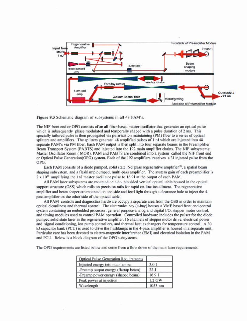
Figure 9.3 Schematic diagram of subsystems in all 48 PAM’s
The NIF front end or OPG consists of an all fiber-based master oscillator that generates an optical pulse which is subsequently phase modulated and temporally shaped with a pulse duration of 2lns. This specially tailored pulse is then propagated via polarization maintaining (PM) fiber to a series of optical splitters and amplifiers. The splitters generate 48 amplified pulses of I nJ which are injected into 48 separate PAM’s via PM fiber. Each PAM output is then split into four separate beams in the Preamplifier Beam Transport System (PABTS) and injected into the 192 main amplifier chains. The NIF subsystems: Master Oscillator Room ( MOR), PAM and PABTS are combined into a system called the NIF front end or Optical Pulse Generation(OPG) system. Each ofthe 192 amplifiers, receives a 35 injected pulse from the OPG.
Each PAM consists of a diode pumped, solid state, Nd:glass regenerative amplifv#‘, a spatial beam shaping subsystem, and a tlashlamp pumped, multi-pass amplifier. The system gain of each preamplifier is 2 x 10”’ amplifying the InJ master oscillator pulse to l6.9J at the output of each PAM.
All PAM laser subsystems are mounted on a double sided vertical optical table housed in the optical support structure (OSS) which rolls on precision rails for rapid on-line installment. The regenerative amplifier and beam shaper are mounted on one side and feed light through a clearance hole to inject the 4. pass amplifier on the other side of the optical table.
All PAM controls and diagnostics hardware occupy a separate area from the OSS in order to maintain optical cleanliness and thermal control. The electronics bay (e-bay) houses a VME based front end control system containing an embedded processor, general purpose analog and digital I/O, stepper motor control, and timing modules used to control PAM operation. Controlled hardware includes the pulser for the diode pumped solid state laser in the regenerative amplifier, 16 channels of stepper motor drive, electrical power and signal conditioning, ion pump controllers, and thermal heat exchangers for temperature control. A 30 kJ capacitor bank (PCU) is used to drive the flashlamps in the 4-pass amplifier is housed in a separate unit. Particular care has been devoted to electro-magnetic interference (EMI) and electrical isolation in the PAM and PCU. Below is a block diagram of the OPG subsystems.
The OPG requirements arc listed below and come from a flow down of the main laser requirements.

Pulse duration Power balance (in 2 ns window) Power dynamic range Square-pulse-distortion Prepulse contrast Number of preamplifier modules
Table 1. General requirements for the OPG’7’.
20 ns <3% >125:1 ~2.3 >2X10”6 48
2.0 DESCRIPTION
2.1 Regenerative amplifier The regenerative amplifier is the first stage of amplification in the PAM and represents the largest gain
component in the NIF laser system.
Master Oscillator PM Fiber
Cavity Slicer
3utput Slicer
Figure 4. Optical layout of the regenerative amplifier used in the pre-amplifier module of the NIF. A single solid state amplifier is end pumped by a laser diode array and provides the required single pass gain of 1.6 per pass An injected beam is captured in the cavity for 27 passes, amplifying the beam energy from 1 nJ to a 23 mJ output. The beam is coupled out by means of polarization switching.
This regenerative amplifier is comprised of a folded, linear, 4..5m, TEM, cavity using a diode-pumped, phosphate glass rod in an end-pumped configuration. A master oscillator pulse, is injected into the regenerative amplifier at the fiber launch. Refer to Figure 4 for the optical layout of the regenerative amplifier. Using both the fiber launch lens (Ll) and a second lens (L2) we form a telescope that matches the spatial mode of the seed beam to the eigenmode of the TEM,cavity. The seed also propagates through a dual stage Faraday isolator that protects the fiber from the much higher energy output leakage which propagates in the reverse direction. After the telescope, the beam propagates through a thin film polarizer (TFPl) which functions as the output coupler of the amplifier. The seed then propagates through a Faraday rotator and half wave plate that act as a directional coupler, separating the injected input from the regen output pulse Mirrors Ml and M2 are used to point and center the injected pulse into the cavity. The p-polarized seed is injected into the cavity through the thin film polarizer TFP2, goes through a 3m focal length cavity lens and mode limiting aperture. By adjusting the size of this aperture we force the cavity to operate in a single TEM, spatial mode. Within the cavity the seed makes a Z-fold via mirrors M3 and M4, passes through the quarter waveplate the Q-switch Pockels cell (QS-PC) and into the amplifier head. It then reflects off the high reflectivity coating end of the rod reversing direction back through the cavity. With the QS-PC turned off, the polarization of the seed rotates 90 degrees from P to S due to double passing the quarter-waveplate and propagates back along its original path through the lens, aperture and reflects off of TFP2, propagating to mirror M5 and mirror M6. The mirrored end of the diode pumped amplifier rod and mirror M6 form the end mirrors of a linear cavity. Energizing the QS-PC traps the pulse in the cavity for 20-40 round trips. When the pulse is amplified to the desired energy , the QS- PC is switched off and the pulse is ejected from the cavity and reflects off of TFPl and travels to the output

slicer. The slicer PC is turned on long enough to pass the desired output pulse while eliminating unwanted prep&xx that leak out of the regen. Following the output slicer, part of the beam is monitored with a photodiode. A motorized centering glass is then used to rccovcr any alignment errors and mirrors MS and M9 direct light to the beam shaping module (BSM)
2.2 Beam shaping module The beam shaping module, Iocatcd aftcr the rcgcnerative amplifier (regen), provides several functions.
First, the 20X telescope, magnifies the Gaussian-shaped regen beam to over fill the shaping filters and apodizers that provide the desired shape injected into the 4.pass. Second, pixel&d, chrome-on-glass filters spatially shape the beam to pre-compcnsatc for the radial gain profiles of the main amplifiers, to provide a spatially flat-topped beam at target. Third, a serrated apodizer shapes the edge of the beam to minimize diffraction ringing and limit laser damage as the beam propagales through the rest of the system’“’ Fourth, motorized stages provide rapid in situ placement of two different serrated apertures for different ICF missions. The output of the beam shaper is then folded to the other side of the table to be injected into the 4.pass amplifier. See Figure 5 below for a schematic of the BSM.
Figure 5. Diagram of beam shaping module used in NIF to expand, shape and provide 30mm X 30mm beam to be injected into the 4.pass amplifier.
2.3 4-pass amplifier/lD SSD The 4.pass amplifier is the second gain component in the PAM. This relay imaged, linear amplifier
provides a gain of about IO’ as well s a user sclectahle, inter-cavity diffraction graling at Littrow for one dimensional smoothing by spectral dispersion (ID SSD).

Figure 6. Optical layout of flashlamp pumped 4-pass amplifier 16.9 J is extracted in four passes giving a net gain of 103.
The 4-pass amplifier is a passively switched linear amplifier which uses a 45 degree Faraday rotator, polarizers and a half waveplate to couple light into and out of the amplifier cavity providing four gain passes through the rod amplifier. A $5cm x 48cm phosphate glass rod is pumped by 6 series flashlamps to provide the gain in the system. Three vacuum relay telescopes provide gain hold off, spatial filtering of high frequency components as well as relay imaging of the serrated aperture to prescribed locations in the cavity, The telescope, RTl, relays the serrated aperture to the center of the rod amplifier. The amplifier cavity is formed by the combination of mirrors, M4,M3, M2, M5, and telescopes RT2 and RT3. The image of the serrated aperture relayed to the center of the rod, is subsequently relayed to the cavity end mirrors, M4 and M5, using the cavity telescopes RT2 and RT3. The quarter waveplate controls the polarization so the amplified pulse makes four passes through the rod, then out of the cavity via the two thin-film polarizers. The cavity Faraday rotator, FR2, compensates for thermal and stress-induced birefringence from the rod and vacuum spatial filters by rotating the noncircular polarization components by 90 degrees”‘.
In all of the relay telescopes, each gain pass is separated by a field angle that helps isolate these passes to aid in holding off the gain which can cause parasitic oscillations. Following is a diagram of the pinhole configuration in the 4-pass telescopes.
RT 1 RT2 RT3
@@@
Viewed from Viewed from Ml to TFP2 M3 to M4 TFP3 to M5/Gl
Figure 7. Pinhole configuration with field angle in the 4-pass cavity which helps with parasitic gain hold off.
3.1.1. Regenerative amplifier 3.0 RESULTS
Given the requirements for the entire OPG, we flow down these system requirements to the individual subsystems. Following is a list of requirements for the regenerative amplifier.

Table 2. NIF regenerative amplifier performance requirements.
The first energetics measurement made on the regenerative amplifier in the PAM was to evaluate the single pass gain of the diode pumped head. This will tell us if the regenerative amplifier has the gain and stored energy to meet the NIF requirements.
Using a cw Nd:YLF laser as a probe, we measured the double-pass gain of the end pumped rod amplifier as a function of pump diode driver current. The results are shown below along with a photo of the diode pumped head.
Figure 8. Photograph of diode pumped rod amplifier including: laser rod, laser diodes and lens duct.
I
40 50 80 1w 120 140 160 180 DC.% Dri”srC”rranl CA1 I
Figure 9. Experimental results show a single pass gain of 1.6 for the diode pumped head.
A simple model agrees with the data at the lower gains. At high gain the data rolls off due to ASE depleting the gain The barrel of the diode pumped head is polished to support the TIR propagation of the pump light in the rod, but also supports the propagation of ASE which can itself extract energy from the rod.
One ofthe performance specifications of the NIF, is a precisely controlled temporal pulse shape at the target. A measure of temporal fidelity is square-pulse-distonion (SPD), which is the ratio of the gain at the leadine edge of a sauare pulse to the eain at the end of the wise. SPD=G(O)/ G(T). We measured SPD in
To’ dekrmine t& SPb of the reg&, we use a high banbwid~h (6Ghz)‘photo&iver to measure the injected pulse and a second high bandwidth detector to temporally resolve the regen output pulse. These input and output pulses are converted to optical power and divided to show gain versus pulse length. The

SPD is the ratio of the gain at the be innin 1 of the ulse , a6;, ,” , . ~~~~~:at,th,e;nd,ofthepulse.
Figure 10. Results of SPD at a specific measurement shows PAM regen exceeds NIF requirements.
fhe plot above shows that the PAM regen exceeds NIF requirements given in Table 2. 4 nJ from the master oscillator we extracted 23mJ out of the resen with an SPD of I .39. Following is a picture of the regenerative amplifier. I
- ..-%- - ‘c- !C - - -1 -
C-e -.....-W..-W--- ~. - .--- .-
By injecting
Figure I I. Photograph of regenerative amplifier shows critical components mounted on vertical laser table.
3.1.2 Beam shaping module The beam shaping module (BSM) was designed and built by an outside contractor. As described
above, this BSM mounted a 20X expanding telescope. two beam shaping masks, an alignment target and a serrated aperture. The BSM converts the Gaussian output of the regcneralive amplifier into a 30mm X 30mm square, apodized beam that is shaped to compensate for the spatial gain profiles of all the downstream amplifiers.. The serrated apertures and alignment masks are mounted on motorized stages to provide remote selection. Below is a picture of the BSM mounted on the vertical table with camera images of the small Gaussian input and spatially shaped output. measured at the four-pass output.

Figure 12. Beam injected il.
‘g module provides a pre-shaped, 30mm square beam from tt . . . . 4.pass pass amplifier,
to be
3.1.3 4-pass amplifier The last stage of amplification in the PAM is the 4-pass amplifier. A 30mmX30mm beam is injected
into the relay imaged cavity and passed four times through a $15cm X 48cm phosphate glass amplifier rod. Below is list ofrequirements for the 4-pass amplitier.
Output Energy 225 (Flat-topped beam) 14.55 (Spatially Shaped)
Peak Power 8.8GW SPD (PAM/4-pass) ~2.3 / <I .6
Injection Energy ImJ
Table 3. Energetics requirements list for the 4-pass amplifier.
In order to ensure the PAM would meet the energetics requirements, we characterized the 415cm rod amplifier for small signal gain and radial gain profile. With the small signal gain and cavity transmission, we can predict the amount of energy to be extracted for a given injected energy. The spatial profile of the gain media is needed to design the spatial beam shaping masks that produce the required shape injected into the main amplifiers.
With a +lOmm probe beam. we measured the centerline gain ofthe amplifier head using two calorimeters. Below is a plot of the small signal gain versus delivered electrical energy and explosion fraction of the flashlamps.
Figure 13. Results of measurements show a peak gain of 19

With a delivered electrical energy of 22kJ, we measure a single p g fraction of 0.17. This gain is sufticient to produce the energy requirem lent;
We measured the radial gain profile by imaging the center ofthe rc ,d at amphtier was used as the probe source and a reference image and gain image taken to determine the spatial1
,ain of I9 with an explosion listed in table 3. full aperture. The regenerative
of the center of the rod were n profile that we measured. lat ail
ll I
Figure 14. Radial gain profile measurement shows a relatively flat spatial gain protile
Using the regenerative amplifier as an alignment source, the 4-pass amplifier was as shown in F igure 4. Figure I5 is a picture of the amplifier moun!eg on the OSS.
;i “stalled and aligned
Figure 15. 4-pass amplifier is housed on one side of the optical support structure.
Once the 4-pass amplifier was installed and aligned, energy extraction measurements were conducted. Operating the @5cm amplifier at peak gain, we varied the energy injected into the 4-pass amplifier and measured the output energy. The plot in Figure I4 shows energy extracted from the four-pass versus input energy. The solid line shows predicted energy based on a Fran&Nodvik model”‘.

Figure 16.
I 1 PAY output energy,vs 4-pass input,energy x !I?
Results of energy extraction from 4-pass amplifier show the PAM excet NIF OPG requirement of 225 unshaped.
Is the
For an input energy of 488pJ into the 4-pass cavity, we extracted 245. This exceeds the 223 requirement listed in Table 3 for an unshaped beam.
4.0 CONCLUSION
We have completed the construction and alignment of the high gain, Nd:glass NIF prototype pre- amplifier module. Using the general laser design developed on a physics testbed (‘?o meet NIF laser requirements, we have packaged the amplifier system in the optical support structure (OSS). This support structure is designed as a line replaceable unit(LRU). This LRU design provides rapid installment and removal to meet NIF shot rate requirements. Also, an electronics bay housed on the OSS provides controls and diagnostics. The PAM will remotely provide alignment for the laser system as well as define the level of energy injected into the main amplifiers which in turn defines energy delivered to target.
We have successfully demonstrated a fully integrated PAM prototype that exceeds NlF performance specifications for output energy, power and temporal pulse distortion. We continue to work to demonstrate the full performance requirements of the preamplifier-prototype before integrating with the OPG systems, MOR and PABTS, to demonstrate performance of the entire front end.
5.0 ACKNOWLEDGMENTS Work done under the auspices of the U.S. Department of Energy by Lawrence Livermore National
Laboratory under contract No. W-7405-Eng-48.
6.0 REFERENCES 1. Overview of the National Ignition Facility, John R. Murray, supplement to Proceedings of SPIE vol. 3492 pps. l- 10, 3rd International Conference Solid State lasers for Application to Inertial Confinement Fusion, Monteray, Ca Jun. 1998.
2. S.C. Burkhart, R. Wilcox, D. Browning, F. Penko, “Amplitude and Phase Modulation with Waveguide Optics”, Proc. 1st International Con. On Solid State Laser for Application to Inertial Confinement Fusion, Monterey, 3047, p. 610-617, SPIE Proceedings Series Bellingham, WA, 1995
3. J. Crane, M. Martinez, R. Beach, S. Mitchell, G Pratt, and J. Christensen, “Ultra-Stable, diode pumped Nd-doped glass regenerative amplifier for the National Ignition Facility (NIF)“, Conference on Laser Eelectro-Optics (CLEO), CW03, pp 324-325, 1996.
4. B.D. Moran, C.B. Dane, J.K. Crane, M.D. Martinez, F. Penko, L.A. Hackel, “Suppression of Paracitics and Pencil Beams in the High-Gain National Ignition Facility Multipass Preamplifier”, Proc. on Optoelectronics and High-Power Lasers and Applications, 3264, pp 56-64 SPIE Proceedings Series Bellingham, WA, 1998

5. M.D. Martinez, J.K. Crane, L.A. Hackel, “Optimized, diode-pumped, Nd:Glass, Prototype Regenerative Amplifier for the National Ignition Facility”, Proc. on Laser resonators, 3267, pp. 234-242, SPIE Proceedings Series Bellingham, WA 1998.
6. M. Henesian, J. K. Crane, C. B. Dane, J. Davin, L. Kott, C. Laumann, J. Lawson, M. Martinez, B. Moran, J. Miller, R. Sacks, K. Skulina, W. Williams, “Diffraction modeling of the National Ignition Facility PIF) Optical Pulse Generation (OPG) system and integration into the end-to-end system model”, Proc. 3’ International Conf On Solid State Lasers for Application to Inertial Confinement Fusion, Monterey, to be published, SPIE Proceedings Series, Bellingham, WA.
7. J. K. Crane. M. Martinez, B. Moran, C. Laumann, J. Davin, R. Beach, B. Golick, R. Jones, J. Braucht, M. Perry, K. Skulina, F. Penko, S. Herman, S. Burkhart, S. Mitchell, “ Description and performance of the preamplifier for the National Ignition Facility (NIF) laser system”, Proc. .Yd International ConJ On Solid State Lasers for Application to Inertial Confmement Fusion, Paris, France, 3047, pp. 601-609, SPIE Proceedings Series, Bellingham, WA, 1997.
8. L.M. Frantz, J. S. Nodvik, “Theory of Pulse Propagation in a Laser Amplifier”, J. Appl. Physics, 64, 2346-2349, (1963).
9. J. K. Crane, R. B. Wilcox, N. W. Hopps, D. Browning, M. D. Martinez, B. Moran, F. Penko, J. E. Rothenberg, M. Henesian, C. B. Dane, and L. A. Hackel, “Integrated operations of the National Ignition Facility (NIF) Optical Pulse Generation Development System”, Proc. 3rd International Co& On Solid State Lasers for Application to Inertial Confinement Fusion, Monterey, to be published, SPIE Proceedings Series, Bellingham, WA.