Embed Size (px)
Citation preview
Document ID: SPC-391
Effective Date: 7/23/02 Revision ID: 0
Performance Specification
PROJECT FILE NO. 021050
HEPA Filter Systems for the OU 7-10 Glovebox Excavator Method Project
Prepared for: US. Department of Energy Idaho Operations Office Idaho Falls, Idaho
Idaho ~ n a ~ Engineetlnu \/ and Environmental LahDratOn
Form 412.14 07/24/2001 Rev. 03
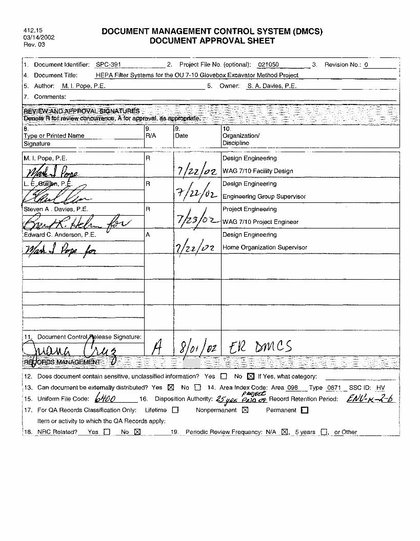
412.15 0311 412002 Rev. 03
Type or Printed Name Signature
DOCUMENT MANAGEMENT CONTROL SYSTEM (DMCS) DOCUMENT APPROVAL SHEET
WA Date Organization/ Discipline
1. Document Identifier: SPC-391 2. Project File No. (optional): 021050 3. Revision No.: 0
4. Document Title: HEPA Filter Systems for the OU 7-10 Glovebox Excavator Method Project
5. Author: M. I. Pope, P.E. 5. Owner: S. A. Davies, P.E.
17. Comments:
REVIEW AND APPROVAL SIGNATURES Denote R for review concurrence, A for approval, as appropriate.
8. 19. 19. 110.
M. I. Pope, P.E. IR
Edward C. Anderson, P.E.
11. Document Controlfitease Signature:
Design Engineering
3 WAG 7/10 Facility Design
Design Engineering
Project Engineering
WAG 711 0 Project Engineer
Design Engineering
/ I
12. Does document contain sensitive, unclassified information? Yes [rl No If Yes, what category:
13. Can document be ex distributed? Yes No [rl 14. Area Index Code: Area 098 Type 0671 SSC ID: HV
15. Uniform File Code: 16. Disposition Authority: Record Retention Period:
17. For QA Records Classification Only: Lifetime 0 Nonpermanent H Permanent
Item or activity to which the QA Records apply:
18. NRC Related? Yes 0 No 19. Periodic Review Frequency: NIA H, 5 years [rl, or Other
Specification
Environmental Restoration
412.09 (1 1/05/2001 . Rev . 06)
Identifier: SPC-391 Revision:
1 of 25
HEPA FILTER SYSTEMS FOR
EXCAVATOR METHOD PROJECT
THE OU 7-10 GLOVEBOX
CONTENTS
ACRONYMS .................................................................................................................................. 5
1 . SCOPE ................................................................................................................................ 7
1.1 General .................................................................................................................... 7
INEEL-Furnished Materials, Equipment, and Services .......................................... 7
1.2 Work Included ......................................................................................................... 7 1.3 Work Not Included .................................................................................................. 7 1.4
2 . APPLICABLE CODES. PROCEDURES. AND REFERENCES ...................................... 7
2.1 National Codes ........................................................................................................ 7
3 . TECHNICAL REQUIREMENTS ...................................................................................... 8
3.1
3.2
3.3
3.4 3.5 3.6
Make. Model. and Tag Numbers ............................................................................. 8
3.1.1 3.1.2 3.1.3 3.1.4 3.1.5 3.1.6 3.1.7 3.1.8 3.1.9
RCS Main Inlet Filter System ................................................................. 8 PGS #I Inlet Filter System ...................................................................... 9 PGS #2 Inlet Filter System ...................................................................... 9 PGS #3 Inlet Filter System .................................................................... 10 PGS #1 Drumout Tent Exhaust Filter Systems ..................................... 10
PGS #3 Drumout Tent Exhaust Filter Systems ..................................... 11
Main Exhaust Filter System .................................................................. 11
PGS #2 Drumout Tent Exhaust Filter Systems ..................................... 10
Personnel Access Room Exhaust Filter System .................................... 11
Requirements Applicable to All Equipment ......................................................... 13
3.2.1 Design Pressure ..................................................................................... 13 3.2.2 Seismic ................................................................................................... 13 3.2.3 Welding ................................................................................................. 13 3.2.4 Materials and Construction .................................................................... 13
BF-Series Filter Housings ..................................................................................... 14
3.3.1 General ................................................................................................... 14
G-Series Filter Housings ....................................................................................... 16 Heater Sections ...................................................................................................... 18 In-Place DOP Test Sections .................................................................................. 18
Specification
Environmental Restoration
4 .
5 .
6 .
7 .
8 .
HEPA FILTER SYSTEMS FOR
EXCAVATOR METHOD PROJECT
THE OU 7-10 GLOVEBOX
412.09 (1 1/05/2001 . Rev . 06)
Identifier: SPC-39 1 Revision:
2 of 25 I
3.6.1 General ................................................................................................... 18 3.6.2 Test Inlet Sections ................................................................................. 20 3.6.3 Test Combination Sections .................................................................... 20 3.6.4 Test Outlet Sections ............................................................................... 20
3.7 Isolation Dampers ................................................................................................. 20
3.7.1 Dampers ................................................................................................. 20 3.7.2 Actuators ................................................................................................ 20
3.8 Transitions ............................................................................................................. 21
QUALITY ASSURANCE ................................................................................................ 21
4.1 4.2 Quality Assurance Program .................................................................................. 21 4.3 Nondestructive Examination ................................................................................. 21 4.4 Operational Testing ............................................................................................... 21
Minimum Qualifications of Manufacturer. Supplier. or Personnel ...................... 21
INSTALLATION AND MAINTENANCE ...................................................................... 22
5.1 Installation ............................................................................................................. 22 5.2 Training ................................................................................................................. 22 5.3 Maintenance .......................................................................................................... 23
SUBMITTALS .................................................................................................................. 23
6.1 General Submittal Requirements .......................................................................... 23 6.2 Design Submittal ................................................................................................... 23 6.3 Materials Submittals .............................................................................................. 23 6.4 Construction Submittal .......................................................................................... 23 6.5 Test Submittals ...................................................................................................... 24
6.5.1 Test Procedures ...................................................................................... 24 6.5.2 Test Reports ........................................................................................... 24
6.6 Operating and Maintenance Manuals .................................................................... 24
PACKAGING AND SHIPPING ....................................................................................... 25
MARKING AND IDENTIFICATION ............................................................................. 25
9 . ACCEPTANCE ................................................................................................................. 25
412.09
Specification
Environmental Restoration
HEPA FILTER SYSTEMS FOR
EXCAVATOR METHOD PROJECT
THE OU 7-10 GLOVEBOX
(1 1/05/2001 - Rev. 06)
Identifier: SPC-39 1 Revision: 0 Page: 3 of 25
9.1 9.2
Final Acceptance Method ...................................................................................... 25 INEEL Surveillance and Audits ............................................................................ 25
10. ATTACHEMENTS ........................................................................................................... 25

' Specification
~ Environmental EXCAVATOR METHOD I Restoration PROJECT
HEPA FILTER SYSTEMS FOR THE OU 7-10 GLOVEBOX
412.09 (1 1/05/2001 - Rev. 06)
Identifier: SPC-391 Revision: 0 Page: 4 of 25
Specification HEPA FILTER SYSTEMS FOR THE OU 7-10 GLOVEBOX
Environmental EXCAVATOR METHOD Restoration PROJECT
ANSI
ASME
AWS
CMTR
DOP
HEPA
INEEL
iwg
NFPA
O&M
ou PGS
PVL
RCS
Identifier: SPC-391 Revision: 0 Page: 5 of 25
ACRONYMS
American National Standards Institute
American Society of Mechanical Engineers
American Welding Society
certified mill test report
dioctyl phthalate
high-efficiency particulate air
Idaho National Engineering and Environmental Laboratory
inches water gage
National Fire Protection Association
operations and maintenance
operable unit
Packaging Glovebox System
polyvinyl chloride
Retrieval Confinement Structure

412.09
Specification
Environmental Restoration
HEPA FILTER SYSTEMS FOR Identifier: SPC-391
EXCAVATORMETHOD Page: 6 of 25 THE OU 7-10 GLOVEBOX Revision: 0
PROJECT
Specification HEPA FILTER SYSTEMS FOR
Environmental EXCAVATOR METHOD Restoration PROJECT
THE OU 7-10 GLOVEBOX
1. SCOPE
1.1
Identifier: SPC-391 Revision: 0 Page: 7 of 25
1.2
1.3
1.4
General
This specification covers high-efficiency particulate air (HEPA) filter systems for installation in the Operable Unit (OU) 7- 10 Glovebox Excavator Method Project, located at the Radioactive Waste Management Complex, on the Idaho National Engineering and Environmental Laboratory (INEEL).
Work Included
Work included in this specification includes the following filter systems with individual components (as detailed in later sections of this specification):
e
e
e
e
a
Work Not Included
Not included in this specification are HEPA filters, which are purchased under a separate contract for the INEEL. The HEPA filters used by this project will be FlandersKSC GGF Nuclear Grade HEPA Filters.
INEEL-Furnished Materials, Equipment, and Services
No materials, equipment, or services will be provided by the INEEL.
One Retrieval Confinement System (RCS) inlet filter system
Three Packaging Glovebox System (PGS) inlet filter systems
Three PGS drumout tent exhaust filter systems
One personnel access room exhaust filter system
One main exhaust filter system.
2. APPLICABLE CODES, PROCEDURES, AND REFERENCES
The following codes, procedures, and references shall apply to the extent referenced to herein. Latest revisions in effect at the time of contract award shall apply unless otherwise noted.
2.1 National Codes
The following are national codes that apply to this specification:
Specification
Environmental Restoration
412.09 (1 1/05/2001 - Rev. 06)
Identifier: SPC-391 Revision:
8 of 25
HEPA FILTER SYSTEMS FOR
EXCAVATOR METHOD PROJECT
THE OU 7-10 GLOVEBOX
e ANSYASME, “Boiler and Pressure Vessel Code,” Section IX, American National Standards Institute/American Society of Mechanical Engineers
e ANSI/AWS D9.1, “Specifications for Welding Sheet Metal,” American National Standards Institute/American Welding Society
e ASME NQA-1 , “Quality Assurance Program Requirements for Nuclear Facilities,” American Society of Mechanical Engineers
e ASME N509, “Nuclear Power Plant Air Cleaning Units and Components,” American Society of Mechanical Engineers
e ASME N5 10, “Testing of Air Treatment Systems,” American Society of Mechanical Engineers
e “International Building Code”
e NFPA 90B, “Standard for the Installation of Warm Air Heating and Air-conditioning Systems,” National Fire Protection Association.
3. TECHNICAL REQUIREMENTS
3.1 Make, Model, and Tag Numbers
The following systems and components shall be supplied as specified below, with the manufacturer make and model numbers specified, or approved equals. Customer tag numbers, where applicable, are also included.
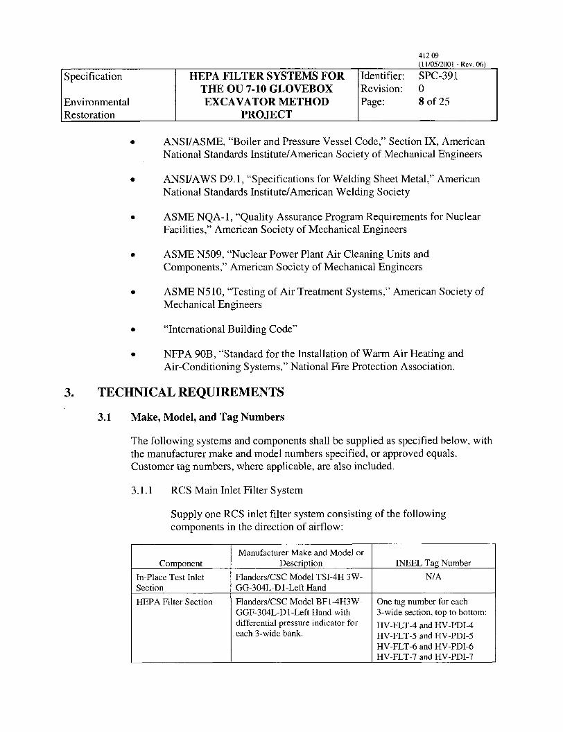
3.1.1 RCS Main Inlet Filter System
Supply one RCS inlet filter system consisting of the following components in the direction of aifflow:
ComDonent In-Place Test Inlet Section HEPA Filter Section
Manufacturer Make and Model or DescriDtion
FlandersKSC Model TSI-4H 3W- GG-304L-D 1 -Left Hand Flanders/CSC Model BF1-4H3W- GGF-304L-D1 -Left Hand with differential pressure indicator for each 3-wide bank.
INEEL Tag Number N/A
One tag number for each 3-wide section, top to bottom: HV-FLT-4 and HV-PDI-4 HV-FLT-5 and HV-PDI-5 HV-FLT-6 and HV-PDI-6 HV-FLT-7 and HV-PDI-7
Specification
Environmental Restoration
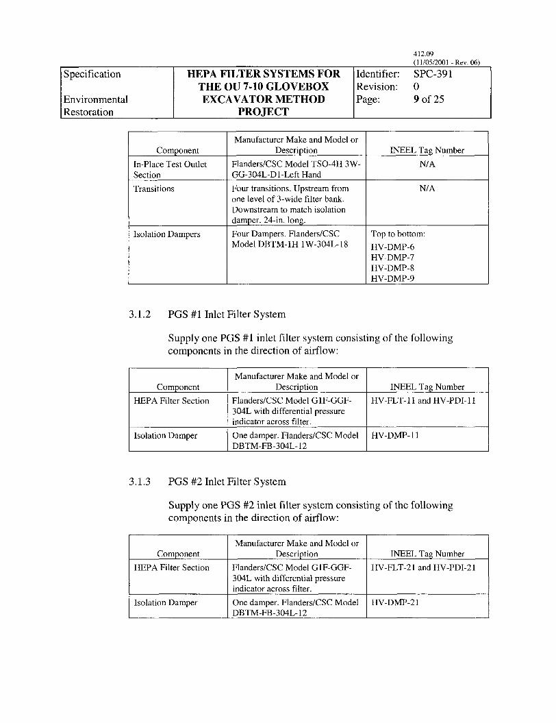
Component In-Place Test Outlet Section Transitions
HEPA FILTER SYSTEMS FOR
EXCAVATOR METHOD PROJECT
THE OU 7-10 GLOVEBOX
Isolation Dampers
Manufacturer Make and Model or
FlanderdCSC Model G1F-GGF- 304L with differential pressure indicator across filter. One damper. Flanders/CSC Model
Component Description HEPA Filter Section
1 Isolation Damper I DBTM-FB-304L- 12
412.09 (1 1/05/2001 - Rev. 06)
Identifier: SPC-391 Revision :
9 of 25
INEEL Tag Number HV-FLT-11 and HV-PDI-11
HV-DMP-11
~
Manufacturer Make and Model or Description
Flanders/CSC Model TSO-4H 3W- GG-304L-D I-Left Hand Four transitions. Upstream from one level of 3-wide filter bank. Downstream to match isolation damper. 24-in. long. Four Dampers. FlanderdCSC Model DBTM- 1H 1 W-304L- 18
Isolation Damper
3.1.2 PGS #1 Inlet Filter System
One damper. FlanderdCSC Model HV-DMP-2 1 DBTM-FB-304L- 12
INEEL Tag Number N/A
N/A
Top to bottom: HV-DMP-6 HV-DMP-7 HV-DMP-8 HV-DMP-9
3.1.3 PGS #2 Inlet Filter System
Supply one PGS #2 inlet filter system consisting of the following components in the direction of airflow:
HEPA Filter Section
Manufacturer Make and Model or DescriDtion
FlanderdCSC Model G1F-GGF- 304L with differential pressure indicator across filter.
INEEL Tag Number HV-FLT-2 1 and HV-PDI-2 1

Specification
Environmental Restoration
3.1.4 PGS #3 Inlet Filter System
HEPA FILTER SYSTEMS FOR
EXCAVATOR METHOD PROJECT
THE OU 7-10 GLOVEBOX
412.09 (1 1/05/2001 - Rev. 06)
Identifier: SPC-391 Revision':
10 of 25
Component HEPA Filter Section
Isolation Damper
Manufacturer Make and Model or
FlandersKSC Model G1F-GGF- 304L with differential pressure indicator across filter. One damper. Flanders/CSC Model
Description INEEL Tag Number HV-FXT-3 1 and HV-PDI-3 1
HV-DMP-3 1 DBTM-FB-304L- 12
3.1.5 PGS #1 Drumout Tent Exhaust Filter Systems
Component Isolation Damper
HEPA Filter Section
Isolation Damper
Supply one PGS #1 drumout tent exhaust filter system consisting of the following components:
Manufacturer Make and Model or
One damper. FlandersKSC Model
Flanders/CSC Model G1F-GGF- 304L with differential pressure indicator across filter. One damper. FlandersKSC Model HV-DMP-13
Description INEEL Tag Number HV-DMP- 12
HV-FLT- 12 and HV-PDI- 12 DBTM-Fl3-304L- 12
DBTM-FB-304L- 12
Component Isolation Damper
HEPA Filter Section
Isolation Damper
3.1.6 PGS #2 Drumout Tent Exhaust Filter Systems
Manufacturer Make and Model or
One damper. FlandersKSC Model HV-DMP-22
FlandersKSC Model G1F-GGF- 304L with differential pressure indicator across filter. One damper. FlandersKSC Model HV-DMP-23
Description INEEL Tag Number
DBTM-FB-304L- 12 HV-FLT-22 and HV-PDI-22
DBTM-FB-304L- 12
Supply one PGS #2 drumout tent exhaust filter system consisting of the following components:
Specification HEPA FILTER SYSTEMS FOR
Environmental EXCAVATOR METHOD Restoration PROJECT
THE OU 7-10 GLOVEBOX
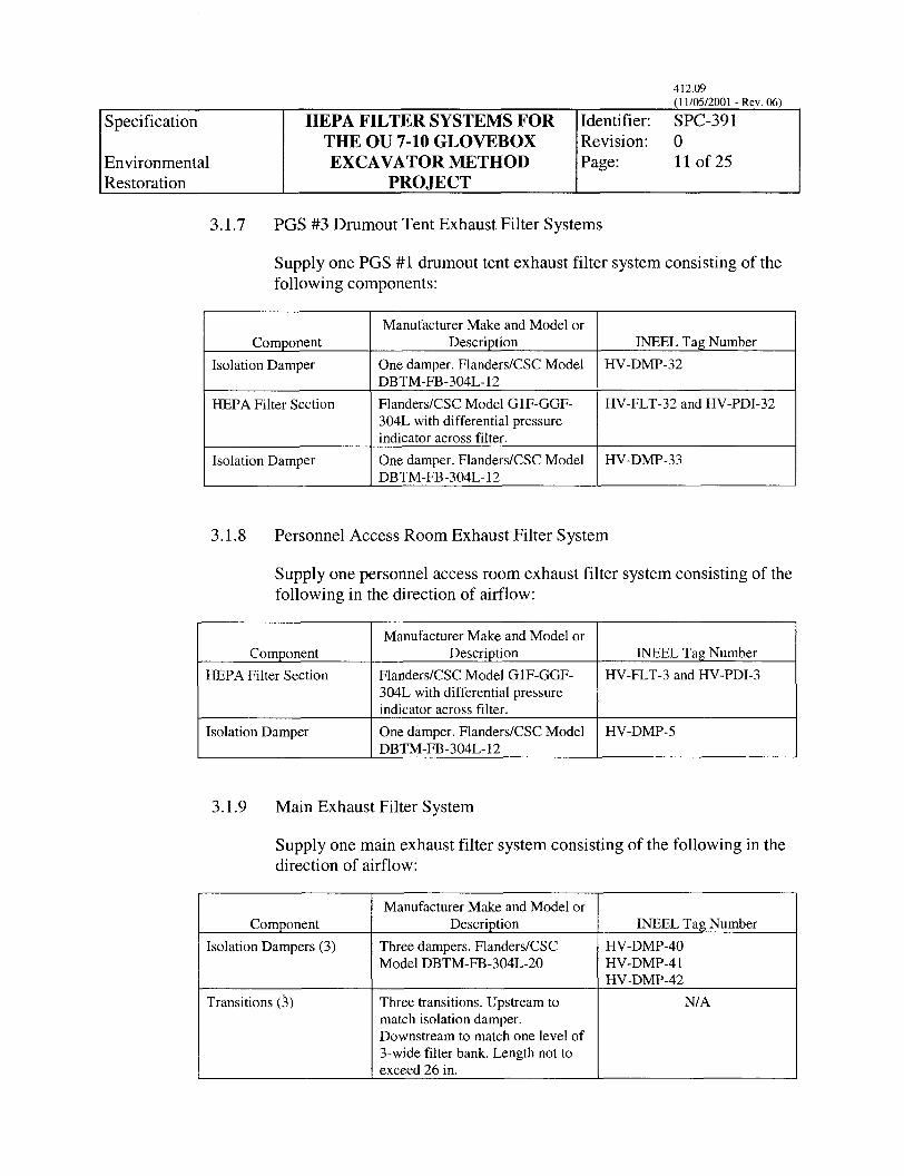
3.1.7 PGS #3 Drumout Tent Exhaust Filter Systems
Identifier: SPC-391 Revision: 0 Page: 11 of 25
Supply one PGS #1 drumout tent exhaust filter system consisting of the following components:
Component Isolation Damper
HEPA Filter Section
Isolation Damper
Manufacturer Make and Model or
One damper. FlanderdCSC Model HV-DMP-32
FlanderdCSC Model G1F-GGF- 304L with differential pressure indicator across filter. One damper. FlandedCSC Model HV-DMP-33
Description INEEL Tag Number
DBTM-FB-304L- 12 HV-FLT-32 and HV-PDI-32
DBTM-FB-304L- 12
3.1.8 Personnel Access Room Exhaust Filter System
Component HEPA Filter Section
Isolation Damper
Supply one personnel access room exhaust filter system consisting of the following in the direction of airflow:
Manufacturer Make and Model or
FlandersKSC Model GlF-GGF- 304L with differential pressure indicator across filter. One damper. FlandersKSC Model HV-DMP-5
Description INEEL Tag Number HV-FLT-3 and HV-PDI-3
DBTM-FB-304L- 12
3.1.9 Main Exhaust Filter System
Supply one main exhaust filter system consisting of the following in the direction of airflow:
ComDonent Isolation Dampers (3)
Transitions (3)
Manufacturer Make and Model or Description
Three dampers. FlanderdCSC Model DBTM-FB-304L-20 ~~ ~
Three transitions. Upstream to match isolation damper. Downstream to match one level of 3-wide filter bank. Length not to exceed 26 in.
INEEL Tag Number HV-DMP-40 HV-DMP-4 1 HV-DMP-42
N/A
Specification
Environmental Restoration
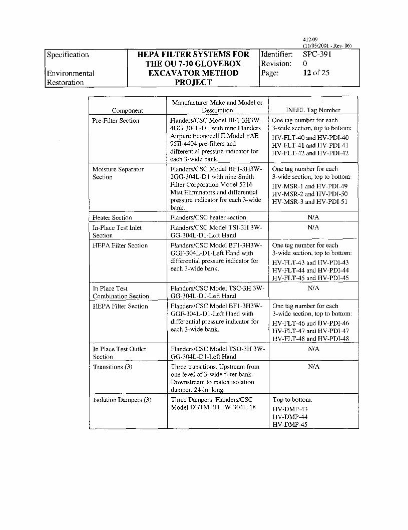
Component Pre-Filter Section
HEPA FILTER SYSTEMS FOR
EXCAVATOR METHOD PROJECT
THE OU 7-10 GLOVEBOX
Moisture Separator Section
Manufacturer Make and Model or Description
Flanders/CSC Model BF1-3H3W- 4GG-304L-D1 with nine Flanders Airpure Econocell 11 Model FAE 9511-4404 pre-filters and differential pressure indicator for each 3-wide bank. Flanders/CSC Model BFl-3H3W- 2GG-304L-D1 with nine Smith Filter Corporation Model 5216 Mist Eliminators and differential pressure indicator for each 3-wide bank. FlandersKSC heater section. Heater Section
In-Place Test Inlet Section
INEEL Tag Number One tag number for each 3-wide section, top to bottom: HV-ET-~O and H V - P D I ~ O HV-FLT-41 and HV-PDI-4 1 HV-FLT-42 and HV-pDI-42
One tag number for each 3-wide section, top to bottom: HV-MSR- 1 and HV-PDI-49 HV-MSR-2 and HV-pDI-50 HV-MSR-3 and HV-pDI-5 1
N/A
HEPA Filter Section
Flanders/CSC Model TSI-3H 3W- GG-304L-D 1 -Left Hand Flanders/CSC Model BF1-3H3W- GGF-304L-Dl-Left Hand with differential pressure indicator for each 3-wide bank.
FlandedCSC Model TSC-3H 3W- GG-304L-D I-Left Hand FlandersKSC Model BF1-3H3W- GGF-304L-Dl-Left Hand with differential pressure indicator for each 3-wide bank.
Flanders/CSC Model TSO-3H 3W- GG-304L-Dl-Left Hand Three transitions. Upstream from one level of 3-wide filter bank. Downstream to match isolation damper. 24-in. long. Three Dampers. Flanders/CSC Model DBTM- IH 1 W-304L- 18
In Place Test Combination Section HEPA Filter Section
N/A
One tag number for each 3-wide section, top to bottom: HV-FLT-43 and HV-pDI-43 HV-FLT-44 and HV-PDI-44 HV-FLT-45 and HV-PDI-45
N/A
One tag number for each 3-wide section, top to bottom: HV-FLT-46 and HV-PDI-46 HV-FLT-47 and HV-PDI-47 HV-FLT-48 and HV-PDI-48
N/A
N/A
Top to bottom: HV-DMP-43 HV-DMP-44 HV-DMP-45
In Place Test Outlet Section Transitions (3)
Isolation Dampers (3)
412.09 (1 1/05/2001 - Rev. 06)
Identifier: SPC-391 Revision:
12 of 25 I
Specification
Environmental Restoration
3.2 Requirements Applicable to All Equipment
HEPA FILTER SYSTEMS FOR
EXCAVATOR METHOD PROJECT
THE OU 7-10 GLOVEBOX
3.2.1 Design Pressure
412.09 (1 1/05/2001 - Rev. 06)
Identifier: SPC-391 Revision: 0 Page: 13 of 25
All housings shall be adequately reinforced to withstand a negative pressure of 10 inches water gage (iwg) and a positive pressure of +10 iwg. In addition, the main exhaust filter system and components shall be adequately reinforced to withstand a negative pressure of -15 iwg.
3.2.2 Seismic
Each of the filter housing modules shall be seismically qualified based on comparison to previous shake table testing and by analysis. These housing modules shall be qualified in accordance with the criteria of the International Building Code Section 1621, with the value of Fp equal to 0.14 times the weight of the equipment being analyzed. Seismic qualification and design documents shall be submitted prior to award of contract.
3.2.3 Welding
All welding procedures, welders, and welder operators shall be qualified in accordance with American Society of Mechanical Engineers (ASME) Boiler and Pressure Vessel Code, Section IX. All production welds shall be visually inspected per the manufacturer’s standard inspection procedure, which incorporates the workmanship acceptance criteria described in Sections 5 and 6 of American National Standards Institute (ANSI)/American Welding Society (AWS) D9.1.
All pressure-retaining weld joints and seams shall be continuously welded with no pores allowed. Joints and seams requiring only intermittent welds, such as reinforcement members, shall not be continuously welded. As a minimum, joints and seams shall be wire brushed or buffed to remove heat discoloration, burrs, and sharp edges. All weld joints and seams that are a portion of any gasket-sealing surface (e.g., duct connecting flanges) shall be ground smooth and flush with the adjacent base metal.
3.2.4 Materials and Construction
The test housings shall be constructed in accordance with the applicable design parameters of ASME N509.
Specification I Environmental Restoration
THE OU 7-10 GLOVEBOX EXCAVATOR METHOD
PROJECT
412.09 (1 1/05/2001 - Rev. 06)
Identifier: SPC-39 1 Revision: 0 Page: 14 of 25
The in-place test housings, filter housings, prefilter housings, moisture eliminator housings, heater housings, transitions, and isolation dampers shall be manufactured from unpainted Type 304L stainless steel.
The upstream and downstream connection flanges shall be a minimum of 1-1/2 in. wide. Flanges shall be turned to the outside of the air stream to prevent contamination buildup and allow the customer to connect mating ductwork from outside the housing. Flange gaskets shall be l/S-in. neoprene.
Each combined assembly including filter housings and test housings shall be the product of a single manufacturer. The test housings and filter housings shall be welded together in series at the factory to make up a filter train as called out in Section 3.1 of this specification.
Each filter bank assembly shall be supplied with a factory installed 6-in. high structural mounting base. The manufacturer shall provide holes in the mounting base for the purchaser to fasten the assembly to the floor.
Certified mill test reports (CMTRs) shall be submitted for all materials that make up the pressure boundary.
3.3 BF-Series Filter Housings
3.3.1 General
BF Series HEPA filter housing, prefilter housings, and moisture separator housings shall be FlandersICSC Corporation BFl Series bag-inhag-out, side access design, left-hand access. The design and filter arrangement shall be a side-servicing bank that will allow air to enter and exit the housing without changing directions.
The housing shall be a gel seal design, which incorporates a knife-edge that mates into the gel-filled perimeter channel of the face on the filter. Access to the filter shall be on the side of the housing. There shall be a safety feature where the filter-locking arm and access door shall interface in such a manner that minimizes the possibility of the door being closed until the filters are correctly seated in the housing. Prior to leaving the factory, each knife-edge shall be checked with an alignment gage to ensure proper alignment with the filter. The filter-sealing mechanism shall be replaceable and shall be operated through the change-out bag by a locking handle. The mechanism shall exert equal force at the top and
Specification
Environmental Restoration
bottom edge of the filter when engaging or disengaging the filter from the knife-edge.
HEPA FILTER SYSTEMS FOR Identifier: SPC-39 1 THE OU 7-10 GLOVEBOX Revision: 0 EXCAVATOR METHOD Page: 15 of 25
PROJECT
Housings shall be equipped with filter-removal rods to draw the filters to the change-out position. The removal rods shall be operated from inside the change-out bag, and the filters shall be removed by pulling against the bottom of the filter frame. There shall be no penetration through the housing for operation of the removal rod. All change-out operations shall be within the bag so there is a barrier between the worker and the filter at all times.
All hardware on the housing and all mechanical components of the filter-sealing mechanism shall be Type 300 series stainless steel, except for the cast aluminum access doorknobs.
The housings shall have a bagging ring around each filter access port. The bagging ring shall have two continuous ribs to secure the polyvinyl chloride (PVC) change-out bag. The outer edge of the ring shall be hemmed to prevent the bag from tearing. A door having an extruded neoprene gasket that is manually replaceable after the door has been removed shall cover each access port and bagging ring. When closed, the door shall not press against the bag-out port and PVC bag, thereby eliminating the possibility of damage to the bag.
One PVC change-out bag shall be furnished for each filter access port. Each bag shall have its stock number rolled in the hem. The PVC bag material shall be 8 mil thick, yellow in color, with a translucent taffeta texture finish, and shall not stick together. For visibility during change- out, the bag shall include approximately 16 in. of clear PVC at the mouth. Three glove sleeves shall be built into the bag to facilitate handling of the filter during change-out. The PVC bags of this design shall have been tested by an independent laboratory to prove the bat’s operability at extreme temperature ranges of 0 to 130°F. The elastic shock cord shall be hemmed into the mouth of the bag so that it fits securely when stretched around the bagging ring. To prevent the bag from sliding off the bagging ring during change-out operation, one nylon security strap shall be provided with each filter access port. A nylon- cinching strap shall also be provided with each access port to tie off the slack in the bag while the ventilation system is operating.
Static pressure gages shall be factory mounted with associated 300 series stainless steel fittings and tubing to measure differential pressure across each level of 3-wide filter banks. Gages shall be factory mounted in
Specification
Environmental Restoration
412.09 (1 1/05/2001 - Rev. 06)
Identifier: SPC-391 Revision: 0 Page: 16 of 25
HEPA FILTER SYSTEMS FOR
EXCAVATOR METHOD PROJECT
THE OU 7-10 GLOVEBOX
locations easily readable from the floor level in front of the filter access doors. Gages shall be labeled with 300 series stainless steel identification labels stitch-welded to the gage-mounting bracket. Gages shall have range from 0 to 10 iwg. Gages shall have isolation valves on both ports.
A banding kit to facilitate sealing off the bag between the housing and the spend filter shall be supplied with the filter housings. The kit shall contain a supply of 50 stainless steel bands and the tools necessary to perform the banding operation.
A filter removal tray shall be provided for each level of 3-wide filter banks. The filter removal tray shall fit into the standard housing to provide support for the filter that is being changed out, as well as for the rep1 acemen t fi 1 ter .
Moisture drains shall be provided in the moisture separator section. Moisture drains shall include a stainless steel 1/2-in. half-coupling, close nipple, and a stainless steel ball valve with a brass plug.
Lifting lugs shall be installed on the completed filter housings to allow for lifting of the entire assembly. Lugs shall be Type 304L stainless steel and shall be designed to support the assembly with a factor of safety of 3.
Filter access doors shall be left hand when loolung in the direction of airflow from the upstream side of the housing.
3.4 G-Series Filter Housings
G-Series filter housings shall be cylindrical with a lid-type door on the top held in place by tie-down latches. The latches shall be manufactured in such a manner that they pivot away from the bag-out port after release so they do not impede the bag-inhag-out process.
The inlet and outlet connections shall be 12 in. diameter with flanged connections and shall extend 6 in. from the housing wall.
As the air enters the housing, a baffle plate shall turn the air downward. At the point where the air hits the bottom of the housing, the air shall turn upwards and pass through the filter element. After passing through the filter element, the air shall hit the top of the housing and be turned, thus forcing the air out of the filter housing.
412.09 (1 1/05/2001 - Rev. 06)
I Specification I HEPA FILTER SYSTEMS FOR I Identifier: SPC-391
Environmental Restoration
THE OU 7-10 GLOVEBOX Revision: 0 EXCAVATOR METHOD Page: 17 of 25
PROJECT
The housings shall accommodate fluid seal filters. The housings shall incorporate a knife-edge that mates into the fluid-filled perimeter channel on the face of the filter. Access to the filter shall be from the side of the housing. The filter-sealing clamps shall be operated through the change-out bag. Spring-loaded filter clamps on the housing shall secure the filter during operation. The clamps shall be constructed of Type 304L stainless steel with a 3/8-in. stainless steel rod handle. The handle shall turn in only one direction and lock when in the closed position. The mechanisms shall exert equal force on the filter when maintaining the filter on the knife-edge.
All change-out operations shall be within the bag so there is a barrier between the worker and the filter at all times.
The housings shall have a bagging ring around the filter access port. The bagging ring shall have two continuous ribs to secure the PVC change-out bag. The outer edge of the ring shall be hemmed to prevent the bag from tearing. A door having an extruded neoprene gasket that is manually replaceable after the door has been removed shall cover the access port and bagging ring. When closed, the door shall not press against the bag-inhag-out port and PVC bag, thereby eliminating the possibility of the bag being cut by this pressure.
One PVC change-out bag shall be furnished for each filter access port. Each bag shall have its stock number rolled in the hem. The PVC bag material shall be 8 mil thick; amber in color; with a translucent, matte textured finish; and shall not stick together. For visibility during change-out, the bag shall include approximately 12 in. of transparent PVC at the mouth. Three glove sleeves shall be built into the bag to facilitate handling the filter during change-out. A 1/4-in. diameter elastic shock cord shall be hemmed into the mouth of the bag so that it fits securely when stretched around the bagging ring. To prevent the bag from sliding off the bagging ring during the change-out operation, one nylon security strap shall be provided with each filter access port. A cinching strap shall also be provided with each bag-out port to tie off the slack in the bag while the ventilation system is operating.
Static pressure gages shall be factory-mounted with associated 300 series stainless steel fittings and tubing to measure differential pressure across the HEPA filter. Gages shall be factory-mounted in locations easily readable from the floor level in front of the filter access doors. Gages shall be labeled with 300 series stainless steel identification labels stitch-welded to the gage-mounting bracket. Gages shall have range from 0 to 10 iwg. Gages shall have isolation valves on both ports.
Dioctyl phthalate (DOP) test ports shall be installed on the filter inlet and outlet. A DOP injection port (3/4-in. coupling with brass plug) shall be located on the
412.09
Specification
Environmental Restoration
HEPA FILTER SYSTEMS FOR Identifier: SPC-391
EXCAVATOR METHOD Page: 18 of 25 THE OU 7-10 GLOVEBOX Revision: 0
PROJECT
inlet side of the housing. Sample ports (3/8-in. couplings with brass plugs) shall be located upstream and downstream of the filter in the inlet and outlet connections.
Inlet and outlet connections shall be 304L stainless steel flanges, at least 1-1/2 in. wide, for connection to upstream and downstream ductwork. Flanges shall not be drilled.
Housings shall be mounted on a steel frame stand to hold the filter housing 6 in. above the floor level. Stand and housing shall meet seismic qualifications detailed in the seismic section of this specification.
3.5 Heater Sections
The heater sections shall be designed and installed in accordance with National Fire Protection Association (NFPA) 90B, “Standard for the Installation of Warm Air Heating and Air-conditioning Systems.” This includes, but is not limited to, ensuring minimum required clearances are provided and temperature limit controls are installed to de-energize the heater section if downstream temperatures exceed 200°F. The temperature controls shall be UL listed, such that they cannot be set higher than a specified temperature setting, and located no more than 2 ft (0.61 m) downstream from the heat exchanger.
Each 3-wide section of the RCS exhaust housing shall have a 3-kW heating element. The heating elements shall be controlled with a humidistat sensing humidity in the corresponding upstream transition section of the housing. Each humidistat shall actuate its corresponding heating element at any time the relative humidity is at or above 90%.
3.6 In-Place DOP Test Sections
3.6.1 General
In-place test housings shall be FlanderdCSC Corporation’s TS-series side service design or approved equal and shall be designed to allow in-place leak testing of HEPA filters in accordance with the applicable sections of ASME N5 10.
All hardware and all mechanical components on the test housings shall be 300 series stainless steel. All ports on the test housings shall be 300 series stainless steel and shall be identified with 300 series stainless steel labels that are welded to the test housing. The test housings shall be constructed in such a manner that adjoining test chambers are isolated
Specification
Environmental Restoration
412.09 ( 1 1/05/2001 - Rev. 06)
Identifier: SPC-391 Revision:
19 of 25
HEPA FILTER SYSTEMS FOR
EXCAVATOR METHOD PROJECT
THE OU 7-10 GLOVEBOX
from each other. This shall permit individual efficiency testing of each HEPA filter and its frame per ASME N5 10.
All filter testing shall be conducted from a location outside the containment filtration system and shall not require the testing personnel to enter into the system. All test ports on the test housing shall be located on the same side as the HEPA filter access doors.
Upstream and downstream test chambers shall contain identical devices to mix and disperse a uniform aerosol challenge ahead of the filter as well as the effluent of the filter being tested. Challenge aerosol inlet ports and upstream and downstream sample ports shall be provided for each filter position.
The mixing devices shall be designed and constructed to swing away when not in the test mode. Stationary or rotatable baffle type test housings will not be acceptable.
The in-place test housings shall be sized to mate with the HEPA filter housings specified herein. The final containment filtration system shall be completely fabricated, assembled, tested, and cleaned at the manufacturer’s facility. Subassemblies from outside sources will not be acceptable.
Test sections shall incorporate the following design features and capabilities:
1. Swing-aside mixing devices
2. Air-aerosol uniformity with the mixing device in the test position
3. Detection of a leak in a filter
4. Detection of a leaking filter that may escape detection when tested by a conventional in-place leak test
5 . Each filter can be leak-tested individually
6. Maximum pressure drop of 0.5 iwg at 1,000 cfm per filter, when the mixing device is in the test position.
All test sections shall be left hand when looking in the direction of aifflow from the upstream side of the housing.

Specification
Environmental Restoration
3.6.2 Test Inlet Sections
HEPA FILTER SYSTEMS FOR Identifier: SPC-391
EXCAVATOR METHOD Page: 20 of 25 THE OU 7-10 GLOWBOX Revision: 0
PROJECT
The test inlet section design shall allow for injection of challenge aerosol or vapor upstream of each HEPA filter. It shall adequately mix the challenge with the air stream. It shall provide upstream sampling of the aerosol in front of each HEPA filter. Maximum depth in direction of airflow for the test inlet section shall be 28 in.
3.6.3 Test Combination Sections
The test inlet section design shall allow for injection of challenge aerosol or vapor upstream of each HEPA filter. It shall adequately mix the challenge with the air stream. It shall provide upstream sampling of the aerosol in front of each HEPA filter. Maximum depth in direction of airflow for the test inlet section shall be 28 in.
3.6.4 Test Outlet Sections
The test outlet sections shall provide for single point downstream sampling of the penetrant behind each HEPA filter in the bank. The depth in direction of airflow for the test outlet section shall be 24 in.
3.7 Isolation Dampers
3.7.1 Dampers
Isolation dampers shall have 1-1/2-in. flanges. Flanges shall be factory-drilled with 7/16-in. diameter holes not more than 4 in. apart. The frame material shall be unpainted 304L stainless steel, with 300 series stainless steel linkage components. Shafts shall be a 3/4-in. diameter stainless steel rod with shaft seals.
Dampers shall be positive seal, isolation type that shall be bubble-tight at a differential pressure of 10 iwg. Dampers shall be constructed with a 304L stainless steel blade. The damper shall be all welded design.
3.7.2 Actuators
Manual actuators shall be 1/4 turn-worm-geared actuators with hand wheel. Actuator shall have an aluminum base and cover. Rated output torque shall be not less than 2,000 inch-pounds or that required to actuate the damper. Gear ratio shall be 30: 1 minimum. Actuator shall be fully lubricated and self-loclung to hold in any position. Actuator shall be capable of being locked in position for safety.

Specification
Environmental Restoration
3.8 Transitions
HEPA FILTER SYSTEMS FOR Identifier: SPC-391
EXCAVATOR METHOD Page: 21 of 25 THE OU 7-10 GLOVEBOX Revision: 0
PROJECT
Transitions shall be welded on the filter bank side and flanged on the isolation damper side. Flanges shall be minimum 1-1/2 in. wide all around and shall be sized to match the isolation damper to which they will be connected. Flanges shall be drilled to match their respective isolation damper hole pattern.
4. QUALITY ASSURANCE
4.1 Minimum Qualifications of Manufacturer, Supplier, or Personnel
The manufacturer of equipment supplied under this specification shall have successfully manufactured equipment and systems similar to those specified, and those systems shall be operational in successful service in nuclear air-cleaning applications. The manufacturer shall submit upon request references for successful operation of such equipment and systems.
All welding procedures, welders, and welder operators shall be qualified in accordance with ASME Boiler and Pressure Vessel Code, Section IX.
4.2 Quality Assurance Program
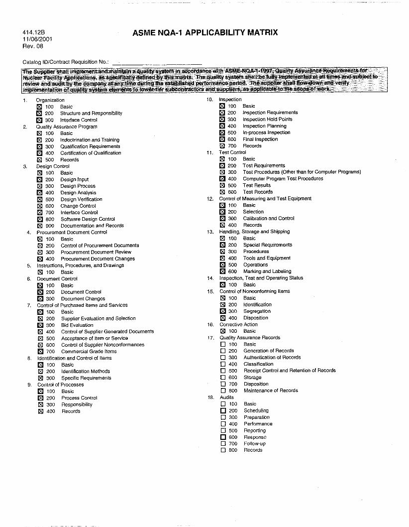
Each of the items specified herein shall be manufactured under a quality assurance program that meets the requirements of ASME NQA-1. The manufacturer shall submit documented evidence that they have been independently audited by customers at least 3 times within the last 6 years to ASME NQA-1 requirements and have successfully passed all three audits. The INEEL Form 414.12B (Attachment 1) summarizes the ASME NQA-1 requirements applicability.
4.3 Nondestructive Examination
All production welds shall be visually inspected per the manufacturer’s standard inspection procedure, which incorporates the workmanship acceptance criteria described in Sections 5 and 6 of ANSVAWS D9.1.
4.4 Operational Testing
The HEPA filter sealing surfaces and each of the completed assembly pressure boundaries shall be leak-tested by the “Pressure Decay Method,” in accordance with ASME N510 Paragraphs 6 and 7. Pressure readings shall be recorded once a
Specification
Environmental Restoration
412.09 (1 1/05/2001 - Rev. 06)
Identifier: SPC-391 Revision: 0 Page: 22 of 25
HEPA FILTER SYSTEMS FOR
EXCAVATOR METHOD PROJECT
THE OU 7-10 GLOVEBOX
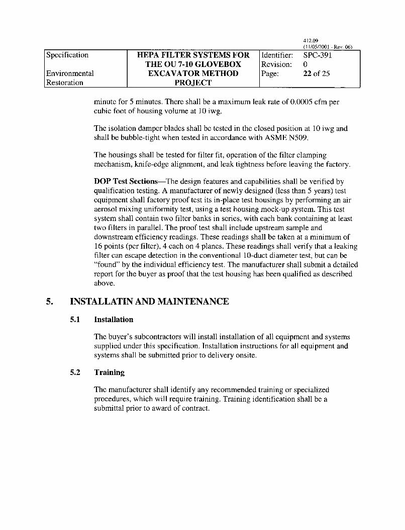
minute for 5 minutes. There shall be a maximum leak rate of 0.0005 cfm per cubic foot of housing volume at 10 iwg.
The isolation damper blades shall be tested in the closed position at 10 iwg and shall be bubble-tight when tested in accordance with ASME N509.
The housings shall be tested for filter fit, operation of the filter clamping mechanism, knife-edge alignment, and leak tightness before leaving the factory.
DOP Test Sections-The design features and capabilities shall be verified by qualification testing. A manufacturer of newly designed (less than 5 years) test equipment shall factory proof test its in-place test housings by performing an air aerosol mixing uniformity test, using a test housing mock-up system. This test system shall contain two filter banks in series, with each bank containing at least two filters in parallel. The proof test shall include upstream sample and downstream efficiency readings. These readings shall be taken at a minimum of 16 points (per filter), 4 each on 4 planes. These readings shall verify that a lealung filter can escape detection in the conventional 10-duct diameter test, but can be “found’ by the individual efficiency test. The manufacturer shall submit a detailed report for the buyer as proof that the test housing has been qualified as described above.
5. INSTALLATIN AND MAINTENANCE
5.1 Installation
The buyer’s subcontractors will install installation of all equipment and systems supplied under this specification. Installation instructions for all equipment and systems shall be submitted prior to delivery onsite.
5.2 Training
The manufacturer shall identify any recommended training or specialized procedures, which will require training. Training identification shall be a submittal prior to award of contract.
Specification
Environmental Restoration
412.09 (1 1/05/2001 - Rev. 06)
Identifier: SPC-391 Revision:
23 of 25
HEPA FILTER SYSTEMS FOR
EXCAVATOR METHOD PROJECT
THE OU 7-10 GLOVEBOX
5.3 Maintenance
Operation and maintenance of the systems shall be described in the operation and maintenance manuals, which shall be submitted to the buyer prior to shipment of equipment and systems onsite.
6. SUBMITTALS
6.1
6.2
6.3
6.4
General Submittal Requirements
Submit the following general submittals for review by the buyer prior to award of contract:
0
0 , Quality Assurance Program documentation
0 Recommended training.
Submit the following general submittal for review by the buyer prior to shipment of equipment and systems onsite:
0 Installation instructions.
Design Submittal
Submit the following design submittal for review by the buyer prior to shipment of materials or equipment:
0 Seismic Qualification and Design.
Materials Submittal
Submit the following materials submittal for review by the buyer prior to shipment of materials or equipment:
0 Pressure Boundary Material CMTRs.
Construction Submittal
Submit the following construction submittal for review by the buyer prior to shipment of materials or equipment.
0 Weld inspection documentation.
References for successful equipment and systems
Specification
Environmental Restoration
6.5 Test Submittals
HEPA FILTER SYSTEMS FOR
EXCAVATOR METHOD PROJECT
THE OU 7-10 GLOVEBOX
6.5.1 Test Procedures
412.0 (11/05/2001 -Rev. 06)
Identifier: SPC-391 Revision:
24 of 25
Submit the following test procedure submittals for review by the buyer prior to testing:
0 Filter Sealing Surface Tests
0 Pressure Boundary Leak Tests
0 Filter Fit Test
0 DOP Test Sections Qualification Testing.
6.5.2 Test Reports
Submit the following test report submittals for review by the buyer following testing and prior to shipment of materials or equipment:
a Filter Sealing Surface Tests
a Pressure Boundary Leak Tests
a Filter Fit Tests
0 DOP Test Sections Qualification Testing.
6.6 Operating and Maintenance Manuals
Submit the following operating and maintenance (O&M) manuals prior to contract closure:
0 BG-Series Bag-In/Bag-Out Manuals
0 G-Series Bag-In/Bag-Out Manuals
0
0 Damper O&M Manuals
Pre-Filter and Mist Eliminator O&M Manuals
0 Heater Section O&M Manuals.

Specification HEPA FILTER SYSTEMS FOR
Environmental EXCAVATOR METHOD Restoration PROJECT
THE OU 7-10 GLOVEBOX
7. PACKAGING AND SHIPPING
Identifier: SPC-391 Revision: 0 Page: 25 of 25
The manufacturer shall package and ship all materials and systems supplied under this specification in accordance with their packaging and shipping requirements. The manufacturer shall be responsible for all equipment and systems packaging and shipping to the INEEL, as described in the procurement documents.
8. MARKING AND IDENTIFICATION
The system supplier shall identify each component supplied under this specification that has an INEEL Tag Number identified in Section 3.1 of this specification. Identification marking shall be easily readable from the floor level for all components and shall be on stainless steel tags attached to the component.
Packaging for shipment of all equipment and systems shall be clearly marked with the following information:
0 Project: OU 7-10 Glovebox Excavator Method
0 System: HEPA Filter Systems
0 Manufacturer
0 Equipment Enclosed.
9. ACCEPTANCE
9.1 Final Acceptance Method
Final acceptance of equipment and systems supplied under this specification will be contingent upon receipt of all required submittals, equipment, and systems. Equipment and systems will be receipt inspected at the INEEL for compliance to this specification and references herein.
9.2 INEEL Surveillance and Audits
The INEEL personnel shall be allowed access to the manufacturer’s facilities for surveillance and audits of the quality assurance program, materials, fabrication, testing, and preparation for shipping.
10. ATTACHEMENTS
Attachment 1: INEEL Form 414.12B - ASME NQA-1 Applicability Matrix
41 4.12B 1 1 /06/2001 Rev. 08
ASME NQA-1 APPLICABILITY MATRIX
Catalog ID/Contract Requisition No.:
1. Organization 100 Basic 200 Structure and Responsibility 300 Interface Control
2. Quality Assurance Program Ixi 100 Basic Ix) 200 Indoctrination and Training
300 Quatiiication Requirements 400 Certification of Qualification 500 Records
100 Basic 3. Design Control
200 Design Input IE] 300 Design Process
400 Design Analysis 500 Design Verification
IXI 600 Changecontrol 700 Interface Control 800 Software Design Control
IXI 900 Documentation and Records
IXI 100 Basic 4. Procurement Document Control
200 Control of Procurement Documents 300 Procurement Document Review 400 Procurement Document Changes
(x1 100 Basic
100 Basic 200 Document Control 300 Document Changes
Control of Purchased Items and Services 100 Basic
300 Bid Evaluation
5. Instructions, Procedures, and Drawings
6. Document Control
7.
200 Supplier Evaluation and Selection
400 500
IXI 600 700 Commercial Grade Items
8. Identification and Control of Items 100 Basic 200 Identification Methods
IXI 300 Specific Requirements 9. Control of Processes
100 Basic 200 Process Control
IXI 300 Responsibility Ix] 400 Records
Control of Supplier Generated Documents Acceptance of Item or Service Control of Supplier Nonconformances
10.
11.
12.
13.
14.
15.
16.
17.
18.
Inspection 100 Basic 200 Inspection Requirements 300 Inspection Hold Points 400 Inspection Planning 500 In-process Inspection 600 Final Inspection
Test Control IXI 100 Basic
200 Test Requirements IXI 300
400
700 Records
Test Procedures (Other than for Computer Programs) Computer Program Test Procedures
500 Test Results 600 TesiRecords
Control of Measuring and Test Equipment 100 Basic 200 Selection 300 Calibration and Control
(XI 400 Records Handling, Storage and Shipping (x1 100 Basic
200 Special Requirements IXI 300 Procedures
400 Tools and Equipment 500 Operations 600 Marking and Labeling
Inspection, Test and Operating Status 100 Basic
Control of Nonconforming Items p4 100 Basic IXI 200 Identification
300 Segregaiion 400 Disposition
Corrective Action IXI 100 Basic Quality Assurance Records c] 100 Basic c] 200 Generation of Records c] 300 Authentication of Records [ZI 400 Classification c] 500 c] 600 Storage [ZI 700 Disposition Iz] 800 Maintenance of Records Audits Iz] 100 Basic
200 Scheduling Iz] 300 Preparation c] 400 Performance Iz] 500 Reporting
600 Response
(7 800 Records
Receipt Control and Retention of Records
c] 700 FoIIow-UP