Embed Size (px)
Citation preview

Version 3.4 Page 1 of 16
Periodic inspection
and testing
Users guide

Version 3.4 Page 2 of 16
Version 3.4 Page 3 of 16
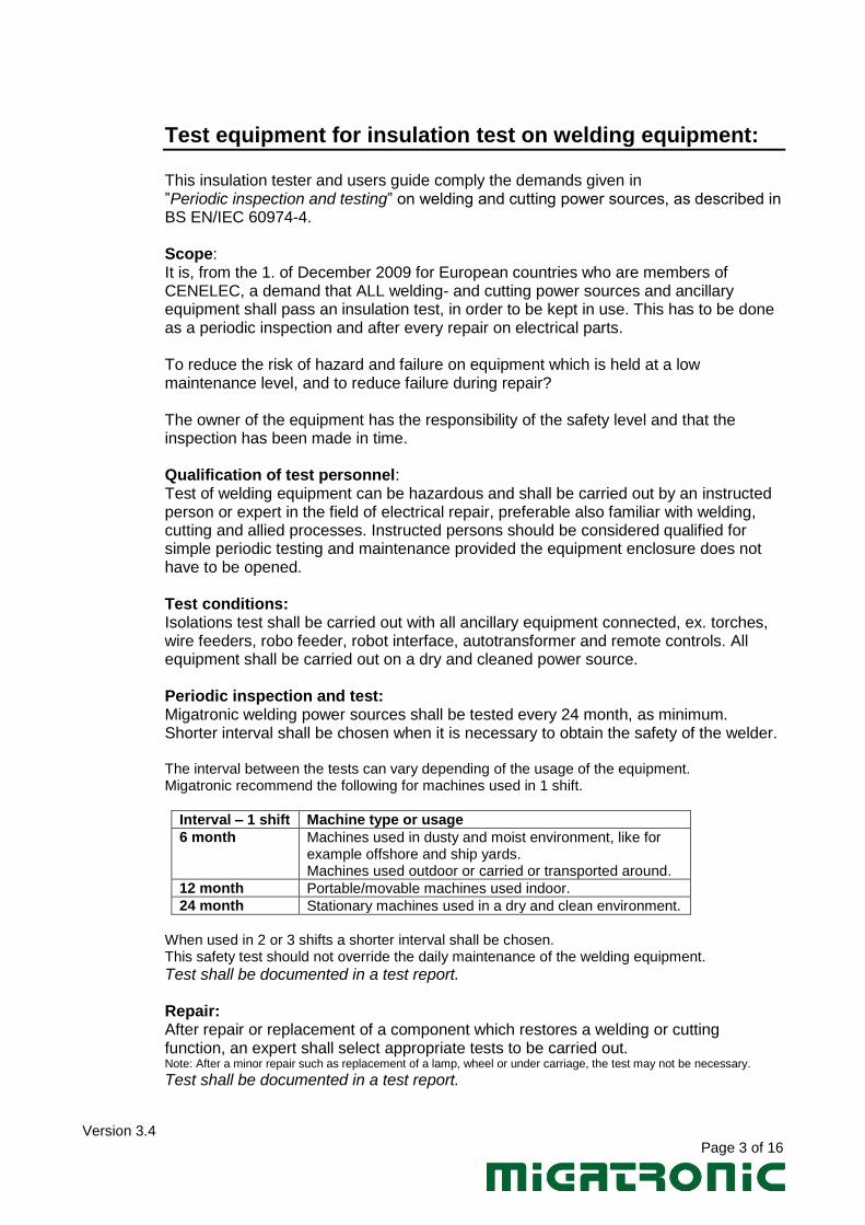
Test equipment for insulation test on welding equipment: This insulation tester and users guide comply the demands given in ”Periodic inspection and testing” on welding and cutting power sources, as described in BS EN/IEC 60974-4. Scope: It is, from the 1. of December 2009 for European countries who are members of CENELEC, a demand that ALL welding- and cutting power sources and ancillary equipment shall pass an insulation test, in order to be kept in use. This has to be done as a periodic inspection and after every repair on electrical parts. To reduce the risk of hazard and failure on equipment which is held at a low maintenance level, and to reduce failure during repair? The owner of the equipment has the responsibility of the safety level and that the inspection has been made in time. Qualification of test personnel: Test of welding equipment can be hazardous and shall be carried out by an instructed person or expert in the field of electrical repair, preferable also familiar with welding, cutting and allied processes. Instructed persons should be considered qualified for simple periodic testing and maintenance provided the equipment enclosure does not have to be opened. Test conditions: Isolations test shall be carried out with all ancillary equipment connected, ex. torches, wire feeders, robo feeder, robot interface, autotransformer and remote controls. All equipment shall be carried out on a dry and cleaned power source. Periodic inspection and test: Migatronic welding power sources shall be tested every 24 month, as minimum. Shorter interval shall be chosen when it is necessary to obtain the safety of the welder. The interval between the tests can vary depending of the usage of the equipment. Migatronic recommend the following for machines used in 1 shift.
Interval – 1 shift Machine type or usage
6 month Machines used in dusty and moist environment, like for example offshore and ship yards. Machines used outdoor or carried or transported around.
12 month Portable/movable machines used indoor.
24 month Stationary machines used in a dry and clean environment.
When used in 2 or 3 shifts a shorter interval shall be chosen. This safety test should not override the daily maintenance of the welding equipment.
Test shall be documented in a test report. Repair: After repair or replacement of a component which restores a welding or cutting function, an expert shall select appropriate tests to be carried out. Note: After a minor repair such as replacement of a lamp, wheel or under carriage, the test may not be necessary.
Test shall be documented in a test report.
Version 3.4 Page 4 of 16
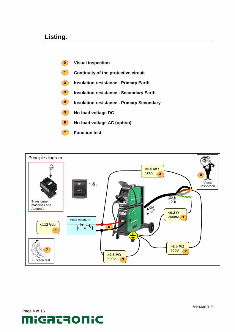
Listing. Visual inspection Continuity of the protective circuit Insulation resistance - Primary Earth Insulation resistance - Secondary Earth Insulation resistance - Primary Secondary No-load voltage DC No-load voltage AC (option) Function test
Principle diagram
Peak measure
>5.0 M
500V
>2.5 M
500V
>2.5 M
500V
<0.3
200mA
<113 Vdc
1
2
3
4
5
6
Transformer machines and Autotrafo
Visual
inspection
0
Function test
7
0
1
2
3
4
5
7
6
Version 3.4 Page 5 of 16
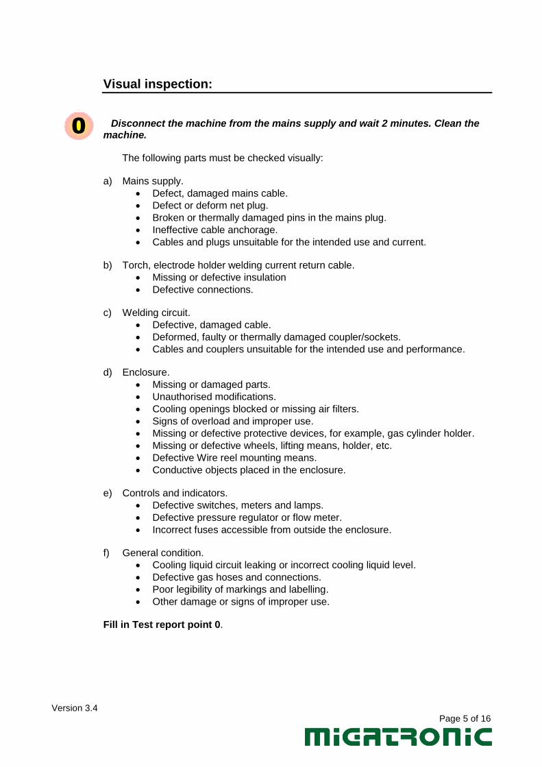
Visual inspection:
Disconnect the machine from the mains supply and wait 2 minutes. Clean the machine.
The following parts must be checked visually:
a) Mains supply.
Defect, damaged mains cable.
Defect or deform net plug.
Broken or thermally damaged pins in the mains plug.
Ineffective cable anchorage.
Cables and plugs unsuitable for the intended use and current.
b) Torch, electrode holder welding current return cable.
Missing or defective insulation
Defective connections.
c) Welding circuit.
Defective, damaged cable.
Deformed, faulty or thermally damaged coupler/sockets.
Cables and couplers unsuitable for the intended use and performance.
d) Enclosure.
Missing or damaged parts.
Unauthorised modifications.
Cooling openings blocked or missing air filters.
Signs of overload and improper use.
Missing or defective protective devices, for example, gas cylinder holder.
Missing or defective wheels, lifting means, holder, etc.
Defective Wire reel mounting means.
Conductive objects placed in the enclosure.
e) Controls and indicators.
Defective switches, meters and lamps.
Defective pressure regulator or flow meter.
Incorrect fuses accessible from outside the enclosure.
f) General condition.
Cooling liquid circuit leaking or incorrect cooling liquid level.
Defective gas hoses and connections.
Poor legibility of markings and labelling.
Other damage or signs of improper use. Fill in Test report point 0.
0
Version 3.4 Page 6 of 16
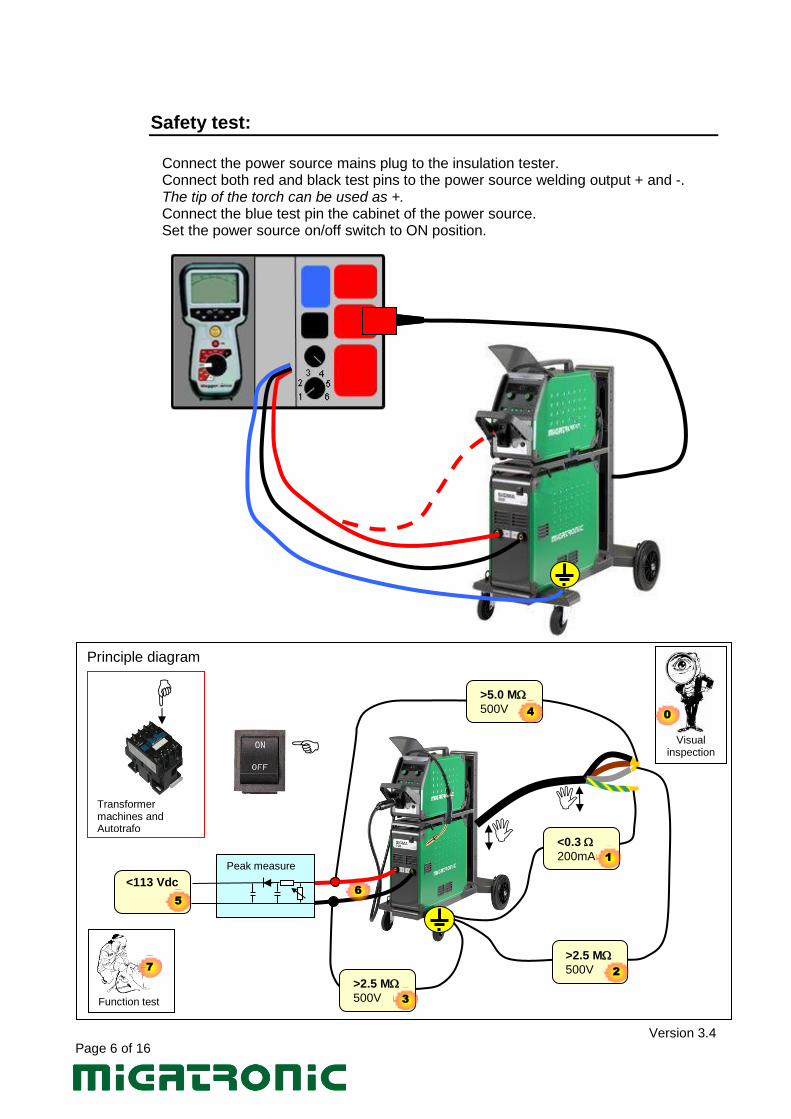
Safety test:
Connect the power source mains plug to the insulation tester. Connect both red and black test pins to the power source welding output + and -. The tip of the torch can be used as +. Connect the blue test pin the cabinet of the power source.
Set the power source on/off switch to ON position.
Principle diagram
Peak measure
>5.0 M
500V
>2.5 M
500V
>2.5 M
500V
<0.3
200mA
<113 Vdc
1
2
3
4
5
6
Transformer machines and Autotrafo
Visual
inspection
0
Function test
7
Version 3.4 Page 7 of 16
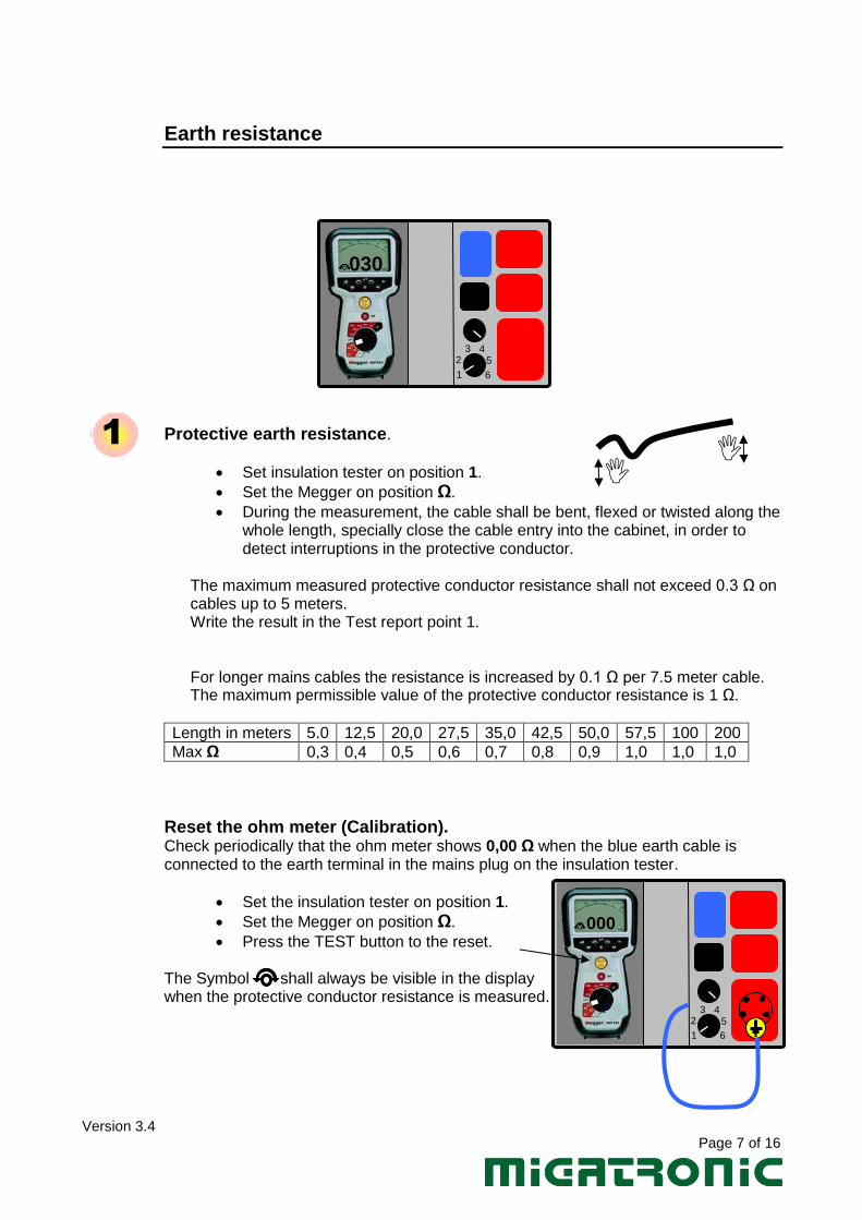
Earth resistance
Protective earth resistance.
Set insulation tester on position 1.
Set the Megger on position Ω.
During the measurement, the cable shall be bent, flexed or twisted along the whole length, specially close the cable entry into the cabinet, in order to detect interruptions in the protective conductor.
The maximum measured protective conductor resistance shall not exceed 0.3 Ω on cables up to 5 meters. Write the result in the Test report point 1. For longer mains cables the resistance is increased by 0.1 Ω per 7.5 meter cable. The maximum permissible value of the protective conductor resistance is 1 Ω.
Length in meters 5.0 12,5 20,0 27,5 35,0 42,5 50,0 57,5 100 200
Max Ω 0,3 0,4 0,5 0,6 0,7 0,8 0,9 1,0 1,0 1,0
Reset the ohm meter (Calibration). Check periodically that the ohm meter shows 0,00 Ω when the blue earth cable is connected to the earth terminal in the mains plug on the insulation tester.
Set the insulation tester on position 1.
Set the Megger on position Ω.
Press the TEST button to the reset.
The Symbol shall always be visible in the display when the protective conductor resistance is measured.
1
1 6
3 4 5 2
1 6
3 4 5 2
030
000
Version 3.4 Page 8 of 16
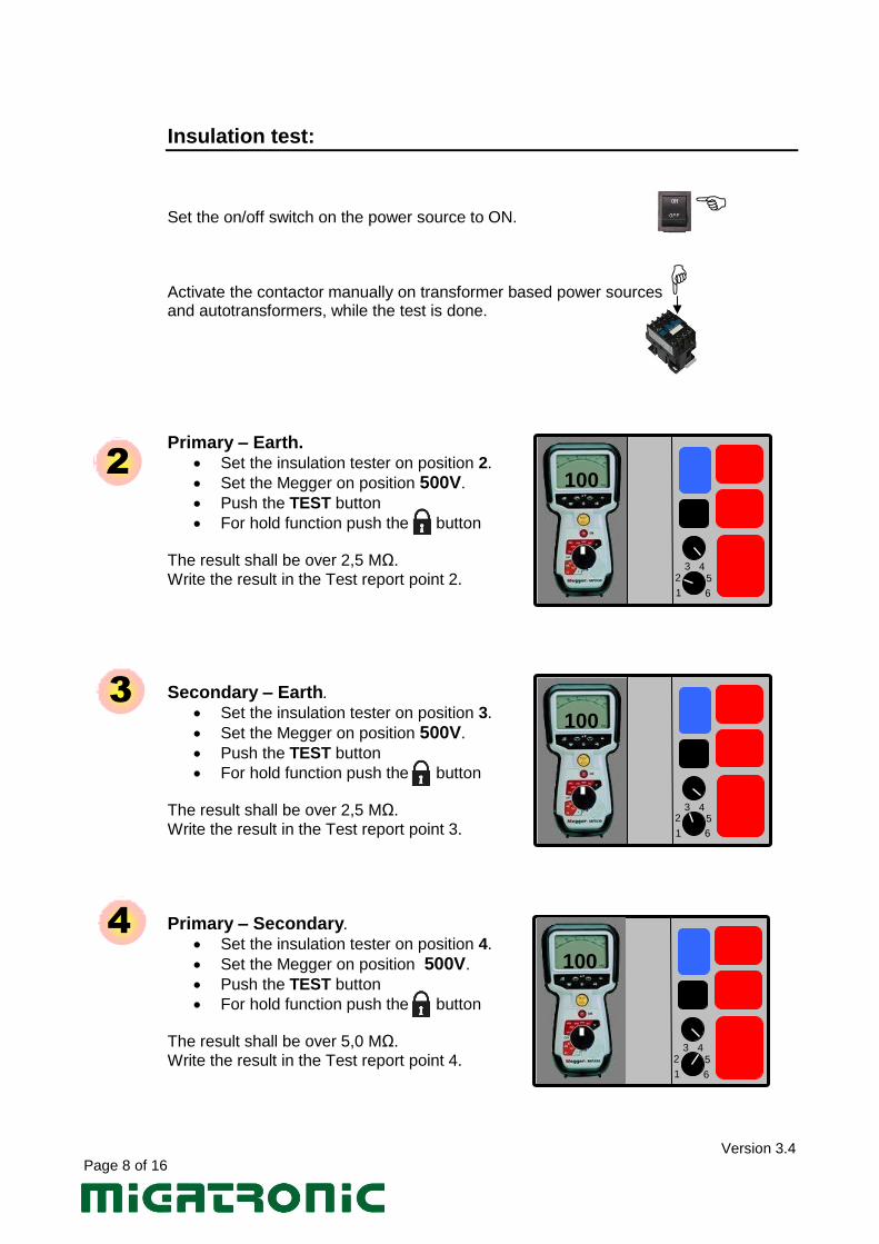
Insulation test: Set the on/off switch on the power source to ON. Activate the contactor manually on transformer based power sources and autotransformers, while the test is done.
Primary – Earth. Set the insulation tester on position 2.
Set the Megger on position 500V.
Push the TEST button
For hold function push the button The result shall be over 2,5 MΩ.
Write the result in the Test report point 2.
Secondary – Earth.
Set the insulation tester on position 3.
Set the Megger on position 500V.
Push the TEST button
For hold function push the button The result shall be over 2,5 MΩ.
Write the result in the Test report point 3.
Primary – Secondary.
Set the insulation tester on position 4.
Set the Megger on position 500V.
Push the TEST button
For hold function push the button
The result shall be over 5,0 MΩ.
Write the result in the Test report point 4.
2
3
4
1 6
3 4 5 2
1 6
3 4 5 2
1 6
3 4 5 2
100
100
100
Version 3.4 Page 9 of 16
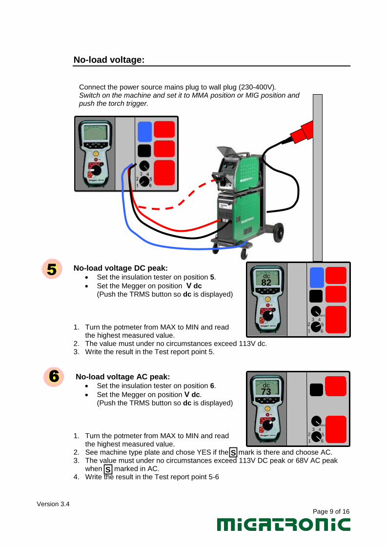
No-load voltage:
Connect the power source mains plug to wall plug (230-400V). Switch on the machine and set it to MMA position or MIG position and push the torch trigger.
No-load voltage DC peak: Set the insulation tester on position 5.
Set the Megger on position V dc (Push the TRMS button so dc is displayed)
1. Turn the potmeter from MAX to MIN and read
the highest measured value. 2. The value must under no circumstances exceed 113V dc. 3. Write the result in the Test report point 5.
No-load voltage AC peak: Set the insulation tester on position 6.
Set the Megger on position V dc. (Push the TRMS button so dc is displayed)
1. Turn the potmeter from MAX to MIN and read the highest measured value.
2. See machine type plate and chose YES if the mark is there and choose AC. 3. The value must under no circumstances exceed 113V DC peak or 68V AC peak
when marked in AC. 4. Write the result in the Test report point 5-6
5
6
1 6
3 4 5 2
MAX
82 dc
1 6
3 4 5 2
MAX
S
S
73 dc
Version 3.4 Page 10 of 16
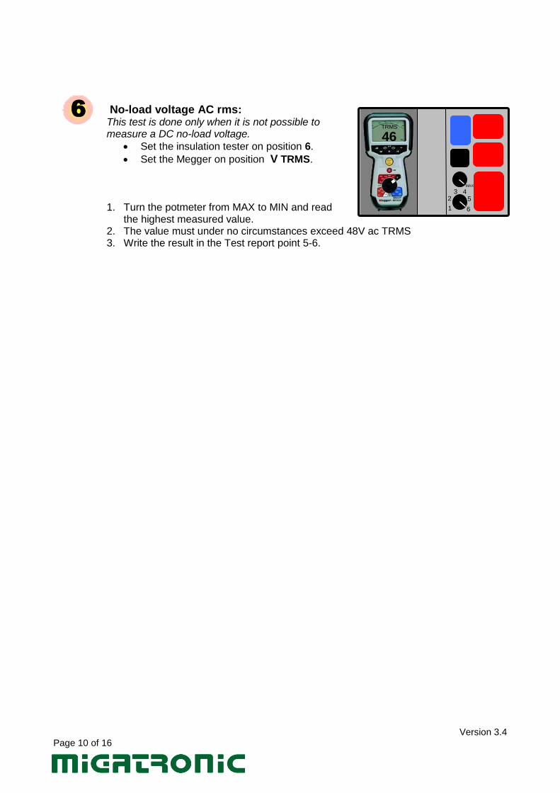
No-load voltage AC rms: This test is done only when it is not possible to measure a DC no-load voltage.
Set the insulation tester on position 6.
Set the Megger on position V TRMS.
1. Turn the potmeter from MAX to MIN and read
the highest measured value. 2. The value must under no circumstances exceed 48V ac TRMS 3. Write the result in the Test report point 5-6.
6
1 6
3 4 5 2
46
MAX
TRMS
Version 3.4 Page 11 of 16
Functional test:
1. Test all the basically welding functions.
2. Tick the Test report point 7.
7
Version 3.4 Page 12 of 16
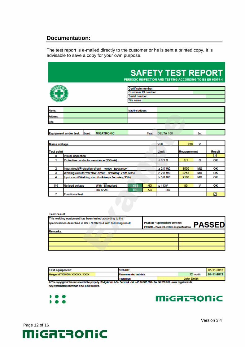
Documentation: The test report is e-mailed directly to the customer or he is sent a printed copy. It is advisable to save a copy for your own purpose.
Version 3.4 Page 13 of 16
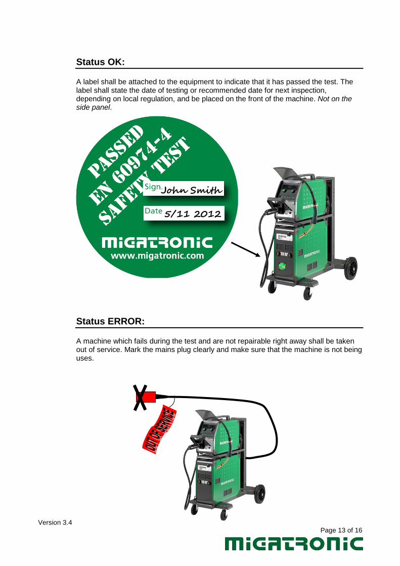
Status OK: A label shall be attached to the equipment to indicate that it has passed the test. The label shall state the date of testing or recommended date for next inspection, depending on local regulation, and be placed on the front of the machine. Not on the side panel.
Status ERROR: A machine which fails during the test and are not repairable right away shall be taken out of service. Mark the mains plug clearly and make sure that the machine is not being uses.
John Smith
5/11 2012
Version 3.4 Page 14 of 16
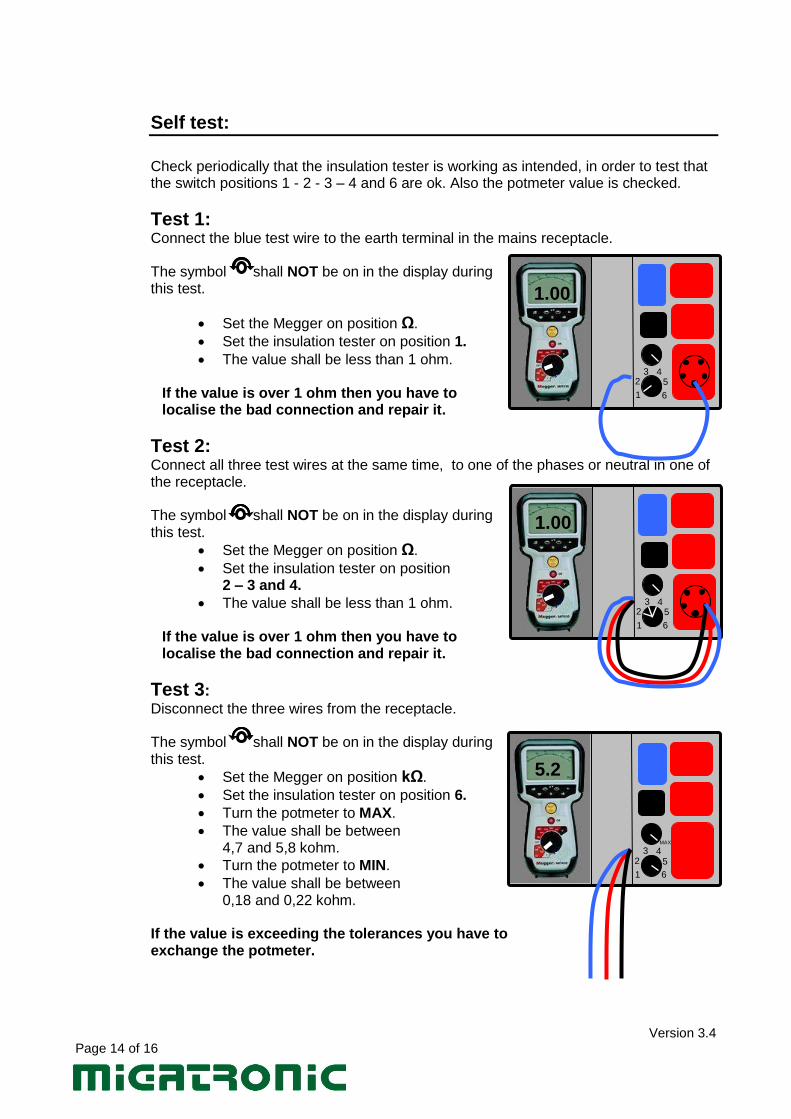
Self test:
Check periodically that the insulation tester is working as intended, in order to test that the switch positions 1 - 2 - 3 – 4 and 6 are ok. Also the potmeter value is checked.
Test 1: Connect the blue test wire to the earth terminal in the mains receptacle. The symbol shall NOT be on in the display during this test.
Set the Megger on position Ω.
Set the insulation tester on position 1.
The value shall be less than 1 ohm.
If the value is over 1 ohm then you have to localise the bad connection and repair it.
Test 2: Connect all three test wires at the same time, to one of the phases or neutral in one of the receptacle. The symbol shall NOT be on in the display during this test.
Set the Megger on position Ω.
Set the insulation tester on position 2 – 3 and 4.
The value shall be less than 1 ohm.
If the value is over 1 ohm then you have to localise the bad connection and repair it.
Test 3: Disconnect the three wires from the receptacle. The symbol shall NOT be on in the display during this test.
Set the Megger on position kΩ.
Set the insulation tester on position 6.
Turn the potmeter to MAX.
The value shall be between 4,7 and 5,8 kohm.
Turn the potmeter to MIN.
The value shall be between 0,18 and 0,22 kohm.
If the value is exceeding the tolerances you have to exchange the potmeter.
1 6
3 4 5 2
MAX
1 6
3 4 5 2
1 6
3 4 5 2
1.00
1.00
5.2
Version 3.4 Page 15 of 16
Non conformances:
On some older machines it can be necessary to do some modifications in order to pass the test. WATER COOLED machines in general: The cooling water can establish an electrically connection between the torch and the cabinet of the machine. Check also that the black water cooling cables made of rubber are not touching any cabinet (earth) potential, because these cables are conductive and may lead to misreading. It is allowed to disconnect water cooling cables and empty the hoses if necessary, when doing the secondary – earth (3) test. LDH. Do not test LDH. LDE TDE 400. Some varistors are placed on the back of the 8 pole remote plug and they are disturbing the test. Measure with 100V and make a note on that in the test report. BDH Disconnect the 3,3uF capacitor that is sitting between output plug + and – to the cabinet, while the test is done. This type of capacitors can only withstand 250V and they will disturb the secondary-earth measurement (3). BDH 320 Preferable – Do not test or at least on 100V. Disconnect the plug for the flow control PCB 71616511. The transistor on the PCB has electrically contact to the cooling water and it will disturb the secondary-earth measurement (3). KT140 I can be necessary to disconnect the 1M ohm resistor between welding + and cabinet in order the get the test through secondary – earth (3) test. Check also that the insulation bushes on the bottom of KT140 are ok. Pilot 1500 Do not test or at least on 100V only. PDX and Zeta The no-load voltage test is not required for plasma cutting power sources.

Version 3.4 Page 16 of 16
Notes: