Embed Size (px)
Citation preview
UNIT IV PERMANENT MAGNET MOTORS
4.1 INTRODUCTION
The use of permanent magnets in construction of electrical machines brings the following benefits
• No electrical energy is absorbed by the field excitation system and thus there is no excitation loss
which means substantial increase in the efficiency.
• Higher torque and/or output power per volume than when using electromagnetic excitation.
• Better dynamic performance than motors with electromagnetic excitation.
• Simplification of construction and maintenance
• Reduction of prices for some types of machines
4.2 PERMANENT MAGNET MATERIALS
There are three classes of permanent magnets currently used for electric motors
• Alnicos (Al, Ni, Co, Fe);
• Ceramics (Ferrites) e.g. Barium ferrite BaO x 6Fe2O3 and Strontium ferrite SrO x 6Fe2O3.
• Rare earth materials i.e. Samarium cobalt SmCo and neodymium iron boron NdFeB.
4.3 TYPES OF PERMANENT MAGNET MOTORS DRIVES
There are three types of permanent magnet motor electromechanical drives they are
• DC Commutator motor drives.
• Brushless motor drives.
� Square Wave Permanent magnet brushless motor drives (also called as PMBLDC).
� Sine Wave Permanent magnet brushless motor drives (also called as PMSM).
• Stepping motor drives.
4.4 APPLICATION OF PERMANENT MAGNET MOTORS
Permanent magnet motors are used in broad range from mW’s to hundreds of KW’s. There are also
attempts to apply PMs to large motors rated at minimum 1 MW. The application of PM electric motor
includes.
� Industrial drives (e.g.) Pumps, Fans , blowers, compressors etc
� Air-conditioning systems, Auto bank machines, Ticketing machines, Bar-code readers at
supermarkets etc.
� Washing machines and cloth dryers, Vacuum cleaners, toys etc.
4.5 SQUARE WAVE PM BRUSHLESS MOTOR DRIVES (BLDC MOTORS)
4.5.1 Why brushless D.C.?
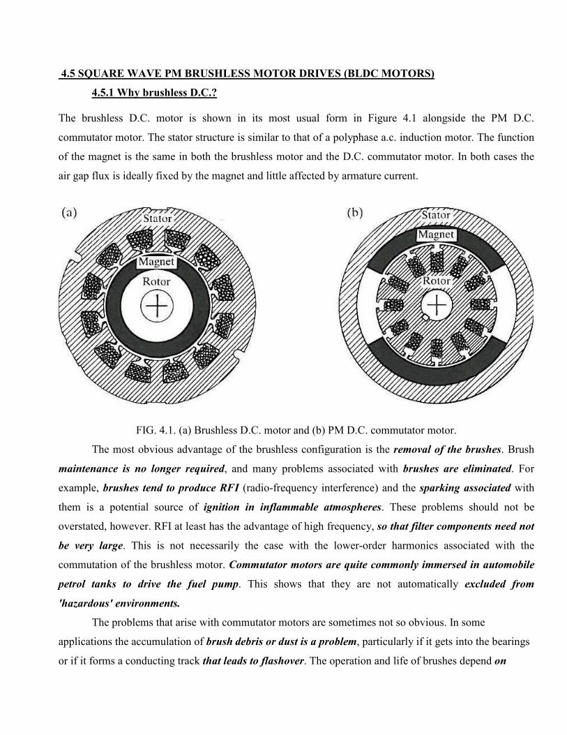
The brushless D.C. motor is shown in its most usual form in Figure 4.1 alongside the PM D.C.
commutator motor. The stator structure is similar to that of a polyphase a.c. induction motor. The function
of the magnet is the same in both the brushless motor and the D.C. commutator motor. In both cases the
air gap flux is ideally fixed by the magnet and little affected by armature current.
FIG. 4.1. (a) Brushless D.C. motor and (b) PM D.C. commutator motor.
The most obvious advantage of the brushless configuration is the removal of the brushes. Brush
maintenance is no longer required, and many problems associated with brushes are eliminated. For
example, brushes tend to produce RFI (radio-frequency interference) and the sparking associated with
them is a potential source of ignition in inflammable atmospheres. These problems should not be
overstated, however. RFI at least has the advantage of high frequency, so that filter components need not
be very large. This is not necessarily the case with the lower-order harmonics associated with the
commutation of the brushless motor. Commutator motors are quite commonly immersed in automobile
petrol tanks to drive the fuel pump. This shows that they are not automatically excluded from
'hazardous' environments.
The problems that arise with commutator motors are sometimes not so obvious. In some
applications the accumulation of brush debris or dust is a problem, particularly if it gets into the bearings
or if it forms a conducting track that leads to flashover. The operation and life of brushes depend on
factors such as atmospheric conditions, which may necessitate the use of different brush grades in the
same motor operating in different climates.
An advantage of the brushless configuration in which the rotor is inside the stator is that more
cross-sectional area is available for the power or 'armature' winding. At the same time the conduction of
heat through the frame is improved. Generally an increase in the electric loading is possible, providing a
greater specific torque. The efficiency is likely to be higher than that of a commutator motor of equal
size, and the absence of brush friction helps further in this regard.
The absence of commutator and brush gear reduces the motor length. This is useful not only as a
simple space saving, but also as a reduction in the length between bearings, so that for a given stack
length the lateral stiffness of the rotor is greater, permitting higher speeds or a longer active
length/diameter ratio. This is important in servo-type drives where a high torque/inertia ratio is required.
The removal of the commutator reduces the inertia still further
The brushless configuration DOES NOT COME WITHOUT SOME DISADVANTAGES. The
two main disadvantages relative to the commutator motor are
(i) The need for shaft position sensing and
(ii) Increased complexity in the electronic controller.
Also, the brushless motor is not necessarily less expensive to manufacture than the commutator
motor, which is perhaps slightly more amenable to automated manufacture.
4.5.2 CONSTRUCTION OF BLDC
STATOR
The stator of a BLDC motor consists of stacked steel laminations with windings placed in the
slots that are axially cut along the inner periphery. Traditionally, the stator resembles that of an
induction motor; however, the windings are distributed in a different manner. Most BLDC motors have
three stator windings connected in star fashion. Each of these windings is constructed with numerous
coils interconnected to form a winding. One or more coils are placed in the slots and they are
interconnected to make a winding. Each of these windings is distributed over the stator periphery to form
an even numbers of poles.
There are two types of stator windings variants: trapezoidal and sinusoidal motors. This
differentiation is made on the basis of the interconnection of coils in the stator windings to give the
different types of back Electromotive Force (EMF). As their names indicate, the trapezoidal motor gives a
back EMF in trapezoidal fashion and the sinusoidal motor’s back EMF is sinusoidal. In addition to the
back EMF, the phase current also has trapezoidal and sinusoidal variations in the respective types of
motor. This makes the torque output by a sinusoidal motor smoother than that of a trapezoidal motor.
However, this comes with an extra cost, as the sinusoidal motors take extra winding interconnections
because of the coils distribution on the stator periphery, thereby increasing the copper intake by the stator
windings.
ROTOR
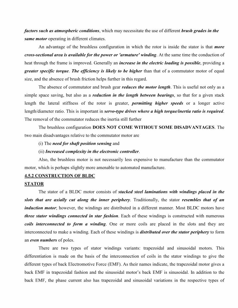
The rotor is made of permanent magnet and can vary from two to eight pole pairs with alternate
North (N) and South (S) poles. Based on the required magnetic field density in the rotor, the proper
magnetic material is chosen to make the rotor. Ferrite magnets are traditionally used to make permanent
magnets. As the technology advances, rare earth alloy magnets are gaining popularity. The ferrite
magnets are less expensive but they have the disadvantage of low flux density for a given volume. In
contrast, the alloy material has high magnetic density per volume and enables the rotor to compress
further for the same torque. Also, these alloy magnets improve the size-to-weight ratio and give higher
torque for the same size motor using ferrite magnets. Neodymium (Nd), Samarium Cobalt (SmCo) and the
alloy of Neodymium, Ferrite and Boron (NdFeB) are some examples of rare earth alloy magnets.
Continuous research is going on to improve the flux density to compress the rotor further. Figure 4.2
shows cross sections of different arrangements of magnets in a rotor.
Fig 4.2 Rotor Magnet Cross Sections
HALL SENSORS
Unlike a brushed DC motor, the commutation of a BLDC motor is controlled electronically. To
rotate the BLDC motor, the stator windings should be energized in a sequence. It is important to know the
rotor position in order to understand which winding will be energized following the energizing sequence.
Rotor position is sensed using Hall effect sensors embedded into the stator. Most BLDC motors have three
Hall sensors embedded into the stator on the non-driving end of the motor. Whenever the rotor magnetic
poles pass near the Hall sensors, they give a high or low signal, indicating the N or S pole is passing near
the sensors. Based on the combination of these three Hall sensor signals, the exact sequence of
commutation can be determined.
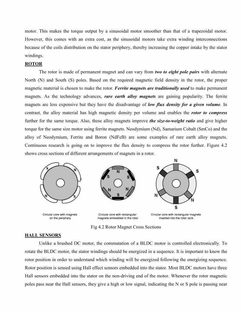
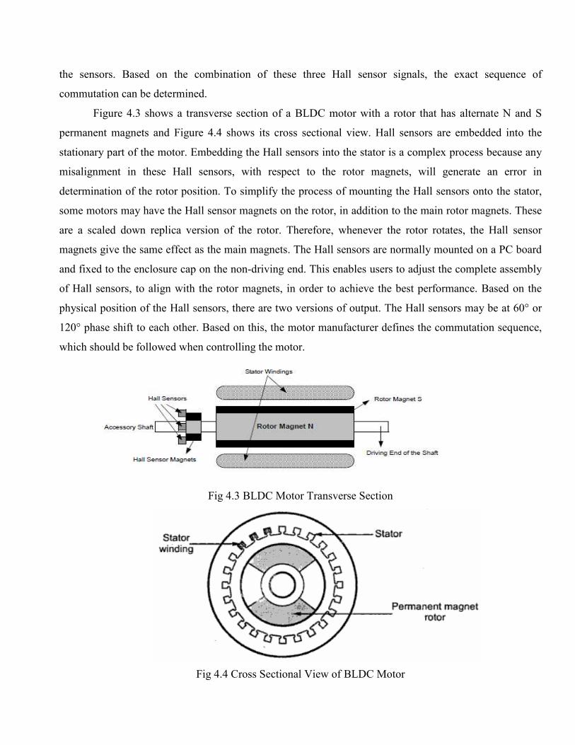
Figure 4.3 shows a transverse section of a BLDC motor with a rotor that has alternate N and S
permanent magnets and Figure 4.4 shows its cross sectional view. Hall sensors are embedded into the
stationary part of the motor. Embedding the Hall sensors into the stator is a complex process because any
misalignment in these Hall sensors, with respect to the rotor magnets, will generate an error in
determination of the rotor position. To simplify the process of mounting the Hall sensors onto the stator,
some motors may have the Hall sensor magnets on the rotor, in addition to the main rotor magnets. These
are a scaled down replica version of the rotor. Therefore, whenever the rotor rotates, the Hall sensor
magnets give the same effect as the main magnets. The Hall sensors are normally mounted on a PC board
and fixed to the enclosure cap on the non-driving end. This enables users to adjust the complete assembly
of Hall sensors, to align with the rotor magnets, in order to achieve the best performance. Based on the
physical position of the Hall sensors, there are two versions of output. The Hall sensors may be at 60° or
120° phase shift to each other. Based on this, the motor manufacturer defines the commutation sequence,
which should be followed when controlling the motor.
Fig 4.3 BLDC Motor Transverse Section
Fig 4.4 Cross Sectional View of BLDC Motor
4.5.3 PRINCIPLE OF OPERATION
The brushless DC motor differs from the normal DC motor in that it employs electrical
commutation of the armature current rather than the mechanical commutation. The word brushless is used
to define the combination of motor, its electronic drive circuit and rotor position sensor. The electronic
drive is an inverter which consists of IGBT’s, which feeds stator windings. The IGBT’s are controlled by
pulses generated by rotor position sensors. This ensures that rotor revolves at angular speed which is equal
to the average speed of the field produced by the stator.
Like a DC motor the driver circuit is fed from a DC supply. The stator and rotor fields remains
stationary with respect to each other at all the speeds. The torque speed characteristic is similar to a DC
motor. The speed can be controlled by controlling the input dc voltage. Because of these similarities and
as it does not have brushes, it is known as brushless DC motor.
There are two types of Brushless DC motor available in practice they are
� Unipolar brushless DC motor
� Bipolar brushless DC Motor.
4.5.3.1 Unipolar Brushless DC motor
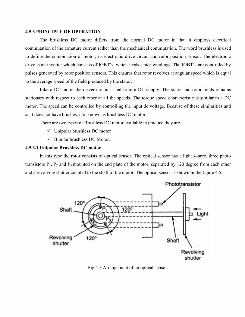
In this type the rotor consists of optical sensor. The optical sensor has a light source, three photo
transistors P1, P2 and P3 mounted on the end plate of the motor, separated by 120 degree from each other
and a revolving shutter coupled to the shaft of the motor. The optical sensor is shown in the figure 4.5.
Fig 4.5 Arrangement of an optical sensor.
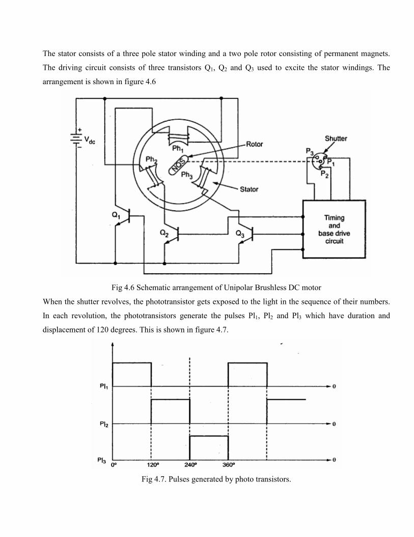
The stator consists of a three pole stator winding and a two pole rotor consisting of permanent magnets.
The driving circuit consists of three transistors Q1, Q2 and Q3 used to excite the stator windings. The
arrangement is shown in figure 4.6
Fig 4.6 Schematic arrangement of Unipolar Brushless DC motor
When the shutter revolves, the phototransistor gets exposed to the light in the sequence of their numbers.
In each revolution, the phototransistors generate the pulses Pl1, Pl2 and Pl3 which have duration and
displacement of 120 degrees. This is shown in figure 4.7.
Fig 4.7. Pulses generated by photo transistors.
When light falls on the photo transistors P1, it generates a pulse and transistors Q1 gets turned on.
Hence current starts flowing through stator winding Ph1. This produces North Pole at pole face of Ph1.
Due to this South Pole gets attracted towards it and reaches the axis of pole face of Ph1. Hence rotor
revolves in anticlockwise direction. During this mean time, the light stops falling on P1 and starts falling
of P2. Hence Pulse Pl2 is generated which turns on the transistor Q2. So current now starts flowing through
stator winding Ph2, producing North Pole. Hence rotor further rotates in anticlockwise direction. So the
rotor reaches the axis of the pole face of Ph2. In the mean time the light stops falling on P2 and starts
falling of P3. This causes transistor Q3 to turn on which produces North Pole at the pole face of Ph3. This
rotates the rotor further in anticlockwise direction. Switching sequence repeats and continuous rotation of
rotor is obtained.
The torque reversal cannot be obtained just by reversing the DC supply as in the case of a
conventional DC motor. It can be achieved by operating the timing and base drive circuit in such a way
that the transistors Q1, Q2 and Q3 conduct for the duration of the pulses Pl2, Pl3 and Pl1 respectively. The
torque reversal can also achieved by shifting the base drive signals of the transistors by 180 degrees.
This circuit does not use any feed back or freewheeling diodes. This is satisfactory for small
motors. In small motors, the inductive energy in the phase windings is very small, to cause any destruction
to the transistors. The cost of this motor is low and drive circuit is simple. The main limitation of this
motor is that it can not be used for power levels above 100 watts. In large power levels, the stored energy
in the phase winding inductance is large and hence feedback diodes are necessary, in such cases bipolar
brushless DC motors are used.
4.5.3.2 Bipolar Brushless DC motor
When a three-phase (brushless) motor is driven by a three-phase bridge circuit, the efficiency,
which is the ratio of the mechanical output power to the electrical input power, is the highest, since in this
drive an alternating current flows through each winding as an ac motor. This drive is often referred to as
'bipolar drive'. Here, 'bipolar' means that a winding is alternatively energised in the south and north poles.
The rotor uses Hall Effect sensors to sense the position. In fact three Hall Effect sensors and a
magnet ring form a rotor position sensor. The Hall sensors are 120 degree electrically apart from each
other. Magnet ring is mounted on the rotor shaft and revolves with the rotor. The bipolar brushless DC
motor is shown in the figure 4.8.
We shall now survey the principle of the three-phase bridge circuit of Fig.4.8. Here too, we use the optical
method for detecting the rotor position; six phototransistors are placed on the end-plate at equal intervals.
Since a shutter is coupled to the shaft, these photo elements are exposed in sequence to the light emitted
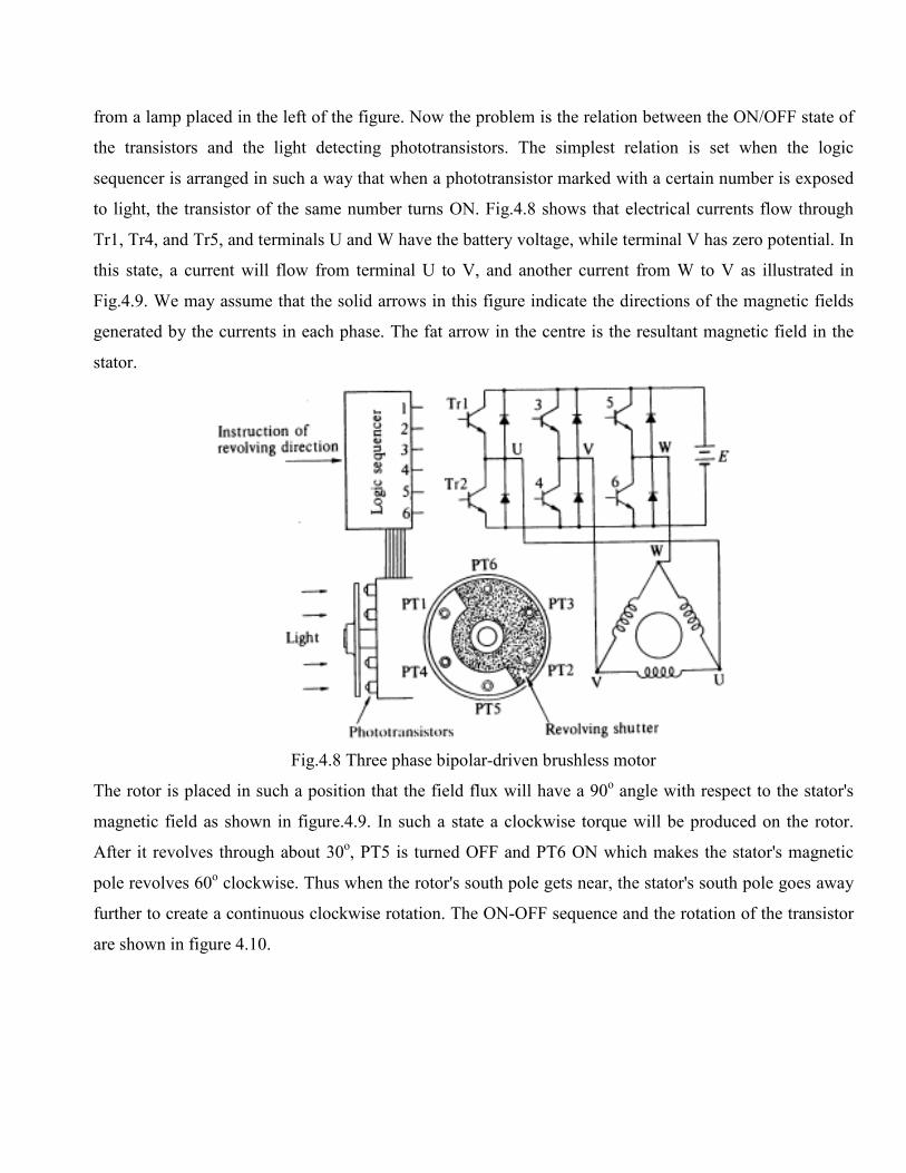
from a lamp placed in the left of the figure. Now the problem is the relation between the ON/OFF state of
the transistors and the light detecting phototransistors. The simplest relation is set when the logic
sequencer is arranged in such a way that when a phototransistor marked with a certain number is exposed
to light, the transistor of the same number turns ON. Fig.4.8 shows that electrical currents flow through
Tr1, Tr4, and Tr5, and terminals U and W have the battery voltage, while terminal V has zero potential. In
this state, a current will flow from terminal U to V, and another current from W to V as illustrated in
Fig.4.9. We may assume that the solid arrows in this figure indicate the directions of the magnetic fields
generated by the currents in each phase. The fat arrow in the centre is the resultant magnetic field in the
stator.
Fig.4.8 Three phase bipolar-driven brushless motor
The rotor is placed in such a position that the field flux will have a 90o angle with respect to the stator's
magnetic field as shown in figure.4.9. In such a state a clockwise torque will be produced on the rotor.
After it revolves through about 30o, PT5 is turned OFF and PT6 ON which makes the stator's magnetic
pole revolves 60o clockwise. Thus when the rotor's south pole gets near, the stator's south pole goes away
further to create a continuous clockwise rotation. The ON-OFF sequence and the rotation of the transistor
are shown in figure 4.10.
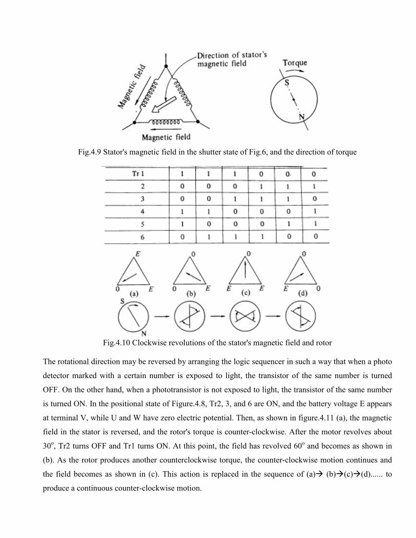
Fig.4.9 Stator's magnetic field in the shutter state of Fig.6, and the direction of torque
Fig.4.10 Clockwise revolutions of the stator's magnetic field and rotor
The rotational direction may be reversed by arranging the logic sequencer in such a way that when a photo
detector marked with a certain number is exposed to light, the transistor of the same number is turned
OFF. On the other hand, when a phototransistor is not exposed to light, the transistor of the same number
is turned ON. In the positional state of Figure.4.8, Tr2, 3, and 6 are ON, and the battery voltage E appears
at terminal V, while U and W have zero electric potential. Then, as shown in figure.4.11 (a), the magnetic
field in the stator is reversed, and the rotor's torque is counter-clockwise. After the motor revolves about
30o, Tr2 turns OFF and Tr1 turns ON. At this point, the field has revolved 60
o and becomes as shown in
(b). As the rotor produces another counterclockwise torque, the counter-clockwise motion continues and
the field becomes as shown in (c). This action is replaced in the sequence of (a)� (b)�(c)�(d)...... to
produce a continuous counter-clockwise motion.
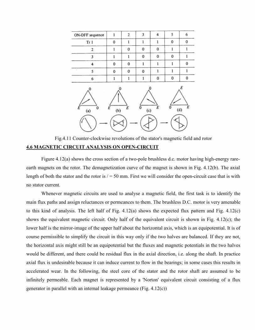
Fig.4.11 Counter-clockwise revolutions of the stator's magnetic field and rotor
4.6 MAGNETIC CIRCUIT ANALYSIS ON OPEN-CIRCUIT
Figure 4.12(a) shows the cross section of a two-pole brushless d.c. motor having high-energy rare-
earth magnets on the rotor. The demagnetization curve of the magnet is shown in Fig. 4.12(b). The axial
length of both the stator and the rotor is / = 50 mm. First we will consider the open-circuit case that is with
no stator current.
Whenever magnetic circuits are used to analyse a magnetic field, the first task is to identify the
main flux paths and assign reluctances or permeances to them. The brushless D.C. motor is very amenable
to this kind of analysis. The left half of Fig. 4.12(a) shows the expected flux pattern and Fig. 4.12(c)
shows the equivalent magnetic circuit. Only half of the equivalent circuit is shown in Fig. 4.12(c); the
lower half is the mirror-image of the upper half about the horizontal axis, which is an equipotential. It is of
course permissible to simplify the circuit in this way only if the two halves are balanced. If they are not,
the horizontal axis might still be an equipotential but the fluxes and magnetic potentials in the two halves
would be different, and there could be residual flux in the axial direction, i.e. along the shaft. In practice
axial flux is undesirable because it can induce current to flow in the bearings; in some cases this results in
accelerated wear. In the following, the steel core of the stator and the rotor shaft are assumed to be
infinitely permeable. Each magnet is represented by a 'Norton' equivalent circuit consisting of a flux
generator in parallel with an internal leakage permeance (Fig. 4.12(c))
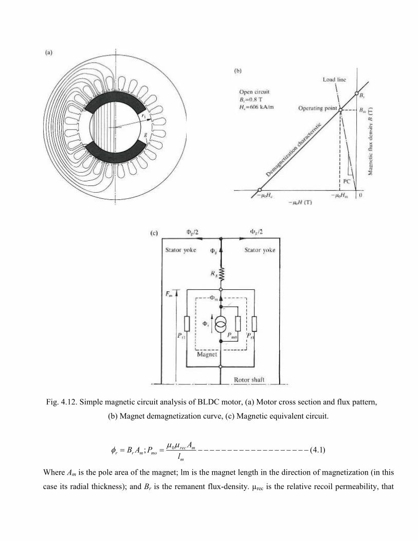
Fig. 4.12. Simple magnetic circuit analysis of BLDC motor, (a) Motor cross section and flux pattern,
(b) Magnet demagnetization curve, (c) Magnetic equivalent circuit.
)1.4(; 0 −−−−−−−−−−−−−−−−−−−==m
mrecmomrr
l
APAB
µµφ
Where Am is the pole area of the magnet; lm is the magnet length in the direction of magnetization (in this
case its radial thickness); and Br is the remanent flux-density. µrec is the relative recoil permeability, that
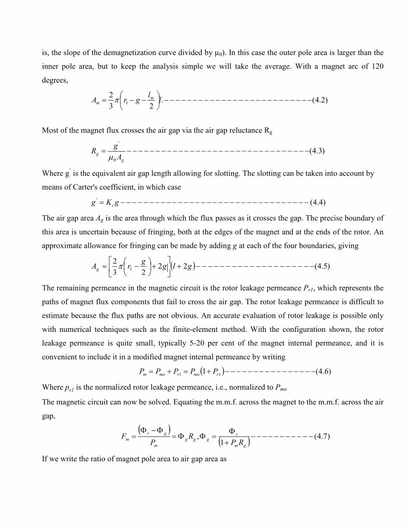
is, the slope of the demagnetization curve divided by µ0). In this case the outer pole area is larger than the
inner pole area, but to keep the analysis simple we will take the average. With a magnet arc of 120
degrees,
)2.4(.23
21 −−−−−−−−−−−−−−−−−−−−−−−−−−
−−= ll
grA mm π
Most of the magnet flux crosses the air gap via the air gap reluctance Rg
)3.4(0
'
−−−−−−−−−−−−−−−−−−−−−−−−−−−−−−−−=g
gA
gR
µ
Where g’ is the equivalent air gap length allowing for slotting. The slotting can be taken into account by
means of Carter's coefficient, in which case
)4.4(' −−−−−−−−−−−−−−−−−−−−−−−−−−−−−−−−−= gKg c
The air gap area Ag is the area through which the flux passes as it crosses the gap. The precise boundary of
this area is uncertain because of fringing, both at the edges of the magnet and at the ends of the rotor. An
approximate allowance for fringing can be made by adding g at each of the four boundaries, giving
( ) )5.4(2223
21 −−−−−−−−−−−−−−−−−−−−+
+
−= glgg
rAg π
The remaining permeance in the magnetic circuit is the rotor leakage permeance Pr1, which represents the
paths of magnet flux components that fail to cross the air gap. The rotor leakage permeance is difficult to
estimate because the flux paths are not obvious. An accurate evaluation of rotor leakage is possible only
with numerical techniques such as the finite-element method. With the configuration shown, the rotor
leakage permeance is quite small, typically 5-20 per cent of the magnet internal permeance, and it is
convenient to include it in a modified magnet internal permeance by writing
( ) )6.4(1 11 −−−−−−−−−−−−−−−−+=+= rmormom PPPPP
Where pr1 is the normalized rotor leakage permeance, i.e., normalized to Pmo
The magnetic circuit can now be solved. Equating the m.m.f. across the magnet to the m.m.f. across the air
gap,
( )
( ) )7.4(1
, −−−−−−−−−−−+Φ
=ΦΦ=Φ−Φ
=gm
rggg
m
gr
mRP
RP
F
If we write the ratio of magnet pole area to air gap area as
)8.4(−−−−−−−−−−−−−−−−−−−−−−−−−−−−−−=Φg
m
A
AC
Then the air gap flux-density can be extracted as
( ) )9.4(1
−−−−−−−−−−−−−−−−−−−−−−−−−+
= Φr
gm
g BPP
CB
The magnet flux-density Bm can be derived by a similar process
( ) )10.4(1
1 1 −−−−−−−−−−−−−−−−−−−−−−−−−+
+= r
gm
gr
m BPP
RPB
Now that we know the magnetic flux-density, it is easy to solve for the magnetizing force Hm in the
magnet using the demagnetization characteristic, Fig. 4.12(b). Mathematically the result is
)11.4(/ −−−−−−−−−−−−−−−−−−−−−−−−
=− mABB
Hreco
mrm µµ
The negative sign signifies a demagnetizing force and indicates that the magnet operates in the second
quadrant of the B-H curve, as expected.
The line drawn from the origin through the operating point in Fig. 4.12(b) is called the 'load-line' and the
absolute value of its slope, normalized to µ0, is called the 'permeance coefficient', PC. The following
formula can be derived for PC
)12.4(1 1 −−−−−−−−−−−−−−−−−−−−−−−−+
=gmo
gr
recRP
RPPC µ
Alternatively, in terms of geometric dimensions
)13.4(
1
'
'
1
−−−−−−−−−−−−−−−−−−−−−−−+
=
Φ
Φ
m
m
recr
l
gC
l
gCP
PC
µ
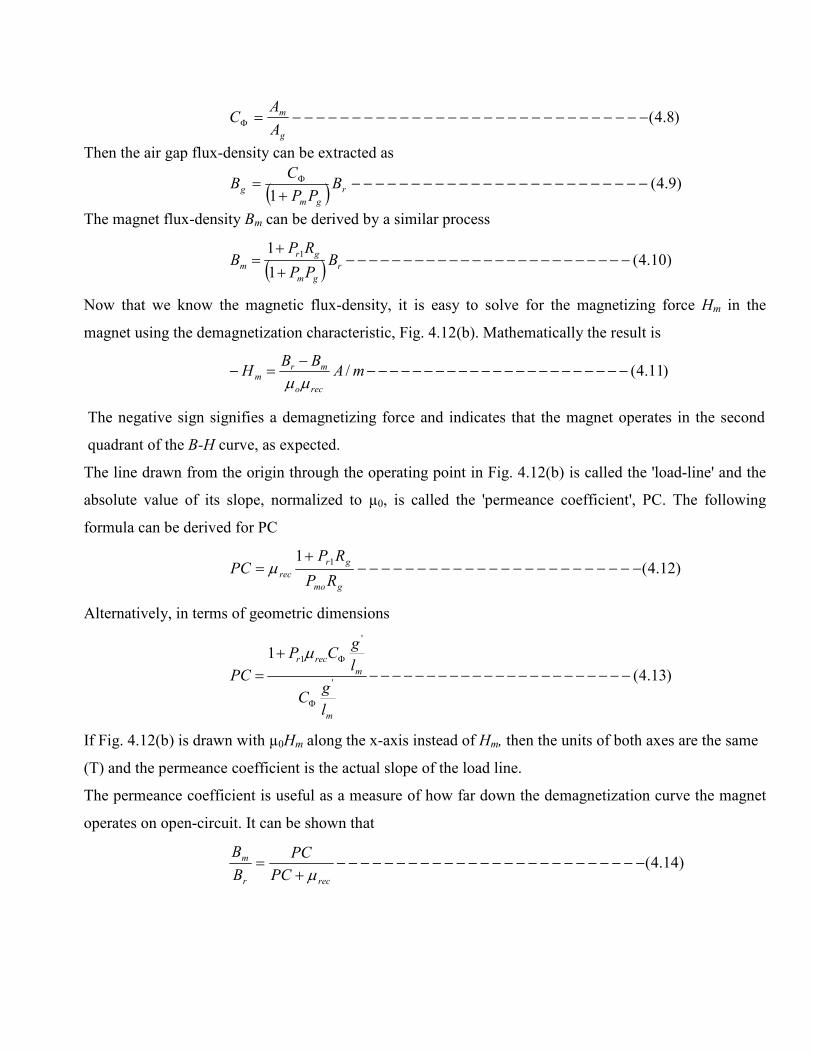
If Fig. 4.12(b) is drawn with µ0Hm along the x-axis instead of Hm, then the units of both axes are the same
(T) and the permeance coefficient is the actual slope of the load line.
The permeance coefficient is useful as a measure of how far down the demagnetization curve the magnet
operates on open-circuit. It can be shown that
)14.4(−−−−−−−−−−−−−−−−−−−−−−−−−−+
=recr
m
PC
PC
B
B
µ
In motors with a weak flux-concentration factor, the magnet should operate on open-circuit at a
high permeance coefficient to maximize the air gap flux-density and the torque per ampere, and to provide
adequate margin against demagnetization by armature reaction. Surface-magnet motors generally do have
a weak flux concentration factor and a permeance coefficient of six or more is quite normal when using
'hard' magnets.
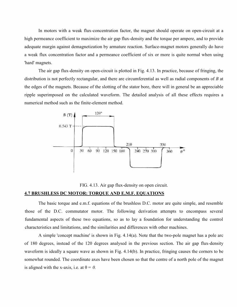
The air gap flux-density on open-circuit is plotted in Fig. 4.13. In practice, because of fringing, the
distribution is not perfectly rectangular, and there are circumferential as well as radial components of B at
the edges of the magnets. Because of the slotting of the stator bore, there will in general be an appreciable
ripple superimposed on the calculated waveform. The detailed analysis of all these effects requires a
numerical method such as the finite-element method.
FIG. 4.13. Air gap flux-density on open circuit.
4.7 BRUSHLESS DC MOTOR: TORQUE AND E.M.F. EQUATIONS
The basic torque and e.m.f. equations of the brushless D.C. motor are quite simple, and resemble
those of the D.C. commutator motor. The following derivation attempts to encompass several
fundamental aspects of these two equations, so as to lay a foundation for understanding the control
characteristics and limitations, and the similarities and differences with other machines.
A simple 'concept machine' is shown in Fig. 4.14(a). Note that the two-pole magnet has a pole arc
of 180 degrees, instead of the 120 degrees analysed in the previous section. The air gap flux-density
waveform is ideally a square wave as shown in Fig. 4.14(b). In practice, fringing causes the corners to be
somewhat rounded. The coordinate axes have been chosen so that the centre of a north pole of the magnet
is aligned with the x-axis, i.e. at θ = 0.
The stator has 12 slots and a three-phase winding. Thus there are two slots per pole per phase.
Each phase winding consists of two adjacent full-pitch coils of N1 turns each, whose axes are displaced
from one another by 30 degrees. The winding is a single-layer winding, and any slot contains N1
conductors from only one phase winding. This winding is equivalent, in the active length, to a degenerate
concentric winding with only one coil per pole per phase, having a fractional pitch of 5/6. This is a more
practical winding than the one analysed because it has less bulky end windings and is generally easier to
assemble. For the same reason, its copper losses are lower.
Consider the flux-linkage 1ψ of coil a1A1 as the rotor rotates. This is shown in Fig. 4.14(c). Note
that θ now represent the movement of the rotor from the reference position in Fig. 4.14(a). The flux-
linkage varies linearly with rotor position because the air gap flux-density set up by the magnet is constant
over each pole-pitch of the rotor. Maximum positive flux-linkage occurs at 0 and maximum negative flux-
linkage at 180°. By integrating the flux-density around the air gap, the maximum flux-linkage of the coil
can be found as
( ) )15.4( 1111max1 −−−−−−−−−−−== ∫ rBNldrBN gπθθψ
and the variation with θ as the rotor rotates from 0 to 180° is given by
( ) )16.4(2
1 max11 −−−−−−−−−−−−−−−−
−= µπθ
θψ
The e.m.f. induced in coil a1A1 is given by
)17.4(1111 −−−−−−−−−−
Ψ−=
Ψ−=
Ψ−=
θω
θθ d
d
dt
d
d
d
dt
de
This gives )18.4(][2 111 −−−−−−−−−−−−−−−−−= VoltslrBNe g ω
Fig. 4.14(d). Note that the waveform of e.m.f. in this full-pitch coil with respect to time is an exact
replica of the flux-density waveform with respect to position around the rotor in Fig. 4.14(b).
The e.m.f. induced in the second coil of phase A is identical, but retarded in phase by 30°. This is
shown in Fig. 4.14(e). If the two coils are connected in series, the total phase voltage is the sum of the two
separate coil voltages, and this is shown in Fig. 4.14(f). The basic effect of distributing the winding into
two coils is to produce a stepped e.m.f. waveform. In practice, fringing causes its corners to be rounded, as
shown by the dotted lines. The waveform then has the 'trapezoidal' shape that is characteristic of the
brushless D.C. motor. With 180° magnet arcs and two slots per pole per phase, the flat top of this
waveform is ideally 150° wide, but in practice the fringing field reduces this to a somewhat smaller value,
possibly as little as 120°.
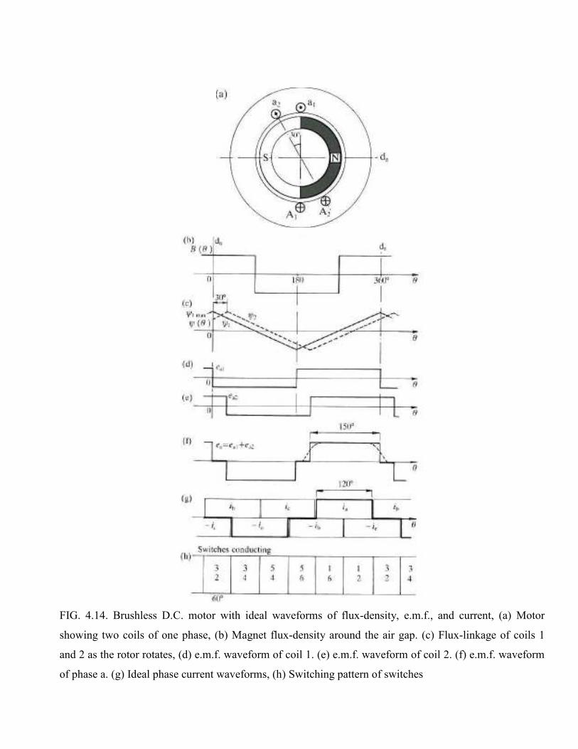
FIG. 4.14. Brushless D.C. motor with ideal waveforms of flux-density, e.m.f., and current, (a) Motor
showing two coils of one phase, (b) Magnet flux-density around the air gap. (c) Flux-linkage of coils 1
and 2 as the rotor rotates, (d) e.m.f. waveform of coil 1. (e) e.m.f. waveform of coil 2. (f) e.m.f. waveform
of phase a. (g) Ideal phase current waveforms, (h) Switching pattern of switches
The magnitude of the flat-topped phase e.m.f. is given by
)19.4(][2 11 −−−−−−−−−−−−−−−−−= VoltslrBNe gph ω
Where Nph is the number of turns in series per phase. In this case
)20.4(2 1 −−−−−−−−−−−−−−−−−−−−−−−= NN ph
because the two coils considered are assumed to be in series. In a machine with p pole-pairs, the equation
remains valid provided Nph is the number of turns in series per phase and ω is in mechanical radians per
second.
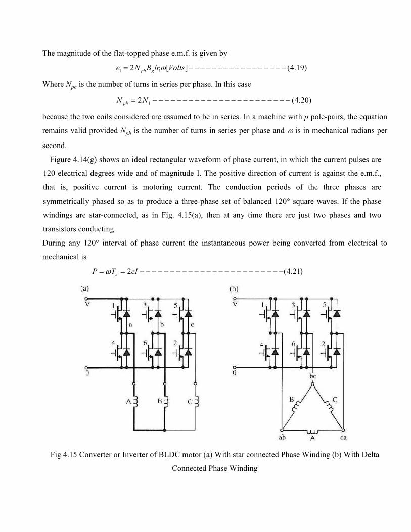
Figure 4.14(g) shows an ideal rectangular waveform of phase current, in which the current pulses are
120 electrical degrees wide and of magnitude I. The positive direction of current is against the e.m.f.,
that is, positive current is motoring current. The conduction periods of the three phases are
symmetrically phased so as to produce a three-phase set of balanced 120° square waves. If the phase
windings are star-connected, as in Fig. 4.15(a), then at any time there are just two phases and two
transistors conducting.
During any 120° interval of phase current the instantaneous power being converted from electrical to
mechanical is
)21.4(2 −−−−−−−−−−−−−−−−−−−−−−−−== eITP eω
Fig 4.15 Converter or Inverter of BLDC motor (a) With star connected Phase Winding (b) With Delta
Connected Phase Winding
The '2' in this equation arises from the fact that two phases are conducting. Using the expression derived
above for the e.m.f., the electromagnetic torque is given by
)22.4(][4 1 −−−−−−−−−−−−−−−−−= NmIlrBNT gphe
This equation is valid for any number of pole-pairs. The similarity between the brushless motor
and the commutator motor can now be seen. Writing E=2e to represent the combined e.m.f. of two phases
in series, the e.m.f. and torques equations can be written in the form
)23.4(IKT and −−−−−−−−−−−−−−−−−Φ=Φ= ωKE
Where lrNK ph π1gB and 4 =Φ=
k is the 'armature constant' and Φ is the flux. These equations for e.m.f. and torque are exactly the same
as for the D.C. commutator motor; only the form of the constant k is different. It is clear that with ideal
wave shapes and with perfect commutation, these equations are true at all instants of time. The electronic
commutation of the converter switches has thus assumed the function of the mechanical commutator in the
commutator motor, to give a pure 'd.c.' machine with constant, ripple-free torque.
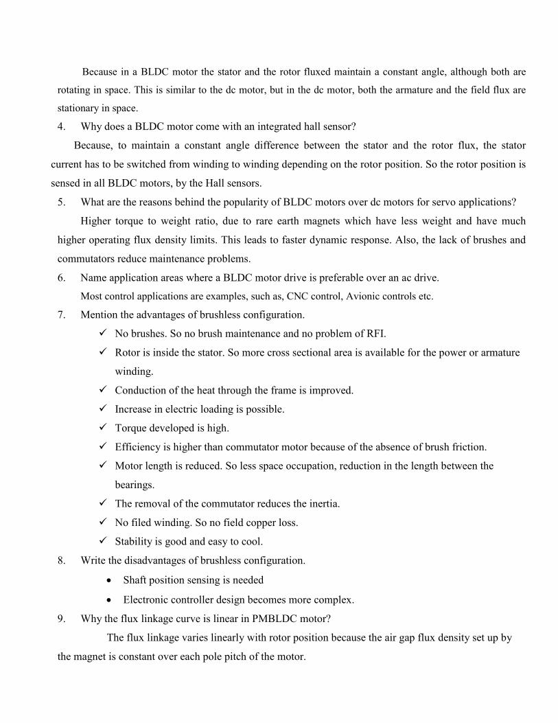
4.8 TORQUE/SPEED CHACTERISTICS OF BLDC MOTOR
The torque/speed curve of the ideal brushless motor can be derived from the foregoing equations.
If the commutation is perfect and the current waveforms are exactly as shown in Fig. 4.14(g), and if the
converter is supplied from an ideal direct voltage source V, then at any instant the following equation can
be written for the D.C. terminal voltage:
)24.4(−−−−−−−−−−−−−−−−−−−−−+= RIEV
Where R is the sum of two phase resistances in series and E is the sum of two phase e.m.f.s in series. This
equation is exactly the same as that of the commutator motor. The voltage drops across two converter
switches in series are omitted, but they correspond exactly to the two brush voltage drops in series in the
commutator motor.
Using this equation together with the e.m.f. and torque equations, the torque/speed characteristic can be
derived as:
)25.4(10
0 −−−−−−−−−−−−−−−−−−−−−
−=T
Tωω
Where the no-load speed is
)26.4(sec/0 −−−−−−−−−−−−−−−−−−−−−Φ
= radk
Vω
and the stall torque is given by
)27.4(00 −−−−−−−−−−−−−−−−−−−−−Φ= IkT
This is the torque with the motor stalled, i.e. at zero speed. The stall current is given by
)28.4(0 −−−−−−−−−−−−−−−−−−−−−−=R
VI
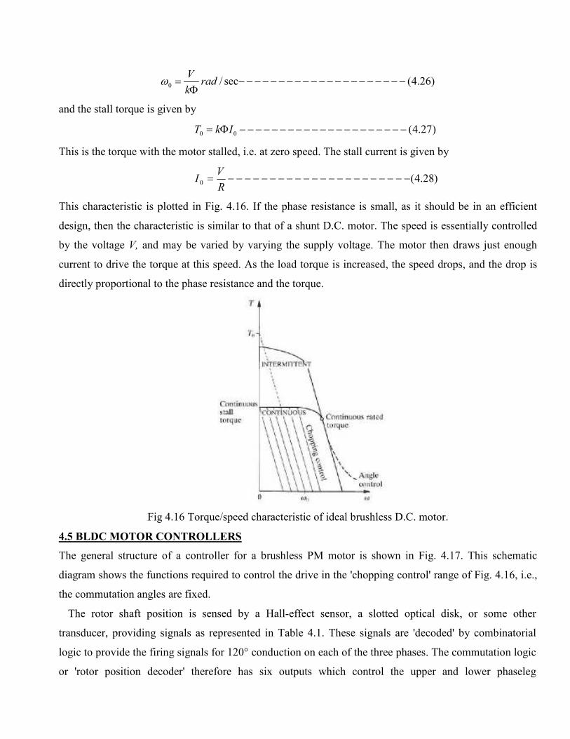
This characteristic is plotted in Fig. 4.16. If the phase resistance is small, as it should be in an efficient
design, then the characteristic is similar to that of a shunt D.C. motor. The speed is essentially controlled
by the voltage V, and may be varied by varying the supply voltage. The motor then draws just enough
current to drive the torque at this speed. As the load torque is increased, the speed drops, and the drop is
directly proportional to the phase resistance and the torque.
Fig 4.16 Torque/speed characteristic of ideal brushless D.C. motor.
4.5 BLDC MOTOR CONTROLLERS
The general structure of a controller for a brushless PM motor is shown in Fig. 4.17. This schematic
diagram shows the functions required to control the drive in the 'chopping control' range of Fig. 4.16, i.e.,
the commutation angles are fixed.
The rotor shaft position is sensed by a Hall-effect sensor, a slotted optical disk, or some other
transducer, providing signals as represented in Table 4.1. These signals are 'decoded' by combinatorial
logic to provide the firing signals for 120° conduction on each of the three phases. The commutation logic
or 'rotor position decoder' therefore has six outputs which control the upper and lower phaseleg
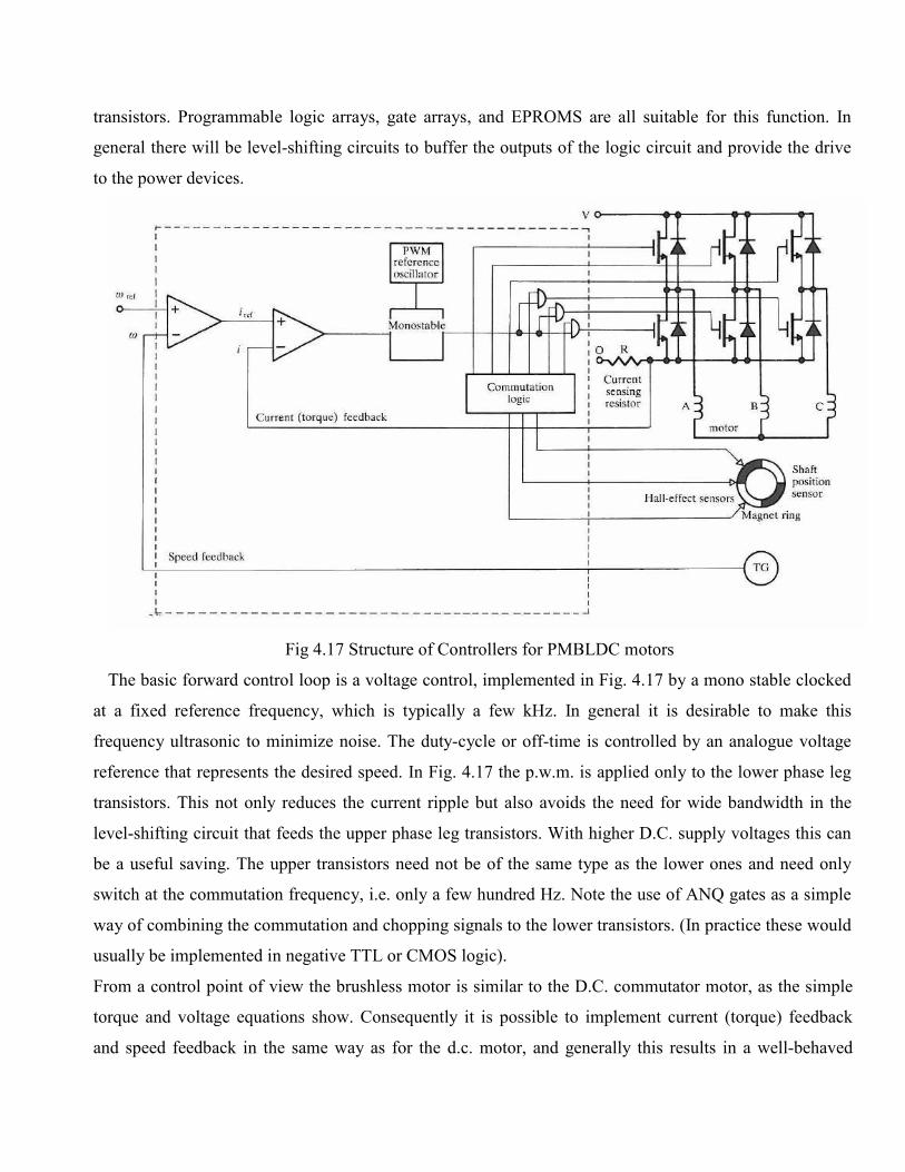
transistors. Programmable logic arrays, gate arrays, and EPROMS are all suitable for this function. In
general there will be level-shifting circuits to buffer the outputs of the logic circuit and provide the drive
to the power devices.
Fig 4.17 Structure of Controllers for PMBLDC motors
The basic forward control loop is a voltage control, implemented in Fig. 4.17 by a mono stable clocked
at a fixed reference frequency, which is typically a few kHz. In general it is desirable to make this
frequency ultrasonic to minimize noise. The duty-cycle or off-time is controlled by an analogue voltage
reference that represents the desired speed. In Fig. 4.17 the p.w.m. is applied only to the lower phase leg
transistors. This not only reduces the current ripple but also avoids the need for wide bandwidth in the
level-shifting circuit that feeds the upper phase leg transistors. With higher D.C. supply voltages this can
be a useful saving. The upper transistors need not be of the same type as the lower ones and need only
switch at the commutation frequency, i.e. only a few hundred Hz. Note the use of ANQ gates as a simple
way of combining the commutation and chopping signals to the lower transistors. (In practice these would
usually be implemented in negative TTL or CMOS logic).
From a control point of view the brushless motor is similar to the D.C. commutator motor, as the simple
torque and voltage equations show. Consequently it is possible to implement current (torque) feedback
and speed feedback in the same way as for the d.c. motor, and generally this results in a well-behaved
system although compensation may be necessary in either or both loops to improve stability and transient
response. A tight speed control is thus possible over a wide range of speed and torque using relatively
simple techniques that are familiar with commutator motors. This is in contrast, to some degree, with the
a.c. induction motor, which cannot accommodate speed and torque control loops in this form without
having reference-frame transformations, as in the field-oriented control technique, or their equivalent.
Sometimes the instantaneous current in the brushless PM motor is regulated in each phase by a
hysteresis-type regulator which maintains the current within adjustable limits. This is called 'current-mode'
control and several algorithms are possible to control the switching. In this case current sensors are needed
in each phase, and their bandwidth must obviously be considerably wider than that of the sensing resistor
shown in Fig. 4.17. The speed feedback signal, derived in Fig. 4.17 from a tachometer-generator TG, can
also be derived from the shaft position sensor by a frequency-to-voltage converter. This technique only
works at high speeds.
Many of the functions of the circuit in Fig. 4.17 can be performed digitally, and it is increasingly
common to have a serial communications interface that permits the system to be computer controlled. In
high-performance systems the shaft position sensor may be a resolver or optical encoder, with special-
purpose decoding circuitry. At this level of control sophistication, it is possible to fine-tune the firing
angles and the p.w.m. control as a function of speed and load, to improve various aspects of performance
such as efficiency, dynamic performance, or speed range.
There is a wide range of integrated circuits available with many of the functions in Fig. 4.17. The
functions inside the dotted line are all found on many such products, as well as many protective functions
such as over- and under-voltage protection, over current protection, and lockout protection (preventing the
upper and lower switches in one phase leg from turning on at the same time and causing a 'shoot-through'
failure).
4.6 SINE WAVE PM BRUSHLESS MOTOR DRIVES (PMSM)
4.6.1 CONSTRUCTION
Synchronous motors operate at constant speed in absolute synchronism with the line frequency.
Synchronous motors are classified according to their rotor design, construction, materials and operation
into the four basic groups.
� Electromagnetically excited motor
� PM motors
� Reluctance motors
� Hysterics motor
In electromagnetically excited and PM motors a cage winding is frequently mounted on salient
pole rotors to provide asynchronous starting and to damp oscillations under transient conditions, so called
damper. Recent development in rare earth PM materials and power electronics have opened new prospects
on the design, construction and application of PM synchronous motors.
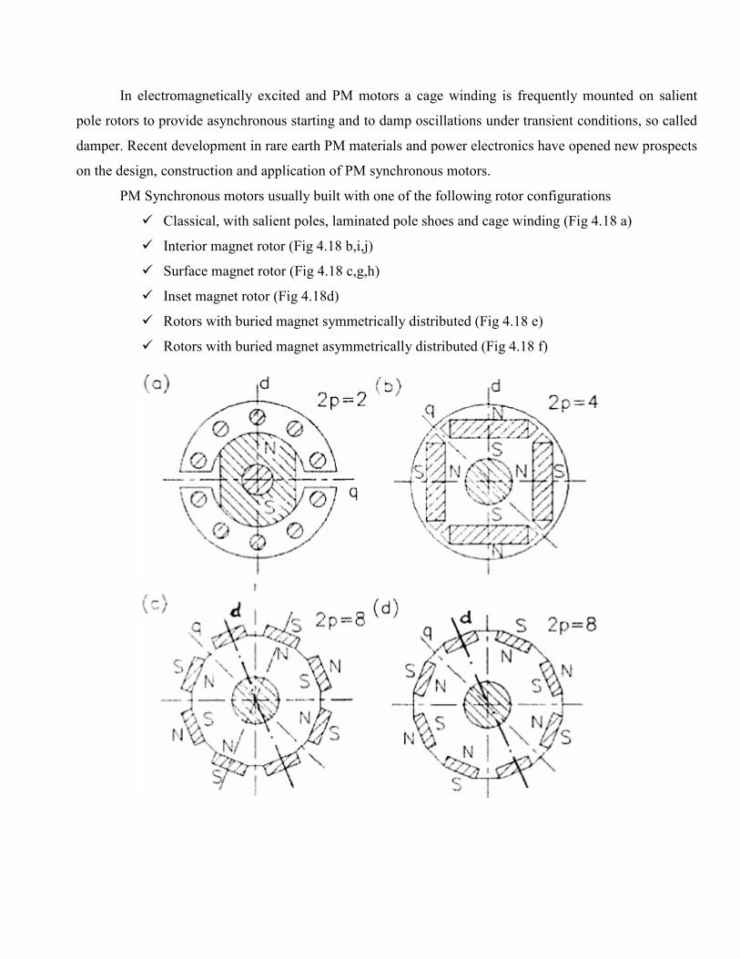
PM Synchronous motors usually built with one of the following rotor configurations
� Classical, with salient poles, laminated pole shoes and cage winding (Fig 4.18 a)
� Interior magnet rotor (Fig 4.18 b,i,j)
� Surface magnet rotor (Fig 4.18 c,g,h)
� Inset magnet rotor (Fig 4.18d)
� Rotors with buried magnet symmetrically distributed (Fig 4.18 e)
� Rotors with buried magnet asymmetrically distributed (Fig 4.18 f)
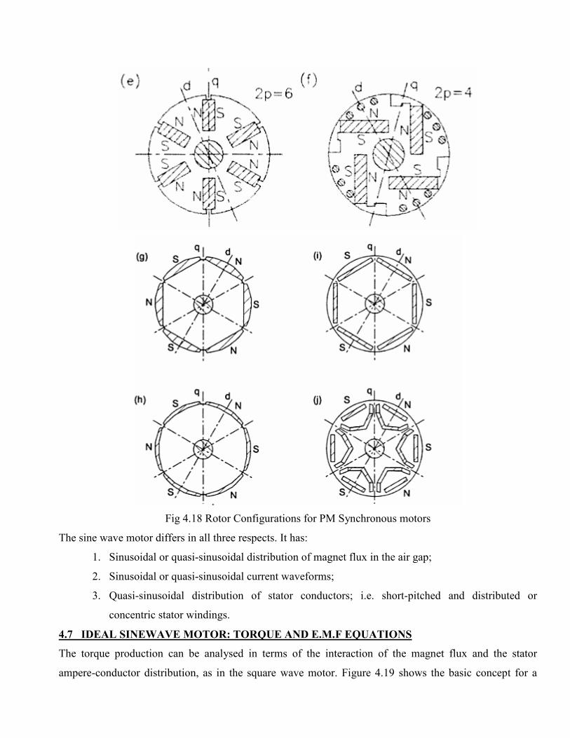
Fig 4.18 Rotor Configurations for PM Synchronous motors
The sine wave motor differs in all three respects. It has:
1. Sinusoidal or quasi-sinusoidal distribution of magnet flux in the air gap;
2. Sinusoidal or quasi-sinusoidal current waveforms;
3. Quasi-sinusoidal distribution of stator conductors; i.e. short-pitched and distributed or
concentric stator windings.
4.7 IDEAL SINEWAVE MOTOR: TORQUE AND E.M.F EQUATIONS
The torque production can be analysed in terms of the interaction of the magnet flux and the stator
ampere-conductor distribution, as in the square wave motor. Figure 4.19 shows the basic concept for a
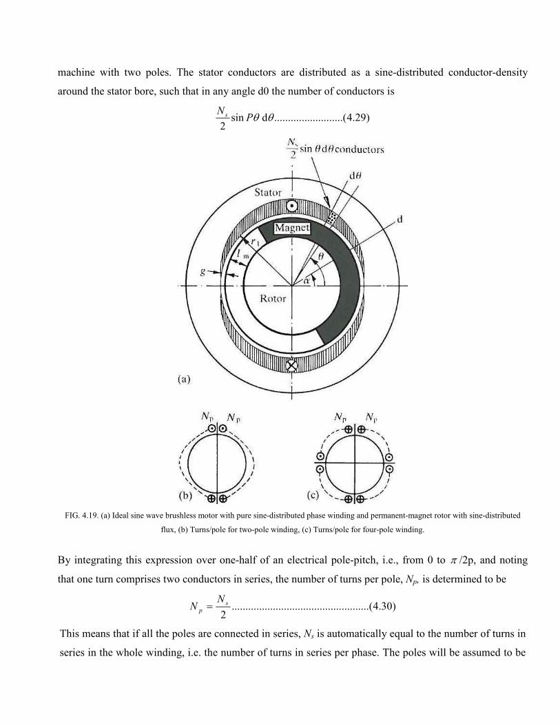
machine with two poles. The stator conductors are distributed as a sine-distributed conductor-density
around the stator bore, such that in any angle d0 the number of conductors is
)29.4.....(....................d sin2
θθPN s
FIG. 4.19. (a) Ideal sine wave brushless motor with pure sine-distributed phase winding and permanent-magnet rotor with sine-distributed
flux, (b) Turns/pole for two-pole winding, (c) Turns/pole for four-pole winding.
By integrating this expression over one-half of an electrical pole-pitch, i.e., from 0 to π /2p, and noting
that one turn comprises two conductors in series, the number of turns per pole, Np, is determined to be
)30.4(..................................................2
sp
NN =
This means that if all the poles are connected in series, Ns is automatically equal to the number of turns in
series in the whole winding, i.e. the number of turns in series per phase. The poles will be assumed to be
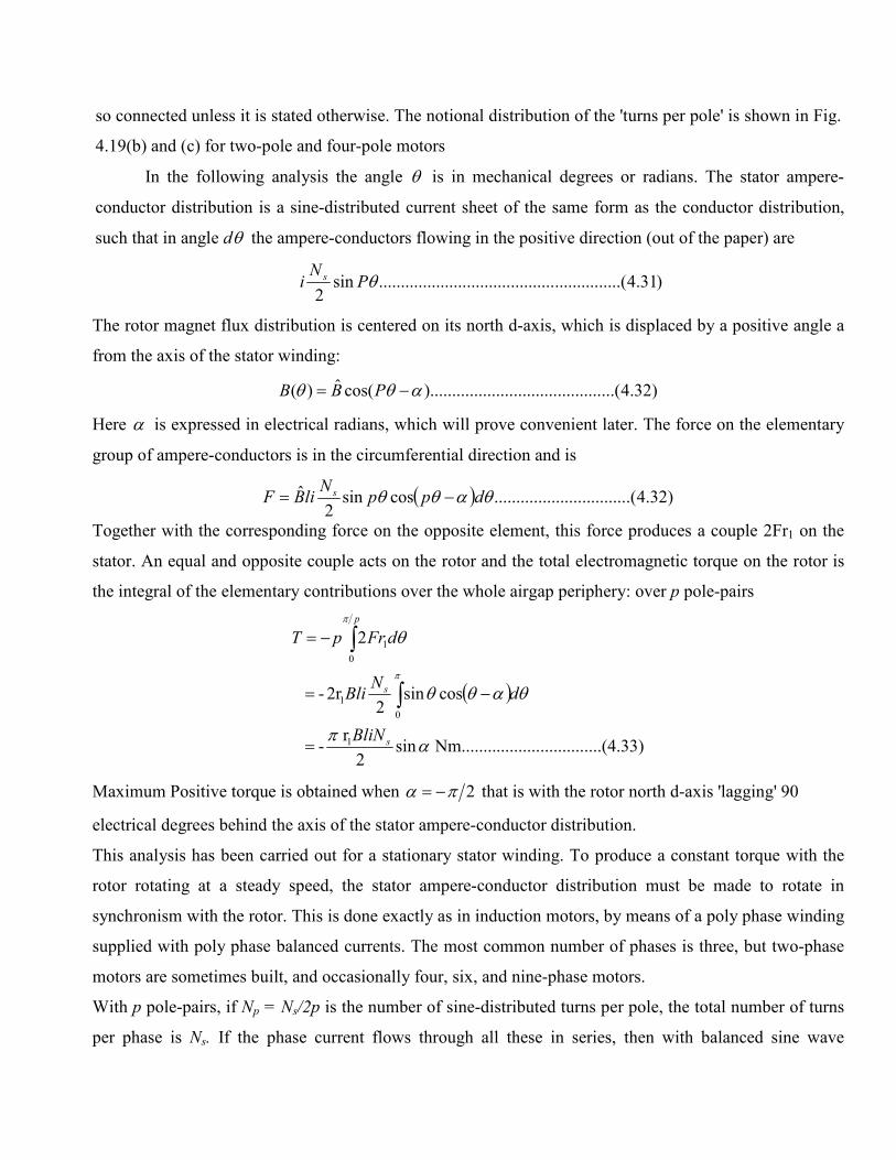
so connected unless it is stated otherwise. The notional distribution of the 'turns per pole' is shown in Fig.
4.19(b) and (c) for two-pole and four-pole motors
In the following analysis the angle θ is in mechanical degrees or radians. The stator ampere-
conductor distribution is a sine-distributed current sheet of the same form as the conductor distribution,
such that in angle dθ the ampere-conductors flowing in the positive direction (out of the paper) are
)31.4.....(..................................................sin2
θPNi s
The rotor magnet flux distribution is centered on its north d-axis, which is displaced by a positive angle a
from the axis of the stator winding:
)32.4...(..............................).........cos(ˆ)( αθθ −= PBB
Here α is expressed in electrical radians, which will prove convenient later. The force on the elementary
group of ampere-conductors is in the circumferential direction and is
( ) )32.4.(..............................cossin2
ˆ θαθθ dppN
liBF s −=
Together with the corresponding force on the opposite element, this force produces a couple 2Fr1 on the
stator. An equal and opposite couple acts on the rotor and the total electromagnetic torque on the rotor is
the integral of the elementary contributions over the whole airgap periphery: over p pole-pairs
( )
....(4.33)....................Nm........ sin2
r -
cossin2
2r-
2
1
0
1
0
1
απ
θαθθ
θ
π
π
s
s
p
BliN
dN
Bli
dFrpT
=
−=
−=
∫
∫
Maximum Positive torque is obtained when 2πα −= that is with the rotor north d-axis 'lagging' 90
electrical degrees behind the axis of the stator ampere-conductor distribution.
This analysis has been carried out for a stationary stator winding. To produce a constant torque with the
rotor rotating at a steady speed, the stator ampere-conductor distribution must be made to rotate in
synchronism with the rotor. This is done exactly as in induction motors, by means of a poly phase winding
supplied with poly phase balanced currents. The most common number of phases is three, but two-phase
motors are sometimes built, and occasionally four, six, and nine-phase motors.
With p pole-pairs, if Np = Ns/2p is the number of sine-distributed turns per pole, the total number of turns
per phase is Ns. If the phase current flows through all these in series, then with balanced sine wave
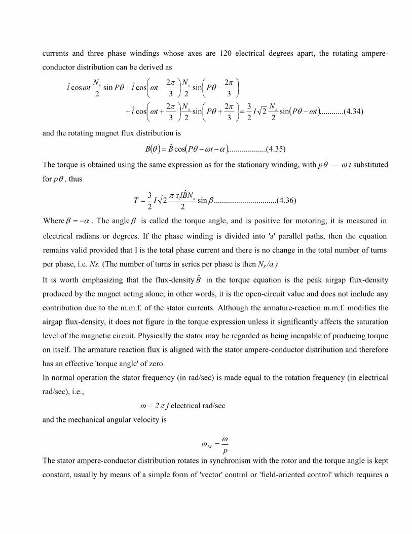
currents and three phase windings whose axes are 120 electrical degrees apart, the rotating ampere-
conductor distribution can be derived as
( ) )34.4..(..........sin2
22
3
3
2sin
23
2cosˆ
3
2sin
23
2cosˆsin
2cosˆ
tPN
IPN
ti
PN
tiPNti
ss
ss
ωθπ
θπ
ω
πθ
πωθω
−=
+
++
−
−+
and the rotating magnet flux distribution is
( ) ( ) )35.4.........(..........cosˆ αωθθ −−= tPBB
The torque is obtained using the same expression as for the stationary winding, with pθ — ω t substituted
for pθ , thus
)36.4.(..............................sin2
ˆr 2
2
3 1 βπ sNBlIT =
Where αβ −= . The angle β is called the torque angle, and is positive for motoring; it is measured in
electrical radians or degrees. If the phase winding is divided into 'a' parallel paths, then the equation
remains valid provided that I is the total phase current and there is no change in the total number of turns
per phase, i.e. Ns. (The number of turns in series per phase is then Ns /a.)
It is worth emphasizing that the flux-density B̂ in the torque equation is the peak airgap flux-density
produced by the magnet acting alone; in other words, it is the open-circuit value and does not include any
contribution due to the m.m.f. of the stator currents. Although the armature-reaction m.m.f. modifies the
airgap flux-density, it does not figure in the torque expression unless it significantly affects the saturation
level of the magnetic circuit. Physically the stator may be regarded as being incapable of producing torque
on itself. The armature reaction flux is aligned with the stator ampere-conductor distribution and therefore
has an effective 'torque angle' of zero.
In normal operation the stator frequency (in rad/sec) is made equal to the rotation frequency (in electrical
rad/sec), i.e.,
ω = 2π f electrical rad/sec
and the mechanical angular velocity is
pM
ωω =
The stator ampere-conductor distribution rotates in synchronism with the rotor and the torque angle is kept
constant, usually by means of a simple form of 'vector' control or 'field-oriented control' which requires a
shaft position sensor (i.e. encoder or resolver feedback). If the supply frequency and the rotation
frequency were unequal, the motor would be running asynchronously. No average torque would be
produced, but there would be a large alternating torque at the 'beat' frequency or pole-slipping frequency.
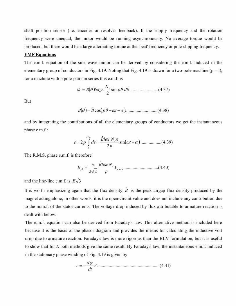
EMF Equations
The e.m.f. equation of the sine wave motor can be derived by considering the e.m.f. induced in the
elementary group of conductors in Fig. 4.19. Noting that Fig. 4.19 is drawn for a two-pole machine (p = l),
for a machine with p pole-pairs in series this e.m.f. is
( ) )37.4.....(.................... sin2
1 θθωθ dpN
rlBde sm=
But
( ) ( ) )38.4........(....................cosˆ αωθθ −−= tpBB
and by integrating the contributions of all the elementary groups of conductors we get the instantaneous
phase e.m.f.:
( ) )39.4.........(..........sin2
ˆ2
0
1 αωπωπ
+== ∫ tp
NrlBdepe
p
s
The R.M.S. phase e.m.f. is therefore
)40.4(..............................ˆ
22..
1smr
sph V
p
NrlBE
ωπ=
and the line-line e.m.f. is 3E
It is worth emphasizing again that the flux-density B̂ is the peak airgap flux-density produced by the
magnet acting alone; in other words, it is the open-circuit value and does not include any contribution due
to the m.m.f. of the stator currents. The voltage drop induced by flux attributable to armature reaction is
dealt with below.
The e.m.f. equation can also be derived from Faraday's law. This alternative method is included here
because it is the basis of the phasor diagram and provides the means for calculating the inductive volt
drop due to armature reaction. Faraday's law is more rigorous than the BLV formulation, but it is useful
to show that for E both methods give the same result. By Faraday's law, the instantaneous e.m.f. induced
in the stationary phase winding of Fig. 4.19 is given by
)41.4....(..................................................Vdt
de
ψ−=
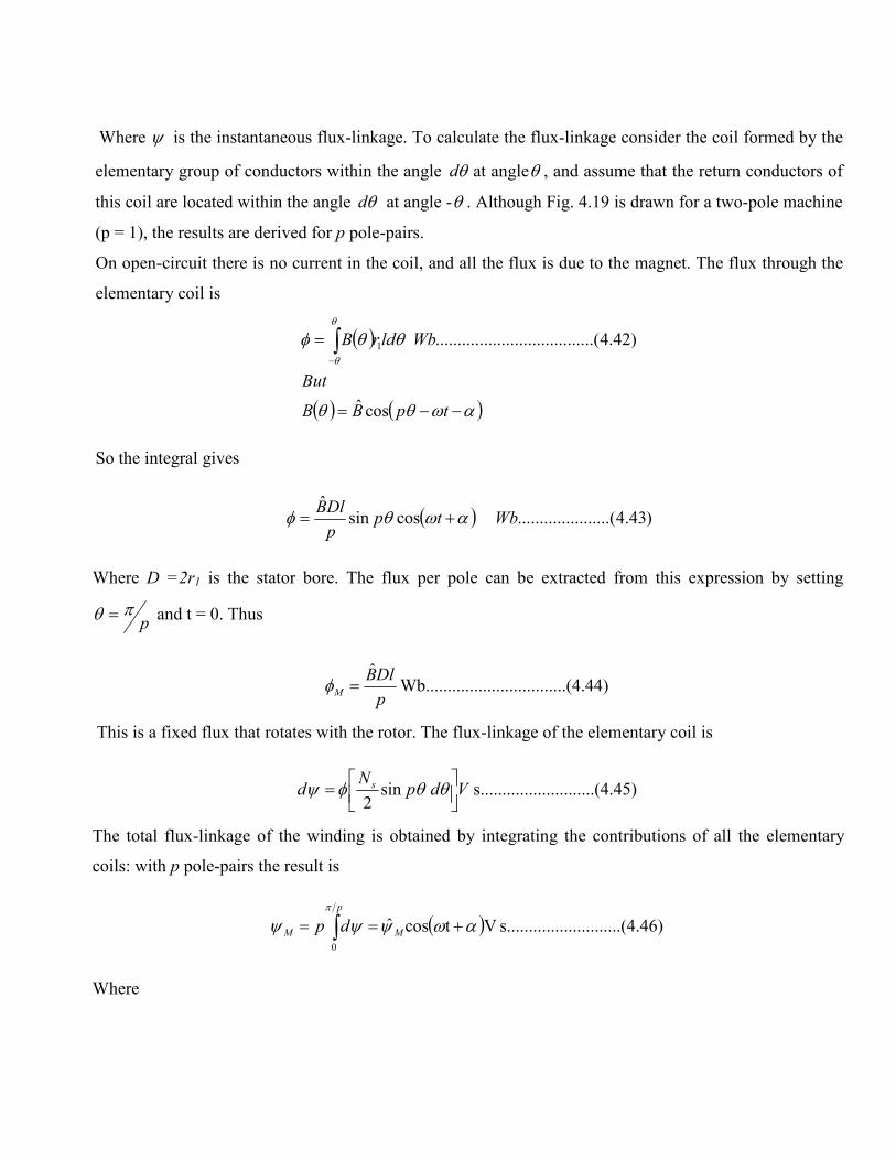
Where ψ is the instantaneous flux-linkage. To calculate the flux-linkage consider the coil formed by the
elementary group of conductors within the angle θd at angleθ , and assume that the return conductors of
this coil are located within the angle θd at angle -θ . Although Fig. 4.19 is drawn for a two-pole machine
(p = 1), the results are derived for p pole-pairs.
On open-circuit there is no current in the coil, and all the flux is due to the magnet. The flux through the
elementary coil is
( )
( ) ( )αωθθ
θθφθ
θ
−−=
= ∫−
tpBB
But
WbldrB
cosˆ
)42.4......(.............................. 1
So the integral gives
( ) )43.4.(.................... cossinˆ
Wbtpp
DlBαωθφ +=
Where D =2r1 is the stator bore. The flux per pole can be extracted from this expression by setting
pπθ = and t = 0. Thus
).....(4.44.................... Wb.......ˆ
p
DlBM =φ
This is a fixed flux that rotates with the rotor. The flux-linkage of the elementary coil is
45).......(4...........s......... sin2
VdpN
d s
= θθφψ
The total flux-linkage of the winding is obtained by integrating the contributions of all the elementary
coils: with p pole-pairs the result is
( ) 46).......(4...........s......... Vtcosˆ
0
αωψψψπ
+== ∫p
MM dp
Where
47).......(4...........s......... VN42
ˆˆ
Ms1 φ
ππψ ==
p
NlrB sM
The subscript 'M' has been added as a reminder that the flux is produced only by the magnet. By Faraday's
law the instantaneous phase e.m.f. is
( ) 48).......(4...........V.........tsinˆe αωψωψ
+=−= MM
dt
d
The R.M.S. phase e.mf. is
9)......(4.4....................VB̂
222
ˆE r.m.s
1Mph
p
Nrl sωπψω==
4.8 Torque-speed characteristics
Ideal motors were considered in the analysis above; in practice, the construction of the stator windings,
and particularly the effect of the stator's slots, has a significant effect on the motor's performance and
characteristics. In addition, the location of the magnets either mounted on the surface or within the body of
the rotor, has to be considered in detail.
The torque equation can also be expressed in the form;
)51.4.......(..........sin3
hence
)50.4(....................sin
m βω
ω
β
IET
and
IpET
p
s
p
=
=
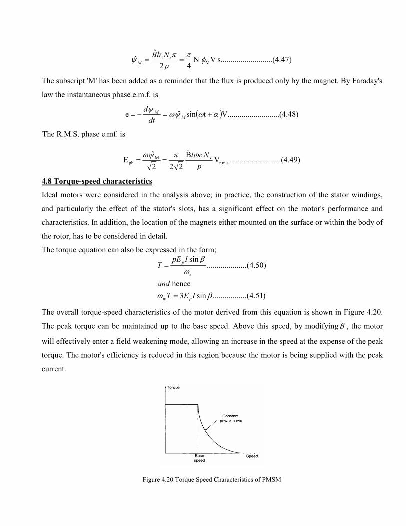
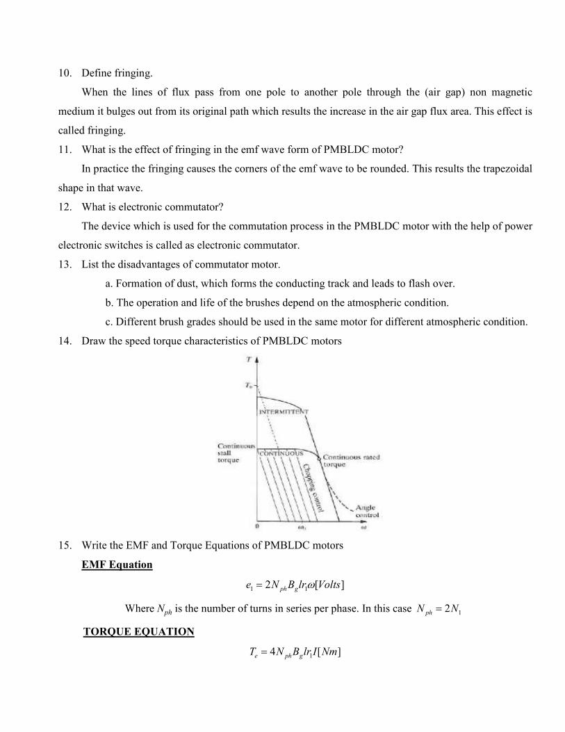
The overall torque-speed characteristics of the motor derived from this equation is shown in Figure 4.20.
The peak torque can be maintained up to the base speed. Above this speed, by modifying β , the motor
will effectively enter a field weakening mode, allowing an increase in the speed at the expense of the peak
torque. The motor's efficiency is reduced in this region because the motor is being supplied with the peak
current.
Figure 4.20 Torque Speed Characteristics of PMSM
4.9 PERMANENT MAGNET DC COMMUTATOR MOTORS
4.9.1 CONSTRUCTION
A D.C. PM Commutator motor can be compared with a D.C. separately excited motor. The only
difference is in the excitation flux gφ in the air gap: for a PM motor gφ = const whilst for a separately
excited motor gφ can be controlled. This means that the speed of a standard D.C. PM commutator motor
can normally only be controlled by changing the armature input voltage or armature current. A typical
D.C. PM Commutator motor is shown in Fig. 4.1(b). By adding an additional field excitation winding, the
flux gφ as well as the speed can be changed in a certain limited range. Alnico PMs used to be common in
motors having ratings in the range of 0.5 to 150 kW. Ceramic magnets are now most popular and
economical in fractional horsepower motors and may have an economic advantage over Alnico up to
about 7.5 kW. Rare-earth magnet materials are costly, but are the best economic choice in small motors.
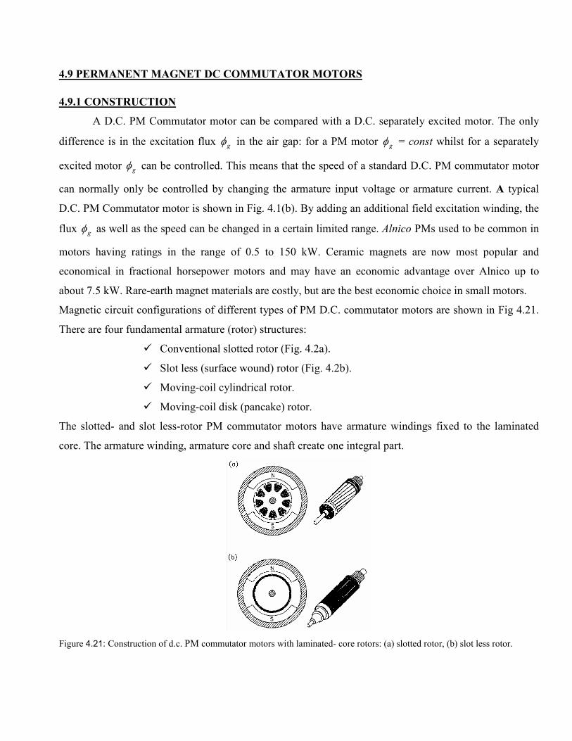
Magnetic circuit configurations of different types of PM D.C. commutator motors are shown in Fig 4.21.
There are four fundamental armature (rotor) structures:
� Conventional slotted rotor (Fig. 4.2a).
� Slot less (surface wound) rotor (Fig. 4.2b).
� Moving-coil cylindrical rotor.
� Moving-coil disk (pancake) rotor.
The slotted- and slot less-rotor PM commutator motors have armature windings fixed to the laminated
core. The armature winding, armature core and shaft create one integral part.
Figure 4.21: Construction of d.c. PM commutator motors with laminated- core rotors: (a) slotted rotor, (b) slot less rotor.
4.9.1.1 Slotted-rotor PM D.C. motors
The core of a slotted rotor is a lamination of silicon steel sheet or carbon steel sheet. The armature
winding is located in the rotor slots. The torque acts on the conductors secured in the slots and reinforced
by the slot insulation and epoxy resin. Thus a slotted rotor is more durable and reliable than a slot less
rotor (Fig. 4.2a). A core having many slots is usually desirable, because the greater the number of slots,
the less the cogging torque and electromagnetic noise. Cores having even numbers of slots are usually
used for the motors manufactured by an automated mass production process because of the ease of
production. From the motor quality point of view, ferromagnetic cores with odd numbers of slots are
preferred due to low cogging torque.
4.9.1.2. Slot less-rotor PM motors
Extremely low cogging torque can be produced by fixing the windings on a cylindrical steel core
without any slots (Fig. 4.2b). In this case the torque is exerted on the conductors uniformly distributed on
the rotor surface. However, the flux decreases in comparison with the slotted rotor since the gap between
the rotor core and the pole shoes is larger. Therefore, larger volume of PMs must be used to get sufficient
magnetic flux.
4.10 TORQUE AND EMF EQUATIONS
4.10.1 TERMINAL VOLTAGE
From the Kirchhoff’s voltage law, the terminal (input) voltage is
)52.4...(....................braa VRIEV ∆++= ∑
Where E is the voltage induced in the armature winding (back EMF), Ia, is the armature current, ∑ aR is
the resistance of the armature circuit and brV∆ , is the brush voltage drop. The brush voltage drop is
approximately constant and for most typical D.C. motors is practically independent of the armature
current.
4.10.2 ARMATURE WINDING EMF
The EMF induced in the armature winding by the main flux gφ in the air gap is
)53.4....(....................gEg ncpna
NE Φ=Φ=
Where N is the number of armature conductors, a is the number of pairs of armature current parallel paths,
p is the number of pole pairs, gφ is the air gap (useful) magnetic flux, and
)54.4.......(..................................................a
Nc
p
E =
is the EMF constant or armature constant. For a. PM excitation tConscK gEE tan=Φ= , thus3
)55.4.......(..................................................nKE E=
The following relationship exists between the number of armature conductors N and the number of
commutator segments C:
)56.4.......(..................................................2 cCNN =
Where NC is the number of turns per armature coil
4.10.3 ELECTROMAGNETIC (DEVELOPED) TORQUE
The electromagnetic torque developed by the D.C. commutator motor is
ππ
φφπ
22
)57.4......(........................................2
ET
agTagd
c
a
Npc
where
IcIp
a
NT
==
==
is the torque constant. The electromagnetic torque is proportional to the armature current. PMs produce a
constant field flux gφ = const (neglecting the armature reaction). The developed torque is
gTT
aTd
ck
where
IkT
φ=
= )58.4......(........................................
TWO MARKS QUESTIONS AND ANSWERS
1. Mention the kinds of permanent magnet used in BLDC motor.
� Alnico magnet
� Ferrite or ceramic magnet
� Rare earth magnet (Samarium cobalt magnet)
2. Mention the types of Permanent Magnet motors.
� DC Commutator motor drives.
� Brushless motor drives.
� Square Wave Permanent magnet brushless motor drives (also called as PMBLDC).
� Sine Wave Permanent magnet brushless motor drives (also called as PMSM).
� Stepping motor drives.
3. Why is a BLDC motor called a dc motor?
Because in a BLDC motor the stator and the rotor fluxed maintain a constant angle, although both are
rotating in space. This is similar to the dc motor, but in the dc motor, both the armature and the field flux are
stationary in space.
4. Why does a BLDC motor come with an integrated hall sensor?
Because, to maintain a constant angle difference between the stator and the rotor flux, the stator
current has to be switched from winding to winding depending on the rotor position. So the rotor position is
sensed in all BLDC motors, by the Hall sensors.
5. What are the reasons behind the popularity of BLDC motors over dc motors for servo applications?
Higher torque to weight ratio, due to rare earth magnets which have less weight and have much
higher operating flux density limits. This leads to faster dynamic response. Also, the lack of brushes and
commutators reduce maintenance problems.
6. Name application areas where a BLDC motor drive is preferable over an ac drive.
Most control applications are examples, such as, CNC control, Avionic controls etc.
7. Mention the advantages of brushless configuration.
� No brushes. So no brush maintenance and no problem of RFI.
� Rotor is inside the stator. So more cross sectional area is available for the power or armature
winding.
� Conduction of the heat through the frame is improved.
� Increase in electric loading is possible.
� Torque developed is high.
� Efficiency is higher than commutator motor because of the absence of brush friction.
� Motor length is reduced. So less space occupation, reduction in the length between the
bearings.
� The removal of the commutator reduces the inertia.
� No filed winding. So no field copper loss.
� Stability is good and easy to cool.
8. Write the disadvantages of brushless configuration.
• Shaft position sensing is needed
• Electronic controller design becomes more complex.
9. Why the flux linkage curve is linear in PMBLDC motor?
The flux linkage varies linearly with rotor position because the air gap flux density set up by
the magnet is constant over each pole pitch of the motor.
10. Define fringing.
When the lines of flux pass from one pole to another pole through the (air gap) non magnetic
medium it bulges out from its original path which results the increase in the air gap flux area. This effect is
called fringing.
11. What is the effect of fringing in the emf wave form of PMBLDC motor?
In practice the fringing causes the corners of the emf wave to be rounded. This results the trapezoidal
shape in that wave.
12. What is electronic commutator?
The device which is used for the commutation process in the PMBLDC motor with the help of power
electronic switches is called as electronic commutator.
13. List the disadvantages of commutator motor.
a. Formation of dust, which forms the conducting track and leads to flash over.
b. The operation and life of the brushes depend on the atmospheric condition.
c. Different brush grades should be used in the same motor for different atmospheric condition.
14. Draw the speed torque characteristics of PMBLDC motors
15. Write the EMF and Torque Equations of PMBLDC motors
EMF Equation
][2 11 VoltslrBNe gph ω=
Where Nph is the number of turns in series per phase. In this case 12NN ph =
TORQUE EQUATION
][4 1 NmIlrBNT gphe =
16. How PMSM differs from PMBLDC
The sine wave motor differs in all three respects. It has:
� Sinusoidal or quasi-sinusoidal distribution of magnet flux in the air gap;
� Sinusoidal or quasi-sinusoidal current waveforms;
� Quasi-sinusoidal distribution of stator conductors; i.e. short-pitched and distributed or
concentric stator windings.
17. Write the EMF and Torque Equations of PMSM motors
EMF Equation Torque Equation
r.m.s1M
ph VB̂
222
ˆE
p
Nrl sωπψω== β
πsin
2
ˆr 2
2
3 1 sNBlIT =
18. Draw the Speed torque Characteristics of PMSM motors
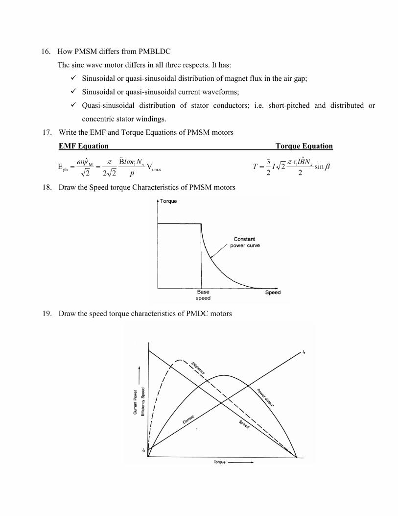
19. Draw the speed torque characteristics of PMDC motors