Embed Size (px)
Citation preview

Permissible Parameter Ranges of AccessHole Geometries for WUF-W Connections
Sang Whan Han,a) M.EERI, and Nam Hun Kima)
The welded unreinforced flange-welded web (WUF-W) connection is one ofseven prequalified connections for special moment frames (SMF) specified inAISC 358-10 (2010). Previous studies reported that the cyclic behavior ofWUF-W connections was strongly affected by weld access hole geometry, andsome WUF-W connections did not satisfy the requirements for SMF connections.For investigating in detail the effect of access hole configurations on the cyclicbehavior ofWUF-W connections, this study conducts three-dimensional nonlinearfinite element analyses. This study shows that the seismic behavior of WUF-Wconnections are strongly affected by two configuration parameters, access holeslope and length of flat portion. To satisfy the requirement for SMF connections,this study proposes a range of the access hole slope and length of flat portion forWUF-W connections considering different span-to-depth ratios, beam depths, andmaterial types. [DOI: 10.1193/060716EQS092M]
INTRODUCTION
Moment frames have been used as seismic force resisting systems in areas of highseismicity. Prior to the 1994 Northridge and 1995 Kobe earthquakes, steel moment frameswere expected to sustain large seismic loads owing to their inherent deformation and energydissipation capacities. However, unexpected brittle fracture occurred in steel moment frameconnections in many buildings during those earthquakes (Youssef et al. 1995, Malley 1998).Many studies were performed to investigate the causes of the unsatisfactory failure of themoment connections and to give solutions (Stojadinovic et al. 2000, Sotirov et al. 2000, Lucoand Cornell 2000, Lee and Foutch 2002, Han et al. 2007). Due to the enormous previousworks, new moment connections were developed, which demonstrated the ability to attainlarge drift angles when subjected to a prescribed quasi-static simulated seismic loadings(FEMA-350 2010). It is left to be determined whether these connections can in fact withstandlarge earthquakes.
In AISC 358-10 (AISC 2010), seven prequalified connections for special moment frames(SMF) are specified. The welded unreinforced flange-welded web moment connection(WUF-W connection) is one of seven prequalified SMF connections, which is an all-weldedmoment connection. Previous pioneering experimental studies showed that WUF-Wconnections had excellent connection performance, and satisfied the drift capacity forSMF connections specified by AISC 341-10 (AISC 2010) which should be 4% orlarger (Ricles et al. 2000, Dexter et al. 2004, Lee et al. 2005a, 2005b). Analytical studieswere also conducted for WUF-W connections (Chi et al. 1997, El-Tawil et al. 1998,
a) Hanyang University, Seoul 133-791, Korea
Earthquake Spectra, Volume 33, No. 2, pages 687–707, May 2017; © 2017, Earthquake Engineering Research Institute687

Lu et al. 2000, Mao et al. 2001). In those studies, it was shown that the connection behaviorwas strongly affected by access hole configuration.
Han et al. (2014) also conducted experimental tests using five WUF-W connectionspecimens. The specimens had access holes with a steep slope (21º). Unlike the resultsfrom the previous experimental studies, they reported that some WUF-W connections didnot satisfy the requirements for SMF connections even though the connections were designedand detailed according to AISC 358-10 and AISC 341-10 (AISC 2010). Particularly,WUF-W connections with a beam depth of 890 mm failed before completing a loadingcycle at a drift ratio of 4%. One of the major differences between the specimens testedby Han et al. (2014) and those used in former studies (Ricles et al. 2000, Lee et al.2005a, b) was access hole geometry.
The details for theWUF-Wmoment connection is illustrated in Figure 1. Since the plastichinge occurs at the face of the column in WUF-W connections, AISC 358-10 (AISC 2010)specifies stringent detailing and welding requirements. The column-to-beam strength ratiofor SMFs should be greater than 1.0 (Section E3.4a of AISC 341-10). The access hole in SMFconnections should satisfy the geometric requirements specified in AWS D1.8/D1.8M(AWS 2009).
Figure 1. Details of the WUF-W connections.
688 S. W. HAN AND N. H. KIM

In order to investigate the cause of the unsatisfactory performance seen for someWUF-Wconnections, this study performs nonlinear three-dimensional (3-D) finite element analyses(FEA). This study also proposes ranges for access holes configuration parameters in WUF-Wconnections to improve their seismic performance.
SUMMARY OF PREVIOUS EXPERIMENTS ON WUF-W CONNECTIONS
According to AISC 358-10, the WUF-W moment connections was classified as prequa-lified SMF connections owing to pioneering experimental works of two research groups(Ricles et al. 2000, Ricles et al. 2002, Lee et al. 2005a, b). They tested 24WUF-W connectionspecimens in order to investigate the seismic behavior of WUF-W connections. Ricles et al.(2002) conducted experimental tests with eleven WUF-W connections having modifiedaccess hole geometries as proposed by Mao et al. (2001). The ratio of span to depth ofthe beams (l∕d) was 9.8. The specimens were made from high toughness weld metal.They demonstrated that all tested specimens had excellent seismic performance and produceda drift ratio of at least 0.04 prior to failure. Lee et al. (2005a, b) tested WUF-W connections toinvestigate the effects of the doubler plate, continuity plate and weak panel zone. All specimenssatisfied the rotation requirements for SMF connections. The access holes of the specimenswere similar to those proposed by Mao et al. (2001). The slope access hole slope was 15°.Figure 2a and 2b illustrates the access hole configurations of the tested specimens.
Han et al. (2014) also tested four WUF-W connection specimens (D700-S, D700-B,D900-S and D900-B). Specimens D700-S and D700-B had a beam depth of 692 mm,whereas the beam depth of the D900-S and D900-B was 890 mm. It is noted that l∕dfor D700 and D900 specimens were 9.97 and 7.75, respectively. Note that the panelzone strength of D700-S (D900-S) was larger than that of D700-B (D900-B).
All specimens were designed and detailed according to AISC 341-10 and AISC 358-10.One of the main differences between specimens tested by Han et al. (2014) and previousstudies was access hole geometry (Figure 2c and 2d). All specimens tested by Han et al.(2014) had access holes steeper (21º) than those from the previous studies. The limitingvalue of the access hole slope is specified as 25º (AWS D1.8/D1.8M). They reportedthat specimens D700-S and D700-B completed two cycles at a drift ratio of 4%, whichis required for SMF connections in AISC 341-10 (AISC 2010), whereas D900-S andD900-B were unable to complete one cycle at a drift ratio of 4%. Figure 3 shows hystereticcurves from these specimens.
Figure 2. Access hole geometries and sizes of WUF-W connection specimens.
PERMISSIBLE PARAMETER RANGES OF ACCESS HOLE GEOMETRIES FORWUF-WCONNECTIONS 689

To investigate the effect of access hole slope, Han et al. (2016) also conducted an experi-mental test using a WUF-W connection specimen (D900-S-A) that was identical to D900-Sexcept that D900-S-A had an access hole with a slope of 13º (Figure 2e) rather than 21º. Asshown in Figure 3e, D900-S-A had total and plastic drift capacities of 5% and 4.4%,
Figure 3. Hysteretic and backbone curves of WUF-W connections.
690 S. W. HAN AND N. H. KIM

respectively, which satisfied the requirement for SMF connections. Figure 3f shows thebackbone curves of the specimens extracted from the hysteretic curves.
FINITE ELEMENT MODEL AND ANALYSIS
This study estimates the effect of access hole geometry on connection behavior by con-ducting nonlinear 3-D FEA. Commercial software ABAQUS/CAE and ABAQUS/Standardare used (Hibbitt et al. 2011). For constructing FE models, the same dimensions andsupport conditions are used as those used for the experimental testing of WUF-W connections(Han et al. 2014).
Figure 4 shows the test setup and FEmodel. To laterally restrain the beam, the out-of-planedeflection is set to zero in the FE model at the same location of the lateral support in the testsetup. The same loading history is used for analysis as was used for experiments and thedisplacement controlled cyclic loading is applied at the beam end. It should be noted thatthe loading history follows the SAC loading protocol (Krawinkler et al. 2000).
The results from FE analysis depend on the type and size of the mesh used. A three-dimensional FE model with an eight-node brick element is used. In ABAQUS, three differentbrick elements are available: the regular brick element with standard integration (C3D8), thebrick element with an incompatible deformation mode (C3D8I), and the brick element withreduced integration (C3D8R). Using element C3D8 that is the first order fully integratedelement, a significant increase in stiffness could occur due to shear locking. The firstorder integrated element C3D8I with incompatible modes was developed to improve thebending modes (Hibbitt et al. 2010), but the shear locking problem could not be removedcompletely. Element C3D8R is the first-order reduced-integration element that eliminatesshear locking so that this element can be used for modeling a member dominated by flexure.
Figure 4. Test setup, loading cycles, and FE model.
PERMISSIBLE PARAMETER RANGES OF ACCESS HOLE GEOMETRIES FORWUF-WCONNECTIONS 691

Since element C3D8R requires reduced integration, this element requires less computationthan elements C3D8 and C3D8I. However, hourglass mode is a concern for this element,resulting in zero energy mode. This problem can be solved by using multiple elementsthrough the thickness. Considering the computational efficiency and accuracy of elementC3D8R for the analysis of flexure dominated members, this study uses element C3D8Rfor modeling WUF-W connections.
Ricles et al. (2000) reported that analysis results using element C3D8R were moresensitive to mesh sizes than those made using elements C3D8I and C3D8. However,with an adequate mesh size, FE analyses using C3D8R can produce accurate results(El-Tawil et al. 1998, Lu et al. 2000). To determine the adequate mesh size for theWUF-W connections, a sensitivity study is conducted according to the mesh size of elementC3D8R. Figure 5 shows lower part of WUF-W connections.
The distribution of von Mises stresses is plotted along the beam flange at the column facein Figure 5f according to mesh sizes through the thickness of the column and beam flanges.The von Mises stresses are calculated using Equation 1:
EQ-TARGET;temp:intralink-;e1;41;444σef f ¼ffiffiffiffiffiffiffiffiffiffiffiffiffi2
3SijSij
r(1)
where Sij is the deviatoric stress components (Sij ¼ σij þ σmδij) with global coordinates(i, j), σij is the Cauchy stress components, δij is the value of the Kronecker’s delta, and
Figure 5. Distribution of von Mises stress according to mesh sizes.
692 S. W. HAN AND N. H. KIM

σm is the hydrostatic stress. Figure 5f shows that the stress distribution obtained using onelayer of elements through the thickness of the flanges is significantly different from the dis-tributions obtained using two or more mesh layers. It is also found that the discrepancyamong the stress distributions is negligible when the number of mesh layers is greaterthan or equal to 4. Thus, this study uses four mesh layers throughout the thickness ofthe flanges. To prevent the hourglass mode at the welding area for the beams and columns,heat affected zones, and regions near the access holes, the mesh size is also subdivided asshown in Figure 5d. A large deformation analysis is conducted, using “Nlgeom” option pro-vided in the ABAQU software, wherein large plastic deformations near access holes and localbuckling can be accurately predicted.
VERIFICATION OF THE FE MODEL
To verify the accuracy of the FE model used in this study, the cyclic behavior of theD700-S, D700-B, D900-S, D900-B, and D900-S-A specimens are simulated using FEA.The material properties for the FE models are obtained from the results of coupon testsconducted by Han et al. (2014, 2016). Figure 6 presents the stress-strain (σ � ε) relationsfor the D900-S specimen obtained from the coupon tests. Strains were measured usingelongations between two distinctive points with a certain gauge length in the specimen(Figure 6c). Coupon tests were conducted with high performance UTM in the ResearchInstitute of Industrial Science and Technology (RIST), POSCO in Korea, which is ableto automatically record elongations in the gauge length. The gauge length for SM 490and SS400 coupons were 50 mm and 200 mm, respectively. Since FE modeling inABQUS software requires the true stress and true plastic strain (σtrue, εpl), the stress-straincurve in Figure 6 is modified with Equations 2 and 3:
EQ-TARGET;temp:intralink-;e2;62;343σtrue ¼ σð1þ εÞ (2)
EQ-TARGET;temp:intralink-;e3;62;306εpl ¼ lnð1þ εÞ � σ
E(3)
where E is the elastic modulus (205GPa). The CJP welded portion is explicitly modeledusing the properties of weld metal E71T-1C used for WUF-W connection specimens.
Figure 6. Stress-strain curves for steel materials.
PERMISSIBLE PARAMETER RANGES OF ACCESS HOLE GEOMETRIES FORWUF-WCONNECTIONS 693

The yield strength, tensile strength, elongation, and Charpy V-notch toughness ofE71T-1C are 400MPa, 650MPa, 22%, and 27J at �18°C, respectively, which were providedby the manufacturer. A Poisson ratio of 0.3 is used in the FEA. It is, however, noted that thematerial properties of HAZ are not considered.
To consider cyclic strain hardening characteristic, this study adopts cyclic materialcoupon tests conducted by Kaufmann et al. (2001) for steel types A36 and A572 GR50,which are similar to the SS400 and SM 490 steels used by Han et al. (2004). The specifiedminimum yield strengths (Fy) of A36 and A572 Grade 50 steels, and SS400 and SM 490steels are 250 and 345 MPa, and 240 and 330 MPa, respectively. For FE models, theplastic range of the material is idealized by combining isotropic and kinematic hardenings.In the ABAQUS software, von Mises yield surface size (σ0) is used as a combinedhardening model to represent the combination of isotropic and kinematic hardenings.The coefficients for the combined hardening model are determined to accurately simulatecyclic strain hardening behavior obtained from cyclic material coupon tests with thehardening model.
Figure 3 shows the hysteretic curves (dotted lines) obtained via FEA, which accuratelymatch the experimental curves. Table 1 summarizes the maximum shear force andinitial stiffness values determined from the hysteretic curves. The initial stiffness istaken as the slope of a line that connects the two points at the positive and negativepeak drifts on the load-displacement curve at 0.25% drift (peak-to-peak stiffness).The error is calculated using Equation 4, which is defined as the deviation in the FEAresults (xFEA) from the results (xtest) of experimental tests. As summarized in Table 1, errorsassociated with initial stiffness and maximum shear force are within 5.0% and 7.5%,respectively.
EQ-TARGET;temp:intralink-;e4;41;334errorð%Þ ¼ xFEA � xtestxtest
� 100 (4)
Figure 7 shows cumulative dissipated energy at each loading cycle calculated usingthe hysteretic curves in Figure 3. It is also observed that the cumulative dissipated energiesobtained from FEA results are almost the same as those obtained from experiments.Figure 8a shows specimen D700-S at 5% drift ratio, and Figure 8b showsspecimen D900-S at 3% drift ratio. Buckling and local kinking are considered in FEA
Table 1. Initial stiffness and maximum shear force
Specimen
Initial stiffness (kN/mm) Maximum shear force (kN)
Experiment FEA Error (%) Experiment FEA Error (%)
D700-B 14.17 14.07 0.7 741.6 690.3 6.9D700-S 14.05 14.73 4.8 721.7 690.4 4.3D900-B 26.13 26.37 0.9 1,169.8 1,088.8 6.9D900-S 27.74 27.46 1 1,220.4 1,151.5 5.6D900-S-A 29.15 28.79 1.2 1,144.2 1059 7.4
694 S. W. HAN AND N. H. KIM

by applying initial imperfections (Atashzaban et al. 2015). Using ABAQUS 6.10, an“imperfection” option can be used to introduce a geometric imperfection into a modelfor post-buckling analyses.
As shown in Figure 8, the shape and location of buckling and the area of yielding aresimilarly predicted via FEA. In Figure 8, the distribution of von Mises stresses is plotted onthe deformed configuration of the connections.
Figure 7. Cumulative dissipated energy obtained from FEA and tests.
Figure 8. Deformed WUF-W specimens: (a) D700-S at 5% drift ratio; (b) D900-S at 3% driftratio.
PERMISSIBLE PARAMETER RANGES OF ACCESS HOLE GEOMETRIES FORWUF-WCONNECTIONS 695

PREDICTION OF WUF-W CONNECTION FRACTURE USING FEA
In order to accurately estimate the rotation capacity of WUF-W connections using FEmodels, it is important to predict the incidence of connection fracture. However, it iscomplex to construct an explicit model for predicting the incidence of fracture by adoptingfracture mechanics, particularly for members with complex configurations such as WUF-Wconnections. In this study, cracks are not explicitly modeled to predict the behavior andstrength of WUF-W connections having crack propagation using fracture mechanics. Toavoid difficulties in predicting connection fracture using FE models, this study adoptsthe rupture index (RI) to predict the incidence of fracture in WUF-W connections, whichis capable of considering both equivalent plastic strain (PEEQ) and ductile failure strain (εf ).
The rupture index is calculated using Equation 5, which was used by El-Tawil et al.(1998) for proposing optimal access hole geometry.
EQ-TARGET;temp:intralink-;e5;41;481RI ¼ aPEEQ∕εy
εf¼ PEEQ∕εy
exp
��1.5 σm
σef f
� (5)
EQ-TARGET;temp:intralink-;e6;41;412εf ¼ a expð�1.5σmσef f
Þ (6)
EQ-TARGET;temp:intralink-;e7;41;373σm ¼ � 1
3traceðσijÞ (7)
EQ-TARGET;temp:intralink-;e8;41;336σef f ¼ffiffiffiffiffiffiffiffiffiffiffiffiffi2
3SijSij
r(8)
The PEEQ index is calculated using Equation 9:
EQ-TARGET;temp:intralink-;e9;41;282PEEQ ¼ffiffiffiffiffiffiffiffiffiffiffiffi2
3εpijε
pij
r(9)
where εpij is the plastic strain component of global coordinates (i, j), εy is the yield strainobtained from the coupon test, σef f is the von Mises stress, σm is the hydrostatic stress, andSij are the deviatoric stress component (Hancock and Mackenzie 1976). The previous studyreported that fracture initiated on the beam flange near access hole toe and heat affected zone,HAZ (Figure 9; Han et al. 2014). In this study, the RI is estimated at the weld access hole toeand HAZ in the beam flanges of each specimen using the results of FEA. Thisprocess is repeated until reaching the last tested loading cycle.
Figure 10 shows the rupture index from five WUF-W connection specimens. Allspecimens are fractured specimens except for specimen D900-S-A. The RI value calculatedat the last loading stage for fractured specimens is defined as RI connection fractureVariations in RI values at connection fracture is small. The coefficient of variation isonly 3.7%. In this study, RI value of 1,150 is used as a limiting value to detect the incidence
696 S. W. HAN AND N. H. KIM

of connection fracture, that is, when the RI exceeds 1,150, connection fracture will occur. It isnoted that the RI value for specimen D900-S-A is less than 1,150 at the last loading stage, andno fracture is expected to occur. It is confirmed that this specimen did not experience fractureduring the test.
EFFECT OF ACCESS HOLE CONFIGURATION ON CONNECTION BEHAVIOR
The effect of access hole configuration parameters on the behavior of WUF-W connectionsis studied. In AWS D1.8/D1.8M, six configuration parameters and their permissible ranges are
Figure 9. Locations of fracture and monitoring of RI.
Figure 10. Rupture Index of WUF-W connections according to drift ratios.
PERMISSIBLE PARAMETER RANGES OF ACCESS HOLE GEOMETRIES FORWUF-WCONNECTIONS 697

specified for SMF connections. These six configuration parameters are listed in Figure 11; theyare the length of the flat portion (L), overall length (T), access hole height (H), radius of accesshole (R), bevel (B), and access hole slope (S).
For simplicity, in this study, the bevel (B) and radius of the access hole (R) are assumed tobe 30° and 10 mm, respectively. Since access hole height and overall length are dependentparameters, only overall length is considered as a variable. Therefore, overall length (T), accesshole slope (S), and the length of the flat portion (L) are defined as the main variables in thisstudy. The ranges for overall length (T) and length of the flat portion (L) permitted by AWSD1.8/D1.8M (AWS 2009) are 64–80 mm and 17.3–34.5 mm, respectively. For the access holeslope, AWS D1.8/D1.8M specifies only the maximum value, which is 25°. In this study, thelower bound of the access hole slope is assumed to be 13°, which was used for specimen T1and D900-S-A (Ricles et al. 2002, Han et al. 2015). Although the radius of access holes affectthe connection behavior (El-Tawil et al. 1998), this parameter is not considered in this study.
To estimate the effect of the three configuration parameters on seismic behavior ofWUF-W connections, three values for each parameter are considered: minimum, intermediateand maximum values within the ranges permitted in AWS D1.8/D1.8M (Figure 11). SpecimenD900-S is modeled considering 27 ð¼3ðLÞ � 3ðSÞ � 3ðTÞÞ different configurations for theaccess holes.
Figure 12 shows the distribution of von Mises stresses for the six WUF-W connectionswith different access hole geometries at a 3% drift ratio. As shown in Figure 12a and b forspecimens S13-L26-T72 and S25-L26-T72, the maximum stress increases (520 MPaversus 583 MPa) as access hole slope (S) increases from 13° to 25°. Note that specimensS13-L26-T72 and S25-L26-T72 have the same length of the flat portion (L) and overalllength (T), which are 26 mm and 72 mm, respectively. With an increase in S, the areaof maximum stress widens and migrates towards the access hole toe. This indicates thatthe potential of beam flange fracture goes higher as access hole slope (S) increases.
In Figure 12c and d, the distribution of von Mises stress is plotted according L.The maximum stresses of specimens S19-L18-T72 (L ¼ 18mm) and S19-L34-T72
Figure 11. Representative values for configuration parameters.
698 S. W. HAN AND N. H. KIM
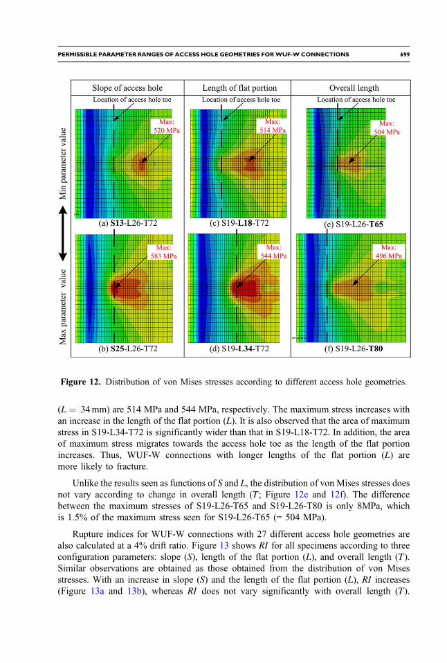
(L ¼ 34mm) are 514 MPa and 544 MPa, respectively. The maximum stress increases withan increase in the length of the flat portion (L). It is also observed that the area of maximumstress in S19-L34-T72 is significantly wider than that in S19-L18-T72. In addition, the areaof maximum stress migrates towards the access hole toe as the length of the flat portionincreases. Thus, WUF-W connections with longer lengths of the flat portion (L) aremore likely to fracture.
Unlike the results seen as functions of S and L, the distribution of von Mises stresses doesnot vary according to change in overall length (T ; Figure 12e and 12f). The differencebetween the maximum stresses of S19-L26-T65 and S19-L26-T80 is only 8MPa, whichis 1.5% of the maximum stress seen for S19-L26-T65 (= 504 MPa).
Rupture indices for WUF-W connections with 27 different access hole geometries arealso calculated at a 4% drift ratio. Figure 13 shows RI for all specimens according to threeconfiguration parameters: slope (S), length of the flat portion (L), and overall length (T).Similar observations are obtained as those obtained from the distribution of von Misesstresses. With an increase in slope (S) and the length of the flat portion (L), RI increases(Figure 13a and 13b), whereas RI does not vary significantly with overall length (T).
Figure 12. Distribution of von Mises stresses according to different access hole geometries.
PERMISSIBLE PARAMETER RANGES OF ACCESS HOLE GEOMETRIES FORWUF-WCONNECTIONS 699

Thus, this study proposes a range of access hole slopes (S) and lengths of the flat portion (L)that there will be no connection fracture until a 4% drift ratio is reached.
EFFECT OF SPAN-TO-DEPTH RATIOS AND MATERIAL TYPES
Even though specimen D700-S and D900-S had the same access hole configuration witha access hole slope of 21º, specimen D700-S with span-to-depth ratio (l∕d) of 9.97 and beamdepth of 692 mm satisfied the requirement for SMF connections, but specimen D900-S withl∕d of 7.76 and beam depth of 890 mm did not satisfy the SMF requirement. Severalresearches investigated the effect of beam depth (d) and span-to-depth ratio on the cyclicbehavior of WUF-B connections. Roeder and Foutch (1996) reported that the flexuralductility of WUF-B (bolted web) connections was reduced by increased beam depth.Shin and Engelhardt (2013) conducted cyclic tests with WUF-B (bolted web) connectionspecimens. They reported that the cyclic behavior of WUF-B connection specimens wasaffected by l∕d.
In order to investigate the influence of d and l∕d on the cyclic behavior of WUF-Wconnections, six WUF-W connections are considered, which have two different beamdepths (692 mm and 890 mm) and three different span-to-depth ratios (7, 8.5, and 10).All connections have the same access hole configuration with an access hole slope of25º. Cyclic curves for all connections are simulated using FEA, and the incidence of fractureis predicted with rupture index.
Figure 14 shows the cyclic curves of six WUF-W connections. It can be seen that the driftcapacity of WUF-W connections varies according to l∕d. It is also observed that WUF-Wconnections with different beam depths have different drift capacities even though they havethe same span-to-depth ratio and access hole configuration.
This study also investigates the influence of different material types on the cyclicbehavior of WUF-W connections. For this purpose, four WUF-W connections are considered(D700-M1, D900-M1, D700-M2, D900-M2). All connections are assumed to have the same
Figure 13. Rupture Index according to major configuration variables.
700 S. W. HAN AND N. H. KIM

access hole configuration with an access hole slope of 25º. The beams and columns in speci-mens D700-M1 and D900-M1 are assumed to be made of SS400 and SM490, respectively,whereas for both columns and beams in specimens D700-M2 and D900-M2, A572 Grade 50steel is used. Table 2 summarizes yield strength and maximum elongation obtained fromcoupon tests for A572 Grade 50 and SS400 steels. It is noted that the maximum strainand yield strength of A572 Grade 50 steel has 16% and 8% larger than those of SS400steel, respectively. Input values for A572 Grade 50 steel required in the ABAQUS softwareare determined based on cyclic coupon test results conducted by Kauffman et al. (1999).For specimens D900-M1 (M2) and D700-M1 (M2), span-to-depth ratios are set to 7.0and 10.0, respectively.
Figure 15 shows the cyclic curves of specimens D900-M1 (M2) and D700-M1 (M2)simulated using FEA. The strength and drift capacity of specimen D900-M2 are 6.2%and 33% larger than those of specimen D900-M1, respectively. Similar observation ismade for specimens D700-M1 and D700-M2. Therefore, the cyclic behavior of WUF-Wconnections is also affected by material types. This indicates that when the permissableranges of access hole parameters are determined, the effect of span-to-depth ratio (l∕d),beam depth (d), and material type should be considered.
Figure 14. Hysteretic curves of six WUF-W connections with different span-to-depth ratios.
Table 2. Summary of properties of different steel types
Steel typeYield strength,
Fy (MPa)Ultimate strength,
Fy (MPa)Maximum strain,
εf (%)
SS400 333.6 437.0 28.0SM490 380.1 571.8 26.7A572 Gr.50 361.2 496.4 32.5
PERMISSIBLE PARAMETER RANGES OF ACCESS HOLE GEOMETRIES FORWUF-WCONNECTIONS 701

DETERMINATION OF ACCESS HOLE PARAMETER RANGES
According to AISC-341 (AISC 2010), SMF connections should sustain a drift ratio of 4%.To propose adequate parameter ranges (S and L) for the access holes in WUF-W connections,WUF-W connections with different beam depths (692 mm and 890 mm), span-to-depth ratios,and material types are considered.
For a connection with specific l∕d, d, and material type, 25 ð¼5� 5Þ access holeconfigurations of access hole slopes (5) and lengths of the flat portions (5) are considered;therefore, FEA are conducted twenty five times for the connection with 25 different accesshole configurations, and RI values for the connections are estimated at a drift ratio of 4%.Since this study considers two different material types (SS400 steel for beams and SM490steel for columns, and A572 Grade 50 steel for beams and columns) (2), two differentbeam depths (2), and three span-to-depth ratios (3), a total of 300 WUF-W connectionsð¼5� 5� 2� 2� 3Þ are modeled and analyzed. Figure 16a and 16b show the RI valuesof WUF-W connections made of SS400 steel for beams and SM490 steel for columnswith different beam depths and span-to-depth ratios.
In Figure 16a, WUF-W connections have l∕d of 9.98 and d of 692 mm, whereasconnections in Figure 16b have l∕d of 7.75 and d of 890 mm. In this study, when theRI value of a WUF-W connection is smaller than 1,150, the connection is considered tosatisfy the requirement for SMF connections. The ranges of slopes (S) and lengths of the
Figure 15. Hysteretic curves of four WUF-W connections with different material types:(a) D900-M1, (b) D900-M2, (c) D700-M1, (d) D700-M2.
702 S. W. HAN AND N. H. KIM

flat portion (L) for connections D700-S ðl∕d ¼ 9.95Þ and D900-S ðl∕d ¼ 7.68Þ made ofSS400 and SM 490 are plotted in Figure 17 which are simply the projection of Figure 16aand 16b onto the domains of S and L.
In this figure, the actual values of S and L for the tested WUF-W connection specimens(D700-B and D700-S, and D900-B, D900-S, and D900-S-A) are also marked. As expected,tested specimens D700-B, D700-S and D900-S-A have combinations of S and L within thesafe domain (Figure 17a and 17b), whereas the combinations of S and L of tested specimensD900-S and D900-B are located within the failure domain. In Figure 17, the ranges for S andL permitted by AWS D1.8/D1.8M (AWS 2009) are also plotted using dashed lines. It isobserved that many combinations of S and L permitted by AWS D1.8/D1.8M are locatedwithin the failure domain.
Figure 16. RI values of WUF-W connections with different combinations of S and L.
Figure 17. Adequate ranges of access hole slopes (S) and lengths of the flat portion (L).
PERMISSIBLE PARAMETER RANGES OF ACCESS HOLE GEOMETRIES FORWUF-WCONNECTIONS 703

For various combinations of span-to-depth ratios, depths, material types, similarfigure are plotted as shown in Figure 18. In this figure, a solid line denotes a limitstate between safe and failure domains (RI ¼ 1,150) for WUF-W connections withspecific l∕d, d, and material type, which is represented by a linear equation. Thecoefficients of the linear equation are easily determined from Figure 18. Based oncoefficients of linear limit state equations determined for WUF-W connections withvarious l∕d, d, and material type in Figure 18, following equations are obtained,which can be used to conveniently check whether or not a combination of selected Sand L values is located within the safe domain. In other words, when the combinationof selected values for S and L satisfies the following equations, they are considered to bewithin permissible ranges.
In the case of WUF-W connections with a beam depth of 692 mm,
1. For connections made of SS400 for beams and SM490 for columns:
EQ-TARGET;temp:intralink-;e10;41;4680.78Lþ 1.12S < 35.15þ l∕d (10)
Figure 18. RI values of WUF-W connections with different beam depths, span-to-depth ratios,and material types.
704 S. W. HAN AND N. H. KIM

2. For connections made of A572 Grade 50 (or A992) for beams and columns:
EQ-TARGET;temp:intralink-;e11;62;6270.38Lþ 0.54S < 13.31þ l∕d (11)
In the case of WUF-W connections with a beam depth of 890 mm,3. For connections made of SS400 for beams and SM490 for columns:
EQ-TARGET;temp:intralink-;e12;62;5530.34Lþ 1.39S < 28.87þ l∕d (12)
4. For connections made of A572 Grade 50 (or A992) for beams and columns:
EQ-TARGET;temp:intralink-;e13;62;5000.41Lþ 1.70S < 37.88þ l∕d (13)
Equations 12 and 13 may be conservatively used for WUF-W connections made ofSS400 for beams and SM490 for columns and A572 Grade 50 for beams and columns,respectively, when the beam depth of the connections is smaller than 890 mm. Forpractical purposes, the combination of S and L need not be beyond the ranges specifiedin AWS D1.8/D1.8M. For other steel grades, caution should be made for using theabove equations.
CONCLUSION
This study conducted FEA to find the cause of early fracture on pre-qualified WUF-Wconnections designed and detailed according to AISC-358 and AISC-341 (AISC 2010).In addition, adequate ranges for access hole configuration parameters were proposed.The FE models for WUF-W connections were calibrated to accurately simulate theexperimental test results. Based on this study, conclusions and recommendations weremade as follows:
1. It is shown that the hysteretic behaviors of WUF-W connections were accuratelysimulated using FEA. Based on FEA results of WUF-W connections, one of themain causes of fracture in WUF-W connections is access hole geometry.
2. This study proposed a limiting value for rupture index (=1,150) which can beused to predict the incidence of fracture in beam flanges. It was observed thatthis limiting value, obtained at connection fracture, is nearly constant for allfractured specimens.
3. It was observed that the slope of the access holes (S) and the length of the flatportions (L) affect the connection behavior significantly, whereas the influenceof overall length (T) on the connection behavior is small. Thus, this study proposedranges for S and L. It is also shown that many combinations of S and L permitted byAWS D1.8/D1.8M are located within the failure domain.
4. This study also observed that span-to-depth ratios, beam depths and materialtypes also affect the cyclic behavior of WUF-W connections along with assesshole geometry. In this study, permissible ranges of S and L values were determined,which are able to account for the effect of l∕d, d, and material types.
PERMISSIBLE PARAMETER RANGES OF ACCESS HOLE GEOMETRIES FORWUF-WCONNECTIONS 705

5. To check the adequacy of a selected combination of S and L values, simpleequations were proposed for WUF-W connections with beam depths of 692 mmand 890 mm considering different span-to-depth ratios and material types. Theequation for a beam depth of 890 mm may be conservatively used for WUF-Wconnections with beam depths of 890 mm or shallower.
ACKNOWLEDGMENTS
Authors would like to acknowledge the financial supports provided by the NationalResearch Foundation of Korea (No. 2014R1A2A1A11049488). The valuable commentsoffered by anonymous reviewers are greatly appreciated.
REFERENCES
American Institute of Steel Construction (AISC), 2010. Seismic Provisions for Structural SteelBuildings, AISC/AISC 341-10, Chicago, IL.
American Institute of Steel Construction (AISC), 2010. Prequalified Connections for Special andIntermediate Steel Moment Frames for Seismic Applications, AISC/AISC 358-10, Chicago, IL.
Atashzaban, A., Hajirasouliha, I., Jazany, R. A., and Izadinia, M., 2015. Optimum drilled flangemoment resisting connections for seismic regions., J. Constr. Steel. Res. 112, 325–338.
American Welding Society (AWS), 2009. Structural Welding Code-Seismic Supplement, AWSD1.8/D1.8M, Miami, FL.
Chi, W. M., Deierlein, G. G., and Ingraffea, A. R., 1997. Finite Element Fracture MechanicsInvestigation of Welded Beam-Column Connections, SAC Joint Venture, ReportNo. SACIBD-97/05, Sacramento, CA.
Dexter, R. J., Hajjar, J. F., and Lee, D., 2004. Effect of column stiffener detailing and weldfracture toughness on the performance of welded moment connections, connections insteel construction V: Innovations in steel connections, Amsterdam, the Netherlands, EuropeanConvention for Constructional Steelwork, Amsterdam.
El-Tawil, S., Mikesell, T., Vidarsson, E., and Kunnath, S. K., 1998. Strength and Ductility of FRWelded-Bolted Connections. SAC Joint Venture, Rep. No. SAC/BD-98/01, Sacramento, CA.
Han, S. W., Kwon, G. U., and Moon, K. H., 2007. Cyclic behavior of post-Northridge WUF-Bconnections, J. Constr. Steel. Res. 63, 365–374.
Han, S. W., Moon, K. H., and Jung, J., 2014. Cyclic performance of welded unreinforcedflange-welded web moment connections, Earthq. Spectra 30, 1663–1681.
Han, S. W., Jung, J., and Ha, S. J., 2016. Seismic performance of WUF-W moment connectionsaccording to access hole geometries, Earthq. Spectra 32, 909–926.
Hancock, J. W., and Mackenzie, A. C., 1976. On the mechanisms of ductile failure inhigh-strength steels subjected to multi-axial stress-states, J. Mech. Phys. Solids. 24, 147–160.
Dassault Systemes, 2010. ABAQUS Analysis User’s Manual, Providence, RI.Kaufmann, E. J., 2001, Characterization of Cyclic Inelastic Strain Behavior on Properties of
A572 Gr.50 and A913 Gr. 50 Rolled Sections, ATLSS Rep. No. 01-13, Bethlehem, PA.Krawinkler, H., Gupta, A., Medina, R., and Luco, N., 2000. Loading Histories for Seismic
Performance Testing of SMRF Components and Assemblies, SAC Joint Venture, Rep.No. SAC/BD-00/10, Sacramento, CA.
706 S. W. HAN AND N. H. KIM

Lee, D., Cotton, S. C., Hajjar, J. F., Dexter, R. J., and Ye, Y., 2005a. Cyclic connectionsreinforced by alternative column stiffner details I: panel zone behavior and doubler platedetailing, AISC Engineering Journal 42, 189–214.
Lee, D., Cotton, S. C., Hajjar, J. F., Dexter, R. J., and Ye, Y., 2005b. Cyclic connectionsreinforced by alternative column stiffner details II: panel zone behavior and doubler platedetailing, AISC Engineering Journal 42, 215–238.
Lee, K., and Foutch, D. A., 2002. Performance evaluation of new steel frame buildings forseismic loads, Earthq. Eng. Struct. Dyn. 31, 653–670.
Luco, N., and Cornell, C., 2000. Effects of connection fractures on SMRF seismic drift demands,J. Struct. Eng. 126, 127–136.
Lu, L. W., Ricles, J. M., and Fisher, J. W., 2000. Critical issues in achieving ductile behavior ofwelded moment connections, Journal of Constructional Steel Research 55, 325–341.
Malley, J., 1998. SAC steel project: Summary of phase 1 testing investigation results.Engineering Structures 20, 300–309.
Mao, C., Ricles, J., Lu, L. W., and Fisher, J., 2001. Effect of local details on ductility of weldedmoment connections, ASCE Journal of Structural Engineering 127, 1036–1044.
Ricles, J. M., Fisher, J. W., Lu, L. W., and Kaufmann, E. J., 2000. Development of improvedwelded moment connections for earthquake-resistant design, ASCE Journal of StructuralEngineering 58, 565–604.
Ricles, J. M., Mao, C., Lu, L. W., and Fisher, J. W., 2002. Inelastic cyclic testing of weldedunreinforced moment connections, ASCE Journal of Structural Engineering 128, 429–440.
Roeder, W. R., and Foutch, D. A., 1996. Experimental results for seismic resistant stee momentframe connections, J. Struct. Eng. 122, 581–588.
SAC Joint Venture, 2000. Recommended Seismic Design Criteria for New Steel Moment FrameBuildings, FEMA 350, Richmond, CA.
Shin, S., and Engelhardt, M., 2013. UT06, Steel Moment Resisting Frame with WUF‐WConnections and Strong Panel Zone, Network for Earthquake Engineering Simulation(distributor), Data Set, DOI:10.4231/D3FJ29C60.
Sotirov, P., Rangelov, N., Ganchev, O., Georgiev, T., Milev, J., and Petkov, Z., 2000. Moment-resisting connections of steel frames in seismic area, Design and Reliability, E&FN SPON,New York.
Stojadinovic, B., Goel, S. C., Lee, K. H., Margarian, A. G., and Choi, J. H., 2000. Parametric testson unreinforced steel moment connections, J. Struct. Eng. 126, 40–49.
Youssef, N. F., Bonowitz, D., and Gross, J. L., 1995. A Survey of Steel Moment-Resisting FrameBuildings Affected By the 1994 Northridge Earthquake, National Technical InformationService (NTIS), Rep. No. NISTIR 5625, Gaithersburg, MD.
(Received 7 June 2016; accepted 26 December 2016)
PERMISSIBLE PARAMETER RANGES OF ACCESS HOLE GEOMETRIES FORWUF-WCONNECTIONS 707