Embed Size (px)
Citation preview
PERMSELECTIVE MEMBRANES FOR THE REMOVAL OF H2S FROM COAL GAS
S . L. Matson S. G. Kimura
General Electric Corporate Research and Development Center
Schenectady, New York 12301
INTRODUCTION
The integrated combined cycle power plant firing low BTU coal gas is one of the most attractive and efficient systems for produc- tion of electricity from coal. stream when high sulfur coal is used in order to meet emissions re- quirements.
H2S must be removed from the fuel gas
A permselective membrane which can be used to selectively sep- arate H S from low BTU coal gas is being developed. The membrane is base2 on the principle of facilitated transport in which permea- tion is augmented by reversible chemical reaction with a carrier species incorporated in the membrane. In the case of facilitated H2S transport, the liquid membrane is a film of immobilized carbonate solution with which H2S reacts, yielding permeation rates and selectivities orders of magnitude greater than those of conven- tional polymeric membranes.
MEMBRANES FOR GAS SEPARATIONS
Membrane gas separations are attractive because they are fun- damentally simple and can require less energy than conventional techniques. However, due to their generally low permeation rates and selectivities, the application of membranes to industrial gas separations has been limited. Low permeabilities result in excess- ively large membrane area requirements reflected in high capital costs. In order to achieve an adequate degree of separation with a membrane of low permselectivity, resort to multiple stage membrane cascades may be required, and both high capital and operating costs accompany this type of operation. To overcome these objections, General Electric is developing a new class of membranes called facilitated transport membranes, which promise both high permeation rates and high selectivity.
Permeation of gases through non-porous polymeric films occurs by a soiutionjdiffusion mechanism. The permeant molecule first dissolves in the membrane phase and then diffuses across the film driven by its concentration gradient. The permeability of such a membrane is given by the product of permeant solubility and diffusivity
si 1) Pr = Die
where permeability is generally defined by the equation
6 4
.t ., and 2 Di = diffusivity of permeant i in the membrane, cm /sec
Si = permeant solubility, cc(STP)/cc membrane-cmHg
Ni = permeant flux, cc(STP)/sec
1% .: A = membrane area, cmL
6 = membrane thickness, cm .1 APi = transmembrane partial pressure difference, cm Hg
Me@rane selectivity is expressed in terms of a separation factor whlch 1 s simply the ratio of the permeation coefficients of two gases
a . = Pri/Pr. 3 ) 11 7
Unfortunately, both solubilities and diffusivities of gases in polymeric films are generally low and thus gas permeabilities are like-
Furthermore, since gas diffusivities and solubilities do not vary greatly for a given polymer, conventional polymeric solution/diffusion
.: .: wise low.
i membranes also exhibit limited permselectivity as a rule.
Reasonable fluxes and area requirements can be obtained with .I
relatively low performance membrane materials by employing ultrathin membrane technology, and silicone rubber and its copolymers have a number of useful applications when used in this form (1,2,3). None- theless, the problem of low selectivity is not resolved by decreasing membrane thickness.
A considerable improvement in performance results from using an m: immobilized liquid as the membrane phase rather than a polymer. port through the "immobilized liquid membrane" (ILM) again occurs by ., because solubilities and diffusivities of permeating gases are generally
Trans-
l the solution/diffusion mechanism, but permeation rates are now improved
higher in the liquid phase than in polymers. By immobilizing the mem- brane liquid by impregnation of a suitable porous support material, it is possible to combine the desirable permeation properties of the liquid with the physical properties and ease of handling of the poly-
I meric support membrane. Such a membrane consisting of a supported poly- , ethylene glycol film has been shown to have high permeability and selectivity for sulfur dioxide ( 4 ) . . .: FACILITATED TRANSPORT
A more significant feature of immobilized liquid membranes may I be that permeabilities and selectivities for gases in liquid membranes can further be augmented, often by orders of magnitude, through faci- litated transport. This involves a non-volatile carrier species in
I the liquid membrane which reacts reversibly with the permeating gas. The reactive carrier shuttles back and forth between opposite sides
process is very common in biological systems ( 5 ) . mI of the membrane carrying the permeant with it in one direction. This
65
Consider the simplest case of facilitated transport in which a single permeating species, A, reacts reversibly with a carrier, C, to form a complex, AC: neither the carrier nor the carrier-permeant complex can cross the membrane boundaries. describing facilitated transport is the following:
The sequence of events
(1) Species A dissolves in the membrane liquid;
(2) A reacts with the carrier near the feed side membrane boundary;-
( 3 ) The AC complex (as well as "free" A ) diffuses across the immobilized liquid film;
(4) Near the other membrane boundary where the partial pressure of A is low, the reaction equilibrium shifts and the AC complex dissociates;
( 5 ) Free A comes out of solution;
(6) The carrier diffuses back across the membrane and is again available to participate in the facilitated transport cycle.
The total flux of A is the sum of that by simple diffusion (as free A) and by facilitated diffusion (as AC). Because the concentration levels and gradients in carrier and complex can be made orders of magnitude greater than those of the "free" permeating component, transport of A can be dramatically enhanced by the carrier process. Moreover, membrane selectivity can be extraordinary, as advantage can be taken of the specificity of chemical reaction. '
Some of the earliest work bv enaineers to exoloit the seDarative
a cellulose matrix as a C02 transport membrane. only was CO transport enhanced by orders of magnitude as compared to diffusion tirough water films, but also that the transport rate could further be enhanced by the addition of a hydrolysis catalyst. A number of mathematical analyses of facilitated transport have been published, including those by Ward (7) and Shultz et a1 ( 8 ) .
They found that not
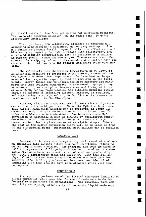
FACILITATED TRANSPORT OF n2z Facilita-ted transport of u S occcrs in liquid membranes consist-
ing of aqueous carbonate solutions according to the following process (refer to Figure 1) :
-.- 2
(1) H S dissolves in the membrane liquid at the high-pressure (2.p.) side of the film;
( 2 ) H2S decompose_s near the h.p. side of the film by the reaction H ~ S .+ nf + ns ;
efficiency of facilitated transport iembranes is that of Ward-and Robb ( 6 ) , who identified the use of an aqueous carbonate solution immobilized in '.
( 3 ) H+ produced in step ( 2 ) is consumed by CO= that is diffusing toward the h.p. side by the reaction H' f3CO; + nco; ;
( 4 ) HS- and HC03 diffuse from the h.p. to the low pressure (1.p.) side of the film;
66
mi .: R .I .I
+ ( 5 ) HS- combines with H near the 1.p. side of the film by the reaction HS i n+ + H ~ S ;
+ (6) H for step (5)& is supplied by HCO; by the reaction HCO; +
H' + CO5;
( 7 )
( 8 ) H 2 S produced in step (5) leaves the membrane.
Carbon dioxide also reacts with the membrane liquid as described
COT produced in step (6) diffuses back to the h.p. side;
by the overall reaction
4 ) C02 + CO; + H 2 0 + f 2HCO;
and,accordingly, it also experiences facilitated transport. How- ever, because the reaction rate of C02 with the membrane liquid is slow relative to that of H2S, alkaline absorbents demonstrate an in- herent selectivity for absorption of H2S in preference to CO . A means of improving this H2S/C02 selectivity still further will be described later.
In its present configuration, the immobilized liquid membrane for facilitated H2S transport consists of a concentrated (25-30 wt. % ) aqueous solution of K C03, although other membrane liquids including K PO4 solutions have geen screened. as a film a few thousandths of an inch thick by virtue of surface ten- sion forces in the pores of a hydrophilic polymeric support membrane.
The membrane liquid is immobilized
Two approaches have been pursued for maintaining the transmembrane H2S partial pressure gradient which drives membrane transport. first and simplest involves "sweeping" one face of the membrane with low pressure steam to dilute the acid gases which permeate across the membrane and keep their partial pressures low. The sweep steam carries the acid gases from the membrane permeator to a condenser, providing a dry mixture of H S and C 0 2 at a pressure sufficient for conversion of to elemental sulfur in a Claus plant or similar process. convenient to visualize the liquid membrane functioning as both the H2S absorption column and steam stripping column which are conventionally used for H 2 S removal. H2S absorption and solution regeneration occur within the membrane liquid film thickness rather than in two separate vessels operated at different pressures with absorbent pumped between them. A drawback to steam sweeping is that a high pressure difference corresponding to the difference between the gasification pressure and the sweep steam pressure must be supported across the liquid film. While the membrane support problem is significant, it is indeed feasible to operate liquid membranes under such conditions, and the steam sweeping approach is being pursued in a parallel program. How- ever, an alternative affords greater H2S membrane reliability.
membrane permeator by means of a pressurized liquid which is an H2S absorbent. This liquid sweep may simply be a concentrated solution of K2C03, identical in composition to the immobilized membrane liquid, which is isolated from the liquid membrane sandwich by a layer of non-wetted microporous polymer membrane which affords no significant resistance to H2S transport.
The
It is
The alternative involves sweeping permeated acid gases from the
Relatively little power is required to pressurize the sweep
67
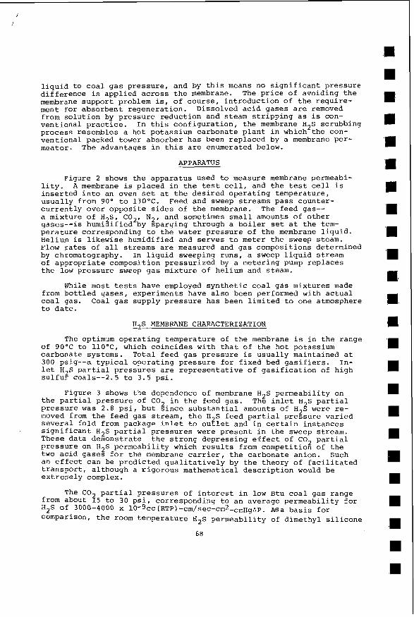
liquid to coal gas pressure, and by this means no significant pressure difference is applied across the membrane. The price of avoiding the membrane support problem is, of course, introduction of the require- ment for absorbent regeneration. Dissolved acid gases are removed from solution by pressure reduction and steam stripping as is con- ventional practice. process resembles a hot potassium carbonate plant in which the con- ventional packed tower absorber has been replaced by a membrane per- meator. The advantages in this are enumerated below.
In this configuration, the membrane H2S scrubbing
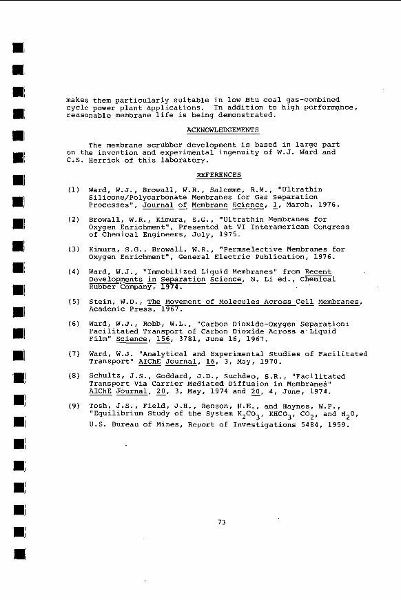
APPARATUS
Figure 2 shows the apparatus used to measure membrane permeabi- lity. A membrane is placed in the test cell, and the test cell is inserted into an oven set at the desired operating temperature, usually from 90' to 130OC. Feed and sweep streams pass counter- currently over opposite sides of the membrane. The feed gas-- a mixture of H S, C02, N , and sometimes small amounts of other gases--is humi3ified by gparging through a boiler set at the tem- perature corresponding to the water pressure of the membrane liquid. Helium is likewise humidified and serves to meter the sweep steam. Flow rates of all streams are measured and gas compositions determined by chromatography. In liquid sweeping runs, a sweep liquid stream of appropriate composition pressurized by a metering pump replaces the low pressure sweep gas mixture of helium and steam.
While most tests have employed synthetic coal gas mixtures made from bottled gases, experiments have also been performed with actual coal gas. Coal gas supply pressure has been limited to one atmosphere to date.
H2S MEMBRANE CHARACTERIZATION
The optimum operating temperature of the membrane is in the range of 90°C to llO°C, which coincides with that of the hot potassium carbonate systems. Total feed gas pressure is usually maintained at 300 psig--a typical operating pressure for fixed bed gasifiers. In- let H2S partial pressures are representative of gasification of high sulfur coals--2.5 to 3.5 psi.
Figure 3 shows the dependence of membrane H2S,permeability on the partial pressure of C02 in the feed gas. The inlet H S partial pressure was 2.8 psi, but since substantial amounts of H2Z were re- moved from the feed gas stream, the H S feed partial pressure varied several fold from package inlet to ou$l.. at an2 in certain instances significant H 2 S partial pressures were present in the sweep stream. These data demonstrate the strong depressing effect of C02 partial pressure on H2S permeability which results from competition of the two acid gases for the membrane carrier, the carbonate anion. Such an effect can be predicted qualitatively by the theory of facilitated transport, although a rigorous mathematical description would be extremely complex.
from about 2 5 to 30 psi, corresponding to an average permeability for H2S of 3000-4000 x 10-9cc(RTP)-cm/sec-cm2-cmHgAP. ASa basis for comparison, the room temperature H2S permeability of dimethyl silicone
68
The CO partial pressures of interest in low Btu coal gas range
rn
m
m rn R
Rl R m R
m
rubber, the most permeable polymeric membrane available, is 850 x lo-'. Unlike silicone rubber, the immobilized liquid membrane is virtually perfectly selective for acid gases; other coal gas components cross the membrane by the so1ution;diffusion mechanism, and solubilities in the hot, very concentrated salt solution are quite low.
H 2 S permeability is essentially unchanged upon raising the operating temperature from 90 to llO"C, although an increase in C 0 2 permeability results in a decreased selectivity for H 2 S over C 0 2 at the higher temperature. H 2 S permeability is also relatively in- sensitive to carbonate solution concentration,apparently due to competing effects between higher carrier loading and decreased dif- fusivities and activity coefficients at the high concentrations employed.
The permeation coefficient for H 2 S also depends on its own partial pressure in addition to that of C02; in Figure 4 , the feed gas C02 partial pressure has been fixed while H S inlet concentration is varied. limited to 15-30%, accurate point values of H S permeability were obtained. membrane carrier mechanism is saturated--that is, the extent of the facilitation is limited by the availability of the carbonate carrier for reaction at the feed side of the membrane, and H S permeability falls off sharply at high partial pressures. below about 3 psi, the permeation coefficient increases modestly with decreasing reactant partial pressure. This saturation phenomenon is a general feature of facilitated transport systems. The performance of facilitated transport membranes is made more difficult to describe due to the dependence of permeation coefficient on permeant partial pressure. This contrasts with the relatively simple situation for polymeric membranes in which permeability is often a constant charac- teristic of the identity of the permeating gas but not its pressure.
Since the extent of H 2 S remova? from the feed gas was
At high feed partial pressures of Zydrogen sulfide, the
For H 2 Z partial pressures
Membrane permeability to H 2 S depends on sweep side acid gas partial pressures as well as on those in the feed gas. In the liquid sweep runs summarized in Figure 4 , the extent of conversion of in- coming carbonate sweep solution to the bicarbonate form was varied to simulate different degrees of absorbent regeneration in the steam stripping process. The calculated equilibrium C 0 2 partial pressures exerted by the incompletely regenerated sweep liquid are shown in Figure 4 . The two dashed lines indicate that H 2 S transport is further hindered by the presence of the competing permeant Co2 on the sweep side of the membrane.
flux in two ways--(l) 1?y decreasing the H 2 S partial pressure difference across the membrane (i.e., the driving force for transport) and ( 2 ) by decreasing the facilitation factor due to the decreased concentration gradient in bisulfide and bicarbonate ions resulting from partial membrane liquid conversion by H2S in the sweep stream.
As observed earlier, the transport of carbon dioxide is also facilitated by the carbonate membrane system. An important difference between H 2 S and C 0 2 facilitated transport is that, while the chemical reactions which augment H S flux are sufficiently rapid that H ~ S transport is essentially $if fusion rate limited, the reaction of
The presence of H S in the sweep stream influences transmembrane
69
Co2 with the membrane liquid is relatively slow due to the sluggish kinetics of C02 hydrolysis. are important in determining the permeation rate of C02. of the difference in reaction rates is that carbonate absorbents-- whether immobilized as liquid membranes or not--exhibit an apparent selectivity for absorption of H S in preference to C02,and membrane C 0 2 permeability is much lower ghan that of H2S.
the gas-liquid interface permits him to further improve this inherent selectivity for absorption of H2S over C02. selectivity can be enhanced by splitting a given total membrane liquid film thickness into two or more liquid layers, each separated by a thin gas-filled space. This so-called "gas gap" is conveniently pro- vided by a layer of a suitable non-wetting microporous polymer mem- brane. The rate of H2S transport, being diffusion-limited, depends only on the total thickness of the membrane liquid films acting as diffusion barriers. Since the mass transfer resistance to H2S of the intervening gas gap is entirely negligible, the H2S permeability is not effected by this arrangement of the membrane sandwich. In contrast, the transport rate of C02 is diminished by dividing the mem- brane liquid film into multiple layers, since the C02 flux is sensi- tive to the rate of the relatively slow chemical reaction between C 0 2 and membrane liquid and since these slow reactions are forced to occur an additional time for each new gas-liquid interface which is created. According to this much oversimplified description, the C 0 2 transport rate is approximately halved by a single gas gap, de- creased 3-fold with two gas gap interlayers, =., with a correspond- ing increase in H2S:C0 separation factor a at no cost in reduced H2S permeability. It should be observed that the selectivity enhancement requires only that the C 0 2 reaction be slow relative to that of H2S, since competition between these two reactants for membrane carrier determines selectivity. The C02 absorption reaction might be fast compared to the diffusion process.
Figure 6 shows that this simple analysis describes experimental data quite adequately. The ratio of H 2 S and C02 fluxes has been determined for three membrane sandwich configurations and plotted as a function of C02 partial pressure in the feed stream: inlet H2S concentration was fixed. selectivity as predicted by theory, as the spacing and slopes of $he lines drawn through the three data sets indicate. With a double gas gap arrangement (three membrane liquid layers) and a synthetic coal
ratio is increased from about 0.5 (no gas gap? to 1.5, corresponding to a permeate composition enrichment from 33% to 60% H ~ S in co2. Selectivity for H2S absorption is particularly important for integrated combined cycle power generation from low Btu coal gas for reasons discussed below.
Permeation data such as the above are used in predicting the
Hence, reaction rates as well as equilibria The significance
The high degree of control which the membrane designer has over
Figure 5 shows how HZS:C02
Multilayering is seen to improve H2S:C0
gas f e d COi?tainiiig 2.7 psi E S d i d 2 0 psi CO , the H2S:C02 flux 2
membrane area requirement for any given application. permeability of facilitated transport membranes depends on reaction kinetics and equilibria, it is not possible to characterize membrane performance by a simple permeability "constant" as for polymeric mem- branes, and in fact the permeation constant varies significantly from permeator inlet to outlet in the following integration:
70
Since the
E
6 E
Im
E
R
P II 'a B E I
R
'M I
111 m;
I;
RI
I;
Dl Ri
Dl
BI II
0
where Ft and Pt are the volumetric flowrate and total pressure of the Coal gas feed. brane is calculated b$ material balance. involving desulfurization 05 low-Btu coal gas produced from high sul- fur coal, a range of 1-2 ft capacity is predicted.
The H S partial pressure difference across the mem- For typical applications
of membrane area per kilowatt of generating
MEMBRANE H2S SCRUBBING OF LOW BTU GAS
The conceptual layout of a liquid swept membrane H2S scrub- bing system is shown in Figure 7; it is very similar to the hot carbonate flowsheet with the exception of the replacement of the conventional absorber with the novel membrane permeator.
cycle power plant are due to the controllable, high membrane selecti- vity for H s absorption. gas mass flow to the gas turbine, decreases the turbine compressor air requirement, and thus increases the net shaft work delivered to the gas turbine generator. On the other hand, passage of large amounts of CO is to be avoi2ed for a number of reasons.
Many of the benefits of membrane H S scrubbing in the combined
Minimizing C02 removal increases the fuel
through the H2S removal and sulfur conversion trains
The total amount of acid gas flowing through the sulfur re- moval and conversion trains is less, of course, for the more selective process; specifically, three times less acid gas must be processed on a molar basis if the product stream from the H2S stripper consists of 60% H2S in C02 rather than 20% H S. A de- crease in the total amount of absorbed acid gases to ge stripped from solution should reduce the stripping steam requirement. Since insufficient waste heat is available in the plant to raise all the low pressure stripping steam required, a portion must be extracted from the steam turbine at a penalty in reduced power output; this penalty is minimized by high membrane selectivity. In short, less gasification, heat recovery, and gas and steam tur- bine equipment need be purchased per megawatt of exported power when selective membrane scrubbing is employed, and power plant first costs are thus reduced by more effective use of the energy available in the coal gas. The net plant heat rate is also im- proved by routing C02 to the turbines, reflecting lower operat- ing as well as first costs.
A final consideration as regards the power plant is that a number of H S removal processes, including the membrane scrubber, employ concengrated solutions of alkali metal salts as absorbents. With conventional absorption columns, a possibility exists for alkali metal carryover due to entrainment or foaming. This is unacceptable in view of the extremely low gas turbine tolerance
71
for alkali metals in the fuel gas due to hot corrosion problems. The carbonate membrane solution, on the other hand, is quite effectively immobilized.
The high absorption selectivity afforded by membrane H S scrubbing also results in equipment and utility savings in ghe H2S scrubbing process itself. bent carrying capacity for H S increases with selectivity, and a reduced solution recirculazion rate is possible at a savings in pumping power. Since gas and liquor flowrates are down, the size of the stripping column is decreased, and a smaller acid gas condenser duty follows from the reduced stripping steam consump- tion.
Specifically, the effective absor-
The relatively high absorption temperature of 90-110"C is an advantage relative to processes which operate nearer ambient. The higher the absorption temperature, the less heat exchange area and heat rejection capacity that is required in the fuels plant. mized and less polluted condensate is generated. By operating at somewhat higher absorption temperatures and living with in- creased K2C03 makeup requirements, the alkaline membrane liquid should be capable of absorbing carbonyl sulfide, if required, and hydrolyzing it to H S and C 0 2 to facilitate its conversion to elemental sulfur in $he Claus plant.
Energy losses due to incomplete heat recovery are mini-
Finally, Claus plant capital cost is sensitive to H2S con- centration in the acid gas feed. sive partial combustion process may be employed; at lower H2S concentrations, the split-stream configuration is required in order to achieve stable combustion. Furthermore, since H 2 S conversion to elemental sulfur is limited by equilibrium consi- derations, sulfur conversion efficiency increases with H2S concentration for a given number of catalytic stages. Since the cost of the sulfur conversion plant will be as large as that of the H2S removal plant, substantial cost savings can be realized here.
Above 50% H a s , the less expen-
MEMBRANE L I F E
Because of the very severe operating environment of coal gas, an extensive life testing effort has been undertaken, focussing on the liquid swept membrane. The membrane has been operated at 9 0 ° C and a pressure ~f 300 psig with synthetic coal gas mixtures. Tests have also been performed on actual coal gas produced by the GEGAS-F atmospheric fixed bed gasifier. Both chemical and physical effects have been sought and solutions developed for membrane life-limiting problems as they have been identified. Promising life test results have been obtained which will soon be reported.
CONCLUSIONS
The superior performance of facilitated transport immobilized liquid membranes makes possible the use of membranes to do in- dustrially significant gas separations. meability and H2S:C02 selectivity of carbonate liquid membranes
The extremely high per-
72
makes them particularly suitable in low Btu coal gas-combined cycle power plant applications. In addition to high performance, reasonable membrane life is being demonstrated.
ACKNOWLEDGEMENTS
The membrane scrubber development is based in large part on the invention and experimental ingenuity of W.J. Ward and
Herrick of this laboratory.
REFERENCES
Ward, W.J., Browall, W.R., Salemme, R.M., “Ultrathin Silicone/Polycarbonate Membranes for Gas Separation Processes”, Journal of Membrane Science, 1, March, 1976. Browall, W.R., Kimura, S.G., “Ultrathin Membranes for Oxygen Enrichment“, Presented at VI Interamerican Congress of Chemical Engineers, July, 1975.
Kimura, S.G., Browall, W.R., “Permselective Membranes for Oxygen Enrichment“, General Electric Publication, 1976.
Ward, W.J., “Immobilized Liquid Membranes“ from Recent Developments & Separation Science, N. Li ed., Chemical Rubber Company, 1 9 7 4 .
Stein, W.D., The Movement of Molecules Across C g Academic Press, 1967.
Membranes,
Ward, W.J., Robb, W . L . , “Carbon Dioxide-Oxygen Separation: Facilitated Transport of Carbon Dioxide Across a Liquid Film” Science, 156, 3781, June 16, 1967. Ward, W.J. “Analytical and Experimental Studies of Facilitated Transport“ AIChE Journal, 16, 3, May, 1970. Schultz, J.S., Goddard, J.D., Suchdeo, S.R., “Facilitated Transport Via Carrier Mediated Diffusion in Membranes” AIChE Journal. 20, 3 , May, 1974 and 20, 4, June, 1974. Tosh, J.S., Field, J.H., Benson, H . E . , and Haynes, W.P., “Equilibrium Study of the System K2C03, KHC03, COz, and H 2 0 , U .S . Bureau of Mines, Report of Investigations 5484, 1959.
73
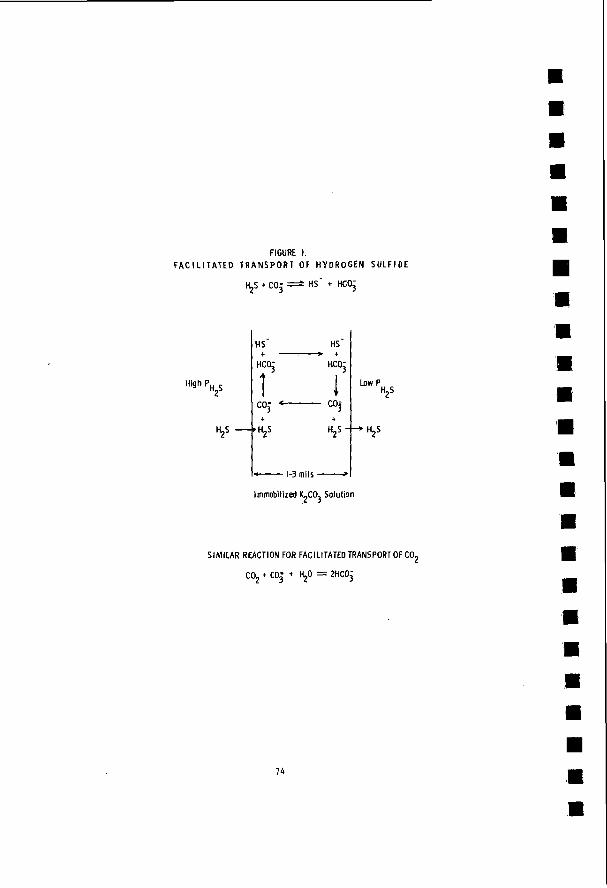
FIGURE 1. F A C I L I T A T E D T R A N S P O R T OF H Y D R O G E N S U L F I D E
coj t
I- 1-3 mils -1 Immobilized %GO3 Solution
SIMILAR REACTION FOR FACl LITATED TRANSPORT OF C02
co + co- + 50 = PHCOi 2 3
74
E
E E R E E
m c R E
I E I Is m I 1 ,m
e m
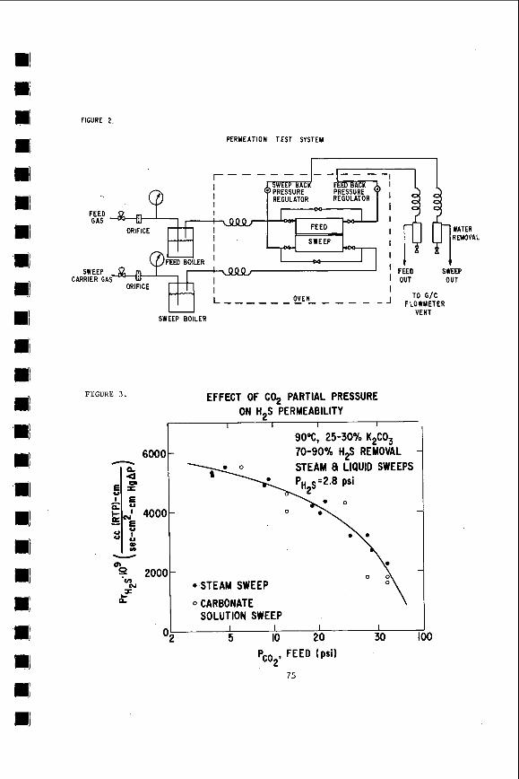
FIGURE 2 .
6000 - a. Q,
6 5 - 5 % &
0 2000- 'v)
l i
E l 0
4000
a u) -
b)
(u I
O2
PERMEATION TEST SYSTEM
I I I I
90%, 25-30% K2C03 - 70-90°/o H$ REMOVAL
STEAM 8 LIQUID SWEEPS
-
*STEAM SWEEP
0 CARBONATE SOLUTION SWEEP
I I I I 5 IO 20 30 100
FEED GAS
SWEEP CARRIER GA
FLOWMETER VENT
SWEEP BOILER
FIGURE 3 .
O\
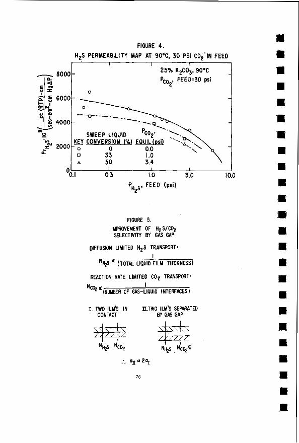
FIGURE 4. H2S PERMEABILITY MAP AT 90°C, 30 PSI C02-IN FEED
I I I 25% K2C03, 90°C - 8000- - Pco2, FEED.30 psi
-
---IT---- -
-
I I I
OO. I 0.3 I .o 3.0 10.0
PH2s, FEED (psi)
FIGURE 5. IMPROVEMENT OF H2 S/CO2 SELECTIVITY BY GAS GAP
DIFFUSION LIMITED H2S TRANSPORT: I
a (TOTAL LIQUID FILM THICKNESS)
REACTION RATE LIMITED C02 TRANSPORT: I
Nq ‘(NUMBER OF as-LtautD INTERFACES)
I. TWO ILM’S IN II.TWO ILM’S SEPARATED CONTACT BY GAS GAP
76
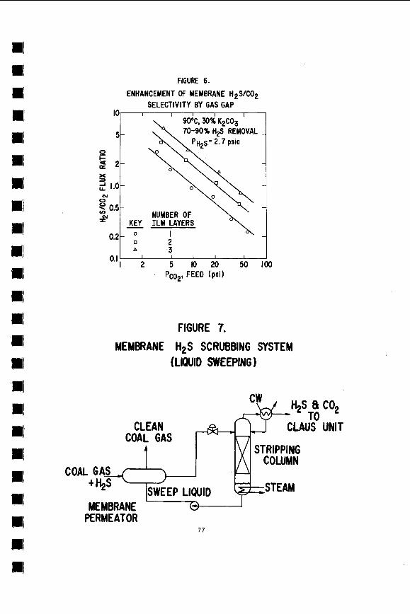
FIGURE 6. ENHANCEMENT OF MEMBRANE HzS/C02
SELECTIVITY BY GAS GAP IO I I I I I
5-
90°C, 30% K2CO3 70-90% ti$ REMOVAL -
P H ~ s = 2.7 psia 0
X =I 2 1.0- hl 0
0.5 NUMBER OF - KEY I L M LAYERS #?
-
A 3 I I I I I
1 2 5 IO 20 50 100 Pco2, FEED (psi)
0. I
I 0.21 2
O
FIGURE 7. MEMBRANE H2S SCRUBBING SYSTEM
(LIQUID SWEEPING 1
PERMEATOR 77
Hot Low-Btu G a s P u r i f i c a t i o n w i t h C o a l A s h , 0. J. Hahn a n d M. R . H e i l i g , Insti- tute f o r Mining and M i n e r a l s R e s e a r c h , U n i v e r s i t y of Kentucky, Lexington , KY
:R 40506.
An er.perirr.enta1. s t u d y was c a r r i e d out to P v a l u S e t h e r e m o v a l 0: 9,s and O t h e r s u l f u r c o m p o u n d s f r o m hot low Btu p r o d u c e r g a s usirg g a s i f i e r a s h . p h a s i z e d t h e r m o g r a v i m e t r i c s t u d i e s of t h e b a s i c a b s o r p t i o n snd r e g e n e r a t i o n cf a s n a s a func t ion of t e m p e r a t u r e , p a r t i c l e g a s size c o m p o s i t i o n and r e s i d e n c e t i m e . T n e g a s c o m p o s i t i o n s t u d i e d include (t+,,S, N.J, (H,S, H,, N2), (HzS, H,, CO, Na), (S::S, CH,,
a t u r e r a n g e v a r i e d From EO0 t o 1600oF. i s p r e c e d e d by t h e reduct ion of t h e i r o n to t h e e l e m e n t a l f o r m .
of H,.
T h e p r e s e n t work em- E
H ~ , co, q, (H,s, ci+4p, H,, Co, co,, N,) a n d (H,s, COS, *:2 , CO, N~). ~ i ; e t e m p e r - T h e a b s o r p t i o n OF H I S i n t h e i r o n o x i d e m a t r i x
:m In t h e case of ( H , S , N2) g a s t h e a b s o r p t i o n w a s r e s t r i c t e d by t h e f o r m a t i o n r a t e
78
HOT GAS CLEANUP PROCESS FOR REMOVING H.S FROM LOW-BTU GASES USING IRON OXIDE ABSORBENTS
E . C . Oldaker and D. W . Gillmore
Energy Research and Development Administration Morgantown Energy Research Center
Morgantown, West Vi rg in ia
INTRODUCTION
Research i s cont inuing a t t h e Morgantown (West Vi rg in ia ) Energy Research Center, Energy Research and Development Administration, t o develop a hot gas cleanup process using s o l i d regenerable sorbents t o remove hydrogen s u l f i d e from hot (1000°-15000F) low-Btu fuel gas made from coal . A s u i t a b l e process i s needed whereby s u l f u r can be removed from low-Btu gases so t h a t high s u l f u r c o a l s can be u t i l i z e d t o provide c lean energy and meet t h e environmental s tandards regula t ing t h e amount of s u l f u r re leased t o t h e atmosphere. Removal o f hydrogen s u l f i d e without cool ing t h e gas would con- serve t h e heat l o s t in conventional gas p u r i f i c a t i o n methods, t h u s increas ing t h e thermal e f f ic iency by 15 percent .
The use o f i ron oxide t o remove H2S from i n d u s t r i a l gases has been prac t iced f o r many years . Indeed, research by t h e Appleby-Frodingham S t e e l Company during t h e l a t e f i f t i e s led t o t h e cons t ruc t ion and operat ion o f a p l a n t desu l fur iz ing about 2% mi l l ion cubic f e e t o f coke oven gas per day followed by cons t ruc t ion o f a 32 mi l l ion cubic f e e t per day plant before opera t iona l problems and economic c o s t s shut down t h e opera t ions . The crude coke oven gas was passed through a f lu id ized-bed o f s i n t e r e d i ron oxide powder (-16 mesh + 100 mesh) where reac t ion with HzS and FeaOn took p lace a t tempera- t u r e s approaching 40OoC. 95-98 percent o f t h e HzS from t h e coke oven gas . The p r i n c i p a l problems encountered, a s f a r as t h e use of i ron oxide was concerned, were massive a t t r i t i o n and replacement of t h e f i n e s , plugging and erosion of pipes t r a n s p o r t i n g t h e i ron oxide. These d i f f i c u l t i e s encountered by t h e Appleby-Frodingham process have been overcome by placing t h e i ron oxide p a r t i c l e s on a support ing matr ix composed o f f l y ash, o r s i l i c a , by thoroughly mixing t h e two components, extruding t h e pas te - l ike mixture i n t o 1/4-inch diameter by 3/4-inch long cy l inders and s i n t e r i n g a t 1800OF.
This process , as repor ted by Reeves et a1 (i), removed
The chemistry involved i n absorpt ion and regenera t ion us ing i r o n oxide shows t h a t i ron s u l f i d e s a r e produced when H2S r e a c t s with Fe,O3 with t h e empir ical com- pos i t ion approaching FeS1.5
Fezon + 3H2S e. 2FeSl., + 3Hz0
However, according t o Imperial Chemical I n d u s t r i e s Cata lys t Handbook (2) , f r e s h i r o n oxide is converted t o FesOu i n t h e presence o f hydrogen and a t temperatures above 650°F. Therefore, t h e reac t ion would be w r i t t e n a s
Fes04 + 4H2S 2FeS + FeS2 + 4Hz0
During regenerat ion, a i r ox id izes t h e FeS and FeS2 t o Fe30u and SOz:
However, in t h e presence of excess oxygen, t h e Fes04 is converted t o FezOs. condi t ion e x i s t s , then upon t h e s t a r t o f another absorpt ion cyc le , some hydrogen i s consumed from t h e raw producer gas while conversion t o Fes04 i s tak ing p lace
I f t h i s
79
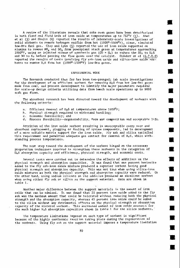
A review of t h e l i t e r a t u r e revea ls t h a t coke oven gases have been desulfur ized in both f ixed and f l u i d beds of i ron oxide a t temperatures up t o 752'F (1). e t a1 (3) and Shul tz (5) reported t h e r e s u l t s of labora tory-sca le investTgat ions of s o l i d sorbents t o remove hydrogen s u l f i d e from hot (1000~-1500°F), c lean , simulated low-Btu f u e l gas. alumina t o remove NOx and SOx f r o m powerplant s tack gases a t temperatures approaching 1000°F, using an in jec ted stream of synthes is gas (CO + H a ) t o reduce t h e SOr t o H z S and NO t o N2 before passing t h e f l u e gases over t h e c a t a l y s t . reported t h e r e s u l t s of t e s t s involving f l y ash- i ron oxide and s i l i c a - i r o n oxide sor - bents t o remove HzS from hot (1000°-15000F) low-Btu gases .
Abel
Clay and Lynn (5) repor ted t h e u s e of i ron oxide supported on
Oldaker e t a1 (6,1,8-,2)
EXPERIMENTAL WORK
The Research conducted t h u s far has been two-pronged; lab s c a l e inves t iga t ions f o r t h e development o f an e f f i c i e n t sorbent f o r removing H z S from hot low-Btu gases made from coal , and process development t o i d e n t i f y t h e major parameters required f o r scale-up design c r i t e r i a u t i l i z i n g d a t a from bench s c a l e operat ions up t o 9000 scfh gas flows.
The absorbent research has been d i r e c t e d toward t h e development of sorbents with t h e following c r i t e r i a :
a . b. Physical s t rength requi red t o withstand handl ing; c. Economic f e a s i b i l i t y ; and d. Process feasibility--regenerability, form and composition and acceptable l i f e .
A t t r i t i o n of t h e i ron oxide sorbent r e s u l t i n g i n unacceptable c a r r y over and
E f f i c i e n t removal o f HzS a t temperatures above 1000°F;
absorbent replacement, plugging or foul ing of system components, l ed t o development o f a more s u i t a b l e matrix support f o r t h e i r o n oxide. Fly ash and s i l i c a s a t i s f i e d t h i s requirement and permit ted adequate gas contact f o r removal of H 2 S , while with- s tanding process temperatures.
The next s t e p toward t h e development o f t h e sorbent hinged on t h e necessary preparat ion techniques required t o s t rengthen t h e s e sorbents in t h e ca tegor ies of H2S absorpt ion capac i ty and e f f i c i e n c y , phys ica l s t rength , and economic cos ts .
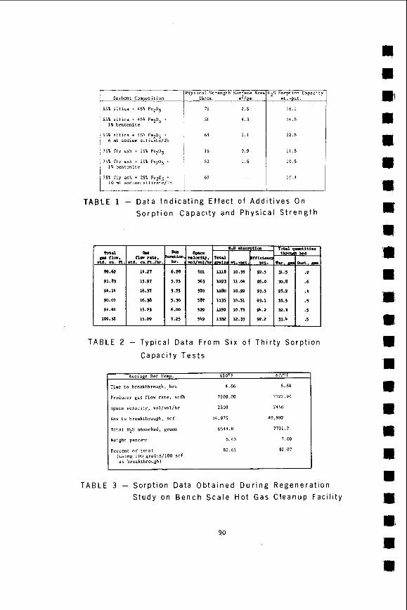
Several t e s t s were c a r r i e d out t o determine t h e e f f e c t s of addi t ives on t h e physical s t rength and absorpt ion c a p a c i t i e s . added t o t h e f l y ash-iron oxide mixture produced a super ior sorbent having good physical s t rength and absorpt ion capac i ty . oxide mixtures a s both t h e physical s t r e n g t h and absorpt ion capaci ty were reduced. t h e o ther hand, us ing sodium s i l i c a t e as t h e a d d i t i v e produced an exce l len t sorbent when using e i t h e r f l y ash o r s i l i c a a s t h e support mater ia l . t a b l e 1.
I t was found t h a t one percent bentoni te
This was not t r u e when using s i l i c a - i r o n On
Data a r e shown i n
Another major d i f fe rence between t h e support mater ia l s is t h e amount of i ron oxide t h a t can be admixed. ash was t h e maximum amount t h a t could be t o l e r a t e d without reducing both t h e physical s t r e n g t h and t h e absorpt ion capac i ty , whereas 45 percent i ron oxide could be added t o t h e s i l i c a without any detr imental e f f e c t s on t h e physical s t r e n g t h o r absorpt ion capac i ty o f t h e s i n t e r e d sorbent . t h e much higher H 2 S absorpt ion c a p a c i t i e s shown in t a b l e 1 f o r t h e s i l i c a sorbents . '
The temperature l i m i t a t i o n s imposed on each type of sorbent i s s i g n i f i c a n t
It was found t h a t 25 percent i r o n oxide added t o t h e f l y
This increased amount of i ron oxide accounts f o r
because of t h e highly exothermic reac t ion t a k i n g place during t h e regenerat ion of t h e sorbents . Using f l y ash a s t h e support mater ia l imposes a temperature l i m i t a t i o n
80
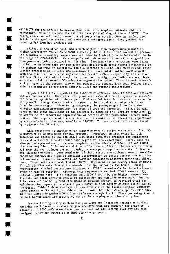
Of 1500°F f o r i h e sorbent t o have a good l e v e l of absorp t ion capac i ty and l i f e expectancy. fusing c h a r a c t e r i s t i c would cause l o s s o f pores t h u s c u t t i n g down on sur face a rea a v a i l a b l e f o r good gas contac t and eventua l ly rendering t h e sorbent use less f o r removing HIS from hot producer gas.
This i s because f l y ash a c t s a s a g lass - fus ing a t around 1500'F. The
S i l i c a , on t h e o ther hand, has a much higher fusion temperature permit t ing higher temperature operat ion without a f f e c t i n g t h e a b i l i t y of t h e sorbent t o perform. The recommended opera t ing temperature ind ica ted by l i m i t e d d a t a i s bel ieved t o be i n t h e range of 17000-18000F. t i o n processes being developed a t t h i s time. c a r r i e d out on o t h e r than low-Btu gases does not conta in c o n s t i t u e n t s detr imental t o t h e sorbent mater ia l o r reac t ions , t h e two sorbents could be used on most coa l g a s i f - i c a t i o n processes e f f i c i e n t l y and economically. from t h e gas i f ica t ion process may cause detr imental e f f e c t s especial ly . i f t h e f ixed bed concept is u t i l i z e d , although t h e l a b s c a l e i n v e s t i g a t i o n s i n d i c a t e t h e carbon- aceous mater ia l i s burned o f f during t h e regenerat ion cyc le . work going on a t t h e present t ime on hot p a r t i c u l a t e removal from coal-der ived gases , which i s e s s e n t i a l t o pro jec ted combined cyc le and t u r b i n e a p p l i c a t i o n s .
This range i s well above most i f not a l l coal g a s i f i c a - Provided t h a t t h e present work being
P a r t i c u l a t e mat te r c a r r i e d over
There i s much research
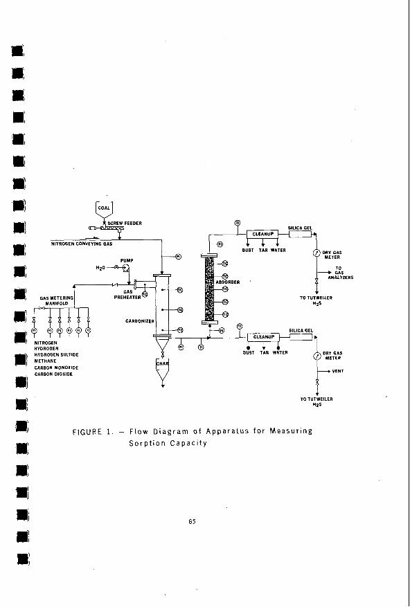
Figure 1 is a flow diagram o f t h e laboratory apparatus used t o t e s t and eva lua te Generally, t h e gases were metered i n t o t h e system t o s imula te
Coal was fed i n t o t h e system a t r a t e s up t o t h e var ious sorbents . t h e a c t u a l composition o f producer gas. 500 grams/hr through t h e carbonizer t o provide t h e a c t u a l t a r s and p a r t i c u l a t e s found i n producer gas . absorber containing approximately 700 grams o f prepared sorbents . The H 2 S is moni- to red at t h e input and output of t h e absorber by means o f t h e Tutwiler technique (E) t o determine t h e absorpt ion capac i ty and e f f i c i e n c y of t h e p a r t i c u l a r sorbent being t e s t e d . by means of e l e c t r i c h e a t e r s , usua l ly a t 1100OF. The gas output i s a l s o monitored by analyzers f o r CO and H2.
Af te r being preheated, t h e producer gas flows i n t o t h e
The temperature of t h e absorbent bed i s maintained a t opera t ing temperature
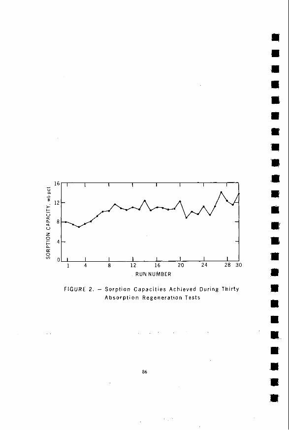
Li fe expectancy i s another major parameter used t o eva lua te t h e worth o f a h igh temperature s o l i d absorbent f o r HzS removal. Therefore, an i r o n oxide-f ly ash absorbent was t e s t e d on t h e l a b s c a l e u n i t using s imulated producer gas containing t a r s and p a r t i c u l a t e s t o determine some degree of l i f e expectancy. Thi r ty complete absorpt ion-regenerat ion cyc les were completed on t h e same absorbent . I t was found t h a t t h e recycl ing o f t h e sorbent d i d not a f f e c t t h e a b i l i t y o f t h e sorbent t o remove HzS from t h e hot producer gas maintaining an average absorpt ion capac i ty o f 10 w t . - pct . during t h e t e s t s . condi t ion without any s igns o f physical d e t e r i o r a t i o n o r caking between t h e ind iv id- ual sorbents . Figure 2 i n d i c a t e s t h e sorp t ion c a p a c i t i e s achieved during t h e t h i r t y runs. These t e s t s were conducted a t 110O0F. Regeneration was accomplished by u s i n g 12 scfh a i r flow r a t e through t h e absorber f o r approximately two hours . regenerat ion, t h e bed temperature increased t o 1700°F momentarily i n t h e a c t u a l wave f ront o r zone o f reac t ion . without apparent harm, it is bel ieved t h a t 15000F would be t h e highest temperature f l y ash-iron oxide sorbents should be exposed f o r optimum l i f e expectancy. l i f e t e s t s a r e now being conducted where an optimum sorbent i s recycled u n t i l t h e H2S absorption capac i ty decreases s i g n i f i c a n t l y so t h a t b e t t e r def ined l i m i t s can be predicted. t e s t s using t h e f l y ash- i ron oxide sorbent . Note t h a t t h e H 2 S absorpt ion e f f i c i e n c y is given using 400 grains/100 s c f a s t h e break through l i m i t . be much higher using 150 grains/100 scf a s t h e s topping point f o r absorpt ion.
Upon completion o f t h e s e t e s t s , t h e sorbents were i n excel lent
During
Although t h i s temperature reached 17000F momentarily,
Further
Table 2 shows t h e t y p i c a l da ta from s i x of t h e t h i r t y sorpt ion capac i ty
These percentages would
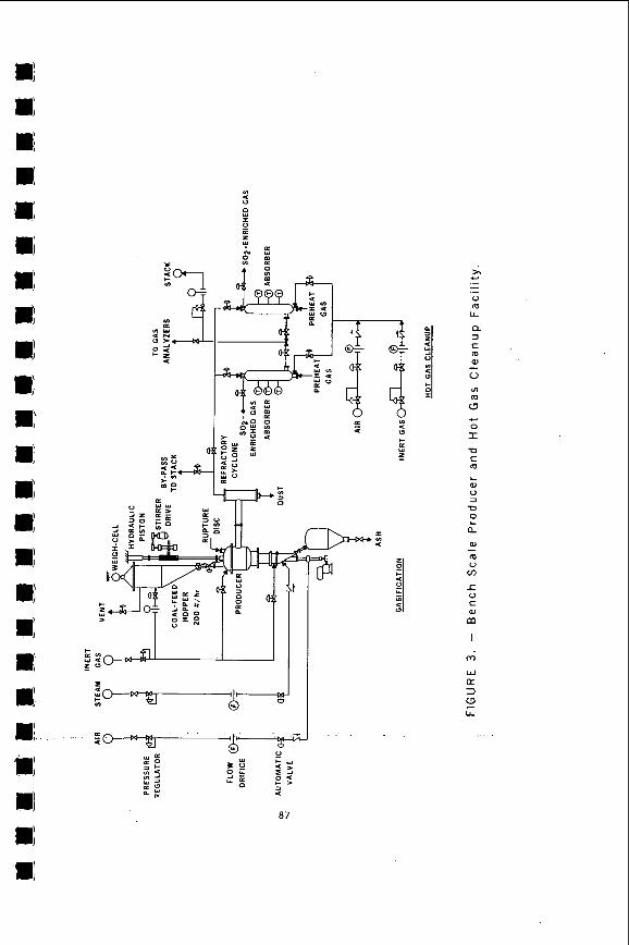
Further t e s t i n g , using much higher gas flows and increased amounts of sorbent mater ia l was bel ieved necessary t o generate da ta t h a t a r e requi red f o r scale-up c r i t e r i a . designed, b u i l t and i n s t a l l e d a t MERC f o r t h i s purpose.
A 9000 s c f h atmospheric producer and hot gas cleanup f a c i l i t y has been
8 1
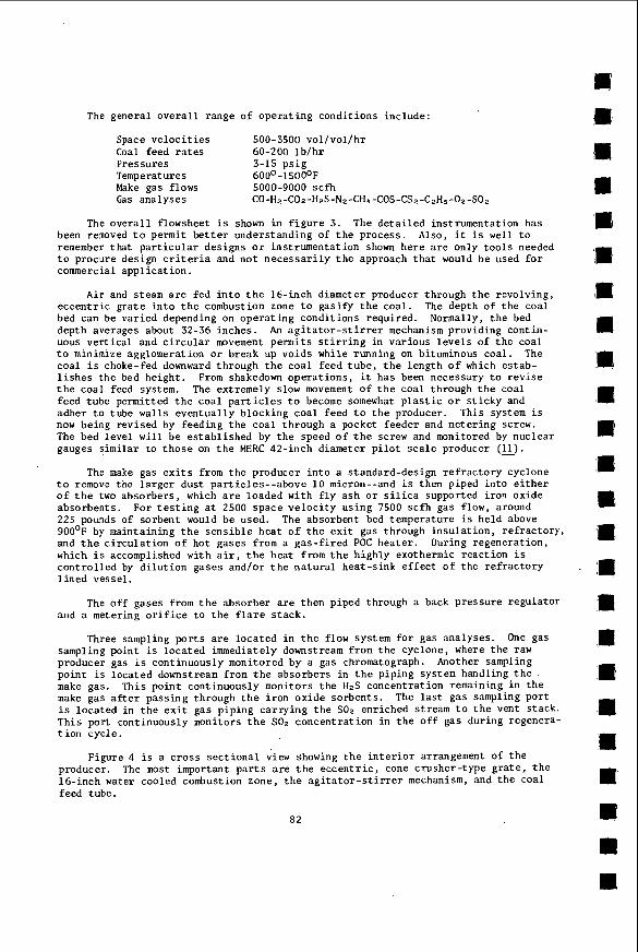
The general o v e r a l l range of opera t ing condi t ions include:
Space v e l o c i t i e s 500-3500 vol /vol /hr Coal feed r a t e s 60-200 I b / h r Pressures 3-15 p s i g Temperatures 600'-1 500°F Make gas flows 5000-9000 s c f h Gas analyses CO-H~-COz-H~S-N~-CH~-COS-CSz-CzH~-Oz-SOz
The o v e r a l l flowsheet is shown i n f i g u r e 3. The d e t a i l e d instrumentat ion has been removed t o permit b e t t e r understanding of t h e process . Also, it is well t o remember t h a t p a r t i c u l a r designs o r instrumentat ion shown here a r e only t o o l s needed t o procure design c r i t e r i a and n o t n e c e s s a r i l y t h e approach t h a t would be used f o r commercial appl ica t ion .
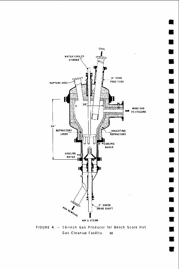
A i r and steam are fed i n t o t h e 16-inch diameter producer through t h e revolving, eccent r ic g r a t e i n t o t h e combustion zone t o gas i fy t h e coa l . The depth of t h e coal bed can be var ied depending on opera t ing condi t ions required. depth averages about 32-36 inches. An a g i t a t o r - s t i r r e r mechanism providing cont in- uous v e r t i c a l and c i r c u l a r movement permits s t i r r i n g i n var ious l e v e l s of t h e coal t o minimize agglomeration o r break up voids while running on bituminous coa l . The coal i s choke-fed downward through t h e c o a l feed t u b e , t h e length o f which es tab- l i s h e s t h e bed height . From shakedown opera t ions , it has been necessary t o r e v i s e t h e coal feed system. The extremely slow movement o f t h e coa l through t h e coal feed tube permitted t h e coa l p a r t i c l e s t o become somewhat p l a s t i c o r s t i c k y and adher t o tube wal l s eventua l ly blocking c o a l feed t o t h e producer. now being revised by feeding t h e c o a l through a pocket feeder and metering screw. The bed leve l w i l l be es tab l i shed by t h e speed o f t h e screw and monitored by nuc lear gauges s imi la r t o t h o s e on t h e MERC 42-inch diameter p i l o t s c a l e producer (E).
Normally, t h e bed
This system i s
The make gas e x i t s from t h e producer i n t o a standard-design r e f r a c t o r y cyclone t o remove the l a r g e r dust par t ic les - -above 10 micron--and is then piped i n t o e i t h e r o f t h e two absorbers , which a r e loaded with f l y ash o r s i l i c a supported i ron oxide absorbents . 225 pounds of sorbent would be used. 900°F by maintaining t h e s e n s i b l e hea t o f t h e e x i t gas through i n s u l a t i o n , re f rac tory , and t h e c i r c u l a t i o n o f ho t gases from a gas- f i red POC hea ter . During regenerat ion, which i s accomplished with a i r , t h e hea t from t h e h ighly exothermic reac t ion i s c o n t r o l l e d by d i l u t i o n gases and/or t h e n a t u r a l heat-s ink e f f e c t o f t h e r e f r a c t o r y l i n e d vessel .
For t e s t i n g at 2500 space v e l o c i t y using 7500 s c f h gas flow, around The absorbent bed temperature i s he ld above
The o f f gases from t h e absorber a r e then piped through a back pressure regula tor and a metering o r i f i c e t o t h e f l a r e s t a c k .
Three sampling p o r t s a r e loca ted i n t h e flow system f o r gas analyses . One gas sampling poin t i s loca ted immediately downstream from t h e cyclone, where t h e raw producer gas is cont inuously monitored by a gas chromatograph. Another sampling poin t i s loca ted downstream from t h e absorbers in t h e p ip ing system handling t h e . make gas. make gas a f t e r passing through t h e i ron oxide sorbents . i s loca ted in t h e e x i t gas p ip ing car ry ing t h e SOa enriched stream t o t h e vent s tack . This port cont inuously monitors t h e SOz concent ra t ion i n t h e o f f gas during regenera- t i o n cyc le .
This poin t cont inuously monitors t h e H.S concentrat ion remaining i n t h e The l a s t gas sampling por t
Figure 4 i s a c r o s s s e c t i o n a l view showing t h e i n t e r i o r arrangement of t h e producer. 16-inch water cooled combustion zone, t h e a g i t a t o r - s t i r r e r mechanism, and t h e coal feed tube.
The most important p a r t s a r e t h e e c c e n t r i c , cone crusher- type g r a t e , t h e
82
\m e m E m
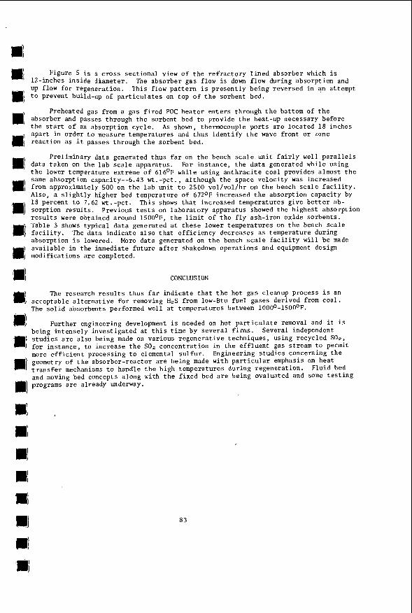
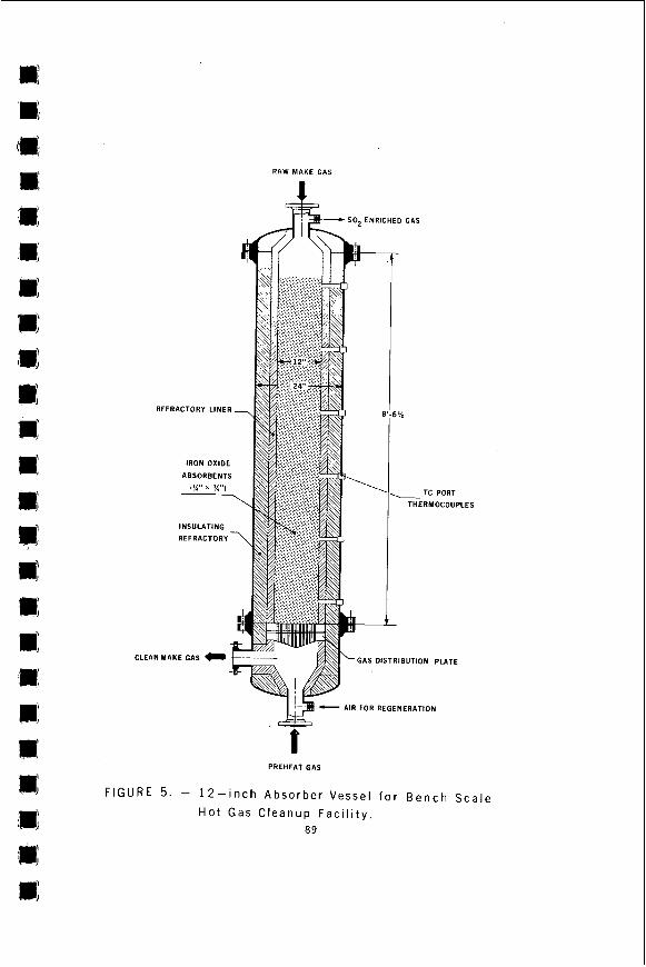
. Figure 5 i s a c ros s sec t iona l view c f t h e r e f r a c t o r y l i n e d absorber which is 12-lnches in s ide diameter. UP flow fo r regeneration.
The absorber gas flow i s down flow during absorption and This flow p a t t e r n i s p resen t ly being reversed in an attempt m; t o prevent build-up of p a r t i c u l a t e s on top of t h e sorbent bed.
1 absorber and Passes through t h e sorbent bed t o provide t h e heat-up necessary before the Start of an absorption cyc le . As shown, thermocouple p o r t s a r e located 18 inches apar t i n order t o measure temperatures and t h u s i d e n t i f y t h e wave f ron t o r zone mj react ion as i t passes through t h e sorbent bed.
m] da ta taken on t h e l a b s c a l e apparatus.
Preheated gas from a gas f i r e d POC hea te r e n t e r s through t h e bottom of the
Preliminary da ta generated t h u s fa r on t h e bench s c a l e u n i t f a i r l y well p a r a l l e l s
t h e lower temperature extreme o f 616'F while using a n t h r a c i t e coa l provides almost t h e Same absorption capacity--6.43 wt.-pct. , al though t h e space ve loc i ty was increased from approximately 500 on t h e l a b u n i t t o 2500 vol /vol /hr on t h e bench s c a l e f a c i l i t y . A l s o , a s l i g h t l y higher bed temperature of 6720F increased t h e absorption capac i ty by 18 percent t o 7.62 wt . -pct . sorpt ion r e s u l t s . r e s u l t s were obtained around 1500°F, t h e l i m i t of t h e f l y ash- i ron oxide sorbents . Table 3 shows typ ica l da t a generated a t these lower temperatures on t h e bench sca l e
absorption i s lowered. I ava i l ab le in the immediate f u t u r e a f t e r shakedown operat ions and equipment design J modifications a r e completed.
For ins tance , t h e da t a generated while using
81 I This shows t h a t increased temperatures give b e t t e r ab-
Previous t e s t s on l abora to ry apparatus showed the highest absorption
The data ind ica t e a l s o t h a t e f f i c i ency decreases a s temperature during More da t a generated on t h e bench s c a l e f a c i l i t y w i l l be made
. . .
CONCLUSION
@ The research r e s u l t s t hus f a r i nd ica t e t h a t t h e hot gas cleanup process i s an
I acceptable a l t e r n a t i v e f o r removing HzS from low-Btu f u e l gases derived from coa l .
1111 The s o l i d absorbents performed w e l l at temperatures between 1000°-15000F.
Further engineering development is needed on hot p a r t i c u l a t e removal and it i s
> s tud ie s a r e a l so being made on var ious r egene ra t ive techniques, using recycled S O a , being in t ense ly invest igated a t t h i s t ime by several f i rms . Several independent
f o r instance, t o increase t h e SO, concentrat ion in t h e e f f luen t gas stream t o permit more e f f i c i e n t processing t o elemental s u l f u r . geometry of t h e absorber-reactor a r e being made with p a r t i c u l a r emphasis on heat t r a n s f e r mechanisms t o handle the high temperatures during regenerat ion. and moving bed concepts a long with t h e f ixed bed a r e being evaluated and some t e s t i n g
Engineering s tud ie s concerning t h e
Fluid bed
m) programs a r e already underway.
83
REFERENCES
1. Reeve, L. Desulfur izat ion of Coke Oven Gas a t Appleby-Frodingham. J . I n s t .
2 . Catalyst Handbook, Imperial Chemical Indus t r i e s , Ltd., D i s t r ibu ted by Springer-
3. Abel, W . T . , F. G . Shu l t z , and P . F. Langdon. Removal of Hydrogen Su l f ide from
1
,E
E I ,E
Fuel, Vol 31, No. 210, J u l y 1958, pp 319-324.
Verlag, Inc . , New York (1970), p 53.
Hot Producer Gas by So l id Absorbents, BuMines R I 7947, 1974.
4. Shul tz , F. G. Removal o f Hydrogen S u l f i d e from Simulated Producer Gas a t Elevated Temperatures and Pressures . Proc. 2d I n t e r n a t . Conf. on Fluidized- Bed Combustion, National A i r Po l lu t ion Control Assoc., Hueston Woods S t a t e Park, College Corner, Ohio, October 4-7, 1970, 1972, pp 111-5-1-111-5-5.
Iron-Catalyzed Reduction o f NO by CO and H Z i n General Motors Symposium on NO Reduction, October 7-8, 1974.
5 . Clay, P . T. and Sco t t Lynn. Simulated Flue Gas.
6. Oldaker, E . C . , A. M. Poston, and W. L. Fa r r io r . Removal o f Hydrogen Su l f ide from Hot Low-Btu Gas with Iron Oxide-Fly Ash Sorbents . MERC/TPR-75/1. February 1975.
7. Oldaker, E . C . , A. M. Poston, and W . L. Fa r r io r . Hydrogen Rulfide Removal from
E Hot Producer Gas with A Sol id Fly Ash-Iron Oxide Sorbent. June 1975.
MERC/TPR-75/2,
8. Fa r r io r , W . L . , A. M. Poston, and E . C . Oldaker. Regenerable Iron Oxide-Silica Sorbents for Removal o f HaS from Hot Producer Gas. University of Kentucky, January 6-7, 1976.
4 th Energy Resource Conf., a 9. Oldaker, E . C . , A. M. Poston, and W . L. Fa r r io r . Laboratory Evaluation of Ul
‘rn ‘rn
Propert ies of Fly Ash-Iron Oxide Sorbents f o r HzS Removal from Hot Low-Btu Gas 170th National Meeting ACS, Vol 20, No. 4 , pp 227-237, August 24-29, 1975, Chicago, I L .
10 . A l t i e r i , V. J. Gas Analyses and Tes t ing of Gaseous Mater ia ls , American Gas Association, N e w York, 1st Ed i t ion , pp 339-340, 1945.
11. Friggens, G. R . and A. W. Hall. Nuclear Gages f o r Monitoring Coal Bed of Commercial Scale Pressurized Gas Producers. BuMines RI 7794, 1973.
84
GAS METERING
-*- WATER A DRY GAS DUST TAR
NITROGEN HYDROGEN
-1 HYDROGEN SULFIDE METHANE CARBON MONOXIDE ,~ CARBON DIOXIDE
TO TUTWEILER H Z S
llrl F I G U R E 1. - F l o w D i a g r a m o f A p p a r a t u s f o r M e a s u r i n g S o r p t i o n C a p a c i t y mi
a 1; m1 3: 1E
85
z + a lx 0
0
IC
4- -
FIGURE 2 . - S o r p t i o n C a p a c i t i e s A c h i e v e d D u r i n g T h i r t y A b s o r p t i o n R e g e n e r a t i o n Tes ts
86
+ Y
I
._ u
LL m
V
m c7
0 I U c
v)
c
m L
al u 2 U 0
a al
L
I
m
C O A L
MAKE GAS
T O C Y C L O N E
3" G R A T E
D R I V E S H A F T Q 4Ql.
A I R & S T E A M
F I G U R E 4. - 16-inch G a s P r o d u c e r f o r B e n c h S c a l e H o t
G a s C l e a n u p F a c i l i t y . 88
CLEl
RAW MAKE GAS
1 =- SO., ENRICHED GAS
REFRACTORY LINER
IRON OXIDE
ABSORBENTS
THERMOCOUPLES
GAS DISTRIBUTION PLATE
AIR FOR REGENERATION
PREHEAT GAS
FIGURE 5 . - 1 2 - i n c h A b s o r b e r Vesse l f o r B e n c h S c a l e
H o t Gas C l e a n u p F a c i l i t y . a9
Sorbent Composition
55% s i l i c a f 45% FeZO5
55% s i l i c a + 45% FeZ03 + 15 b e n t o n i t e
6 m l sodium s i l i c a t ; / l b 55% s i l i c a + 45% Fe20 +
75% f l y ash + 25% FeZ03
75% f l y ash + 25% Fez03 + 1 % b e n t o n i t e
75% f l y a sh f 25% FeZ03 I
10 ml sodium r i l i c u t c l l b
' hys i ca l S t r e n g t h Sur face Area H2S Sorpt ion Capacity lblem 31 75 ~T wt. - C t .
68 2 2 . 8
16 0 . 9 11 .5
59 1 . 5 10 .5 I
69
TABLE 1 - D a t a I n d i c a t i n g E f f e c t o f A d d i t i v e s O n S o r p t i o n C a p a c i t y a n d P h y s i c a l S t r e n g t h
11.21
15.91
90.01 16.38
91.LO 15.23
109.38
6.28
5.15
5 . n
5.50
6.m
7.25
501
563
510
581
529
5b9 - T A B L E 2 - T y p i c a l D a t a F r o m S i x o f T h i r t y S o r p t i o n
C a p a c i t y T e s t s
Time t o break th rough , ,h r s
Producer gas f low rate , scFh 7500.00 7322.94
Space velocity, vo l /vo l /h r
Gas t o breakthrough, s c f 34,975 40,992
Tota l HZS absorbed, grams 6544.8 7711.2
Weight percent 6 . 4 3 7.60
Percent o f t o t a l 82.61 82.07 (us ing 100 g r a i n d l 0 0 s c f as breakthrough)
T A B L E 3 - S o r p t i o n D a t a O b t a i n e d D u r i n g R e g e n e r a t i o n S t u d y o n B e n c h S c a l e H o t Gas C l e a n u p F a c i l i t y
90
H I G H TEMPERATURE SULFUR REMOVAL SYSTEM DEVELOPMENT FOR THE WESTINGHOUSE FLUIDIZED BED COAL GASIFICATION PROCESS
D. L. Keairns , R. A. Newby, E. P. O ' N e i l l , D. H. Archer Westinghouse Research Labora tor ies
P i t t s b u r g h , Pennsylvania 15235
ABSTRACT
High temperature sul.fur removal can be achieved wi th calcium
based sorbents ( e . g . dolomite) i n f l u i d i z e d bed c o a l g a s i f i c a t i o n systems
now being developed f o r power genera t ion . The use of dolomite o f f e r s
t h e opportuni ty t o meet environmental emission s tandards , t o minimize
energy losses , and t o reduce e l e c t r i c a l energy c o s t s .
I n a d d i t i o n t o achiev ing t h e removal o f s u l f u r from t h e low
Btu gas , t h e complete s u l f u r removal system must b e i n t e g r a t e d w i t h t h e
t o t a l power p l a n t and environment t o a s s u r e c o m p a t i b i l i t y . C r i t i c a l
requirements t o achieve a commercial system inc lude e s t a b l i s h i n g c r i t e r i a
f o r "acceptable" sorbents , e s t a b l i s h i n g i n t e g r a t e d s u l f u r removal/
g a s i f i c a t i o n process des ign parameters , p r e d i c t i n g t r a c e element r e l e a s e ,
p red ic t ing sorbent a t t r i t i o n , developing an economic regenera t ion and/or
once-through process o p t i o n , developing a s p e n t s o r b e n t process ing system,
and e s t a b l i s h i n g s a f e and r e l i a b l e d i s p o s i t i o n o p t i o n s f o r spent s o r b e n t .
Design and o p e r a t i n g parameters are being developed and p o t e n t i a l p rocess
l i m i t a t i o n s i d e n t i f i e d .
This work is being performed as p a r t of t h e Westinghouse Coal G a s i f i c a t i o n Program. The p r o j e c t i s be ing c a r r i e d out by a six-member industry/government par tnersh ip comprising ERDA, Publ ic Serv ice of Indiana, Bechtel , AMAX Coal Cb., Peabody Coal C b . and Westinghouse. This work has been funded wi th f e d e r a l funds from t h e Energy Research and Development Adminis t ra t ion under c o n t r a c t E(49-18)-15114. The content of t h i s p u b l i c a t i o n does not n e c e s s a r i l y r e f l e c t t h e views o r p o l i c i e s of t h e funding agency.
91
INTRODUCTION
The product ion of a low Btu f u e l gas from c o a l f o r combined
c y c l e e l e c t r i c power genera t ion provides t h e p o t e n t i a l f o r improved
thermal e f f i c i e n c y and reduced power c o s t s compared wi th convent ional
power p l a n t s wi th f l u e gas d e s u l f u r i z a t i o n and can provide acceptab le
environmental impact. The a b i l i t y t o produce t h e low Btu gas a t e leva ted
p r e s s u r e (e.g. 1500 kPa) w i t h removal of s u l f u r and p a r t i c u l a t e s from
t h e high temperature gas (e.g. 800-900'C) w i l l enable t h e maximum thermal
e f f i c i e n c y t o be achieved. Calcium-based sorbents , such as l imestone
and dolomite , have been proposed for t h e h igh temperature s u l f u r removal.
Westinghouse has been working on t h e development of a mul t i -
s t a g e f l u i d i z e d bed g a s i f i c a t i o n process f o r combined c y c l e power
genera t ion s i n c e 1970. ('")
and o p e r a t i o n of a gasifier/power-generating p l a n t on a s c a l e
which w i l l demonstrate t h e commercial opera t ion of t h e process . An
i n t e g r a t e d program is underway to proceed from bench-scale l a b o r a t o r y
r e s e a r c h through p i l o t s c a l e development and system des ign and eva lua t ion
t o t h e opera t ion of a demonstrat ion p l a n t . The p i l o t development is now
be ing c a r r i e d o u t i n a 15 ton/day process development u n i t .
The goa l of t h e program is t h e i n t e g r a t i o n
Westinghouse i s i n v e s t i g a t i n g gas c leaning systems f o r high
temperature opera t ion (800-9OO0C), in te rmedia te temperature o p e r a t i o n
(e .g . 65OoC), and low temperature opera t ion . Work has been c a r r i e d out
on both s u l f u r removal and p a r t i c u l a t e c o n t r o l systems. This document
is l i m i t e d t o an overview of t h e h igh temperature s u l f u r removal system
development work o n calcium-based sorbents . This system was s e l e c t e d
for t h e base c m c e p t based cn the p o t e n t i a l f o r high system e f f i c i e n c y
and t h e h i g h k i n e t i c e f f i c i e n c y of removing hydrogen s u l f i d e under t h e
proposed o p e r a t i n g condi t ions wi th an economically a v a i l a b l e sorbent .
A l t e r n a t e systems, such a s t h e u s e o f i r o n oxide or low temperature
processes , have n o t been excluded as candida tes f o r t h e demonstrat ion
p l a n t and a r e a l s o being s t u d i e d . An in te rmedia te temperature process
is a t t r a c t i v e i n t h a t i t reduces t h e m a t e r i a l s problems whi le main ta in ing
a r e l a t i v e l y high p l a n t e f f i c i e n c y .
92
m e I
The approach to the development of the calcium-based sulfur
removal system includes laboratory experimental programs utilizing
Pressurized thermogravimetric analysis, pressurized fluidized bed
reactors, and physical and chemical characterization to develop basic
data and t o develop screening techniques; data analysis to develop design criteria; systems analyses to assess the technical,economic, and
environmental impact of alternate sulfur removal system concepts and
to assess the impact of these alternatives on the total power plant.
SULFUR REMOVAL SYSTEM
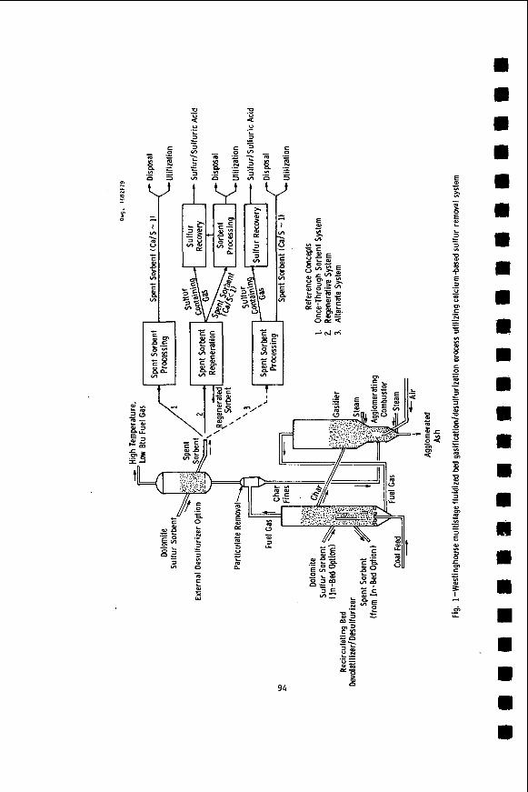
The basic gasification process utilizing the high temperature
calcium-based sorbent system is illustrated in Figure 1. The gasifi-
cation process has been described. ("*)
options are indicated in Figure 1: in-bed desulfurization and external
desulfurization. In situ desulfurization of the fuel gas within the
recirculating bed devolatilizer combines the sulfur removal and coal
devolatilization in a single vessel. This approach requires compatible
coal and sorbent behavior and the ability to separate sorbent and char.
The external desulfurizer requires a separate vessel and associated
components but provides greater flexibility. Both systems are being
assessed through process simulations, PDU operation, and engineering
analyses.
The sulfur removal process
Two basic sulfur removal systems have been identified and
investigated:
The reference once-through system and regenerative system concepts are
illustrated in Figure 1. An alternate once-through system concept is
also indicated which has been considered. A number of spent sorbent
processing and regeneration processes have been investigated.
a number of disposal and utilization options are available. These
process alternatives will be discussed in the following sections.
options such as pretreatment of the sorbent to improve its attrition
behavior or sulfur capacity and the addition of "getters" to remove
alkali metals to prevent gas turbine corrosion are also being considered.
once-through sorbent operation and regenerative operation.
Similarly,
Other
93
t v t v
94
E
rn rn rn m
m m rn
m m m
SULFUR REMOVAL
Laboratory and engineering studies are being carried out to
evaluate two areas critical to sulfur removal: sulfur removal process
options and sorbent selection. These efforts parallel development work
planned for the process development unit related to these areas.
Process Options
The technical and environmental performance and economic
aspects of sulfur removal process options are being evaluated in order
to provide a basis for selection and to define process development
requirements. Two major options have been identified: once-through
sorbent operation versus regenerative sorbent operation and in situ
(devolatilizer) desulfurization versus external dessulfurization.
Both once-through sorbent and regenerative sorbent
desulfurization behavior are being developed. The PDU is currently designed for once-through scrbcnt operation.
through and regenerative sulfur removal exist with factors such as
sorbent consumption, sorbent attrition, trace element release, and system complexity and operability being important considerations.
Sorbent Selection
Trade-offs between once-
Both limestone (CaC03) and dolomite (MgCa(C03)2) can be used
as sulfur sorbents under full gasification conditions at high fuel
temperatures, but laboratory studies show that there are several
factors which restrict their use under specific design conditions,
and which impact on both the desulfurization process, and the overall
power generation plant.
Limestone reacts with hydrogen sulfide only when it has
calcined, a kinetic rather than a thermodynamic restriction. (3 ) For
atmospheric pressure applications, calcined limestone should achieve
90% desulfurization of fuel gases at calcium to sulfur molar feed ratios of %1.8/1. ( 4 )
confirm this projection. ( 5 )
at pressure, calcium carbonate is the stable form of the reacting
sorbent, and limestone is inactive.(6)
Recent fixed-bed tests by the Bureau af Mines
However for desulfurizing low Btu gas
95
For dolomite, at Ca/S feed ratios of < 1.211.0, projections from
laboratory data show that almost complete reaction of the calcium content
m y be attained while fixing 90% of the fuel sulfur in solid form, for
particle sizes up to 2000 microns.")
apparently limited by diffusion of reactant into the solid.
variation was noted in testing dolomites ranging from the relatively pure massive-grained Canazn dolomite (Connecticut), Zhrough the sucrose-type
dolomites (Glasshouse, Ohio), to the impure Tymochtee dolomite
(Ohio'). (2c) have demonstrated the excellent sulfur capture abilities of dolomite
with simulated fuel gasek.(8) The Bureau of Mines tests showed that
half-calcined dolomite demonstrated improved sulfur removal at 1500°F
over that noted at 1400°F. (5) desulfurizing temperature to 1600aF, they noted a drastic loss of
desulfurizing action as the dolomite decomposed to the fully-calcined
state. While this test has not been simulated in laboratory tests,
precalcined dolomites have shown similar sulfidation reaction rates to
those noted with half-calcined dolomite. Further tests are evidently
required to explore this discrepancy.
For larger particle sizes reaction is
No significant
Fluidized-bed tests by Conoco Coal Development Co.*
However when they increased the
The major limitations on using dolomites arise from trace-
element emissions, attrition rates, and suitability for processing by
direct air oxidation for disposal.
One of the major concerns in operating a gas turbine with the
low Btu gas is the extent to which corrosion and erosion will limit the
lifetime of the metal alloys used in the blades and stators. (2c) The
alkali metals, particularly sodium, induce hot corrosion (accelerated
oxidation or sulfidation attack of the metal) by depositing oxygen-
excluding liquid films of sulfates on the metals. Dolomites contain
sodium and potassium as impurities, and they are found both as clay
mineral components, and as more volatile compounds - probably chlorides, in the carbonate rock. The range of these impurities in dolomites is
enormous, e . g . Na (5-330 ppm), and K(5-6,500 ppm). (2c) Recent studies
* Conoco Coal Development Co. arid Consolidation Coal Co. are used in this Paper. Consolidation Coal Cb. is used when work was performed under that organizational name.
96
of the release of alkalis from dolomites into fuel gas have demon-
strated that significant fractions of the alkali can enter the gas
stream, and that this release is essentially complete within a short
fraction of the expected sorbent residence times. (") The resulting
alkali level in the turbine feed gas is substantially in excess of
that permitted by current empirical specifications for oil-fired
turbines (-10 ppb Na). There are several approaches uhich may he taken to avoid this problem. First of all, a low-alkali dolomite may be
chosen as sulfur sorbent. This is likely to be the result of an
unusually fortuitous selection of power plant site. Although the
available analysis of dolomites show significant variations in alkali
content within a particular geological stratum from quarry to quarry
and from stratum to stratum within a quarry, the majority of the
analyses are of sufficient vintage to be suspect. However we have
noted a consistant increase in alkali content with increasing quarry
depth, so that material quarried at a depth of 100 ft may contain
one order of magnitude more alkali than that quarried near the
surface. c9) An alternative to selecting a "clean" dolomite, is to
pre-heat the material t o release the alkalis before using the stone
as a sulfur sorbent. The bulk of the alkali release OCCUKS within
20 minutes of heating the stone to *870"C, and after this initial release the rate of alkali loss is extremely low. The third possi-
bility is to add materials such as aluminosilicates to the sorbent
bed, or at a particulate filtration stage to getter the alkalis.
It should be emphasized that several critical questions cannot be
satisfactorily answered without further research. The extent to
which chlorine from the coal may strip alkalis from dolomite and
coal char must be investigated. In addition the turbine tolerance t o the combined presence of sodium and potassium requires further
experimental and theoretical investigation. (") of minor elements such as the alkalis in coal gasification is not well
known. Recent studies at the Bureau of Mines show considerable
The chemical fate
97
r e l e a s e of c h l o r i n e t o t h e g a s phase - presumably a s HC1.(2c)
t h e mass balance f o r a l k a l i s i n t h e i n p u t and o u t p u t s o l i d s w a s n o t
s u f f i c i e n t l y p r e c i s e to e s t i m a t e t h e l e v e l s of a l k a l i i n t h e
gas phase.
However
I t should a l s o be noted t h a t t h e t u r b i n e t o l e r a n c e t o a l k a l i s
i s t h e o r e t i c a l l y a f u n c t i o n of t o t a l c h l o r i n e (as HC1) l e v e l s i n t h e gas
phase.
c o r r o s i v e s u l f a t e d e p o s i t s .
d i r e c t gaseous a t t a c k of t h e p r o t e c t i v e oxide s c a l e s on the t u r b i n e a l l o y s
The combination of h igh c h l o r i n e and high a l k a l i l e v e l s may avoid
This apparent advantage w i l l be l i m i t e d by
SORBENT REGENERATION
The consumption of sorbent by t h e power p l a n t s u l f u r removal
system may be minimized by u t i l i z i n g a processing s t e p t o regenera te
t h e u t i l i z e d sorbent t o a n a c t i v e form. I d e a l l y t h e sorbent would be
e n t i r e l y r e c o n s t i t u t e d by t h e regenera t ion process , but i n r e a l i t y
f r e s h sorbent w i l l be requi red due t o d e a c t i v a t i o n of t h e regenera ted
sorbent and a t t r i t i o n l o s s e s . Regenerat ion of t h e s u l f i d e d sorbent
r e q u i r e s t h a t t h e captured s u l f u r be converted t o some o t h e r form,
preferab ly e lementa l s u l f u r of commercial q u a l i t y . The purge stream
of s p e n t sorbent must be processed to some environmental ly acceptab le
o r u s e f u l form. This combination of f u n c t i o n s , sorbent regenera t ion-
s u l f u r recovery-spent sorbent process ing , must r e s u l t i n a n i n t e g r a t e d
process which is compatible wi th t h e c o a l g a s i f i c a t i o n process and i s
economically and environmental ly acceptab le .
Regeneration Process Options
A v a r i e t y of p o t e n t i a l r e g e n e r a t i o n process concepts have
been evaluated f o r t e c h n i c a l f e a s i b i l i t y .
s e l e c t e d f o r f u r t h e r engineer ing assessment: (1) Sorbent regenera t ion
by r e a c t i o n of s u l f i d e d s o r b e n t wi th steam and carbon d i o x i d e t o
genera te carbonated sorbent and a hydrogen s u l f i d e gas stream;
(2) sorbent regenera t ion by r e a c t i o n o f s u l f i d e d sorbent wi th oxygen
t o genera te t h e oxide form of t h e s o r b e n t and a s u l f u r d ioxide gas
stream. The chemical r e a c t i o n s a r e w r i t t e n , r e s p e c t i v e l y .
Two concepts have been
and
CaS + H20 + C 0 2 s C a C 0 3 + H2S
Cas + 312 02=Ca0 = SO2
(1)
(2 )
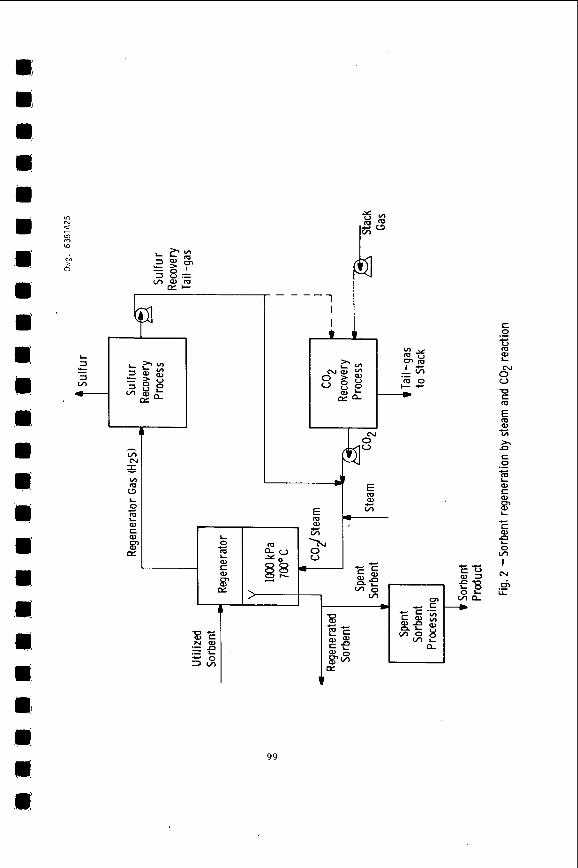
Steam and CO Regenerat ion Scheme 2
A schematic f low diagram f o r t h e sorbent regenera t ion system
based on t h e steam and C02 r e g e n e r a t i o n r e a c t i o n i s shown i n F igure 2.
This process is a l s o be ing eva lua ted by Consol ida t ion Coal. (')
9a
b
I
Y "2 r
E m
99
c 0 .- H E 0"
5
u u C m
al c VI
)r .n c 0 .- m i al C
L E c K a
0 v) f
I rJ
.- ch U
Three major components a r e involved i n t h e sorbent r e g e n e r a t i o n
system: t h e regenera tor r e a c t i o n v e s s e l , t h e s u l f u r recovery process
and the C 0 2 recovery process .
a v a i l a b l e f o r s u l f u r recovery from H2S g a s s t reams.
process s e l e c t i o n w i l l depend l a r g e l y on two f a c t o r s - t h e l e v e l of H S 2 i n t h e r e g e n e r a t o r gas and t h e optimum scheme f o r steam and C02 u t i l i -
zat ion. An H S volume percent of about 15% w i l l permit t h e a p p l i c a t i o n
of convent ional Claus process technology.
w i l l r e q u i r e e i t h e r pre l iminary c o n c e n t r a t i n g of t h e HpS-gas, fol lowed
by Claus s u l f u r recovery , concent ra t ing and r e c y c l e of t h e Claus p l a n t
t a i l - g a s , or a p p l i c a t i o n of a l t e r n a t e s u l f u r recovery processes s u i t a b l e
f o r low H S c o n c e n t r a t i o n s such as t h e S t r e t f o r d process (Palph M . Parsons
CO. and Union O i l Co. of C a l i f o r n i a ) .
A number of commercial p rocesses are
The s p e c i f i c
2 Lower H2S concent ra t ions
2
Make-up C02 f o r t h e r e g e n e r a t i o n r e a c t i o n can be suppl ied by
power p l a n t s t a c k gas p u r i f i c a t i o n .
t a i l - g a s may also r e q u i r e p u r i f i c a t i o n i n order t o maintain low l e v e l s
of impur i t ies (N2, 02, e t c . ) in t h e CO / s t e a m r e a c t a n t stream. Numerous
commercial p rocesses a r e a v a i l a b l e f o r COP recovery - Selexol , Benf ie ld ,
Catacarb, S u l f i n o l , and many o t h e r s . The economics and environmental
performance of each of t h e s e p r o c e s s e s w i l l d i f f e r f o r t h i s a p p l i c a t i o n
and r e q u i r e eva lua t ion .
A p o r t i o n of t h e s u l f u r recovery
2
The s i n g l e most important f a c t o r i n f l u e n c i n g t h e economics
and performance o f t h i s r e g e n e r a t i v e scheme i s t h e regenera tor gas H2S
concent ra t ion . The s i z e of t h e r e g e n e r a t o r r e a c t i o n v e s s e l , t h e s i z e and
complexity of t h e s u l f u r recovery p r o c e s s , and t h e r a t e of steam
consumption and a u x i l i a r y power usage a l l i n c r e a s e as t h e H S concen-
t r a t i o n is reduced. Es t imates of t h e H S concent ra t ion based on
r e a c t i o n k i n e t i c s and thermodynamics a r e about 3-5 volume %.
2
2
Other f a c t o r s such as regenera ted sorbent a c t i v i t y , t h e
requi red r a t e of sorbent c i r c u l a t i o n , t h e e f f e c t of t h e regenera t ion
process on t h e power p l a n t a v a i l a b i l i t y , e t c . , are a l s o important t o t h e process f e a s i b i l i t y .
100
Oxygen Regeneration Scheme
A schematic flow diagram of the sorbent regeneration system
based on the oxygen regeneration reaction is shown in Figure 3.
atmospheric pressure version of this process has been applied by
Esso ( U . K . ) for their CAFB gasification process. (lo)
An
This regeneration process is conceptually simpler than the
steam/Co2 regeneration process since only two major process components
are involved: the regenerator reaction vessel and the sulfur recovery
process. On the other hand, the oxygen regeneration process is necessarily a higher temperature regeneration scheme with the potential
for greater sorbent deactivation.
at pressures of 200 to 1000 kPa (2 to 10 atmospheres) and temperatures of 1000 to 1100°C with SO2 volume percents of 2 to 4 expected for the
high pressure system and up to 10% for the low pressure system.
The regenerator could be operated
Sulfur recovery from dilute SO2 streams is generally more
expensive and complex than from dilute H S streams. The most highly commercialized sulfur recovery process for this application is the
Allied Chemical direct reduction process (using methane or clean liquid fuels as reductant) which will work effectively on SO2 streams
down to about 4 volume % SO depending upon the oxygen content of
(I1) or lower SO concentrations a commercial concentrating the gas.
step such as the Wellman-Lord process must be used. Other sulfur
recovery processes applicable to SO2 streams which are in early stages
of commercialization are the Foster Wheeler RESOX process (which uses
coal as the SO reductant), the ASARCO-Phelps Dodge process, the
Bureau of Mines Citrate process, the Westvaco activated carbon process,
and the Stauffer Aquaclaus process.
2
2
2
2
While the low pressure oxygen regeneration results in a
much greater SO2 concentration in the regenerator gas, the technological
and reliability problems involved in circulating the hot sorbent
between vessels with greatly different operating pressures may not be
easily overcome. Again, as in the steam/CO regeneration process, 2
101
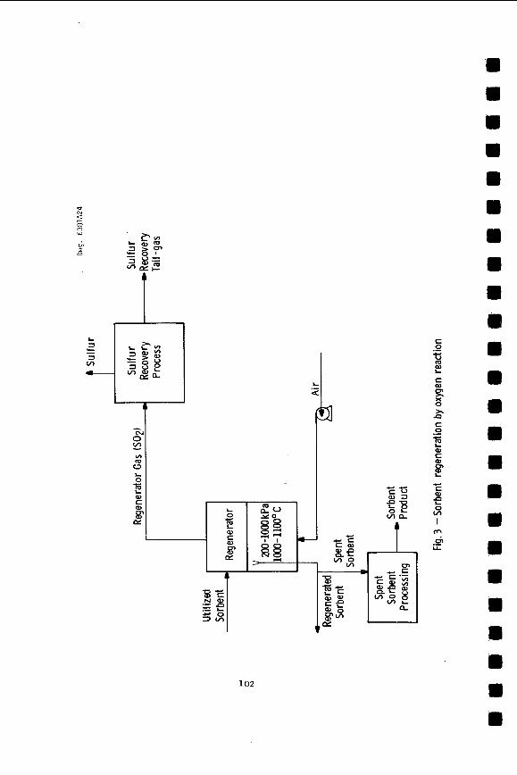
102
c 0 .- 5 m L
c
B 0
a c 0 .- E
f 0) c a
c c a L 0 v)
n
I M
.- 6 I&
the concentration of the sulfur-bearing species in the regenerator gas has a dominant influence on the economics and performance of the
regeneration system.
greater SO2 concentrations (thermodynamically) but may increase
sorbent deactivation.
Increased operating temperatures will provide
The overall economics, technical performance and environ-
mental impact of these two sorbent regeneration concepts must be
evaluated in order t o determine the feasibility of sorbent regeneration,
in order t o select the most promising regeneration scheme and in
order to identify the optimum components to be utilized in the
regeneration scheme. The critical interfaces between the coal
gasification system, the power generation system, the spent sorbent
processing system and the sorbent regeneration system are being
considered in the evaluation.
Regeneration Chemistry
It was noted by Mellor(12) that the equilibrium CaS + H20 + CO2SCaCO carbonate, because of the low concentration of hydrogen sulfide
produced.
at pressure. (I3) calcium sulfide is rapidly deactivated, and TG studies show that only 20% of the calcium sulfide is readily converted t o calcium carbonate
after 10 cycles of sulfidation/regeneration, at 704'12. (b)
+ H2S cannot be used to reform calcium 3
This problem may be overcome by carrying out the reaction However the early work by Pell(14) showed that
An encouraging feature is that the rate of sulfidation
decreases very slowly as the stone is recycled and the regenerated sorbent is almost as reactive as fresh stone. (6 )
The initial rate of regeneration is very fast and is
apparently limited by production of the equilibrium level of hydrogen
sulfide, since the initial rate increases on dropping the temperature
from 700°C to 650°C. However, when the regeneration has proceeded to
a certain stage (50% after 2 cycles, or 20% after 10 cycles), the rate
W 103
f a l l s o f f by more than one order of magnitude. A t t h i s s t a g e t h e
r a t e can be increased by i n c r e a s i n g the r e a c t i o n temperature , so t h a t
a t 870"C, a l l t h e s u l f i d e i s r e a d i l y regenera ted . However, t h e
equi l ibr ium concent ra t ion of H S becomes so unfavorable t h a t t h i s i s
n o t a t e c h n i c a l l y f e a s i b l e s o l u t i o n . 2
The d e a c t i v a t i o n of calcium s u l f i d e thus becomes a chemical ly
l i m i t i n g s t e p i n regenera t ion . An a d d i t i o n a l c l u e t o t h e mechanism of
deac t iva t ion i s g iven by t h e f a c t t h a t when calcium s u l f i d e is prepared
by reduct ion of calcium s u l f a t e , a t 820 o r 850"C, f o r 2 hours , on ly
26% of t h e calcium s u l f i d e is regenerable . (15)
deac t iva t ion may be p a r t l y due t o t h e longer res idence time a t higher
temperatures than i s customary i n s u l f i d a t i o n r e a c t i o n s , s i n c e
s u l f i d a t i o n t a k e s about 15 minutes.
shown t h a t longer exposure a t h igh temperatures (871°C) during
s u l f i d a t i o n , reduces t h e e x t e n t of regenera t ion , a s does increas ing t h e
temperature of s u l f i d a t i o n t o 950"C, whi le lowering the s u l f i d a t i o n
temperature t o 7 5 O o C i n c r e a s e s t h e e x t e n t of regenera t ion . The
deac t iva t ion of t h e calcium s u l f i d e i s always accompanied by some
growth of calcium s u l f i d e p a r t i c l e s i z e , and by e x t e n s i v e growth of
magnesium oxide c r y s t a l l i t e s i n proximity t o t h e calcium s u l f i d e a s
determined by X-ray d i f f r a c t i o n l ine-widths .
This increased
Recent s t u d i e s by Sun(16) have
It can be concluded t h a t a cont inuous regenera t ion system
must o p e r a t e wi th a low s u l f u r d i f f e r e n t i a l between the calcium
s u l f i d e conten t of t h e d e s u l f u r i z e r and regenera tor e x i t s t reams.
Squires(17) has demonstrated t h a t t h e e x t e n t o f regenera t ion
improves dramar ica i ly w i t h p a r t i a l p r e s s u r e s of s t e a m of 15 atmospheres,
and t h a t 50% of t h e calcium s u l f i d e is regenerable . While h i s s u l f i d a t i o n
r e a c t i o n condi t ions (700'C) may not have been s e v e r e enough t o cause
growth of the magnesium oxide around the calcium conta in ing c r y s t a l l i t e s ,
t h e improved d i f f u s i v i t y of t h e r e a c t a n t gases through t h e s o l i d
caused by r a i s i n g the H 2 0 / C 0 2 r a t i o may s i g n i f i c a n t l y improve t h e
e x t e n t of regenera t ion b e f o r e t h e r e a c t i o n rate dwindles. P e l l ' s
104
rn m
m
m m
m
0
lli
0 I)
m M
m m
m
m
rn 0
0
rn
e m
R
D
rn rn m m
m m
a
experiments c a r r i e d out a t a 111 r a t i o a t 15 atm i n d i c a t e l i t t l e i f
any improvement over the TG v a l u e f o r e x t e n t of regenera t ion .
average e x t e n t of regenera t ion f o r 20 c y c l e s is %13%, so t h a t each mole
Of calcium w i l l remove 2 .7 moles of s u l f u r v i a t h e ' regenerator , and one
mole of s u l f u r v i a t h e spent sorbent stream.
The
The calcium t o s u l f u r molar make-up feed r a t e requi red i s
t h e r e f o r e 0.25/1 unless a t t r i t i o n l o s s e s are g r e a t e r than 5% of t h e
t o t a l calcium per cyc le , i n which case reducing t h e a t t r i t i o n l o s s
becomes more important than improving t h e r e g e n e r a b i l i t y of t h e s tone .
Consol idat ion Coal Co. (') have repor ted a t t r i t i o n l o s s rates o f less
than 1% p e r cyc le ; however it is not known i f such performance can be
projected t o l a r g e s c a l e u n i t s .
SPENT SORBENT DISPOSITION
The once-through and r e g e n e r a t i v e process opt ions w i l l produce
a dry, p a r t i a l l y u t i l i z e d dolomite o r l imes tone wi th p a r t i c l e s up t o
6 mm i n s i z e . I n a d d i t i o n , f i n e p a r t i c l e s of sorbent (wi th some ash
and c h a r ) w i l l be c o l l e c t e d i n t h e gas p a r t i c u l a t e c o l l e c t i o n systems.
The composition of the sorbent f o r d i s p o s i t i o n w i l l depend on t h e
c h a r a c t e r i s t i c s of t h e o r i g i n a l s tone , t h e c o a l feed , t h e s e l e c t i o n
of t h e sorbent process ing system, and t h e process opera t ing condi t ions .
The major compounds i n t h e waste s t o n e from t h e d e s u l f u r i z e r o r
regenera tor u t i l i z i n g dolomite are calcium carbonate (CaC03), magnesium
oxide (MgO), and calcium s u l f i d e (Cas). Trace elements from t h e
sorbent and c o a l w i l l a l s o be present .
D i r e c t d i s p o s a l or u t i l i z a t i o n of t h i s m a t e r i a l i s not
considered t o be an o p t i o n which w i l l be g e n e r a l l y a v a i l a b l e . Thus,
processing of t h e spent sorbent has been incorpora ted i n the s u l f u r
removal system. The u l t i m a t e s e l e c t i o n and development of a spent
sorbent process ing scheme w i l l depend on many f a c t o r s r e l a t e d t o
the development of the d e s u l f u r i z a t i o n system and t h e regenera t ion
system. These f a c t o r s w i l l determine t h e n a t u r e of t h e spent sorbent
and t h e process ing requi red f o r t h e spent sorbent processing system.
Among t h e f a c t o r s t h a t w i l l a f f e c t t h e d i s p o s i t i o n of t h e sorbent a r e
the q u a n t i t y of spent sorbent , i t s chemical c h a r a c t e r i s t i c s ,
regula t ions , geographica l l o c a t i o n , and t h e market s i z e i n t h e c a s e of
u t i l i z a t i o n .
Process ing
A v a r i e t y o f spent sorbent process ing schemes have been
i d e n t i f i e d which could p o t e n t i a l l y convert t h e spent sorbent produced
i n a once-through o r r e g e n e r a t i v e o p e r a t i o n i n t o a m a t e r i a l s u i t a b l e
105
f o r d i r e c t d i s p o s a l o r u t i l i z a t i o n . (4'19)
been developed t o convert calcium-based s o r b e n t s conta in ing calcium
s u l f i d e to environmental ly a c c e p t a b l e forms f o r d i s p o s a l or u t i l i z a t i o n .
Work by Westinghouse on t h e CAFB f l u i d i z e d bed g a s i f i c a t i o n /
d e s u l f u r i z a t i o n process , under c o n t r a c t t o EPA, has i d e n t i f i e d spent
sorbent process ing opt ions . ( 4 )
c a r r i e d o u t as a n extension of t h i s work t o permit t e c h n i c a l and
economic assessments of these processes . These t e s t s w i l l provide
information d i r e c t l y a p p l i c a b l e t o t h e s u b j e c t c o a l g a s i f i c a t i o n /
d e s u l f u r i z a t i o n process . Spent sorbent process ing systems b e i n g
considered i n c l u d e dry o x i d a t i o n , o x i d a t i o n p l u s carbonat ion,
deadburning, s l u r r y carbonat ion , dry s u l f a t i o n , h igh temperature
process ing wi th c o a l a s h , and low temperature process ing wi th c o a l ash.
Processing a l t e r n a t i v e s have
Experimental programs are now being
A dry o x i d a t i o n process which conver t s t h e spent sorbent
(calcium s u l f i d e ) from a once-through o r regenera t ive o p e r a t i o n i n t o a
calcium s u l f a t e m a t e r i a l has been s e l e c t e d as t h e base spent sorbent
process ing scheme. Experimental s t u d i e s and process s t u d i e s f o r t h e
d r y oxida t ion process a r e being performed as p a r t of t h e c u r r e n t
program.
Thermogravimetric s t u d i e s of t h e d i r e c t ox ida t ion of calcium
s u l f i d e t o calcium s u l f a t e have revea led some important f e a t u r e s of
t h e r e a c t i o n which must be cons idered i n process eva lua t ion .
F i r s t , i n most do lomi t ic s t o n e s , complete o x i d a t i o n o f t h e
s u l f i d e d s tone occurs r a p i d l y i n a i r a t 800"C, whi le s u l f i d e d l imes tones
conta in ing more than 30 molar % CaS and t h e s u l f i d e s of large-grained
dolomites a r e oxid ized incomple te ly .
Secondly, t h e r e a c t i o n i s extremely exothermic,
AHzg8= -912 kJ mole-', and i f t h e temperature of the r e a c t i n g s o l i d
is permitted t o r i s e t o h igher temperatures , s u l f u r dioxide w i l l be
106
m
emitted by one of two mechanisms.
oxidation to the oxide may OCCUK:
if low partial pressures of oxygen are developed in the system as a
result of the primary reaction, then calcium sulfide and calcium sulfate
interact to reject sulfur dioxide according to the reaction
In the first mechanism direct CaS + 3/2 02+Ca0 + SO2. However
3 CaS04 + Cas -4 CaO + 4 SO2. By carrying out the oxidation reaction in a fluidized bed reactor at
80OOC in excess air, both of these competing reactions may be avoided.
In thermogravimetric tests at 800"C, sulfur dioxide transients in the exit gas stream were accompanied by temperature excesses. Typically
32 moles of cold air per mole of calcium are required for heat
balance in a system operating at a 2/1 calcium to sulfur mole ratio
in the desulfurizer. Because of the large excess of air entering the
system, >3X stoichiometric, the particles should oxidize at'much the same rate a s they do in the TG apparatus; stone residence times greater
than 30 minutes are projected to ensure that oxidation is almost
complete (>90%).
The third feature of this reaction is that regenerated
stone which has experienced multiple sulfidation/regeneration cycles
is not completely oxidizable. A function of the calcium sulfide
which is inert in the regeneration reaction is also inert in the
oxidation reaction.
Based on the information available, the dry oxidation
process is considered attractive for once-through operation with
most dolomites. once-through operation with limestones OK for regenerative operation.
The primary concern is the environmental impact from sorbent disposal.
Further work is required to permit a comprehensive assessment of
dry oxidation. Work is proceeding to investigate other processing
opt ions.
This process does not appear as attractive for
107
Disposal
The environmental impact of any disposed material is a
function of its physical and chemical properties and the quantity
involved. Two disposal alternatives will be investigated: land and
ocean dumping. Environmental impact tests are planned to study the
direct disposal of material from the spent sorbent processing system.
These tests will be carried out using material produced in laboratory
units to investigate the affect of operating conditions and in the
prsccss development ilnit to determ,inr the environmental impact from
material produced in the integrated process.
Westinghouse has carried out environmental impact tests on
related materials as part of the CAFB fluidized bed gasification and
the fluidized bed combustion programs being carried out under
contract to EPA. (4 ’18 ’19920)
developed at Westinghouse to assess the potential water contamination
and heat release from disposing a spent bed limestone directly from a
gasification process and from the spent limestone after further
processing. These studies indicate the leachability and activity
can be significantly reduced by further processing.
from fluidized bed combustion processes has also been tested(18)
which indicates that if the calcium sulfide in the dolomite can be
converted to calcium sulfate through the dry oxidation process, the
material will be environmentally acceptable.
Leaching and activity tests have been
Spent dolomite
Utilization
The direct disposal of sorbent may not be possible or
Utilization of spent sorbent is an alternative permitted in all cases.
which has the potential to provide technically and economically
attractive by-product.
unprocessed spent sorbent include soil stabilization, land fill, concrete, refractory brick, gypsum, municipal waste treatment. Preliminary work has been carried out in this area. ( 4 , 2 0 , 2 1 )
Potential applications of processed or
108
m
a
m
rn
m m
m m
m H
rn
ASSESSMENT
High temperature sulfur removal with a fluidized bed coal
gasification system appears attractive based on available information.
A number of processing options are being developed which consider integration of the sulfur removal system with a low Btu gasification - combined cycle power plant and consider the total sulfur removal system
from sorbent selection to sorbent dispositioh.
removal system includes:
Assessment of the sulfur
Sulfur Removal: Dolomites are the preferred sorbent for the
Westinghouse coal gasification procesk.
of 9OX are projected with mean particle sizes between 1000 and 2000 p
and a calcium t o sulfur molar ratio of 1.2/1.0 for a once-through system.
Combined devolatilization/desulfurization is considered attractive but compatibility must be demonstrated. The external desulfurizer option
offers an alternative with greater flexibility. There appear to be
ample supplies of dolomite available.
Sulfur removal efficiencies
Sorbent Regeneration: Two regeneration concepts have been
selected for further study. Regeneration by carbon dioxide and steam
is technically feasible and is the preferred option. Calcium to sulfur
molar feed make-up is projected to be 0.25/1 based on attrition losses
c 5% of the sorbent per cycle. Commercial technology is available for
s u l f u r recovery from dilute H S or SO2 gas streams and for CO
Advanced systems, which may reduce costs, are not being incorporated
into the current development effort.
2 recovery. 2
x e n t Sorbent Disposition: In general, spent sorbent processing will be required for once-through o r regenerative operation due to the
calcium sulfide present in the sorbent.
are under investigation to permit disposal or utilization of the material.
Alternate processing schemes
A dry o x i d a t i o n process is a t t r a c t i v e f o r once-through o p e r a t i o n w i t h
most dolomitek. Prel iminary o x i d a t i o n t e s t s and environmental impact
tests i n d i c a t e t h i s process ing o p t i o n w i l l be economic and environmental ly
acceptab le . Pre l iminary tests on r e l a t e d m a t e r i a l s i n d i c a t e s u t i l i z a t i o n
of t h e spent sorbent may be p r a c t i c a l .
Sorbent S e l e c t i o n : General f a c t o r s t o be considered i n t h e
s e l e c t i o n of a sorbent are t h e d e s u l f u r i z a t i o n performance, t h e sorbent
r e g e n e r a b i l i t y , t h e spent sorbent p r o p e r t i e s , sorbent a t t r i t i o n behavior
arid t r a c e meta ls r e l e a s e behavior . Sodium, potassium, and c h l o r i n e
release is of p a r t i c u l a r importance t o c o n t r o l gas t u r b i n e cor ros ion .
Trace metals release t o t h e f u e l g a s may b e c o n t r o l l e d by s e l e c t i n g a
"pure" s o r b e n t , p r e t r e a t i n g t h e s o r b e n t or u t i l i z i n g a g e t t e r i n t h e
f u e l gas c leaning system. Avai lab le d a t a i n d i c a t e t h e t r a c e elements
can be c o n t r o l l e d t o meet t u r b i n e p r o t e c t i o n requirements . Fur ther
work i s requi red t o s p e c i f y t h e p r e f e r r e d method of opera t ion .
A once-through s u l f u r removal system u t i l i z i n g dolomite w i t h
a d r y o x i d a t i o n s p e n t s o r b e n t process ing system has been s e l e c t e d f o r
t h e r e f e r e n c e desigh. Fur ther development e v a l u a t i o n of t h e t e c h n i c a l
performance, economics, and environmental impact of t h e a l t e r n a t i v e
s u l f u r removal systems under c o n s i d e r a t i o n must be c a r r i e d o u t t o s e l e c t
t h e most,promising system.
schemes i n t o a n optimum high tempera ture s u l f u r removal system which i s
compatible wi th t h e c o a l g a s i f i c a t i o n power p l a n t i s t h e o b j e c t of t h e
development e f f o r t .
The i n t e g r a t i o n of t h e a l t e r n a t i v e process ing
110
m m
<rn
E
rn
m
6 rn rn rn rn 6
rn rn
I
m: :mi
I
I
REFERENCES
1. Archer, D. H., E. J . Vidt, D. L. Keairns, J. P. Morris, J. L. P Chan, "Coal Gasification for Clean Power Generation," Proceedings Third
International Conference on Fluidized Bed Combustion, November 1972
(NTIS Number PB-231 977).
"Advanced Coal Gasification System for Electric Power Generation,"
Westinghouse Electric Corp., Contract reports to ERDA/FE:
a) Interim Report No. 1, NTIS No. PB-236 971;
b) Interim Report No. 2 . NTIS No. FE-1514-T-4;
c) Interim Report No. 3
2 .
3 . O'Neill. E. P., D. L. Keairns, and W. F. Kittle, "Kinetic Studies Related t o the Use of Limestone and Dolomite as Sulfur Removal Agents on Fuel Processing," Proceedings Third International
Conference on Fluidized Bed Combustion, November 1972.
NTIS NO. PB-231 977
4. Keairns, D. L.. R. A. Newby, E. J . Vidt, E. P. O'Neill, C. H. Peterson, C. C. Sun, C. D. Buscaglia, and D. H. Archer,
"Fluidized Bed Combustion Process Evaluation - Residual Oil Gasification/Desulfurization Demonstration at Atmospheric
Pressure," two volume contract report to EPA, March 1975, EPA report number EPA-650/2-75-027 a and b, NTIS No. PB-241 834
and PB-241 835.
5. Abel, W. T., and E. P. Fisher, "Limestone to Reduce Hydrogen Sulfide
from Hot Produced Gas." U.S:E.R.D.A., MERC/RI-75/3, January 1976.
6. Keairns, D. L., E. P. O'Neill and D. H. Archer, "Sulfur Emission Control with Limestone and Dolomite in Advanced Fossil Fuel
Processing," Symposium Proceedings - Environmental Aspects of Fuel Conversion Technology, EPA-650/2-74-118. October 1974.
7. O'Neill, E. P. and D. L. Keairns, "Selettion of Calcium-Based
Sorbents for High-Temperature Fossil Fuel Desulfurization,"
paper presented at the 80th National A.I. Ch. E. Meeting,
Boston, September 1975, to be published in AIChE Symposium
Series Volume.
:i: I
111
a.
9.
10.
11.
12.
13.
14.
15.
16.
17.
REFERENCES (cont lnued)
Carran, G. P . , J. T. Clancey, B. Pasck, M. P e l l , G. D. Rutledge
and E. Gorin. "Product ion of Clean Fuel Gas from Bituminous
Coal," Consol ida t ion Coal Co: r e p o r t t o EPA, EPA-650/2-73-049,
December 1973.
Data Suppl ied by t h e Indiana Geological Survey.
Esso Research Centre , England, "Chemically Act ive Fluid-Bed
Process f o r S u l f u r Removal During G a s i f i c a t i o n of Heavy Fuel
O i l , " EPA-650/2-74-109, November 1974.
Hunter, W. D., Fedoruk, J. C . , Michener, A. W., Harris, 3. E.,
"The A l l i e d Chemical S u l f u r Dioxide Reduction Process f o r
M e t a l l u r g i c a l Emissions," i n S u l f u r Removal and Recovery
from I n d u s t r i a l Processes , J. B. P f e i f f e r , ed., American
Chemical Soc ie ty , Washington, D. C . , 1975.
Mellor , J. W., "A Comprehensive T r e a t i s e on Inorganic and
T h e o r e t i c a l Chemistry," Vol. 111, Longmans, London, 1923.
Squires , A. M . , "Cycl ic U s e o f Calcined Dolomite t o Desul fur ize
Fuels Undergoing G a s i f i c a t i o n , " i n "Fuel G a s i f i c a t i o n " Advances
i n Chemistry S e r i e s N069, American Chemical Soc ie ty ,
Washington, D. C . , 1967.
P e l l , M. , Ph. D. T h e s i s , Chemical Engineer ing Department,
The Ci ty Univers i ty o f New York, 1971.
Keairns, D. L., D. H. Archer, R. A. Newby, E. P. O ' N e i l l ,
E. J. Vidt , Evaluat ion of t h e F lu id ized Bed Combustion Process ,
Vol. I. Environmental P r o t e c t i o n Agency, Westinghouse Research
Labora tor ies . , P i t t s b u r g h , Pa. , EPA-650/2-73-048 a. NTIS PB-231 162/9.
December 19 7 3.
Sun: C. C.; Ilnpublished work, Westinghouse, 1076.
Squires , A. M.. "Programs f o r G a s i f i c a t i o n of Coal i n High
Veloci ty F lu id ized Beds and Hot Gas Cleaning," paper presented
a t Symposium "Clean Fuels from Coal", I n s t i t u t e of Gas Technology,
Chicago, I l l i n o i s , June 1975.
m
m
W
112 1
W
REFERENCES (continued)
18. Sun, C. C. and D. L. Keairns, "Environmental Impact of Solid Waste Disposal from the Fluidized Bed Coal Combustion Process,"
paper presented at the San Francisco ACS Meeting, August 29 - September 3, 1976.
19. Keairns, D. L., C. H. Peterson, and C. C. Sun, "Disposition of
Spent Calcium-Based Sorbents Used for Sulfur Removal in Fossil
Fuel Gasification," paper for presentation at the Annual AiChE
Meeting, Chicago, Illinois, November 1976.
20. Keairns, D. L., D. H. Archer, J. R. Ham, S . A. Jansson,
B. W. Lancaster, E. P. O'Neill, C. H. Peterson, C. C. Sun, E. E'. Sverdrup, E. J. Vidt, and W. C. Yang, "Fluidized Bed Combustion Process Evaluation - Pressurized Fluidized Bed Combustion Development," contract report to EPA, September 1975;
EPA report No. EPA-650/2-75-027~, NTIS No. PB-246 116.
21. Peterson, C. H., M. Gunnasekaran, and S . M. Ho, "Utilization
of Spent Limestone from a Fluidized Bed Oil Gasification/
Desulfurization Process on Concrete." Proceedings Fifth
Mineral Waste Utilization Symposium, Chicago, Illinois,
April 1976.
113
REACTIOK OF H,S WITH HALs-ChLCIh%D DOLONITE IS A RBGENERABLE PROCESS
G . P . Curran, B . Pasek, M . P e l l , and E . Gorin
Research Div i s ion Conoco Coal Development Company
L ib ra ry , Pennsylvania 15129
In t roduc t ion
The Conoco hot d e s u l f u r i z a t i o n process makes use of the r e a c t i o n of ha l f - ca l c ined dolomite with H2S,
CaCO, .IgO + H,S = Cas *MgO + CO, t €1 2 0 (1)
t o remove H,S from a f u e l gas and a l s o t o r egene ra t e sorbent dolomite . g a s i f i c a t i o n process y i e l d s a g a s f a i r l y high in H 0, about 13%. a h igh d e s u l f u r i z a t i o n temperature i f a goa l of 953 d e s u l f u r i z a t i o n is t o be m e t . The condi t ions c a l l e d f o r i n t h e cu r ren t design a r e a s fol lows:
Desulfurizrttiorr_: 914°C; lS$ Ha@, 85 CO, i n l e t ; 0.02$ H,S e x i t Regeneration: 704'C; 35% H ~ O , 64% CO, i n l e t ; 3.6% H,S e x i t
The Conoco This n e c e s s i t a t e s
The e n t i r e process runs a t 1 5 atmospheres . Desu l fu r i za t ion ope ra t e s a t t he e q u i l i - brium H,S concentrat ion, and r e g e n e r a t i o n is assumed t o ope ra t e a t about 90$ approach t o equ i l ib r ium. The above cond i t ions provided t h e base case p o i n t about which experimental work w a s conducted. However, equipment l i m i t a t i o n s r equ i r ed t h e d e s u l f u r i z a t i o n temperature t o be reduced t o 871OC f o r most of our work.
Continuous Cvclixx Runs
two-inch diameter r egene ra to r . Both v e s s e l s contained f l u i d i z e d beds and were con- t i nuous ly f e d with both g a s and s o l i d s . D e t a i l s of t he experimental technique have been g iven elsewhere .(',') Dolomite was cycled through the v e s s e l s f o r numerous c y c l e s $0 t h a t t h e na tu re of t h e dec l ine i n a c t i v i t y could b e s tud ied . De ta i l ed d a t a on t h e cond i t ions of t hese c y c l i c runs a r e presented i n Tab le s 1 and 2 .
It was found t h a t t h e d e s u l f u r i z a t i o n r e a c t i o n proceeded r a p i d l y , and t h a t a low
Experiments were c a r r i e d o u t i n a three- inch diameter gas d e s u l f u r i z e r and a
concen t r a t ion of H,S was maintained u n t i l t h e supply of CaCO, was e s s e n t i a l l y exhausted. However, t he r egene ra t ion r e a c t i o n was incomplete, t y p i c a l l y y i e l d i n g b u t a f r a c t i o n of t h e o r i g i n a l CaCO, i n a n hour ' s res idence t i m e .
The r egene ra t ion a c t i v i t y , def ined a s mols CaCO, produced/lOO mols CaS fed , dec l ined a s t h e s t o n e was cycled. The a c t i v i t y dec l ine is p i c t u r e d i n F igu re 1. It can be seen t h a t t h e dec l ine is loga r i thmic i n c h a r a c t e r . Thus, a l though a seve re d e c l i n e occurs i n c y c l e s 1 t o 10, t h e s t o n e c o n t a i n s modest r e s i d u a l a c t i v i t y even o u t t o 100 e y c l c s . This Tnems t k n t n r cgens rab le process is I e a s i b l e . Tie d a t a p re sen ted i n F igu re 1 a r e for Canaan dolomite, our base case s t o n e . S imi l a r da t a were obtained f o r o t h e r dolomites .
F igu re 2 p r e s e n t s d e a c t i v a t i o n d a t a f o r t h r e e r egene ra t ion temperatures . The d a t a l i n e s a r e roughly p a r a l l e l , but t h i s is be l i eved t o be f o r t u i t o u s and un l ike ly t o hold f o r a l l cond i t ions . r egene ra t ion is q u i t e l o w , amounting t o less t h a n 10% wi th jn only 7 c y c l e s . Only a t l o w r egene ra t ion temperatures i s t h e equ i l ib r ium H,S concen t r a t ion h i g h enough f o r processing by a convent ional Claus p rocess . a l iquid-phase C l a w r e a c t i o n which i s uniquely s u i t e d t o handl ing low H,S con- c e n t r a t i o n s . O u t i n t e r e s t t h e r e f o r e cen te red around t h e 704OC temperature where s tone u t i l i z a t i o n is h ighe r .
The d a t a i n d i c a t e t h a t a t 593"C, t h e f r a c t i o n a l
The Conoco p rocess , however, u ses
114
m
m m m
m
m
H
m
H
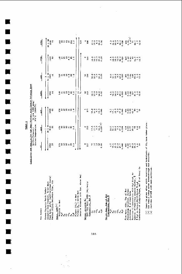
115
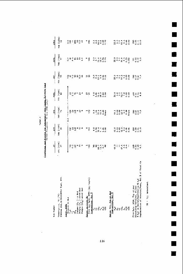
? 0
116
4 m-
I H
I a
a
m m I
I
I
I
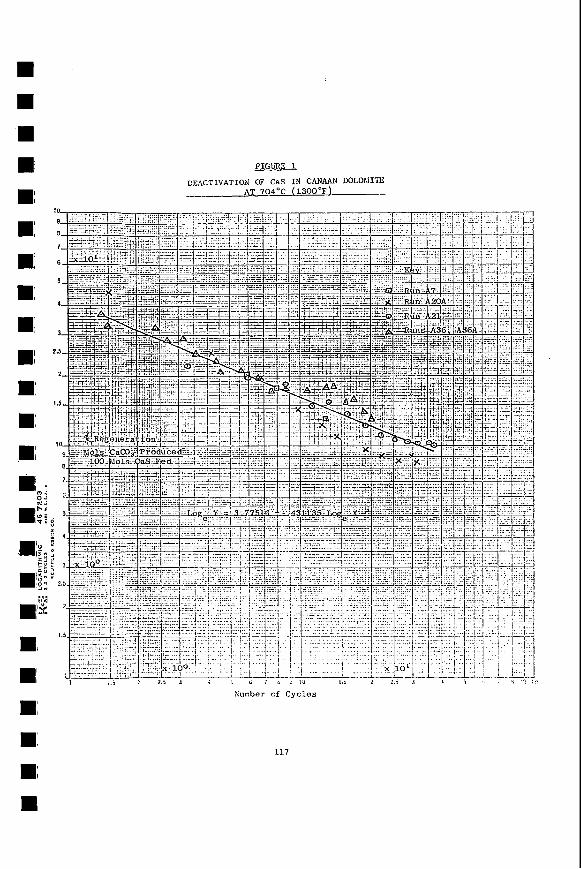
FIGURE 1
DEACTIVATION OF Cas IN CANAAN DOLOhlITE AT 704°C (1300'F)
-I__
Xumber of C y c l c s
117
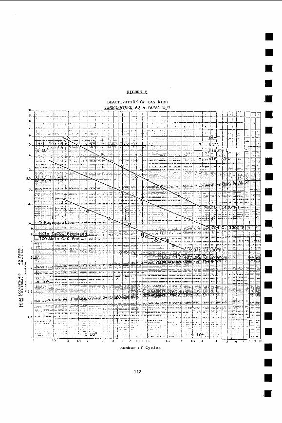
118
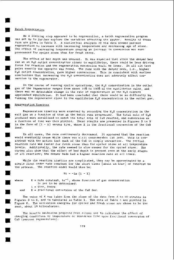
Batch Regenerat ioll
A s a l inl i t ing s t e p appeared t o be r egene ra t ion , a batch r egene ra t ion program was Set U P t o Eurther explore t h e v a r i a b l e s a f f e c t i n g t h e system. Resu l t s of t h e s e runs a r e given i n Table 3. A s t a t i s t i c a l a n a l y s i s of t h e da t a showed pe rcen t r egene ra t ion t o inc rease with inc reas ing temperature and decreasing age of s tone . The e f f e c t of i nc reas ing temperature causing an inc rease i n conversion was more pronounced f o r cycled s tone than f o r f r e s h s t o n e .
The e f f e c t of bed depth was unusual . I t was expected t h a t s ince t h e deeper bed r a n a t an H 2 S o u t l e t concen t r a t ion c l o s e r t o equ i l ib r ium, t h e r e would be l e s s d r i v i n g f o r c e for r eac t ion and the r egene ra t ion conversion would be lower. I n a l l s i x t e s t P a i r s exac t ly t h e oppos i t e was found. HzS o u t l e t concentrat ion, gave h ighe r conversions. This i s cons i s t en t with e a r l i e r conclusions t h a t i nc reas ing t h e H,S concen t r a t ion doos not adversely a f f e c t con- ve r s ion i n the r egene ra to r .
The runs with the deeper beds, i . e . , higher
I n t h e course of running c y c l i c ope ra t ions , t h e H,S concen t r a t ion i n t h e o u t l e t gas of t h e regenerator ranged from about l O $ t o 100% of t h e equi l ibr ium value, and t h e r e was no de tec t ab le change i n t h e r a t e of r egene ra t ion as t he H,S con ten t approached equi l ibr ium. I t had been concluded t h a t t he re would be no d i f f i c u l t y i n running t h e regenerator c l o s e t o t h e equ i l ib r ium H,S concen t r a t ion i n t h e o u t l e t g a s .
Repenerat i on Kine t i c s
Regeneration k i n e t i c s were examined by recording t h e H,S concen t r a t ion i n t h e e x i t gas a s a func t ion of t ime a s the ba t ch runs p rogres sed . The t o t a l mols of H,S produced were normalized t o match t h e t o t a l mols of Cas r e a c t e d , and conversion a s a func t ion of time was then p l o t t e d . These r e s u l t s a r e p re sen ted i n F igu res 3 t o 5 i n the form of (1 - X ) versus t ime, where X is t h e f r a c t i o n a l conversion of t h e CaS feed .
In a l l cases , t h e r a t e cont inuously decreased. I t appeared t h a t t h e r e a c t i o n would eventual ly cease while t h e r e was s t i l l considerable CaS l e f t . Th i s i s con- s i s t e n t with t h e no t ion t h a t much of t h e CaS is simply un reac t ive . The i n i t i a l r e a c t i o n r a t e was f a s t e r f o r f r e s h s tone t h a n f o r cycled s tone a t a l l temperature l e v e l s . Add i t iona l ly , t h e r a t e seemed t o slow sooner f o r t h e cycled s tone . The cu rves a l s o show t h a t t h e e f f e c t of bed depth i s present even a t t h e e a r l y s t a g e s of a l l r eac t ions ; t h e deeper beds had a h ighe r r e a c t i o n r a t e a t a l l t i m e s .
While t he r e a c t i o n k i n e t i c s a r e complicated, they may be approximated by a simple f i r s t order r a t e constant f o r t he sho r t t imes (about an hour) of i n t e r e s t t o t h e p rocess . The r e a c t i o n model would then be:
K t = - In (1 - X )
where K = r a t e cons t an t , hr- i , whose f u n c t i o n of gas concentrat ion
t = time, hours i s yet t o be determined.
and X = f r a c t i o n a l conversion of t h e Cas f e d .
The value of K was taken from t h e s lope of t h e da t a from 5 t o 50 minutes i n F igu res 3 t o 5, and i s t abu la t ed i n Table 4 . The da ta of Table 1 a r e p l o t t e d i n F igu re 6 . The a c t i v a t i o n e n e r g i e s f o r cycled and f r e s h s t o n e a r e shown t o be t h e samc, about 19 k i l o c a l o r i e s .
The b i n c t i c mechanism proposcrl here al.loiirs one t o c x l c u l a t e t h e e f f e c t of changing condi t ions of tenipcrature o r res idence t i n e up011 f r a c t i o n a l conversion of Cas (pe rcen t r egenc ra t ion ) .
119
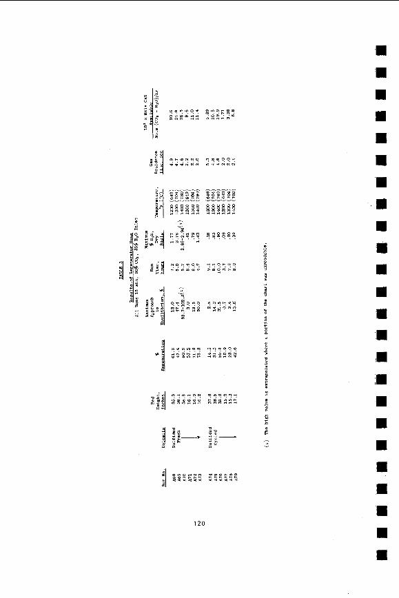
3
9
z
CM Fi
120
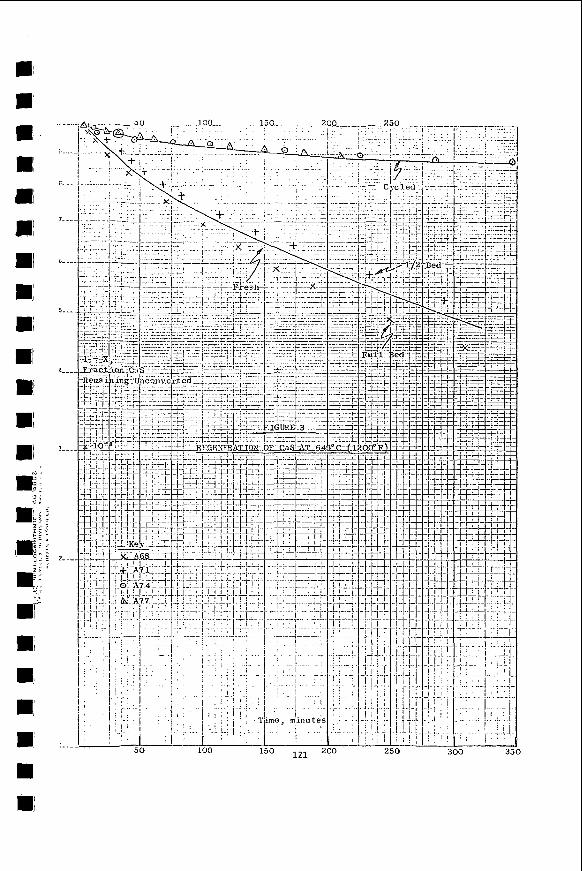
% .. .--w .-.-.loo ............... 150. . 20.0 ! . : . I .%-
. . . . . . . - -. . .... :.. : ! ' :- . , . , .. .!.
.- -. - .... ._
............ ...... __ ....
I 100
. . . . . . . . . ... . . . .
O 121 250 300 3
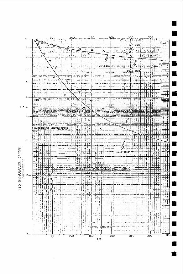
I--
loo-. .- ....... J2.0 . . . . . . . . . . . . I
. I . .
, . . . - . . a .
100 150 200 250 122
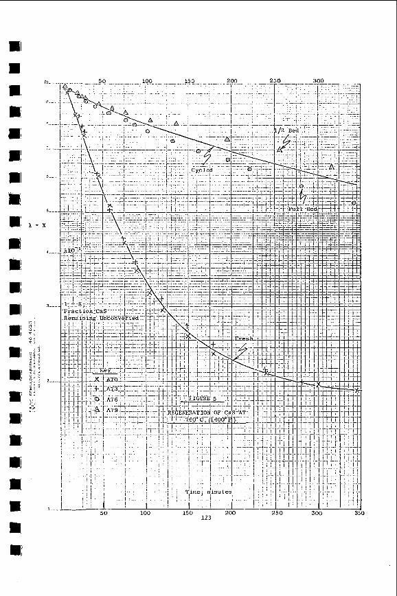
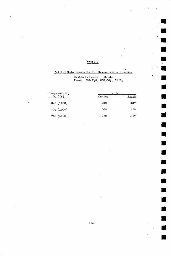
TABLE 4
I n i t i a l Rate Cons tants for Regeneration K i n e t i c s
System Pressure : 15 a t m Feed: 35$ HZO, 60$ C 0 2 , 5‘s H,
Temperature, ‘C ( O F )
649 (1200)
704 (1300)
760 (1400)
1 2 4
k. hr-’ C y c l e d ELEiL
.063 .247
.098 .468
.170 .747
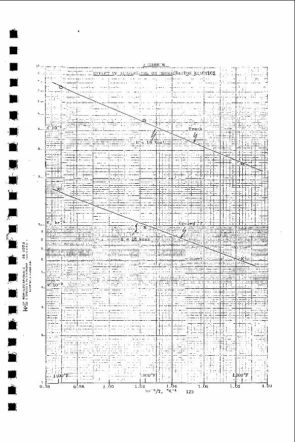
Cycling with Varying Residence Times
Four batcli cyc l ing r u n s were made employing t h e poss ib l e combinations of 20 or 60 minutes r e s idence time f o r s u l f u r abso rp t ion and r egene ra t ion . Resu l t s arc presented i n F igure 7 . Tymochtee 11 doloinite was t h e feeds tock , and each run l a s t e d f o r 11 c y c l e s .
The e f i e c t of reducing r e s idence t i m e i n the gas d e s u l f u r i z e r was s t r i k i n g . A t 10 cyc le s , going from GO t o 20 minutes i n t h e g a s d e s u l f u r i z e r i nc reased r egene ra t ion a c t i v i t y from 15 t o 40% a t 60 minutes regenera tor time and Prom 15 t o 23$ a t 20 minutes r e g e n e r a t o r time. Conversely, go i lx f r o 3 60 t o 20 minutes r egene ra to r t i m e had no e f f e c t a t t h e 60 minute d e s u l f u r i z e r l e v e l . Another e f f e c t observed was t h a t a t t r i t i o n r a t e s were h i g h e s t a t t h e s h o r t gas desu l fu r i ze r res idence t ime, 2.3% average f o r 20 minutes versus 0 . 8 5 f o r 60 minutes .
It is be l i eved t h a t d e a c t i v a t i o n o f s tone t a k e s p lace p r imar i ly i n the gas d e s u l f u r i z e r due t o c r y s t a l growth and p a r t i c l e s i n t e r i n g . This would exp la in the dramat ic e f f e c t of t i m e on a c t i v i t y . The r e s u l t s of t h e above r u n s a r e h igh ly s i g n i f i c a n t s ince t h e y i n d i c a t e t h e p o t e n t i a l f o r g r e a t l y inc reas ing t h e s t o n e ' s capac i ty f o r s u l f u r ab sor p -t i on.
Scannina E lec t ron hlicroscope Data
Se lec t ed samples of cyc led s t o n e were examined under an e l .ec t ron microscope equipped f o r energy d i s p e r s i v e X-ray a n a l y s i s . I t was found t h a t cyc led s tone con- t a i n e d very l a r g e g r a i n s of Cas. The CaCO, which was p re sen t tended t o be concen- t r a t e d i n smal le r s i z e s . Both of t h e calcium s p e c i e s were l a r g e r t h a n t h e MgO c r y s t a l s or g r a i n s . It i s be l i eved t h a t t h e l a r g e r Cas g ra ins a r e un reac t ive i n the regenera t ion s t e p of t h e p r o c e s s .
Model f o r t h e Deac t iva t ion Process
The r egene ra t ion r e a c t i o n s u f f e r s from d e a c t i v a t i o n of t he Cas even from cycle 1. The model pos tu l a t ed below f i t s t h e behavior of t h e system so f a r . The p a r t dea l ing wi th regenera tor v a r i a b l e s was developed j o i n t l y s i t h A. M . Squ i r e s of The C i t y College Clean Fue l s I n s t i t u t e .
Deac t iva t ion of t h e dolomi te occur s mainly i n t h e gas d e s u l f u r i z e r due t o the e l eva ted tempera ture . Two mechanisms are ope ra t ing . C r y s t a l growth of CaCO, and Cas seg rega te s t h e calcium c r y s t a l s from t h e NgO and produces a m a t e r i a l t ending toward a l imes tone r a t h e r t h a n a dolomi te . Simple s i n t e r i n g and d e n s i f i c a t i o n t a k e p lace a s w e l l , and t h i s bo th hardens t h e s tone and t ends t o reduce po ros i ty .
I n t h e r egene ra to r , d e n s i f i c a t i o n does not occur . lionever, t h e r e a c t i o n s t a r t s r a p i d l y and then t a i l s of f t o an i n s i g n i f i c a n t r a t e . Using t h e same feed , it can be shown t h a t t h e convers ion a t whicli r e a c t i o n e s s e n t i a l l ) . c e ~ s e s i s a s t r o n g func t ion of temperature, i h e iower wnipera ture producing t h e io?.ier convers ion . I t has f u r t h e r been observed t h a t i n t roduc ing product H,S docs not r e t a r d t h e r a t e of r eac t ion , b u t converse ly i n c r e a s e s t h e u l t ima te l e v e l of convers ion a t t a i n a b l e .
The phenomenon o f t h e products of r eac t ion inc reas ing ihe convers ion of calcium in t h c su l fur -ca lc ium system is not nev. P e l l ~ found t h a t H,O incrcasctl the convcrsion OE C a O t o CaS i n t h c r e a c t i o n oP 11,s with ca l c ined dolomite, and Ruth(") showed t h a t e i t h e r CO, or II,O c o u l d i nc rease the convers ion 0.l CnCO, t o Cas i n t h e r e a c t i o n of H2S wi th ha l f - ca l c ined clolorni'ic . Furthermore, bo th s t u d i e s demonstrated the e l f e c t 01 t h e r e a c t i o n f laggin:; a t loi-er and lower convcrsiun l e v e l s as tlie r e a c t i o n temperature dcc reased . anism a f t e r exanlination of e l e c t r o n microscupc r e s u l t s 0:: var ious salnpics . l e v e l s ot CO, . . . . niay pi'onmte t h e formiltio:: 01 l a r g e r.~:..;bers of f illc
Rutl:('; proposcd t h e Pollowiu:: nlecIi- "iiigh
126

FIGURE 7
Huns A129 to A 1 3 2 - Deactivation of CaS a t 704OC ( 1 3 0 0 ' F )
127
c r y s t a l l i t e s of Cas t h a t do not p r o t e c t t he underlying CaCO, . . . . On t h e other hand, a t low l e v e l s of CO, a sma l l e r number of l a r g e CaS c r y s t a l s formed and grow toge the r .to c l o s e o f f t h o s u r f a c e , t he reby p r o t e c t i n g t h e remaining CaCO, from f u r t h e r r e a c t i o n ."
Ruth 's c a r e f u l a n a l y s i s of h i s d a t a showed t h a t i n the presence of r e a c t i o n products , t h e r e a c t i o n was indeed s lower i n i t i a l l y . Hov:ever, w i th in a sho r t time t h e conversion a s s o c i a t e d with t h e product-r ich environmenr soon surpassed t h a t i n t h e product-poor environment.
It i s p o s t u l a t e d t h a t a s i m i l a r model f i t s t h e r egene ra t ion r e a c t i o n . A t low l e v e l s of HzS, t h e CaCO, formed grows i n l a r g e c r y s t a l s s h u t t i n g off t h e i n t e r i o r of t h e g r a i n from f u r t h e r r e a c t i o n . A t h igh l e v e l s of H,S, t h e r e a c t i o n nucleates a t many sites t o produce many small c r y s t a l s which leave the i n t e r i o r of t h e g ra in open t o f u r t h e r r e a c t i o n . Via such a mechanism, t h e presence of H,S would enhance conversion i n t h e r e g e n e r a t o r . This is i n f u l l concordance with our experimental r e s u l t s .
Acknowledgment
Appreciat ion i s expressed t o t h e Environmental P r o t e c t i o n Agency for f i n a n c i a l support of t h e work p resen ted i n t h i s paper and f o r permission t o pub l i sh t h e r e s u l t s g iven .
References
1. Curran, G.P., Clancey, J .T . , Pasek, B . , P e l l , A I . , Rutledge, G . D . , and Gorin, E . , "Product ion of Clean Fuel Gas from Bituminous Coals," (1973),
EPA N o . EPA-650/2-73-049, &TIS N o . PB 232-695/AS.
2. Curran, G.P., Koch, B . J . , Pasek, B . , P e l l , > I . , and Gorin, E . , "High Tempera- t u r e Desu l fu r i za t ion of Fue l Gas,'' Report t o EPA under
Contract No. 68-02-1333, i n p repa ra t ion .
3. P e l l , M . , "React ion of Hydrogen S u l f i d e with F u l l y Calcined Dolomite," Ph.D. Thesis , The C i t y Un ive r s i ty of New York (1971) .
4 . Ruth, L . A . , Squ i re s , A . M . , and G r a f f , R . A . , "Desu l fu r i za t ion of F u e l s with Half-Calcined Dolomite: F i r s t K i n e t i c Data," Env. Science @e Tech.,
- 6, 1009-1014, 1972.
5. Ruth, L . A . , "Reaction of Hydrogen Su l f ide a i t h Half-Calcined Dolomite," -. r ~ 1 . E . Thesis , The C i t y Un ivc r s i ty of iiex; York (1972).
128
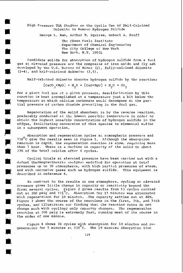
High Pressure TGA Studies on t h e Cycl ic U s e of Half-Calcined Dolomite t o Remove Hydrogen Su l f ide
George L. Kan, Arthur M. Squires , Robert A. Graff
The c lean Fuels I n s t i t u t e Department of Chemical Engineering The c i t y College of New York New York, N.Y. 10031
Candidate s o l i d s f o r absorp t ion of hydrogen s u l f i d e from a f u e l gas a t e levated pressure a r e the composite of i r o n oxide and f l y ash developed by the U.S. Bureau of Mines ( l) , fu l ly-ca lc ined dolomite (2-4), and ha l f -ca lc ined dolomite ( 2 . 5 ) .
Half-calcined dolomite absorbs hydrogen s u l f i d e by the reac t ion :
2 [CaC03+MgO] + H2S = [CaS+MgO] + H 0 + CO
For a given f u e l gas a t a given pressure , desu l fu r i za t ion by t h i s r eac t ion i s b e s t accomplished a t a temperature j u s t a b i t below the temperature a t which calcium carbonate would decompose a t the par- t i a l pressure of carbon dioxide p reva i l i ng i n the f u e l gas.
2
Regeneration of the s o l i d absorbent i s by the reverse r eac t ion , preferab ly conducted a t the lowest poss ib l e temperature i n order t o ob ta in the h ighes t poss ib l e concent ra t ion of hydrogen s u l f i d e i n the o f fgas , f a c i l i t a t i n g conversion of t h i s spec ies t o elemental s u l f u r i n a subsequent opera t ion .
Absorption and regenera t ion cyc les a t atmospheric pressure and 0 750 C g ive the r e s u l t s seen i n Figure 1. Although the absorpt ion
r eac t ion is rap id , the regenerat ion r eac t ion is slow, r equ i r ing more than 1 hour. There i s a dec l ine i n capac i ty of t he s o l i d t o about 23% of the t o t a l calcium a f t e r 6 cyc les .
Cycling t r i a l s a t e leva ted pressure have been c a r r i e d o u t with a duPont therrnogravimetric analyzer modified fo r opera t ion a t t o t a l p ressures up t o 30 atmospheres, wi th high p a r t i a l p ressures of steam, and with cor ros ive gases such a s hydrogen s u l f i d e . This equipment is descr ibed i n re fe rence 6.
I n con t r a s t t o t he r e s u l t s a t one atmosphere, cyc l ing a t e leva ted pressure gives l i t t l e change i n capac i ty o r r e a c t i v i t y beyond the f i r s t severa l cyc les . Figure 2 g ives r e s u l t s from 1 5 cyc les c a r r i e d o u t a t 300 ps ig and 731OC. Absorption f o r 15 minutes was a l t e r n a t e d with regenerat ion f o r 10 minutes. The capac i ty s e t t l e s ou t a t 40%. Figure 3 shows t h e course of t he r eac t ions i n t h e f i r s t , 7th. and 15th cyc les , and i l l u s t r a t e s our f ind ing t h a t t h e r eac t ion r a t e s do not change much with cycling: only capac i ty changes. The regenera t ion r eac t ion a t 300 p s i g i s extremely f a s t , running most of i t s course i n t h e order of one minote.
Figure 4 shows 30 cyc les with absorp t ion f o r 19 minutes and re - 0
generat ion fo r 5 minutes a t 550 C. The 1 9 minutes absorpt ion t i m e
129
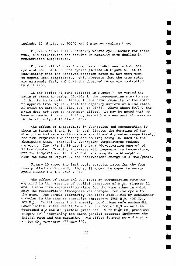
0 includes 13 minutes a t 100 C and 6 minutes cool ing t i m e .
Figure 5 shows s u l f u r capac i ty versus c y c l e number for t h r e e runs, and i l l u s t r a t e s t h e d e c l i n e i n c a p a c i t y with d e c l i n e i n regenerat ion temperature.
Figure 6 i l l u s t r a t e s t h e course of r e a c t i o n s i n t h e l a s t cyc le of each of t h e t h r e e cyc les p l o t t e d i n Figure 5. I t is f a s c i n a t i n g t h a t t h e observed r e a c t i o n r a t e s do n o t seem much t o depend upon temperature. This suggests t h a t t h e t r u e r a t e s are extremely f a s t , and t h a t t h e observed rates are c o n t r o l l e d by d i f fus ion .
In t h e series of runs depic ted i n Figure 7, we v a r i e d t h e r a t i o of stem t o carbon d ioxide i n t h e regenera t ion s t e p t o see i f t h i s i s an important f a c t o r i n the f i n a l capac i ty of t h e s o l i d . I t appears from Figure 7 t h a t t h e capac i ty s u f f e r s a t a l o w r a t i o of steam t o carbon d ioxide , such a s 25/15. Above about 5 0 / 5 0 . t h e r a t i o does n o t s e e m t o have much e f f e c t , I t may be noted t h a t we have succeeded i n a run of 1 5 cycles wi th a steam p a r t i a l p ressure i n t h e v i c i n i t y o f 19 atmospheres.
The e f f e c t o f temperature i n absorp t ion and regenerat ion i s shown in Figures 8 and 9. In both f i g u r e s the dura t ion of t h e absorpt ion and regenera t ion s t e p s a r e 21 and 4 minutes respec t ive ly , t h e t i m e r equi red f o r hea t ing and cool ing being included i n t h e absorpt ion t i m e . Increas ing absorp t ion temperatures reduces capacity. The d a t a i n F igure 8 show a “ d e a c t i v a t i o n energy” of 2 2 kcal/gmole. Capaci ty i n c r e a s e s wi th regenera t ion temperature, b u t the temperature e f f e c t i s not as s t r o n g as i n absorpt ion. From the d a t a of Figure 9, t h e “ a c t i v a t i o n “ energy i s 9 kcal/gmole.
Figure 10 shows t h e l a s t cycle r e a c t i o n r a t e s f o r t h e four runs p l o t t e d i n Figure 8. F igure 11 shows t h e c a p a c i t y versus c y c l e number f o r t h e s a m e runs.
The e f f e c t o f steam and CO l e v e l on regenera t ion rate w a s explored i n t ~ , e presence of p s r ? i a l pressures of H ~ S . Figures 1 2 and 1 3 show f i v e regenera t ion s t e p s f o r t h e same s tone i n which only t h e regenera t ion atmosphere w a s changed from one cyc le t o t h e next. The sample r e a c t i v i t y w a s f i r s t s t a b i l i z e d by conducting 6 cycles i n t h e same regenera t ion atmosphere (50% H20, 40% C 0 2 , 10% H2). Lower i n i t i a l rates r e s u l t from t h e presence of H S a s w e l l as decreased H30 and CO p a r t i a l p ressures . With high CO pressures (Figure 1 2 ) ,- increas ing t h e steam p a r t i a l p ressure increases t h e i n i t i a l ra te and t h e capac i ty . The e f f e c t i s much more dramatic a t l o w C 0 2 pressures (Figure 1 3 ) .
I n a l l cases t h e a s o r p t i o n condi t ions w e r e unchanged.
2 2 2
130
,
The complexities of the kinetic situation illustrated in Figures 12 and 13 are reminiscent of the "kinetic curiosities" reported eariler for the absorption reaction (5) , and like them, the new complexities appear to reflect differences in the way in which crystallites of CaC03 or Cas grow within the solid micro- structure. Examinations or microstructural properties of solids arising in this research will be reported elsewhere (I).
Acknowledqments
This research was supported by the Empire State Electric Energy Research Corporation, Project EP4-3. We thank Richard D. Harvey and his colleagues at the Illinois State Geological Survey for their cooperation.
1.
2.
3 .
4.
5.
6 .
7.
REFERENCES - W.T. Abel, F.G. Schultz, P.F. Langdon, 1 . S . Bureau Mines Rep. Invest. 7947. 1974.
A.M. Squires, Adv. Chem. Ser., vol. 69 (1967), p. 205.
A.M. Squires, R.A. Graff, M. Pell, A.1.Ch.E. Symp. Series, vol. 67, no. 115 (1971), p. 23.
M. Pell, R.A. Graff, A.M. Squires, "Reaction of CaO with H - S " , in Sulfur & SO, Developments, A CEP Technical Manual, p. 151.
1971,L L
L.A. Ruth, R.A. Graff, A.M. Squires, Environmental Sci. & Tech., vol. 6 (1972), p, 1009.
S. Dobner, G. Kan, R.A. Graff, A.M. Squires, Thermochemica Acta. in press.
R.D. Harvey, G. Kan, R.A. Graff, A.M. Squires, "Behavior of Dolomite in Absorption of H S from Fuel Gas", Proceedings of the AIME Fall Meeting, Sept. 1-3, 1976. Denver Colorado. 2
131
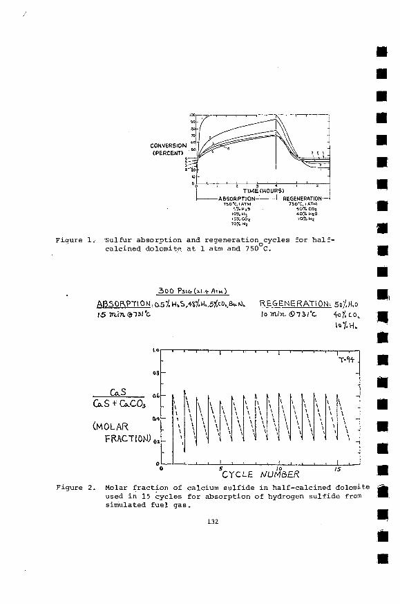
ABSORPTION------CREGENERATION T S O 2 , I A T M 750'C. I ATM
5%U25 50% C02 10% u.2 40% H20
10% Nz 1 5 A C 0 ~ 107. up
Figure 1. S u l f u r absorp t ion and regenera t ion cycles f o r half- 0
ca lc ined dolomite a t 1 atm and 750 C.
Figure 2. Molar f r a c t i o n of calcium s u l f i d e i n ha l f -ca lc ined dolomite used i n 1 5 cyc les f o r absorp t ion of hydrogen s u l f i d e from simulated f u e l gas.
132
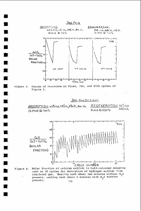
Figure 3 . Course of r e a c t i o n s i n f i r s ' t , 7th. and 1 5 t h cyc les of Figure 2 .
L S L S * L C O 3
(HOLAS -
I O 3s CYCLE IJUM&R
0
Figure 4. Molar f r a c t i o n of calcium s u l f i d e i n ha l f -ca lc ined dolomite used i n 30 c y c l e s f o r absorp t ion o f hydrogen s u l f i d e from simulated gas. p resent , cool ing took about 6 minutes w i t h H S mixture present .
Heating took about two minutes without H2S 2
133
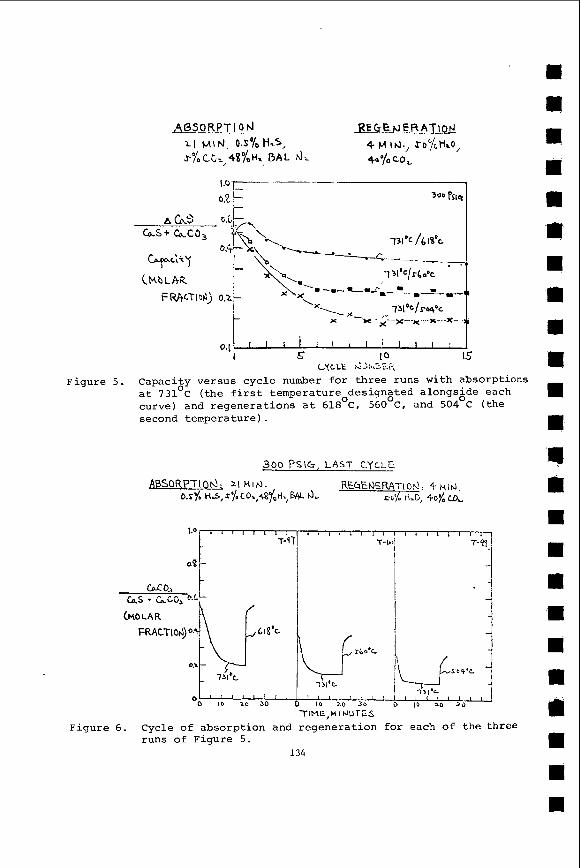
300 PSlG, L A S T CYCLE
l-
TIME,MI r J U T E S
(HOLAR
Figure 6. Cycle of absorption and regeneration f o r each of the three runs of Figure 5.
134
T-I
c: tbo'c
i / i
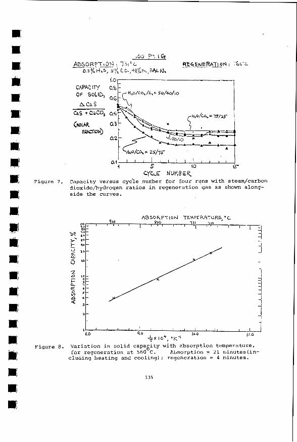
4.0 1 I
0.4
5 10 is- 0.4
4 CYCLE N U M B E K
Figure 7. Capacity versus cyc'le number f o r four runs with steam/carbon dioxidefiydrogen r a t i o s i n regenera t ion gas a s shown along- s i d e the curves.
I " " ! , , , I I , . , , , I Y.0 9.0 Ib.0 I L O
+ x I O + , OK-'
Figure 8. Var ia t ion i n s o l i d capagi ty wi th absorp t ion temperature, f o r regenerat ion a t 560 C . Absorption = 21 minutes( in-
c lua ing lleatiny and coo l ing ) ; regenerat ion = 4 minutes.
135
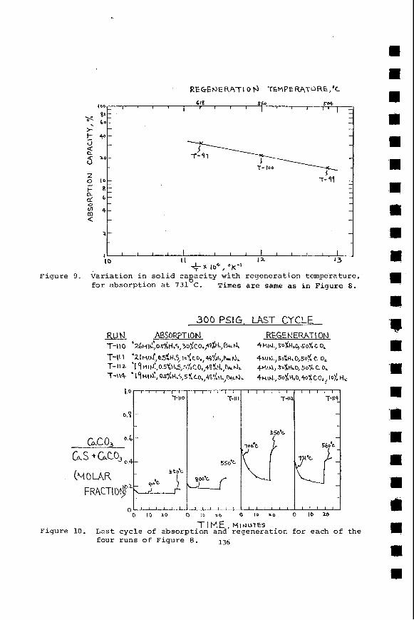
Figure 9.
- 618
I00
80; -s l o -
> - ' - 4 +- 2 9
d -
2 0 I O -
I- 8: a b -
- 2 - $ 4- < -
a -
, l l l l l ~ l ! ~ I , l I ~ IO I I I I - 13
X I O 4 , "k-' Varia t ion i n sol id ca a c i t y with regenerat ion tempe-rature, f o r absorpt ion at 731 C. 8
Times a r e same as i n Figure 8 .
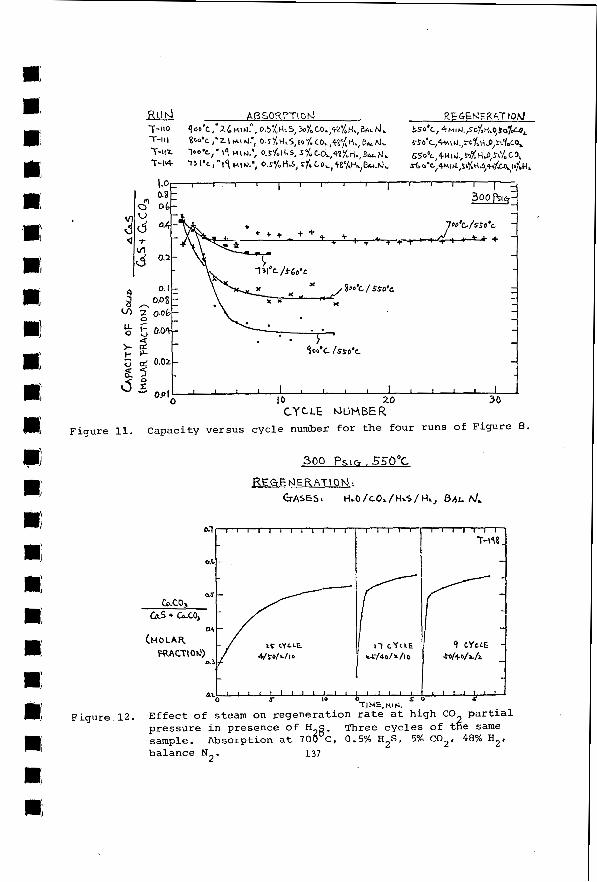
Figure
Figure 12.
s o I O 0 TI HE, Wl r4.
ax ' 1 ' 1 5 ( 1 1 1 1 8 I I 1 I 1 0 1 I I I 1 1 1 1 2
E f f e c t of steam on regenerat ion r a t e a t high CO pressure i n presence o f H sample. Absorption a t 70@;, 0.5% H 2 S . 5% C02, 48% H2,
p a r t i a l Three cyc les of b e same
balance N2. 137
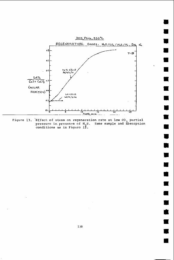
Figure 13. ‘Effect of steam on regenera t ion r a t e a t l o w CO p a r t i a l 2 pressure i n presence o f H S . Same sample and absorpt ion
condi t ions as i n F igure 13.
138