Embed Size (px)
Citation preview
HAL Id: hal-01791837https://hal.univ-lorraine.fr/hal-01791837
Submitted on 14 May 2018
HAL is a multi-disciplinary open accessarchive for the deposit and dissemination of sci-entific research documents, whether they are pub-lished or not. The documents may come fromteaching and research institutions in France orabroad, or from public or private research centers.
L’archive ouverte pluridisciplinaire HAL, estdestinée au dépôt et à la diffusion de documentsscientifiques de niveau recherche, publiés ou non,émanant des établissements d’enseignement et derecherche français ou étrangers, des laboratoirespublics ou privés.
Persistent subplasma-frequency kinetic electrostaticelectron nonlinear waves
T. W. Johnston, Y. Tyshetskiy, A. Ghizzo, Pierre Bertrand
To cite this version:T. W. Johnston, Y. Tyshetskiy, A. Ghizzo, Pierre Bertrand. Persistent subplasma-frequency kineticelectrostatic electron nonlinear waves. Physics of Plasmas, American Institute of Physics, 2009, 16(4), pp.042105. �10.1063/1.3094061�. �hal-01791837�
Persistent subplasma-frequency kinetic electrostatic electron nonlinear wavesT. W. Johnston, Y. Tyshetskiy, A. Ghizzo, and P. Bertrand
Citation: Physics of Plasmas 16, 042105 (2009); doi: 10.1063/1.3094061View online: https://doi.org/10.1063/1.3094061View Table of Contents: http://aip.scitation.org/toc/php/16/4Published by the American Institute of Physics
Articles you may be interested in Electron holes in phase space: What they are and why they matterPhysics of Plasmas 24, 055601 (2017); 10.1063/1.4976854
On the nonlinear trapping nature of undamped, coherent structures in collisionless plasmas and its impact onstabilityPhysics of Plasmas 24, 032109 (2017); 10.1063/1.4978477
On the nature of kinetic electrostatic electron nonlinear (KEEN) wavesPhysics of Plasmas 21, 034501 (2014); 10.1063/1.4868230
Longitudinal Ion Oscillations in a Hot PlasmaThe Physics of Fluids 4, 139 (1961); 10.1063/1.1706174
Undamped electrostatic plasma wavesPhysics of Plasmas 19, 092103 (2012); 10.1063/1.4751440
Hole equilibria in Vlasov–Poisson systems: A challenge to wave theories of ideal plasmasPhysics of Plasmas 7, 4831 (2000); 10.1063/1.1316767
Persistent subplasma-frequency kinetic electrostatic electronnonlinear waves
T. W. Johnston,1 Y. Tyshetskiy,1,2 A. Ghizzo,3 and P. Bertrand3
1INRS-EMT, Varennes, Québec J3X 1S2, Canada2School of Physics, University of Sydney, New South Wales 2006, Australia3LPMIA Université Henri Poincaré, B.P. 239 1-54506 Nancy, cedex France
�Received 2 December 2008; accepted 12 February 2009; published online 10 April 2009�
Driving a one-dimensional collisionless Maxwellian �Vlasov� plasma with a sufficiently stronglongitudinal ponderomotive driver for a sufficiently long time results in a self-sustainingnonsinusoidal wave train with well-trapped electrons even for frequencies well below the plasmafrequency, i.e., in the plasma wave spectral gap. Typical phase velocities of these waves aresomewhat above the electron thermal velocity. This new nonlinear wave is being termed a kineticelectrostatic electron nonlinear �KEEN� wave. The drive duration must exceed the bounce period �B
of the trapped electrons subject to the drive, as calculated from the drive force and the linear plasmaresponse to the drive. For a given wavenumber a wide range of KEEN wave frequencies can bereadily excited. The basic KEEN structure is essentially kinetic, with the trapped electron densityvariation being almost completely shielded by the free electrons, leaving just enough net charge tosupport the wave. © 2009 American Institute of Physics. �DOI: 10.1063/1.3094061�
I. INTRODUCTION
The original trigger for the activity reported here was theremarkable set of results obtained by Montgomery et al.1,2 ina series of laser-plasma interaction experiments. These ex-periments were aimed at improving our knowledge of stimu-lated Raman scattering �SRS� from EPWs from a singlespeckle of laser light and employed laser scattering as a keydiagnostic. In addition to the expected EPW scattering sig-nal, there was also an unexpected signal which was muchsmaller than that associated with SRS-related EPW ��10−3
lower intensity� but nonetheless well out of the noise.The extremely surprising aspect of this scattering result
was that the frequency of the relatively weak electrostaticdensity wave associated with this signal was only a modestfraction ��0.37� of the plasma frequency, which put it rightin the so-called frequency gap where no electrostatic waveought to be, at least according to linear wave theory for aplasma with Maxwellian electrons. The observed wavevectorwas at a modest fraction �0.26� of the reciprocal Debyelength, giving the electrostatic wave a phase velocity not farabove the electron thermal velocity.
As indicated in the papers by Montgomery et al.1,2 andin a related analysis by Rose and Russell,3 waves having thischaracter had been discussed previously in connection within situ observations in the ionosphere and there termedEAWs for electron acoustic waves.4,5 Other analyses onwaves of this kind created by imposition of initial values onthe electron distribution function �but not cited by Montgom-ery et al.� had been published by Schamel6 and by Krapchevand Ram.7 Recently much more light has been shed on thesescattering results1,2 by Strozzi et al.8 who dealt specificallywith the problem of the generation of EAW-style phenom-enon in the presence of strong SRS. �Their work will bediscussed briefly at the end of this paper.�
The theory just cited4–7 and work by many others9–16
�previous to the work by Strozzi et al.8� addressed the prob-lem of the possible persistence of such EAW-style modes butonly when imposed as initial states �with necessarily compli-cated structure in the electron velocity distribution functionnear the phase velocity�. No obvious means exist to imposesuch complicated initial states other than by a simple act ofwill by theorists in a computer model. No discussion wasgiven of how such a state could be generated in a uniformMaxwellian plasma in an actual experiment or in anotherplasma physics event. In view of experimental scattering re-sults of Montgomery et al., the central question of interest ishow a long wave train of electrostatic density modulations�as evidenced by the experimentally observed narrow scat-tering spectrum1,2� but at a frequency far below the plasmafrequency can be obtained via some parametric resonance inspite of the unfavorable low-frequency linear response of aMaxwellian electron velocity distribution. �With no carefullycrafted population of trapped electrons, this response isstrongly damped and broad band.�
To explore the physics of such generation and to makecontact with a possible laboratory experiment using the pon-deromotive force �PF� between two opposing laser beamsappropriately separated in frequency, it was decided �begin-ning in 2001� to undertake a study of the effects of applyinga PF drive to a collisionless uniform Maxwellian plasma inan appropriate computer model for the one-dimensional �1D�electrostatic Vlasov electron plasma. This work was begunby Afeyan at Polymath Research and by Tudor Johnston atINRS-EMT.
In this paper we report the basic, least sophisticated con-cepts distilled from this simulation effort at INRS-EMT. Thesimulations demonstrated successful generation of indefi-nitely self-sustaining low-frequency waves, produced by us-ing a PF drive which �as it turned out� needed to be appliedfor a limited time only. Because these waves are essentially
PHYSICS OF PLASMAS 16, 042105 �2009�
1070-664X/2009/16�4�/042105/15/$25.00 © 2009 American Institute of Physics16, 042105-1
kinetic and electrostatic, because they involve the electrons�with the ions playing a negligible role�, and because theyare, as it proves, essentially nonlinear, it was decided that adistinctive acronym was required to emphasize this. The ac-ronym EAW has been previously used to denote waves in thelinear wave frequency gap between the electron and ionplasma frequencies, with phase velocities not far from theelectron thermal velocity, in contexts ranging from iono-sphere observations, possibly in plasmas with appropriateamounts of clearly defined populations of cold and hotelectrons,4,5 or in plasmas with Landau damping set equal tozero �perhaps because of some special adjustment to theelectron distribution function at some designated phasevelocity�,3,6,7 or as a postulated initial plasma distributionfunction.6,7,9–16 Rather than postulating such distributions,when we drove up the distribution function from the initialMaxwellian by using a limited-time PF driver with a chosenpair of frequency and wavenumbers, we found �as describedbelow� that the trapped electrons obtained kinetically werenot simply a means of negating Landau damping but an es-sential oscillation component quite distinct from and equal ineffect to the rest of the �untrapped� electrons. It also ap-peared that it would be quite difficult to produce such wavesat very low amplitudes, so they should not be confused withthe result of any linear perturbation. The name for this phe-nomenon should properly reflect this essentially nonlinearkinetic behavior. It was decided �at the suggestion of Afeyan�to call them KEEN waves, standing for kinetic electrostaticelectron nonlinear waves. �In a much briefer study at INRS-EMT, to be reported elsewhere, similar aspects were exam-ined with a single species of mobile ions for ionic versions ofthis kind of excitation at frequencies well below the ionplasma frequency. These were �at the suggestion of Afeyan�termed KEIN waves for kinetic electrostatic ion nonlinearwaves.�
The rest of this paper is organized in the following way.It begins with a brief review of previous related work �Sec.II� and of the computer model that was used �Sec. III�. Nextthe basic features of KEEN waves are described in two sub-sections in Sec. IV �basics �A� �Figs. 1–5�, formation dynam-ics �B� �Figs. 6 and 7��. This is followed by Sec. V on thebasic kinetic nature of the KEEN waves, including a com-parison with the initial-value results �Figs. 8 and 9�. In Sec.VI there is a discussion of a phenomenon of what is heretermed “emergent resonance” �Figs. 10–13�. The relationshipof the results presented here to the original purpose of thiswork is then reviewed in Sec. VII, with a final summary andsome closing remarks in Sec. VIII. �The details of the calcu-lation of trapping time under ponderomotive drive are givenin Appendix A, while the details of a particular formulationfor trapped particles are given in Appendix B.�
II. RELATED PREVIOUS WORK
There are three main research themes bearing on theKEEN waves discussed here. The first theme is that of theEAWs,9,10 which arose in ionosphere investigations, their ex-istence being inferred from probe data in the ionosphere.�They are usually seen as requiring two-temperature electron
velocity distributions with considerable difference betweenthe two electron temperatures to allow their existence withweak damping.� The second theme is that of KEEN waves asrealizations of a particular class of the general Bernstein–Greene–Kruskal �BGK� equilibria11 in 1D uniform plasma,in which there might be a wave train with trapped electronssuch that there is no further evolution in some particularframe �the “wave frame”� in which the electron velocity dis-tribution function is stationary. In addition to the work al-ready cited,6,7 one should also consult Schamel’s more recentwork12 �and references cited there�. Some mathematicalrefinements have also been added by Dorning andco-workers.13–16 Lastly there are miscellaneous explorationsof the behavior of 1D phase-space vortices �“holes”� and thelike.17–23 For historical completeness one should also note aparticular laboratory experiment done in a Q-machine result-ing in the creation of a single KEEN-like cell rather than ina long wave train.24
There is also a recent publication by Valentini et al.25
which bears directly on the kind of work presented in thispublication. �While significant aspects of the relation of thatwork to ours will be briefly discussed here in Sec. VI, a fulldiscussion must be deferred for now.�
The work which is reported here was begun by Johnstonat the instigation of Afeyan, and many abstracts on KEENwaves bearing the names of these two individuals have ap-peared in the Bulletin of the American Physical Society from2001 to 2006.26 There is one refereed publication27 in 2004.Also, an Invited Paper at the Division of Plasma Physicsmeeting of 2004 was presented on a KEEN wave experiment�and on other topics�,28 but the full paper was not published.For reasons which need not be discussed here, it was decidedto publish the work performed at INRS-EMT separately fromthe rest, so this paper presents a summary of most of theKEEN wave research which was done at INRS-EMT from2001 to 2006.
III. COMPUTER MODEL
The simplest model containing the basic physics is thatof an electrostatic 1D initially uniform Vlasov plasma in aperiodic box, with the option of an externally imposed pro-grammable ponderomotive drive. �This externally imposedPF approximates that which could be produced experimen-tally by two high-frequency counterpropagating electromag-netic waves.� The parameters of the PF are chosen at will,these parameters being the driving frequency and wavevec-tor, maximum amplitude, and envelope shape as a functionof time �including duration, in particular�. The temporal en-velope of the PF drive consists of two smooth transitionsfrom zero to maximum drive level and back to zero, eachwith a duration Ttrans and a plateau of duration Tplateau inbetween. While the PF does not directly involve the Poissonequation, its effects on the electron density will necessarilygive rise to an electrostatic response mediated by the Poissonequation. In this work the effect of ion motion is generallyneglected, although it can easily be added. �As remarkedabove, ion motion is a necessary part of the KEIN wavephenomena mentioned above, and these are to be reported
042105-2 Johnston et al. Phys. Plasmas 16, 042105 �2009�
elsewhere.� The normalization of units is the conventionalchoice for an electrostatic Vlasov electron plasma with aninitial Maxwellian velocity distribution of �f �exp�−v2 /2vTe
2 ��. �The thermal velocity is as usual related to the elec-tron temperature via vTe= ��BT /m�1/2.� The natural computa-tional units are thus V=v /vTe for velocity, T=�pt for time�with plasma frequency �p= �ne2 /�0m�1/2�, X=x /�D forspace �with respect to the Debye length �D�=vTe /�p��, andeE / �m�pvTe� and Fp / �m�pvTe� for electric and PFs, respec-tively �here E is the electric field, Fp is the PF�.
In order to be able to resolve fine details of the electrondistribution function evolution we use a simulation periodicbox which is precisely only two driver wavelengths long �sothat a full wavelength is always seen in the simulation re-gion�. This of course means that the spatial aspects of pos-sible behavior equivalent to the spatially modulational insta-bility of electron plasma �Langmuir� waves are suppressed insuch short simulations �because relatively close wavenum-bers associated with spatial modulation require relativelylong simulation domains�, although temporal modulation isallowed.
With the aim of obtaining the finest detail of the velocitydistribution function, rather than using the commonly usedparticle-in-cell �PIC� model for the Vlasov plasma with itsinevitable noise, we used the simplest �1D, electrostatic, pe-riodic, with nonrelativistic electrons and stationary ions� Eu-lerian Vlasov fluid �EVF� model as developed initially byCheng and Knorr29 and as further developed by Bertrand andGhizzo et al.30 For those not familiar with EVF codes for 1Dplasmas, we note that the computational burdens for the PICand Vlasov fluid codes are comparable and fine structures inthe �x ,v� phase space are easily resolved by the latter, with-out the complications of discrete particle “noise”, providedthe velocity resolution is sufficiently good. In the 1D EVFmodel, although noise and precision are not severe limits, thevelocity resolution requirement near the phase velocity of thewave for very small traveling-wave perturbations can imposea severe computation burden. This large burden for smallperturbations is chiefly due to the fact that the fine velocityresolution, although really required only near the wave phasevelocity, is actually imposed over all velocity space, sincevelocity mesh with current algorithms is required to be uni-form over velocity space. Also for weak drives much longersimulation times are required. Hence, although initial signalscan be very small in principle, one prefers not to make themmuch smaller than necessary to access the desired physics.�In passing, while EVF can also be done in principle for twovelocity dimensions, the computational burden relative toPIC codes increases dramatically because much effort is ex-pended in calculating the velocity distribution density func-tion in regions of velocity space where the density is verylow.�
Because we wished to be able to take spatial Fouriertransforms easily, we chose to have 512 space mesh points inour space box which was chosen to be exactly two KEENwavelengths long. �For a typical KEEN wave value of 0.26for k�D, this meant that our space mesh step was thus typi-cally 0.0944�D.� The time step was usually chosen to be 0.04in plasma radian frequency units, so for a typical plasma-
normalized KEEN frequency value of 0.37, the time step wasroughly 1/425 of this KEEN period, allowing excellent rep-resentation of the highest harmonics of interest. Finally, inVlasov fluid codes the velocity mesh is also specified, andwe chose 1025 velocity mesh points over the range from−6vTe to +6vTe, where vTe is the electron thermal velocity ofthe initial Maxwellian plasma, for a velocity interval �v of�6 /512�vTe=0.01172vTe.
Because of the low-noise properties of the EVF modelsome useful diagnostics are readily available which are notsuitable for most PIC code systems. For a particular signal, ifthe frequency spectrum �or a selected portion of it� proves tobe dominated by a single slowly varying frequency compo-nent, one can obtain at any time the amplitude of the signalenvelope and the instantaneous signal phase �and hence theinstantaneous frequency� by using the time quadrature sig-nal. If only a real time signal �say, from a probe� is available,one can readily generate the required time quadrature com-ponent using the Hilbert transform �usually via fast Fouriertransform �FFT� in time�.31 The signal envelope and signalphase are obtained, respectively, as the square root of thesum of the squares of the real signal and the quadrature sig-nal and as the arctangent of the ratio of the real and quadra-ture signals �provided one arranges for phase continuity asthe branch cuts of the arctangent function are encountered�.Often one can readily obtain equivalent information fromvarious spatial Fourier transform components with real andimaginary components for which the phase behavior is usu-ally ignored. In this work when we show a frequency it is thefrequency of the fundamental spatial Fourier component ofthe electron charge density, which is available in complexform �real and imaginary components� at each time step andwhich could be imagined to be available in a scattering di-agnostic in an experiment. This frequency is obtained via�n= ��n+1−�n−1� / �2�tstep�, where �n is the phase at the nthtime step of the fundamental spatial Fourier component ofthe electron charge density.
IV. BASIC KEEN WAVE FEATURES
A. KEEN formation dynamics
For linear waves which are not unstable �and which thusdo not tend to grow without limit�, the canonical behavior fordrive times which are long compared to the decay time�wave decay for the � and k values of interest here is veryshort� is that, when the drive is turned off, the level of thedriven waves is proportional to the drive strength, andchanging the drive duration does not affect that. However,for the waves of interest here the behavior is quite different.It turns out that, if the PF drive is of sufficient level and isapplied long enough, it produces a KEEN wave with distinc-tively nonsinusoidal waveform, and this wave then persistsfor very long time after the drive has been turned off, farlonger than the linear decay time, as if the linear �Landau�damping has been destroyed. This striking longevity of theKEEN waves is clearly remarkable and has led to a study ofthe drive threshold above which the persistent KEEN wavesare produced. We found empirically that, for any particulartime program �i.e., particular values of Ttrans and Tplateau� we
042105-3 Persistent subplasma-frequency… Phys. Plasmas 16, 042105 �2009�
used for the PF drive, there is a rough threshold for the PFdrive strength, above which KEEN wave can be producedreadily and below which no enduring KEEN wave wouldresult. Conversely, for a given PF drive strength, a suffi-ciently long PF drive envelope effective duration Teff is re-quired for producing a self-sustaining KEEN wave �here wedefine the effective drive duration as Teff=Tplateau+Ttrans,which is the effective time during which the drive is at itsmaximum�.
The available simulation results suggest that a criterionof necessary drive strength and duration for producing a sur-viving KEEN wave can be established in terms of the char-acteristic electron bounce �or trapping� time �B relevant tothe formation of an electron trapping vortex in �X ,V� phasespace. When electron trapping is discussed, usually onlyelectrostatic electric fields are involved. In calculating theelectron bounce �trapping� time �B when both ponderomotivedrive and the induced electrostatic field coexist, as here, oneneeds to obtain the result including the dynamics of coexist-ence in a self-consistent way. A reasonable concept is toestimate the response of the untrapped particles using lineartheory. It turns out that the electron plasma response for un-trapped electrons proves to be well approximated by lineartheory over a sufficiently long �up to �B /2� time during thedrive. The resulting normalized electron bounce �or trapping�time �B�p in the plasma is obtained �see Appendix A� as�B�p=2��p /�B=2���1+e� /k�Da�1/2, where a is the nor-malized �dimensionless� ponderomotive drive amplitudeand e�� /�p ,k�D� is the electron susceptibility. The factor1+e is a large correction at the low frequencies for the caseat hand. The plasma response is essentially that of animperfect but fairly effective shield. For our usual param-eters � /�p=0.37, k�D=0.26 we have e=−1.21+9.59i, andthe normalized trapping time is then �B�p
=2��9.6 / �0.26a��1/2=38.2a−1/2. This is the formula used toindicate �B in Figs. 1–3 �and later for Figs. 6 and 7�.
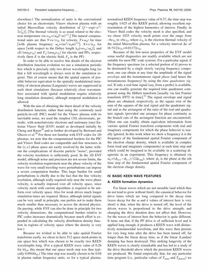
First, in Fig. 1, one has a typical subthreshold resultwhen the drive is evidently unsuccessful in producing a long-lived KEEN wave. The trapping period �B �as indicated bythe length of the double-headed arrow labeled �B in Fig. 1,between the EF �electrostatic force� and PF �ponderomotiveforce� frames� for the net force during the drive is in this caseconsiderably greater than the effective drive duration �abouttwice� and the drive is ineffective. For unsuccessful drivecases like this, after the drive is switched off, the electrostaticfield in the plasma becomes far less than the value inducedduring the drive, being rather comparable to the net forceduring the drive, and decreases in an irregular manner. Notealso that during the drive period, as predicted from the linearresponse theory, the net force acting on electrons �EF+PF� isfar less than either the drive or the resultant electrostaticforce EF, which in fact acts mostly to cancel the ponderomo-tive drive. To produce a KEEN wave one would have todrive harder or longer or both.
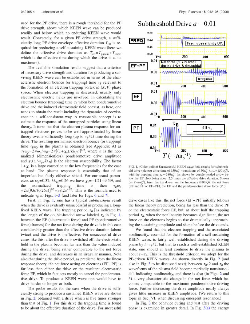
The probe results for the case when the drive is suffi-ciently strong to produce a sustained KEEN wave are shownin Fig. 2, obtained with a drive which is five times strongerthan that of Fig. 1. For this drive the trapping time is foundto be about the effective duration of the drive. For successful
drive cases like this, the net force �EF+PF� initially followsthe linear theory prediction, being far less than the drive PFor the electrostatic force EF, but, at about half the trappingperiod �B, when the nonlinearity becomes significant, the netforce on the electrons begins to rise dramatically, approach-ing the sustaining amplitude and shape before the drive ends.
We found that the electron trapping and the associatednonlinearity, essential for the formation of a self-sustainingKEEN wave, is fairly well established during the drivingphase by t=�B /2, but that to reach a well-established KEENstate, one should at least continue to drive the plasma toabout t=�B. This is the threshold criterion we adopt for thePF-driven KEEN waves. As shown directly in Fig. 2 �andalso in Fig. 3 to be discussed next�, between �B /2 and �B thewaveforms of the plasma field become markedly nonsinusoi-dal, indicating nonlinearity, and there is also �in Figs. 2 and3� a very characteristic change in the net force which be-comes comparable to the maximum ponderomotive drivingforce. Further increasing the drive amplitude nearly alwaysgives little increase in KEEN amplitude. �We return to thistopic in Sec. VI, when discussing emergent resonance.�
In Fig. 3 the behavior during and just after the drivingphase is examined in greater detail. In Fig. 3�a� the energy
FIG. 1. �Color online� Unsuccessful KEEN wave field results for subthresh-old drive �plateau drive time of 150�p
−1 �transitions of 50�p−1�, tFP=150�p
−1�,with the trapping time �B�380�p
−1 �as shown by double-headed arrow be-low the EF plot� being about 2.5 times the effective drive duration. Shown�vs T= t�p
−1�, from the top down, are the frequency �FREQ�, the net force�EF and PF or EF+PF�, the EF, and the ponderomotive drive force �PF�.
042105-4 Johnston et al. Phys. Plasmas 16, 042105 �2009�
absorbed in the system is shown to grow linearly with timeduring the first part of the drive up to �B /2, at a rate which isgiven by the linear susceptibility calculation �power in= �PF / �1+e��2Im�e� /2��. After that, i.e., between �B /2 and�B, the absorbed energy grows noticeably faster than the lin-ear rate, presumably due to additional energy delivery totrapped particles. During this time the high spatial harmonicsof the plasma charge density become very noticeable, asshown in Fig. 3�b�, as the KEEN’s net force nonsinusoidalwaveform is set up, as seen in Fig. 3�c�. This change seemsessential to the transition to a free-running KEEN wave. Ifone examines Fig. 3�c� with care, the last rather rapid changein the net force waveform is associated with a phase dis-placement of the electric field which begins to be delayedand to approach the ponderomotive peak. This producesmuch larger but more highly localized peaks in total field,leading to the formation of the highly nonsinusoidal KEENstructures.
B. Basic KEEN waveforms
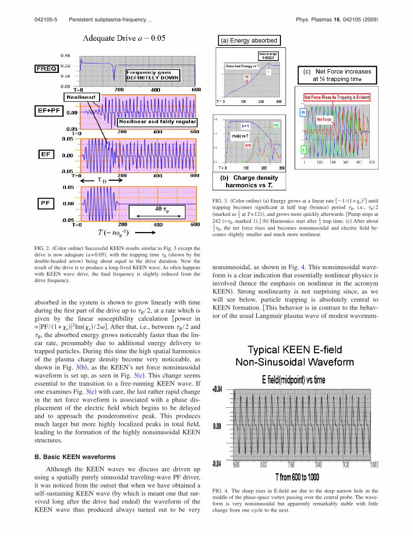
Although the KEEN waves we discuss are driven upusing a spatially purely sinusoidal traveling-wave PF driver,it was noticed from the outset that when we have obtained aself-sustaining KEEN wave �by which is meant one that sur-vived long after the drive had ended� the waveform of theKEEN wave thus produced always turned out to be very
nonsinusoidal, as shown in Fig. 4. This nonsinusoidal wave-form is a clear indication that essentially nonlinear physics isinvolved �hence the emphasis on nonlinear in the acronymKEEN�. Strong nonlinearity is not surprising since, as wewill see below, particle trapping is absolutely central toKEEN formation. �This behavior is in contrast to the behav-ior of the usual Langmuir plasma wave of modest wavenum-
FIG. 2. �Color online� Successful KEEN results similar to Fig. 3 except thedrive is now adequate �a=0.05�, with the trapping time �B �shown by thedouble-headed arrow� being about equal to the drive duration. Now theresult of the drive is to produce a long-lived KEEN wave. As often happenswith KEEN wave drive, the final frequency is slightly reduced from thedrive frequency.
FIG. 3. �Color online� �a� Energy grows at a linear rate ��1 / �1+e�2� untiltrapping becomes significant at half trap �bounce� period �B, i.e., �B /2�marked as 1
2 at T=121�, and grows more quickly afterwards. �Pump stops at242 �=�B, marked 1�.� �b� Harmonics start after 1
2 trap time. �c� After about12�B, the net force rises and becomes nonsinusoidal and electric field be-comes slightly smaller and much more nonlinear.
FIG. 4. The sharp rises in E-field are due to the deep narrow hole in themiddle of the phase-space vortex passing over the central probe. The wave-form is very nonsinusoidal but apparently remarkably stable with littlechange from one cycle to the next.
042105-5 Persistent subplasma-frequency… Phys. Plasmas 16, 042105 �2009�
ber �k2�D2 1�, which can exist at very low amplitudes with
little trapping and with quite sinusoidal waveforms even atsignificant strength.�
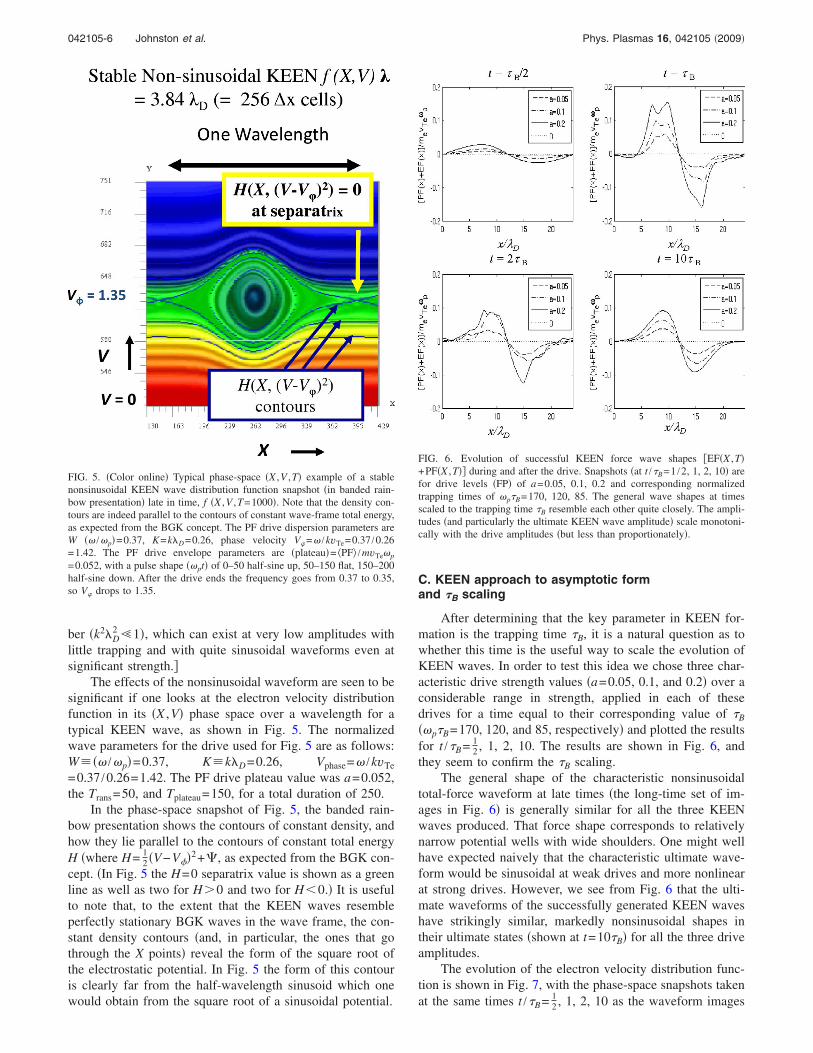
The effects of the nonsinusoidal waveform are seen to besignificant if one looks at the electron velocity distributionfunction in its �X ,V� phase space over a wavelength for atypical KEEN wave, as shown in Fig. 5. The normalizedwave parameters for the drive used for Fig. 5 are as follows:W��� /�p�=0.37, K�k�D=0.26, Vphase=� /kvTe
=0.37 /0.26=1.42. The PF drive plateau value was a=0.052,the Trans=50, and Tplateau=150, for a total duration of 250.
In the phase-space snapshot of Fig. 5, the banded rain-bow presentation shows the contours of constant density, andhow they lie parallel to the contours of constant total energyH �where H= 1
2 �V−V��2+�, as expected from the BGK con-cept. �In Fig. 5 the H=0 separatrix value is shown as a greenline as well as two for H�0 and two for H 0.� It is usefulto note that, to the extent that the KEEN waves resembleperfectly stationary BGK waves in the wave frame, the con-stant density contours �and, in particular, the ones that gothrough the X points� reveal the form of the square root ofthe electrostatic potential. In Fig. 5 the form of this contouris clearly far from the half-wavelength sinusoid which onewould obtain from the square root of a sinusoidal potential.
C. KEEN approach to asymptotic formand �B scaling
After determining that the key parameter in KEEN for-mation is the trapping time �B, it is a natural question as towhether this time is the useful way to scale the evolution ofKEEN waves. In order to test this idea we chose three char-acteristic drive strength values �a=0.05, 0.1, and 0.2� over aconsiderable range in strength, applied in each of thesedrives for a time equal to their corresponding value of �B
��p�B=170, 120, and 85, respectively� and plotted the resultsfor t /�B= 1
2 , 1, 2, 10. The results are shown in Fig. 6, andthey seem to confirm the �B scaling.
The general shape of the characteristic nonsinusoidaltotal-force waveform at late times �the long-time set of im-ages in Fig. 6� is generally similar for all the three KEENwaves produced. That force shape corresponds to relativelynarrow potential wells with wide shoulders. One might wellhave expected naively that the characteristic ultimate wave-form would be sinusoidal at weak drives and more nonlinearat strong drives. However, we see from Fig. 6 that the ulti-mate waveforms of the successfully generated KEEN waveshave strikingly similar, markedly nonsinusoidal shapes intheir ultimate states �shown at t=10�B� for all the three driveamplitudes.
The evolution of the electron velocity distribution func-tion is shown in Fig. 7, with the phase-space snapshots takenat the same times t /�B= 1
2 , 1, 2, 10 as the waveform images
FIG. 5. �Color online� Typical phase-space �X ,V ,T� example of a stablenonsinusoidal KEEN wave distribution function snapshot �in banded rain-bow presentation� late in time, f �X ,V ,T=1000�. Note that the density con-tours are indeed parallel to the contours of constant wave-frame total energy,as expected from the BGK concept. The PF drive dispersion parameters areW �� /�p�=0.37, K=k�D=0.26, phase velocity V�=� /kvTe=0.37 /0.26=1.42. The PF drive envelope parameters are �plateau�= PF /mvTe�p
=0.052, with a pulse shape ��pt� of 0–50 half-sine up, 50–150 flat, 150–200half-sine down. After the drive ends the frequency goes from 0.37 to 0.35,so V� drops to 1.35.
FIG. 6. Evolution of successful KEEN force wave shapes �EF�X ,T�+PF�X ,T�� during and after the drive. Snapshots �at t /�B=1 /2, 1, 2, 10� arefor drive levels �FP� of a=0.05, 0.1, 0.2 and corresponding normalizedtrapping times of �p�B=170, 120, 85. The general wave shapes at timesscaled to the trapping time �B resemble each other quite closely. The ampli-tudes �and particularly the ultimate KEEN wave amplitude� scale monotoni-cally with the drive amplitudes �but less than proportionately�.
042105-6 Johnston et al. Phys. Plasmas 16, 042105 �2009�
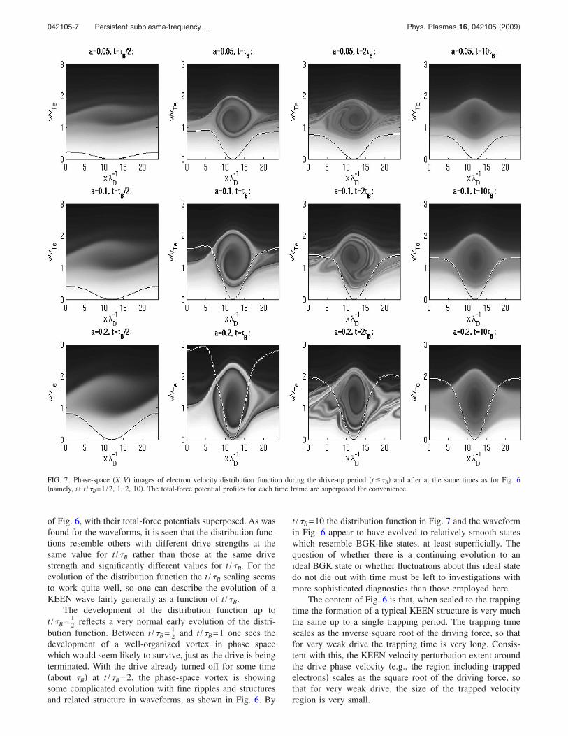
of Fig. 6, with their total-force potentials superposed. As wasfound for the waveforms, it is seen that the distribution func-tions resemble others with different drive strengths at thesame value for t /�B rather than those at the same drivestrength and significantly different values for t /�B. For theevolution of the distribution function the t /�B scaling seemsto work quite well, so one can describe the evolution of aKEEN wave fairly generally as a function of t /�B.
The development of the distribution function up tot /�B= 1
2 reflects a very normal early evolution of the distri-bution function. Between t /�B= 1
2 and t /�B=1 one sees thedevelopment of a well-organized vortex in phase spacewhich would seem likely to survive, just as the drive is beingterminated. With the drive already turned off for some time�about �B� at t /�B=2, the phase-space vortex is showingsome complicated evolution with fine ripples and structuresand related structure in waveforms, as shown in Fig. 6. By
t /�B=10 the distribution function in Fig. 7 and the waveformin Fig. 6 appear to have evolved to relatively smooth stateswhich resemble BGK-like states, at least superficially. Thequestion of whether there is a continuing evolution to anideal BGK state or whether fluctuations about this ideal statedo not die out with time must be left to investigations withmore sophisticated diagnostics than those employed here.
The content of Fig. 6 is that, when scaled to the trappingtime the formation of a typical KEEN structure is very muchthe same up to a single trapping period. The trapping timescales as the inverse square root of the driving force, so thatfor very weak drive the trapping time is very long. Consis-tent with this, the KEEN velocity perturbation extent aroundthe drive phase velocity �e.g., the region including trappedelectrons� scales as the square root of the driving force, sothat for very weak drive, the size of the trapped velocityregion is very small.
FIG. 7. Phase-space �X ,V� images of electron velocity distribution function during the drive-up period �t��B� and after at the same times as for Fig. 6�namely, at t /�B=1 /2, 1, 2, 10�. The total-force potential profiles for each time frame are superposed for convenience.
042105-7 Persistent subplasma-frequency… Phys. Plasmas 16, 042105 �2009�
The behavior after a trapping period has not yet beenexamined in detail, but what happens to a driven KEENwave after the trapping period has been reached can be out-lined as follows. Usually, if the drive is extended beyond theelectron trapping period �B, the amplitude of the wave beingdriven begins to oscillate on the scale of the trapping period,starting with a decrease to a lower value �usually down to80% or so� and then back up again to the original maximumvalue attained at Tdrive=�B. Driving past one �B does notincrease the maximum amplitude of the resulting KEENwave. Turning off the drive in a time short compared withthe electron trapping period �but after a duration long com-pared with a trapping period� leaves the KEEN wave ampli-tude at about its value when turn-off was initiated. Whatappears to be happening is that a phase mismatch betweenthe PF drive and the plasma response develops over time dueto nonlinear effects and energy is subsequently exchanged inoscillatory fashion �with period of the order of �B� betweenthe driver and the KEEN wave without steady accumulationin the latter, and this exchange ceases when the drive is ter-minated. The ultimate amplitude of the KEEN wave is de-fined by the phase in this oscillatory energy exchange atwhich the drive has been turned off. However, although itwas not realized when this behavior was being studied by usearlier, in exceptional cases continuing energy accumulationby the KEEN wave can occur and this is discussed inSec. VI.
V. KINETIC NATURE OF KEEN WAVES
The evidence has been presented that a fairly steadystate in the wave frame can indeed be obtained by applying aprescribed ponderomotive driver for a limited time. It is timenow to turn to some diagnostics which indicate how, so tospeak, the KEEN wave maintains its equilibrium. For thisaspect, as well as investigating the KEEN waves driven upponderomotively, it was judged appropriate to include insuch analysis some examples of KEEN waves obtained inthe same way used in nearly all the previous work. There oneseeks to obtain some approximation to an ideal state for asteady wave with trapped particles, where the system appearsperfectly still in the frame traveling at the wave speed, inwhat is normally known as a BGK state.11 This commonmethod was simply to begin by setting up by some BGKanalytic prescription for the velocity distribution in phasespace, as an approximation to the desired final state and seeif this state survived.3,7,12–18
In order to be able to respond to comments related to theconstructive or initial-value method, it was examined insome detail, of which only the most essential points aregiven in this paper. One should recall that the BGK concept,when reduced to its essentials, is the assertion that, for steadystate behavior in the wave frame, the distribution function inthat frame should be a function of space only implicitly, i.e.,through the behavior of any space-varying potential in rel-evant canonical particle conserved quantities. In the 1D elec-trostatic case of interest here this means that the distributionfunction must be a function only of the particle total energy�from which the velocity may be calculated when the elec-
trostatic potential is given�. �It is often not appreciated thatBGK �Ref. 11� did not assert anything about whether BGKmodes actually exist and whether they are stable in a particu-lar velocity frame. The assertion was only that if such sta-tionary solutions exist, then they must follow the BGK rule.One should therefore always test such a BGK candidate forstability with a proper simulation, to see that it will endureclose to the original formulation.�
What we have found is that, as shown in Fig. 5, electrondistribution density contours in phase space seem to followquite closely the contours of the total particle energy, as theyshould in a BGK equilibrium. On closer examination, how-ever, deviations from this ideal are seen which are not sta-tionary in the wave frame and whose ultimate fate is uncer-tain. Hence in this work, at least, the BGK model is regardedas an extraordinarily useful ideal which is probably very dif-ficult to attain, rather than as an attractive state to which thesystem evolves.
When choosing an initial distribution function accordingto the BGK canon, one has considerable freedom to choosethe details. Naturally, for a given potential the distributionresults of the different functional recipe choices for trappedparticles will differ from each other. After considering theexplicit recipes given by Holloway and Dorning �Ref. 14, inEq. �84�� and by Eliasson and Shukla �Ref. 32, in Eq. �9��,they were not used here because those recipes tended to givedistribution function velocity wells whose depths were muchshallower �for the same well velocity widths� than those seenfor PF-driven KEEN waves. The distribution function formthat was adopted here was a significant modification of alittle-known form given by Allis.33 This modification wasnecessary to avoid unphysical discontinuities in the result�see Appendix B�, and this modified form was hence dubbedthe Allis–Johnston �AJ� formula. This recipe was developedin a very organic way from a Maxwellian, with which ourdrive program began, and, most gratifyingly, the velocity dis-tribution function was found to agree quite well with KEENvelocity distributions for the same potential, as shown in Fig.8 for the deepest part of the potential well in a typical case.
In the top row of Fig. 9 are shown a typical drivenKEEN wave �on the right� with an equivalent AJ result �onthe left� for the same maximum potential but using a sinu-soidal assumption �almost invariably used in BGK work� forthe initial potential waveform. While the section across themaximally perturbed region may look the same �as shown inFig. 8�, the AJ construction begun with a sinusoid usuallyremains superficially sinusoidal and so the separatrix looksrather like half-wavelength sinusoid. �However, the netcharge waveform, which is proportional to the second spatialderivative of the potential, is distinctly nonsinusoidal, resem-bling a cnoidal waveform rather than a sinusoid.� In contrastto this, the KEEN wave driven up from a sinusoidal driverhas here been shown to be much more nonsinusoidal. Thus,while constructing BGK moving equilibria using a suitablerecipe may give something resembling a KEEN driven up inspecific way, the actual waveforms will not correspond wellunless the initial waveform used for initiating a BGK-likestate is copied from an actual driven KEEN result.
In the bottom row of Fig. 9 are plotted the spatial varia-
042105-8 Johnston et al. Phys. Plasmas 16, 042105 �2009�
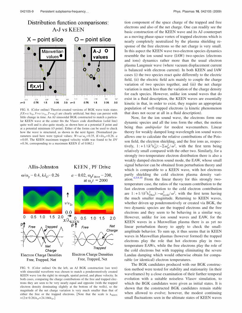
tion component of the space charge of the trapped and freeelectrons and also of the net charge. One can readily see thebasic construction of the KEEN wave and its AJ counterpartas a moving phase-space vortex of trapped electrons which isnearly completely neutralized by the plasma shielding re-sponse of the free electrons so the net charge is very small.In this aspect the KEEN wave two-electron species dynamicsresemble the ion sound wave �IAW� two-species �electronsand ions� dynamics rather more than the usual electronplasma Langmuir wave �where vacuum displacement currentis balanced with electron current�. In both KEEN and IAWcases �i� the two species react quite differently to the electricfield, �ii� the electric field acts mainly to couple the chargevariation of two species together, and �iii� the net chargevariation is much less than the variation of the charge densityfor each species. However, unlike ion sound waves that doexist in a fluid description, the KEEN waves are essentiallykinetic in that, in order to exist, they require an appropriatepopulation of well-trapped electrons �a kinetic phenomenonthat does not occur at all in a fluid description�.
Now, for the ion sound wave, the electrons form onedynamic species and all the ions form the other, the motionbeing thus ambipolar for modest wavenumbers. Lineartheory for weakly damped long-wavelength ion sound wavesallows one to calculate the relative contributions of the Pois-son field, the electron shielding, and the free ions as, respec-tively, 1 : +1 / �k2�D
2 � :−��pi2 /�2, with the first term being
relatively small compared with the other two. Similarly, for astrongly two-temperature electron distribution there is also aweakly damped electron sound mode, the EAW, whose smallsignal behavior can be obtained from perturbation theory andwhich is comparable to a KEEN wave, with hot electronspartly shielding the cold electron plasma density vari-ation.4,5,9,10 From the linear theory for this strongly two-temperature case, the ratios of the vacuum contribution to thefast electron contribution to the cold electron contributionare 1: +1 / �k2�Dhot
2 � :−�pcold2 /�2, with the first term having
the much smaller magnitude. Returning to KEEN waves,whether driven up ponderomotively or created via BGK, thetwo dynamic species are the trapped electrons and the freeelectrons and they seem to be behaving in a similar way.However, unlike for ion sound waves and EAW, for theKEEN waves in a Maxwellian plasma there is as yet nolinear perturbation theory to apply to check the small-amplitude behavior. To sum up, it thus seems that in KEENwaves in Maxwellian plasmas �however formed� the trappedelectrons play the role that hot electrons play in two-temperature EAWs, while the free electrons play the role ofthe cold electrons but with trapping eliminating the severeLandau damping which would otherwise obtain for compa-rable �or identical� electron temperatures.
The BGK candidates produced with our BGK construc-tion method were tested for stability and stationarity �in theirwaveframes� by a close examination of their further temporalevolution with a suitable noiseless Vlasov simulation, towhich the BGK candidates were given as initial states. It isshown that the constructed BGK candidates remain stablewhen allowed to evolve; however, the modest continuingsmall fluctuations seen in the ultimate states of KEEN waves
FIG. 8. �Color online� Theorist-created versions of BGK wave train statesf�X=x /�D ,V=v /vTe,T=�pt� are clearly artificial, but they can persist withlittle change in time. An AJ sinusoidal BGK constructed to match a particu-lar KEEN wave at the center fits the Vlasov code distribution �solid line�quite well and is also quite steady, as shown here at a potential X point andat a potential minimum �O point�. Either of the forms can be used to checkhow the wave is structured, as shown in the next figure. �Normalized pa-rameters used here were typical values: W=� /�p=0.35, K=k�D=0.26, a=0.05. The KEEN maximum trapped velocity width was found to be DV=0.36, corresponding to a maximum KEEN E of 0.062.�
FIG. 9. �Color online� On the left, an AJ BGK construction �see text�with sinusoidal waveform was chosen to match a ponderomotively createdKEEN wave �on the right� in strength, spatial period, and phase velocity. Inboth cases, comparing the charge contributions of the free and trapped elec-trons they are seen to be very nearly equal and opposite �with the trappedelectron density dominating slightly at the bottom of the wells�, so themagnitude of the net charge variation is very much smaller than that ofeither the free or the trapped electrons. �Note that the scale is �KEEN
= �2� /0.26��D=24.166�D.�
042105-9 Persistent subplasma-frequency… Phys. Plasmas 16, 042105 �2009�
were also observed in all our BGK attempts. Perhaps makingan ideal BGK mode which is absolutely stationary in itsmoving frame is difficult or even impossible.
We note as a side issue an instability that was seen byValentini et al. �Ref. 25, their Fig. 7� as merging of phase-space vortices. �This was observed in their investigation ofwhat we will term �see below� the emergent resonance phe-nomenon, which will be discussed later.� The instability ofmerging of phase-space vortices was discussed long ago byBerk et al.34 and later by Bertrand et al.35 and very recentlyindeed in SRS-related work by Albrecht-Marc et al.36 In allthe cases cited so far where such vortex merging was seen,the size of the vortices before merging occurred was quitelarge.
In the cases we discuss here the KEEN vortices are usu-ally quite modest in size and vortex merging was not seen.However, this might be due to the lack of a noise source in aVlasov fluid code or simply to the fact that in our concentra-tion on typical features of KEEN formation and survival wehave not run appropriate simulations for the rather long timesrequired for the vortex-merging instability to appear. �In factsome vortex merging had been observed in some very longruns, but the phenomenon was put to one side, without thedata being kept, in pursuit of our more immediate objec-tives.� It may also be the case that the nonsinusoidal KEENwaveform with relatively little field near the separatrices�compared with a sinusoid� slows any vortex-merging ten-dencies that there may be.
VI. EMERGENT RESONANCE FOR KEEN WAVES
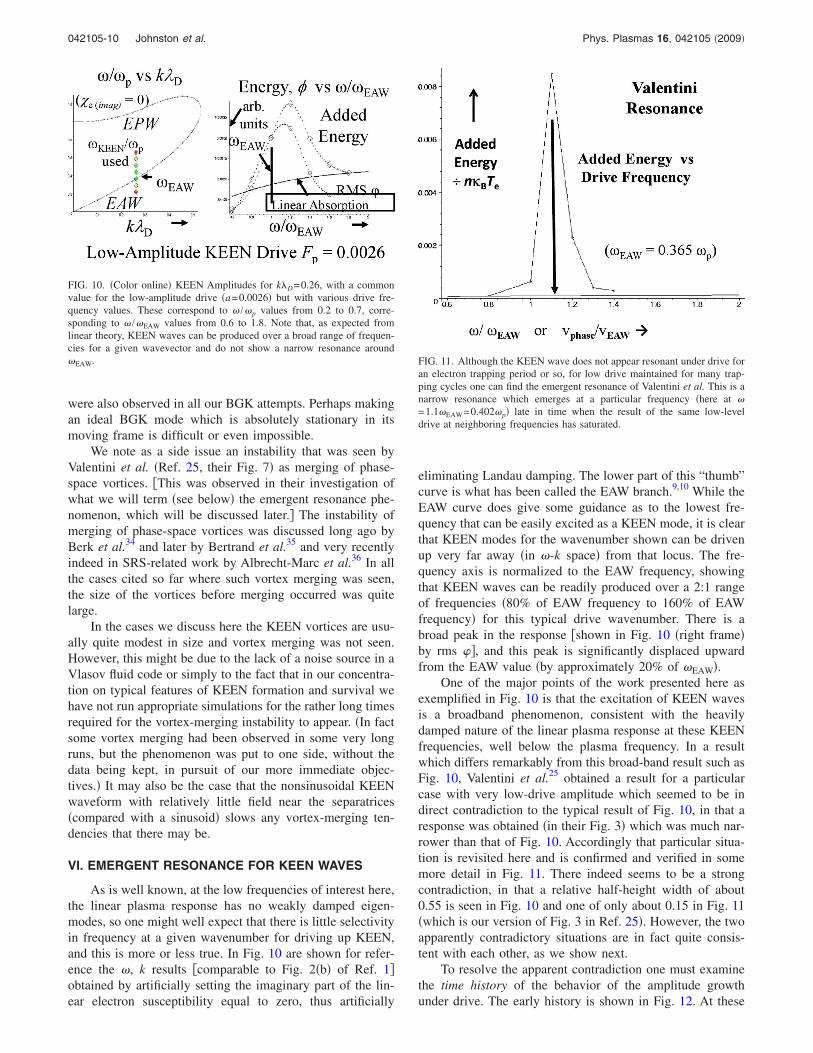
As is well known, at the low frequencies of interest here,the linear plasma response has no weakly damped eigen-modes, so one might well expect that there is little selectivityin frequency at a given wavenumber for driving up KEEN,and this is more or less true. In Fig. 10 are shown for refer-ence the �, k results �comparable to Fig. 2�b� of Ref. 1�obtained by artificially setting the imaginary part of the lin-ear electron susceptibility equal to zero, thus artificially
eliminating Landau damping. The lower part of this “thumb”curve is what has been called the EAW branch.9,10 While theEAW curve does give some guidance as to the lowest fre-quency that can be easily excited as a KEEN mode, it is clearthat KEEN modes for the wavenumber shown can be drivenup very far away �in �-k space� from that locus. The fre-quency axis is normalized to the EAW frequency, showingthat KEEN waves can be readily produced over a 2:1 rangeof frequencies �80% of EAW frequency to 160% of EAWfrequency� for this typical drive wavenumber. There is abroad peak in the response �shown in Fig. 10 �right frame�by rms ��, and this peak is significantly displaced upwardfrom the EAW value �by approximately 20% of �EAW�.
One of the major points of the work presented here asexemplified in Fig. 10 is that the excitation of KEEN wavesis a broadband phenomenon, consistent with the heavilydamped nature of the linear plasma response at these KEENfrequencies, well below the plasma frequency. In a resultwhich differs remarkably from this broad-band result such asFig. 10, Valentini et al.25 obtained a result for a particularcase with very low-drive amplitude which seemed to be indirect contradiction to the typical result of Fig. 10, in that aresponse was obtained �in their Fig. 3� which was much nar-rower than that of Fig. 10. Accordingly that particular situa-tion is revisited here and is confirmed and verified in somemore detail in Fig. 11. There indeed seems to be a strongcontradiction, in that a relative half-height width of about0.55 is seen in Fig. 10 and one of only about 0.15 in Fig. 11�which is our version of Fig. 3 in Ref. 25�. However, the twoapparently contradictory situations are in fact quite consis-tent with each other, as we show next.
To resolve the apparent contradiction one must examinethe time history of the behavior of the amplitude growthunder drive. The early history is shown in Fig. 12. At these
FIG. 10. �Color online� KEEN Amplitudes for k�D=0.26, with a commonvalue for the low-amplitude drive �a=0.0026� but with various drive fre-quency values. These correspond to � /�p values from 0.2 to 0.7, corre-sponding to � /�EAW values from 0.6 to 1.8. Note that, as expected fromlinear theory, KEEN waves can be produced over a broad range of frequen-cies for a given wavevector and do not show a narrow resonance around�EAW. FIG. 11. Although the KEEN wave does not appear resonant under drive for
an electron trapping period or so, for low drive maintained for many trap-ping cycles one can find the emergent resonance of Valentini et al. This is anarrow resonance which emerges at a particular frequency �here at �=1.1�EAW=0.402�p� late in time when the result of the same low-leveldrive at neighboring frequencies has saturated.
042105-10 Johnston et al. Phys. Plasmas 16, 042105 �2009�
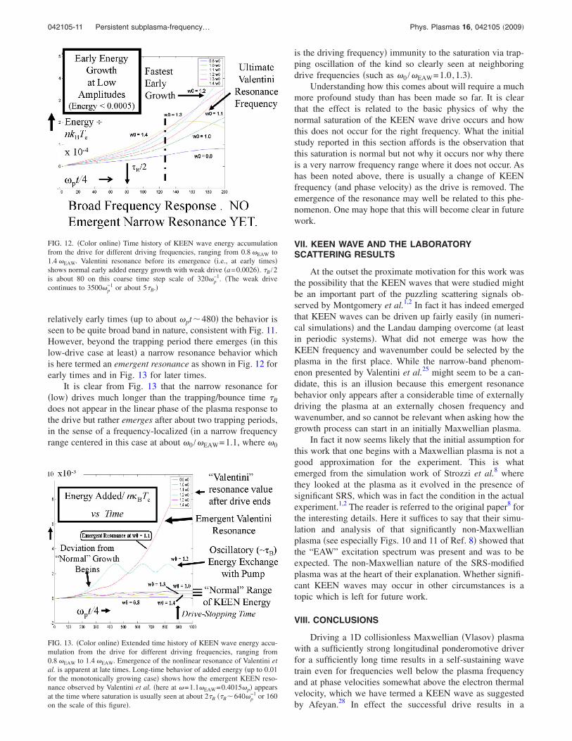
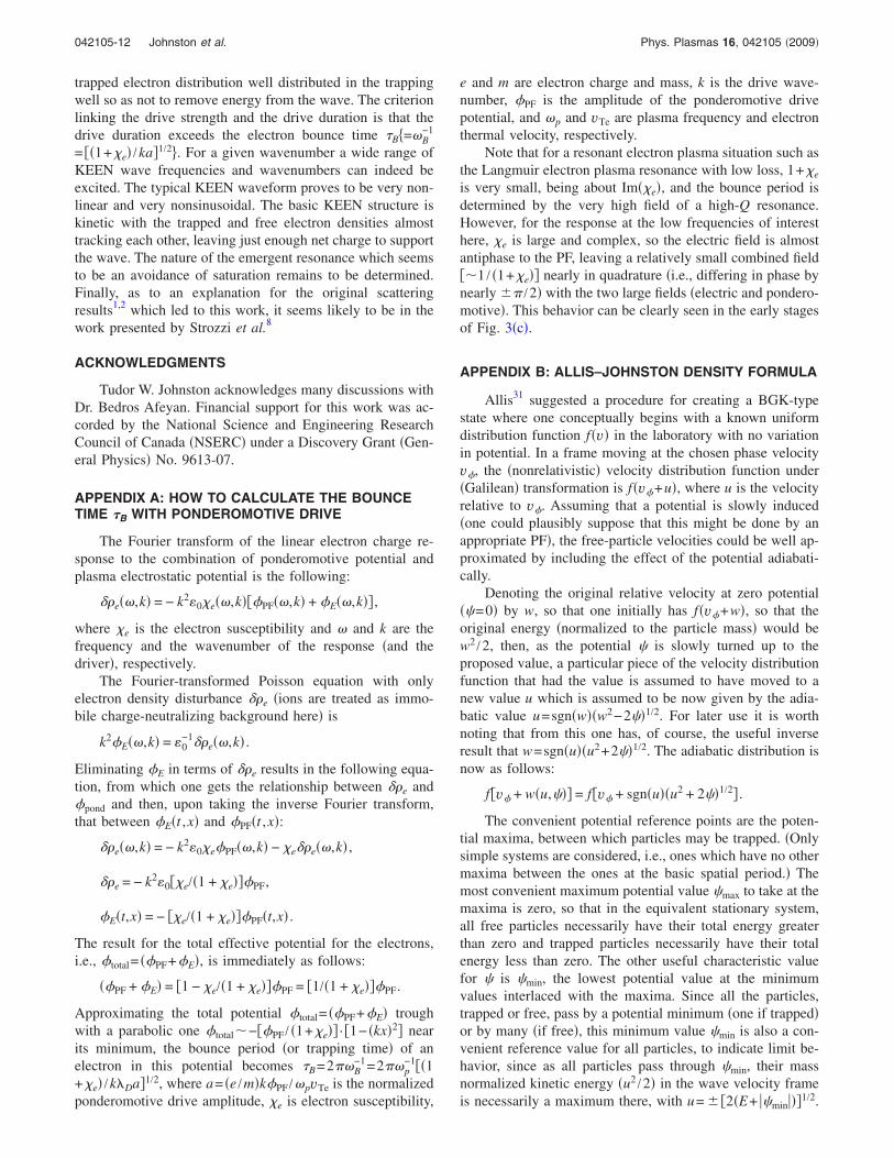
relatively early times �up to about �pt�480� the behavior isseen to be quite broad band in nature, consistent with Fig. 11.However, beyond the trapping period there emerges �in thislow-drive case at least� a narrow resonance behavior whichis here termed an emergent resonance as shown in Fig. 12 forearly times and in Fig. 13 for later times.
It is clear from Fig. 13 that the narrow resonance for�low� drives much longer than the trapping/bounce time �B
does not appear in the linear phase of the plasma response tothe drive but rather emerges after about two trapping periods,in the sense of a frequency-localized �in a narrow frequencyrange centered in this case at about �0 /�EAW=1.1, where �0
is the driving frequency� immunity to the saturation via trap-ping oscillation of the kind so clearly seen at neighboringdrive frequencies �such as �0 /�EAW=1.0,1.3�.
Understanding how this comes about will require a muchmore profound study than has been made so far. It is clearthat the effect is related to the basic physics of why thenormal saturation of the KEEN wave drive occurs and howthis does not occur for the right frequency. What the initialstudy reported in this section affords is the observation thatthis saturation is normal but not why it occurs nor why thereis a very narrow frequency range where it does not occur. Ashas been noted above, there is usually a change of KEENfrequency �and phase velocity� as the drive is removed. Theemergence of the resonance may well be related to this phe-nomenon. One may hope that this will become clear in futurework.
VII. KEEN WAVE AND THE LABORATORYSCATTERING RESULTS
At the outset the proximate motivation for this work wasthe possibility that the KEEN waves that were studied mightbe an important part of the puzzling scattering signals ob-served by Montgomery et al.1,2 In fact it has indeed emergedthat KEEN waves can be driven up fairly easily �in numeri-cal simulations� and the Landau damping overcome �at leastin periodic systems�. What did not emerge was how theKEEN frequency and wavenumber could be selected by theplasma in the first place. While the narrow-band phenom-enon presented by Valentini et al.25 might seem to be a can-didate, this is an illusion because this emergent resonancebehavior only appears after a considerable time of externallydriving the plasma at an externally chosen frequency andwavenumber, and so cannot be relevant when asking how thegrowth process can start in an initially Maxwellian plasma.
In fact it now seems likely that the initial assumption forthis work that one begins with a Maxwellian plasma is not agood approximation for the experiment. This is whatemerged from the simulation work of Strozzi et al.8 wherethey looked at the plasma as it evolved in the presence ofsignificant SRS, which was in fact the condition in the actualexperiment.1,2 The reader is referred to the original paper8 forthe interesting details. Here it suffices to say that their simu-lation and analysis of that significantly non-Maxwellianplasma �see especially Figs. 10 and 11 of Ref. 8� showed thatthe “EAW” excitation spectrum was present and was to beexpected. The non-Maxwellian nature of the SRS-modifiedplasma was at the heart of their explanation. Whether signifi-cant KEEN waves may occur in other circumstances is atopic which is left for future work.
VIII. CONCLUSIONS
Driving a 1D collisionless Maxwellian �Vlasov� plasmawith a sufficiently strong longitudinal ponderomotive driverfor a sufficiently long time results in a self-sustaining wavetrain even for frequencies well below the plasma frequencyand at phase velocities somewhat above the electron thermalvelocity, which we have termed a KEEN wave as suggestedby Afeyan.28 In effect the successful drive results in a
FIG. 12. �Color online� Time history of KEEN wave energy accumulationfrom the drive for different driving frequencies, ranging from 0.8 �EAW to1.4 �EAW. Valentini resonance before its emergence �i.e., at early times�shows normal early added energy growth with weak drive �a=0.0026�. �B /2is about 80 on this coarse time step scale of 320�p
−1. �The weak drivecontinues to 3500�p
−1 or about 5�B.�
FIG. 13. �Color online� Extended time history of KEEN wave energy accu-mulation from the drive for different driving frequencies, ranging from0.8 �EAW to 1.4 �EAW. Emergence of the nonlinear resonance of Valentini etal. is apparent at late times. Long-time behavior of added energy �up to 0.01for the monotonically growing case� shows how the emergent KEEN reso-nance observed by Valentini et al. �here at �=1.1�EAW=0.4015�p� appearsat the time where saturation is usually seen at about 2�B ��B�640�p
−1 or 160on the scale of this figure�.
042105-11 Persistent subplasma-frequency… Phys. Plasmas 16, 042105 �2009�
trapped electron distribution well distributed in the trappingwell so as not to remove energy from the wave. The criterionlinking the drive strength and the drive duration is that thedrive duration exceeds the electron bounce time �B�=�B
−1
= ��1+e� /ka�1/2 . For a given wavenumber a wide range ofKEEN wave frequencies and wavenumbers can indeed beexcited. The typical KEEN waveform proves to be very non-linear and very nonsinusoidal. The basic KEEN structure iskinetic with the trapped and free electron densities almosttracking each other, leaving just enough net charge to supportthe wave. The nature of the emergent resonance which seemsto be an avoidance of saturation remains to be determined.Finally, as to an explanation for the original scatteringresults1,2 which led to this work, it seems likely to be in thework presented by Strozzi et al.8
ACKNOWLEDGMENTS
Tudor W. Johnston acknowledges many discussions withDr. Bedros Afeyan. Financial support for this work was ac-corded by the National Science and Engineering ResearchCouncil of Canada �NSERC� under a Discovery Grant �Gen-eral Physics� No. 9613-07.
APPENDIX A: HOW TO CALCULATE THE BOUNCETIME �B WITH PONDEROMOTIVE DRIVE
The Fourier transform of the linear electron charge re-sponse to the combination of ponderomotive potential andplasma electrostatic potential is the following:
��e��,k� = − k2�0e��,k���PF��,k� + �E��,k�� ,
where e is the electron susceptibility and � and k are thefrequency and the wavenumber of the response �and thedriver�, respectively.
The Fourier-transformed Poisson equation with onlyelectron density disturbance ��e �ions are treated as immo-bile charge-neutralizing background here� is
k2�E��,k� = �0−1��e��,k� .
Eliminating �E in terms of ��e results in the following equa-tion, from which one gets the relationship between ��e and�pond and then, upon taking the inverse Fourier transform,that between �E�t ,x� and �PF�t ,x�:
��e��,k� = − k2�0e�PF��,k� − e��e��,k� ,
��e = − k2�0�e/�1 + e���PF,
�E�t,x� = − �e/�1 + e���PF�t,x� .
The result for the total effective potential for the electrons,i.e., �total= ��PF+�E�, is immediately as follows:
��PF + �E� = �1 − e/�1 + e���PF = �1/�1 + e���PF.
Approximating the total potential �total= ��PF+�E� troughwith a parabolic one �total�−��PF / �1+e�� · �1− �kx�2� nearits minimum, the bounce period �or trapping time� of anelectron in this potential becomes �B=2��B
−1=2��p−1��1
+e� /k�Da�1/2, where a= �e /m�k�PF /�pvTe is the normalizedponderomotive drive amplitude, e is electron susceptibility,
e and m are electron charge and mass, k is the drive wave-number, �PF is the amplitude of the ponderomotive drivepotential, and �p and vTe are plasma frequency and electronthermal velocity, respectively.
Note that for a resonant electron plasma situation such asthe Langmuir electron plasma resonance with low loss, 1+e
is very small, being about Im�e�, and the bounce period isdetermined by the very high field of a high-Q resonance.However, for the response at the low frequencies of interesthere, e is large and complex, so the electric field is almostantiphase to the PF, leaving a relatively small combined field��1 / �1+e�� nearly in quadrature �i.e., differing in phase bynearly �� /2� with the two large fields �electric and pondero-motive�. This behavior can be clearly seen in the early stagesof Fig. 3�c�.
APPENDIX B: ALLIS–JOHNSTON DENSITY FORMULA
Allis31 suggested a procedure for creating a BGK-typestate where one conceptually begins with a known uniformdistribution function f�v� in the laboratory with no variationin potential. In a frame moving at the chosen phase velocityv�, the �nonrelativistic� velocity distribution function under�Galilean� transformation is f�v�+u�, where u is the velocityrelative to v�. Assuming that a potential is slowly induced�one could plausibly suppose that this might be done by anappropriate PF�, the free-particle velocities could be well ap-proximated by including the effect of the potential adiabati-cally.
Denoting the original relative velocity at zero potential��=0� by w, so that one initially has f�v�+w�, so that theoriginal energy �normalized to the particle mass� would bew2 /2, then, as the potential � is slowly turned up to theproposed value, a particular piece of the velocity distributionfunction that had the value is assumed to have moved to anew value u which is assumed to be now given by the adia-batic value u=sgn�w��w2−2��1/2. For later use it is worthnoting that from this one has, of course, the useful inverseresult that w=sgn�u��u2+2��1/2. The adiabatic distribution isnow as follows:
f�v� + w�u,��� = f�v� + sgn�u��u2 + 2��1/2� .
The convenient potential reference points are the poten-tial maxima, between which particles may be trapped. �Onlysimple systems are considered, i.e., ones which have no othermaxima between the ones at the basic spatial period.� Themost convenient maximum potential value �max to take at themaxima is zero, so that in the equivalent stationary system,all free particles necessarily have their total energy greaterthan zero and trapped particles necessarily have their totalenergy less than zero. The other useful characteristic valuefor � is �min, the lowest potential value at the minimumvalues interlaced with the maxima. Since all the particles,trapped or free, pass by a potential minimum �one if trapped�or by many �if free�, this minimum value �min is also a con-venient reference value for all particles, to indicate limit be-havior, since as all particles pass through �min, their massnormalized kinetic energy �u2 /2� in the wave velocity frameis necessarily a maximum there, with u= � �2�E+ ��min���1/2.
042105-12 Johnston et al. Phys. Plasmas 16, 042105 �2009�
In general, particles with total energy E have relative veloc-ity u= � �2�E−���1/2 and if these particles pass by the po-tential maxima �as all free particles do� their relative velocitymagnitude is least there, where �=0, so that at the potentialmaxima u= � �2E�1/2. For free particles �E�0� one has u2
�−2��0, and there is thus a gap in the free-particle veloc-ity distribution function of ��−2��1/2 around v�, withinwhich one may find trapped particles.
Allis considered an initially Maxwellian distribution inthe laboratory frame, here written as exp�−v2 /2�, since thenormalizing velocity is here taken as �kT /m�1/2. In the wavephase velocity �v=v�� frame, with relative velocity w, onehas exp�−�v�+w�2 /2�. The Allis procedure for the free par-ticles with nonzero � is to replace w by u, the adiabatic valueobtained if the potentially were raised very slowly, to give adistribution function proportional to exp�−�v�+w�u ,���2 /2 .The Allis analysis thus began with the following expressionfor f free�u�, in which the distribution function density for aMaxwellian, exp�−�v�+w�2 /2�, is to be assigned to a newvelocity v=v�+u, as indicated below,
f free�v�,u,�� � exp�− �v� + w�u,���2/2 ,
f free�v�,u,�� � exp�− �v� + sgn�u���u2 + 2���1/2 2/2� .
This adiabatic free-particle adiabatic result is also theone given by Eliasson and Shukla30 among others. As re-marked above, for nonzero � the result is a gap in the free-particle velocity distribution function of ��−2��1/2 aroundv�, and it is there that one may find trapped particles.
No particular value is indicated here for the normalizingconstant factor which is needed so the total number of elec-trons is conserved. �For the uniform Maxwellian with nopotential gradient one has the usual Maxwellian valueC�=0= �2��−1/2, and if there were only free particles theLiouville theorem would indicate the correction for the spa-tially varying velocity would be simply w /u.� Particle trap-ping is assumed and this is to be accounted for in the end, byintegrating over a spatial period of �, to obtain a normalizingconstant that can be denoted by C�. This numerical correc-tion is not discussed here, so all that is required here is theform of the distribution function, and the symbol used issimply the � symbol.
Turning now to the trapped particles, when the steady-state BGK approximation applies, as many particles are go-ing in one direction as are going in the opposite direction, thetrapped-particle distribution function must then be even in u,and thus it must be even in w�u ,��, which is of course nottrue for the shifted Maxwellian. However Allis noted that,for an original Maxwellian distribution, the expression justgiven for the free particles could also be rewritten in a formfor which the parts which are explicitly separated into twoparts which are respectively even and odd in w�u ,��, asfollows:
f free�w�u,��� � exp�− �v� + w�u,���2/2
� exp��− v�2 /2 − w�u,���2/2
��cosh�v�w�u,��� − sinh�v�w�u,��� .
Allis proposed simply dropping this odd second term �onthe grounds that mixing would tend to reduce it to zero� andthus obtained the following functional form for the trappedparticles which could plausibly be made from a Maxwellian,namely, the following expression:
f trapped�v�,w�u,��� � exp�− v�2 /2 − w�u,��2/2�
��cosh�v�w�u,��� .
Because of the choice of potential used here there are nodifficulties of the kind encountered by Allis due to disconti-nuities across square roots of w2 and the like. There is, how-ever, another apparent difficulty for the trapped particles andthat is the fact that, if w2 /2 is negative real, as required fortrapped particles, then w itself must be pure imaginary, sothe argument of cosh�v�w�u ,��� is also pure imaginary. Re-markably enough this presents no formal problem, since �asis well known� for real z, cosh�iz� is simply cos�z� which isalso real and even in z. More particularly, we have a newform for cosh�v�w�u ,���:
cosh�v�w�u,��� = cos�iv�w�u,���
= cos�sgn�u�v��− 2� − u2�1/2� .
Hence for the trapped particles with negative energy, the cor-rected Allis formula becomes the real function as given next:
f trapped�v�,�− 2��1/2 � u � − �− 2��1/2,��
� exp�− v�2 /2 + �− 2� − u2�/2�
�cos�sgn�u�v��− 2� − u2�1/2� .
This trapped-particle distribution function, being the Al-lis concept as modified by Johnston, is what is here referredto as the AJ distribution. It is the result of extending theoriginal Maxwellian distribution into the complex plane �i.e.,to imaginary velocities�. However, given that the present ap-plication is not a Laplace transform or Fourier transform cal-culation, where analytic continuation is often the rule, thejustification for the application of this form is not at all clear.
Before discussing how one might employ this formula-tion, it is worth recalling some fundamentals of trapping.Although the free-particle distribution evolution can be adia-batic, essentially tracking the quasistationary orbits in phasespace, the trapped-particle distribution cannot be really adia-batic, since trapping is inherently and essentially a nonadia-batic process. If one defines instantaneous pseudosepara-trices �i.e., defined as if the waves, which are actually slowlyvarying in the wave frame, were not evolving at all so suchpseudoseparatrices could be defined�, it is clear that, as thewave is slowly growing, particles become trapped by cross-ing these pseudoseparatrices in the vicinity of their �x ,v� Xpoints, at zero energy, in an essentially nonadiabatic processwhich can thus drastically separate once close phase-spaceneighbors in their future dynamics. Also the particles whichare captured into the trapping population are necessarily lostfrom the free-particle population, presumably originally fromthe free-particle distribution near the separatrices. This mi-croscopic population-transfer aspect is completely ignoredhere, as is usual in most models of this kind. �Whatever thetrapped particle distribution function has been hypothesized
042105-13 Persistent subplasma-frequency… Phys. Plasmas 16, 042105 �2009�
has, in general, been simply added to the undepleted free-particle distribution function and then overall particle conser-vation enforced simply by overall numerical integration overspace and renormalization.�
The modified Allis distribution would work if one had aplausible suggestion for the original distribution function inenergy to use for the trapped particles, i.e., the equivalent forthe Maxwellian that was used for the free particles. To dothis one might well have to involve the entire history of thedrive. Since the particles come through the separatrix, whereE�0, one might use the E=0, but that would give a flatdensity over the entire trapped region, which is nothing likethe valley centered on �min that is actually observed. Anotherpossibility is to imagine the trapping process to be somewhatlike a leak through a barrier, in which case the Maxwellianexponential might be a plausible guess. In the event, it wasdecided to simply try the formula to see if it worked. Aninteresting feature of this particular distribution comparedwith others is that, apart from the overall number conserva-tion, there are no adjustable parameters.
Although the original Allis notation has been followed�more or less� to this point, it is now more convenient torewrite the results for the free and trapped particles using theoriginal total energy E�=w2 /2� in the wave frame.
FAJ��free,E � 0,�� � exp�− �v� � �2�E − ���1/2�2/2� .
One actually plots this as a function of v by choosing E�0 then calculating from the chosen value of E and the localvalue for � the value for FAJ� �free, E�0, �� and for v�
=v�� �2�E−���1/2 and then plotting them against each other.For the trapped particles we have the following result:
FAJ�trapped,� E 0,��
� exp�− v�2 /2 + �E − ���cos�v��2�E − ���1/2 .
The function of v for the trapped particles is now plotted asby choosing E 0 then proceeding as for the free particlesbut using FAJ �trapped, � E 0, ��. It is worth noting thatfor the trapped-particle AJ form, at v� ��=�min� the trappedparticle density value is a minimum only for v��1 �i.e.,only for phase velocity greater than the thermal velocity�kBT /m�1/2 which is also the inflection point for the Max-wellian�. However, in the cases of interest for KEEN wavesthis was always true for the cases considered.
At the velocity separatrices �the values dividing free par-ticles from trapped particles� one has E=0. Where the poten-tial has a value � in the wave, the two values thus obtainedfor v� for E=0 �i.e., v�=v�� �−��1/2� give the velocity val-ues corresponding to the separatrices. Note that at the sepa-ratrices there are generally discontinuities in the distributionfunction between the trapped and free-particle values, exceptat �=0, where both formulas give exp�−v�
2 /2�. Recall
FAJ��free,E = 0,�� � exp�− �v� � �2�− ���1/2 2/2�
� exp��− v�2 /2 − � � v��− ��1/2� ,
FAJ�trapped,E = 0,�� � exp�− v�2 /2 − ��
�cos�v��2�− ���1/2 .
A final point to note is that when v�, �2�−���1/2 exceeds� /2, i.e., when the potential well is too deep, the cosinefunction passes through zero, and, since negative values for adistribution function are meaningless, some special measures�such as truncation� would be required.
The procedure actually used to obtain the final self-consistent BGK-like result was to assume the initial valuesfor � and to iterate this and the corresponding distributionfunction �including spatial integration and renormalization sothat the total charge is conserved� to an equilibrium result.�This procedure may sometimes fail in that it does not al-ways converge to a nontrivial equilibrium in the sense that �values may iterate toward zero in some cases.� When a sat-isfactory equilibrium result is obtained with usefully large �,this self-consistent BGK distribution function result is thenused as an initial condition for the Vlasov code to verify itsstability. �While the existence of a BGK equilibrium arrivedat in this nondynamic iteration does not automatically guar-antee its survivability in a dynamic Vlasov–Poisson simula-tion, in practice, when the iteration procedure gives nonzeroBGK results, they survive well in the subsequent simula-tion.� As shown by the data presented in Fig. 17 the AJ resultcan work quite well, at least sometimes. �Because this is aside issue for the work of this paper, the matter was notpursued further. However, it might be interesting in othercontexts to see how well this AJ formulation performs over arange of drive strengths and phase velocities.�
1D. S. Montgomery, R. J. Focia, H. A. Rose, D. A. Russell, J. A. Cobble,J. C. Fernández, and R. P. Johnson, Phys. Rev. Lett. 87, 155001 �2001�.
2D. S. Montgomery, J. A. Cobble, J. C. Fernández, R. J. Focia, R. P.Johnson, N. Renard-LeGalloudec, H. A. Rose, D. A. Russell, H. A. Rose,and D. A. Russell, Phys. Plasmas 9, 2311 �2002�.
3H. A. Rose and D. A. Russell, Phys. Plasmas 8, 4784 �2001�.4K. Watanabe and T. Taniuti, J. Phys. Soc. Jpn. 43, 1819 �1977�.5S. P. Gary and R. L. Tokar, Phys. Fluids 28, 2439 �1985�.6H. Schamel, Phys. Scr. 20, 336 �1979�.7V. P. Krapchev and A. K. Ram, Phys. Rev. A 22, 1229 �1980�.8D. J. Strozzi, E. A. Williams, A. B. Langdon, and A. Bers, Phys. Plasmas
14, 013104 �2007�.9R. Pottelette, R. E. Ergun, R. A. Treumann, M. Berthomier, C. W. Carlson,J. P. McFadden, and I. Roth, Geophys. Res. Lett. 26, 2629, DOI:10.1029/1999GL900462 �1999�.
10P. K. Shukla, M. A. Hellberg, and L. Stenflo, J. Atmos. Sol.-Terr. Phys.65, 355 �2003�.
11I. Bernstein, J. M. Greene, and M. D. Kruskal, Phys. Rev. 108, 546�1957�.
12H. Schamel, Phys. Plasmas 7, 4831 �2000�, and references therein.13J. P. Holloway and J. J. Dorning, Phys. Lett. A 138, 279 �1989�.14J. P. Holloway and J. J. Dorning, Phys. Rev. A 44, 3856 �1991�.15M. Buchanan and J. J. Dorning, Phys. Rev. Lett. 70, 3732 �1993�; Phys.
Rev. E 50, 1465 �1994� c15 c15a c15b c15c 52, 3015 �1995�.16C. Lancellotti and J. J. Dorning, Phys. Rev. Lett. 81, 5137 �1998�.17C.-H. Lin, J. K. Chao, and C. Z. Cheng, Phys. Plasmas 2, 4195 �1995�.18G. Manfredi, Phys. Rev. Lett. 79, 2815 �1997�.19M. V. Medvedev, P. H. Diamond, M. N. Rosenbluth, and V. I.
Shevchenko, Phys. Rev. Lett. 81, 5824 �1998�.20M. Brunetti, F. Califano, and F. Pegoraro, Phys. Rev. E 62, 4109 �2000�.21G. Vetoulis and M. Oppenheim, Phys. Rev. Lett. 86, 1235 �2001�.22D. L. Newman, M. V. Goldman, M. Spector, and F. Perez, Phys. Rev. Lett.
86, 1239 �2001�.23B. Eliasson and P. K. Shukla, Phys. Rep. 422, 225 �2006�.24K. Saeki, P. Michelsen, H. L. Pecseli, and J. J. Rasmussen, Phys. Rev.
Lett. 42, 501 �1979�.25F. Valentini, T. M. O’Neil, and D. H. E. Dubin, Phys. Plasmas 13, 052303
�2006�.26T.W. Johnston, B. Afeyan, P. Bertrand, and A. Ghizzo, Paper QP1 136,
042105-14 Johnston et al. Phys. Plasmas 16, 042105 �2009�
Bull. Am. Phys. Soc. 46�8�, 282 �2001�; 47�9�, 277 �2002�; T.W. Johnstonand B. Afeyan, Paper CP1 38, ibid. 48�7�, 067 �2003�; B. Afeyan, V.Savchenko, K. Won, and T.W. Johnston, Paper CP1 39, ibid. 48�7�, 068�2003�; T.W. Johnston, Y. Tyshetskiy, and B. Afeyan, Paper BP1 52, ibid.49�8�, 40 �2004�; Y. Tyshetskiy, T.W. Johnston, and B. Afeyan, Paper BP153, ibid. 49�8�, 40 �2004�; J. Kline, B. Afeyan, W. Bertsche, N. Kurnit, D.Montgomery, V. Savchenko, and K. Won, Paper BP1 56, ibid. 49�8�, 41�2004�; Y. Tyshetskiy, T.W. Johnston, and B. Afeyan, Paper LP1 74, ibid.50�8�, 242 �2005�; K. Won, B. Afeyan, V. Savchenko, P. Morrison, and T.W. Johnston, Paper LP1 75, ibid. 50�8�, 242 �2005�; T.W. Johnston, Y.Tyshetskiy, and B. Afeyan, Paper UP1 118, ibid. 51�7�, 288 �2006�; V.Savchenko, K. Won, and B. Afeyan, Paper UP1 119, ibid. 51�7�, 288�2006�; B. Afeyan and M. Charbonneau-Lefort, Paper GP8 37, ibid.52�16�, 116 �2007�.
27B. Afeyan, K. Won, V. Savchenko, T. W. Johnston, A. Ghizzo, and P.Bertrand, “Kinetic electrostatic electron nonlinear �KEEN� Waves andtheir interactions driven by the PF of crossing laser beams,” in ThirdInternational Conference on Inertial Fusion Sciences and Applications,Monterey, CA, 7–12 September 2003, edited by B. Hammel, D. Meyer-hofer, J. Meyer-ter-Vehn, and H. Azechi �American Nuclear Society,LaGrange Park, IL, 2004�, Paper No. M034, p. 213.
28B. Afeyan, Bull. Am. Phys. Soc. 49, 288 �2004�.29C. Z. Cheng and G. Knorr, J. Comput. Phys. 22, 330 �1976�.
30A. Ghizzo, P. Bertrand, M. Shoucri, T. W. Johnston, E. Fijalkow, and M.R. Feix, J. Comput. Phys. 90, 431 �1990�.
31R. N. Bracewell, The Fourier Transform and Its Applications �McGraw-Hill, New York, 1978�; also Science 248, 697 �1990�; A. Ghizzo, T. Rev-eille, P. Bertrand, T. W. Johnston, J. Lebas, and M. Shoucri, J. Comput.Phys. 118, 356 �1995�. The application here using the Hilbert transform isvery simple, but the treatment of much more complicated situations can befound via the Hilbert–Huang analysis, which uses empirical mode decom-position, as set out in Hilbert–Huang Transform and Its Applications,Interdisciplinary Mathematical Sciences Vol. 5, edited by N. E. Huang andS. S. P. Shen �World Scientific, Singapore, 2005�.
32B. Eliasson and P. K. Shukla, Phys. Rev. E 71, 046402 �2005�.33W. P. Allis, in In Honor of Philip M. Morse, edited by H. Feshbach and K.
Ingard �MIT, Cambridge, 1969�, pp. 21–42.34H. L. Berk, C. E. Nielsen, and K. V. Roberts, Phys. Fluids 13, 980 �1970�.35P. Bertrand, A. Ghizzo, M. R. Feix, E. Fijalkow, P. Mineau, and N. D. Suh,
and M. Shoucri, Proceedings of the International Workshop on NonlinearPhenomena in Vlasov Plasmas, Cargèse, France, 11–16 July 1988, editedby F. Doveil �Editions de Physique d’Orsay, Orsay, 1989�, p. 109; see alsoA. Ghizzo, B. Izrar, P. Bertrand, E. Fijalkov, M. R. Feix, and M. Shoucri,Phys. Fluids 31, 72 �1988�.
36M. Albrecht-Marc, A. Ghizzo, T. W. Johnston, T. Réveillé, D. Del Sarto,and P. Bertrand, Phys. Plasmas 14, 072704 �2007�.
042105-15 Persistent subplasma-frequency… Phys. Plasmas 16, 042105 �2009�


![arXiv:1705.06806v1 [physics.plasm-ph] 18 May 2017 · the interaction between the ion beam pulse and back-ground plasma. Kinetic simulation. Electrostatic kinetic simulations are performed](https://img.pdfslide.net/doc/110x75/5f7845a8af9bcb2e0a348105/arxiv170506806v1-18-may-2017-the-interaction-between-the-ion-beam-pulse-and.jpg)