Embed Size (px)
Citation preview

27
Person Following Robot with Vision-based and Sensor Fusion Tracking Algorithm
Takafumi Sonoura, Takashi Yoshimi, Manabu Nishiyama, Hideichi Nakamoto, Seiji Tokura and Nobuto Matsuhira
Corporate R&D Center, Toshiba Corporation Japan
1. Introduction
Current demographics show that Japan is experiencing a combination of an aging population and a declining birth rate. Therefore, interest is growing in the potential of human symbiotic robots such as daily life support robots that can care for the aged and young children. Human symbiotic robots require sophisticated capabilities to achieve symbiosis and interaction with humans. It is essential for these robots to understand human intentions, and interact with humans and the environment. We call these technologies, which create real value for people and society, "human-centric technologies", and have developed some home robots and human symbiotic robots (Yoshimi et al., 2004; Matsuhira et al., 2005a; Matsuhira et al., 2005b). The development of these robots is a typical target for human-centric technologies, but these technologies are not only applicable for robots but also for all machines that humans use. In the development of human symbiotic robots, we set one of the target criteria as the ability to recognize individuals using vision, and to understand situations in order to provide various real-life services to humans. To realize this target criterion, we think that the principal capabilities required are accurate vision and recognition of specified individuals who are in the vicinity. Moreover, another important capability common to the human symbiotic robot is that of moving safely near humans. In light of the above considerations, we have developed ApriAttendaTM shown in Fig.1, a person following robot that finds a specified person using visual tracking functions and follows him/her while avoiding obstacles (Yoshimi et al., 2006). Person following robots developed until now use various types of cameras for detecting a target person, and some of them use other sensors (Schlegl et al., 1998; Sidenbladh et al., 1999; Kwon et al., 2005; Cielniak et al., 2005; Kobilarov et al., 2006). Our newly developed robot adopts a stereo vision system, and additionally a Laser Range Finder (LRF) is mounted on the robot body to enhance the performance of person following motion. A person following robot has to distinguish the target object from other objects and recognize it by some methods. And the robot has to get the information of the target position, and continue following it quickly so as not to be left behind. At this time, camera information is often used to recognize the target. In addition, in the case of the stereo systems using two or more cameras, the distance information for the person following motion can be obtained. O
pen
Acc
ess
Dat
abas
e w
ww
.i-te
chon
line.
com
Source: Computer Vision, Book edited by: Xiong Zhihui, ISBN 978-953-7619-21-3, pp. 538, November 2008, I-Tech, Vienna, Austria
www.intechopen.com

Computer Vision
520
The stereo vision system generates information on distance to the object being tracked. It is helpful for the person following motion but unsatisfactory, because this information has insufficient accuracy for quick person following motion. Using the image data with a rough pixel limited by the trade-off with the calculation speed, many quantization errors will occur. So, we designed a tracking system that uses highly accurate measurement information by operating in combination with LRF. Our system has a feature to change the fusion rate of vision and LRF data according to the congestion level of the movement space, and so we achieved quick and stable person following motion. This article introduces the mobile robot system to which the vision system is applied. And the behaviour of the vision system mounted on the mobile robot is shown. Moreover, the problems of the tracking system applied to the robot system are pointed out, and a new sensor fusion method to overcome the problems is proposed. Additionally, the effect of the proposed method is shown by referring to experiment results.
Fig. 1. Person Following Robot ApriAttendaTM (without LRF)
Size φ450[m m ]×H900[m m ]
W eight approx. 30[kg]
Sensors C C D C am era×2 with Pan/Tilt M otion
Ultrasonic Sensors (8direction)
Laser Range Finder×1
M ovem ent D rive M otors and W heels×2 (independently driven)
M ax Velocity 1.2 [m /s] (4.3[km /h])
M ax Acceleration 2.0 [m /s 2̂]
Interfaces TFT Liquid C rystal D isplay, M icrophones, Speakers
Pow er Lithium -Ion Battery
O peration Tim e approx. 1[hour]
Table 1. Specifications of ApriAttendaTM
www.intechopen.com

Person Following Robot with Vision-based and Sensor Fusion Tracking Algorithm
521
2. Person following robot ~ robotics application of vision systems ~
2.1 Robot specifications
The person following robot, ApriAttendaTM, whose shape consists of two spheres, one mounted on top of the other, is shown in Fig.1. It is designed to look friendly and gentle, so many people feel that it is safe and harmonizes with the surrounding environment. The specifications of ApriAttendaTM are shown in Table 1. The robot is approximately 450mm in diameter, 900mm in height, and 30kg in weight, and it moves by two independently driven wheels. The robot gets the image of the target person by means of two CCD cameras on its head with pan/tilt motions. The robot can get higher-resolution images in real time using stereo vision than in the case of using an omnidirectional camera; the accurate recognition of the target person is executed. Furthermore, the robot is equipped with an LRF on its body (Fig.11). It can get high-precision line-scan (direction-distance pare) information. We have designed the size of this robot to enable it to coexist with people who walk around in the home and public facilities, and to look over the objects on standard height desks or tables. The robot can be commanded through verbal communication, the touch panel display mounted on its back, or wireless LAN from an external PC. The robot is powered by lithium-ion batteries and its operation time is about one hour with full batteries. The robot has an inertia absorbing mechanism to maintain stability in case the robot moves or stops suddenly.
2.2 Functions
ApriAttendaTM finds a specified person and follows him/her. Its basic functions involved in following a person are as follows: 1. Tracking the specified people: A developed proprietary image processing algorithm
extracts and recognizes specific individuals, registering the color and texture of their clothing, and distinguishing them from cluttered backgrounds. Additionally, we have strengthened the tracking performance by integration of LRF information. The details are explained below.
2. Following at his/her pace: The robot calculates the distance between the target person and itself using stereo vision and follows him/her with the appropriate speed to keep the distance constant (Fig.2(a)).
3. Avoiding obstacles: The robot uses ultrasonic sensors integrated in the robot’s base to detect obstacles and automatically generates a route to avoid them (Fig.2(b)).
4. Resuming contacting when the robot misses him/her: If the robot loses sight of its target, it searches for the person or calls out to re-establish contact.
The person following motion control, including obstacle avoidance and contact resumption, is explained in detail below. The person following robot equipped with the above mentioned functions is expected to support our daily life from the viewpoints of safety, security and practicality. It will take care of an infant and/or elderly person, and carry baggage as it follows the user in a shopping center as shown in Fig.3.
2.3 System configuration
The system configuration of ApriAttendaTM from the viewpoints of function modules is shown in Fig.4. For the person following function, we have constructed two function modules, the Target Detection Module and the Motion Control Module, in the
www.intechopen.com

Computer Vision
522
ApriAttendaTM’s control system. Two camera images of the target person including cluttered backgrounds are captured concurrently by the original versatile multimedia front-end processing board named MFeP (Sato et al., 2005), and sent to the Target Detection Module. At the Target Detection Module, the target person is detected by the newly developed image processing algorithm, and the result (distance and direction data of the target person from the robot) is sent to the Motion Control Module through the network. At the Motion Control Module, the two wheels and the head of the robot are controlled cooperatively to follow the target person smoothly. LRF is mounted and used to track in this module. The Target Detection Module runs on Windows PC and the Motion Control Module runs on Linux PC, because the Windows PC has many image processing applications, and the robot motion control requires real-time processing. The frame rate of the image processing system is about 15 fps, and the control cycle of the motion control system is 1kHz.
Quickly follow
Slowly follow
People avoid
obstacles
So does
ApriAttenda
a) Moves as the person does (b) Avoid obstacles
Fig. 2. Concept of ApriAttendaTM’s Motion
Fig. 3. Assumed Roles of Person Following Robot
Regarding ApriAttendaTM’s systemization, the open robot controller architecture (Ozaki, 2003) has been adopted to easily integrate the Target Detection Module and the Motion Control Module, because this distributed object technology based architecture can connect a number of software modules easily even if these modules are located on different CPUs. This architecture has already been successfully applied to ApriAlphaTM (Yoshimi et al., 2004).
Babysitting
Watch over the elderly
Carry bags
www.intechopen.com

Person Following Robot with Vision-based and Sensor Fusion Tracking Algorithm
523
Fig. 4. System Configuration of ApriAttendaTM
2.4 Motion controller architecture
A. Person Following Control
The person following robot ApriAttendaTM finds a target person and measures distance and
direction to him/her using stereo vision processing and LRF sensing data. The robot
controls its speed to keep the distance to the person constant and follows him/her. When
the target person moves forward, ApriAttendaTM moves forward, and when the person
stops, the robot moves to a point beside the person and also stops. If the person approaches
too closely to the robot, ApriAttendaTM backs off. Figure 5 shows the configuration of
ApriAttendaTM’s motion control system. It consists of two parts, the Body Motion Control
Module and the Head Motion Control Module which construct the general position control
system. Since the movement of the target person cannot be predicted beforehand, the
highest priority of the person following control is to control the camera head module to
keep the target person at the center of the visual field, robustly. Next, the robot body is
controlled to change its direction to the same direction as the head module, and at the same
time, to move its position to keep the distance to the target person constant under the
nonholonomic constrained condition of its two independently driven wheels system.
B. Obstacle Avoidance Control
In the person following motion, ApriAttendaTM detects the target person by the image processing and LRF sensing system, and checks for obstacles in its way using ultrasonic sensors in parallel. When an obstacle on the robot’s trajectory is found by the ultrasonic sensor, the robot starts to avoid the obstacle, and tries to continue following the person by the vision sensor, so the robot keeps its visual axis to the target person using the degrees of freedom of its head unit and changes the direction of the body and goes around to avoid the obstacle. The avoidance control system is constructed by means of obstacle map written by occupancy grid map and the velocity potential method (Yoshimi et al., 2006). The Avoidance Trajectory Generation Unit in Fig.5 converts the reference information of the robot motion to avoid the obstacle when it exists near the robot.
www.intechopen.com

Computer Vision
524
Motion
Command
Target
Information
Body Data
Head Data
Person Data: Distance & Direction
Following Traj.
Head Traj.Following Traj.
Generation
Avoidance Traj.
Generation
Head Traj.
Compensation
Body Motion Control
Head Motion Control
or
or
Use in "Commad"Motion Mode
Use in "Following"Motion Mode
Body Control Module
Head Control Module Fig. 5. Motion Control System of ApriAttendaTM
3. Vision-based tracking algorithm
A. Feature Parameters for Target Person Detection The most difficult and important problem for the vision-based target detection of the person
following robot is to select the most suitable feature parameter, which expresses the target
person in the captured input image (Schlegel et al., 1998). For the detection of the target
person’s region, we usually check many kinds of features on the specified part of the input
image, such as the position (absolute position and distance from the robot), color, and
movement speed. If the most suitable feature parameter has been selected, the target
detection process is defined to find the part corresponding to the selected parameter from
the input image. However, it is difficult to select the most suitable feature parameter to
detect the target person’s region, because the specified part of the input image moves not
only due to the target person’s but also the robot’s movement; furthermore the detected
color of the specified part may change because of shifts in lighting.
Hirai et al. selected a shape of human back and shoulder for visual tracking of the target person (Hirai et al., 2003). We assumed that the target person usually moves and exists before the background, so we defined that the group of feature points on the person’s region in the input image moves at a certain speed, and/or exists nearer than the background and its position changes continuously. Once a target person is detected as a region of moving and existing before background, we can follow this region using our definition mentioned above. B. Dynamic Switching of Feature Parameters for Target Person Detection To select the most suitable feature parameter for detecting the target person stably while the
person following robot is moving, we have introduced a method of dynamically switching
the feature parameters. This method selects and switches the most suitable feature
parameter for detecting the target person dynamically according to the input image’s
condition, and achieves robust target person detection.
www.intechopen.com

Person Following Robot with Vision-based and Sensor Fusion Tracking Algorithm
525
We have developed a new algorithm to recognize and extract the region of the person from an input image containing a complicated scene for the person following robot ApriAttendaTM. We used two kinds of feature parameters, distance from the robot and movement speed, for detecting the person’s region, and other feature parameters, color and texture, for specifying the target person. The detection of the target person is executed according to the following sequence (Fig.6):
Fig. 6. Image Processing Algorithm of ApriAttendaTM
(a)Finding the person , (b) Processing image
1. Feature points extraction: Some feature points are extracted automatically from the input image. The system sets the feature points on the extracted edges or corner points.
2. Velocity calculation of each feature point: The velocity of each feature point is calculated from the history of its motion.
3. Distance measurement to each feature point: The distance from the robot to each feature point is measured by the stereo vision system.
4. Evaluation of the degree of separation for the most suitable feature parameter selection: The most suitable feature parameter for the person region detection is selected by the distribution of the feature points’ distance and velocity parameters. The feature parameter that has the largest degree of separation is selected as the most suitable one for the person region detection.
5. Extraction of the region of the person: The person’s area is extracted using the most suitable feature parameter selected in the previous step.
6. Recognition of the target person: The area of the target person is identified by combining the information of the pre-registered color and texture of the clothes the target person wears.
7. Data Sending to the Motion Control Module: The distance and direction data to the target person is sent to the Motion Control Module.
A robust method to handle changes in lighting and scene has been achieved by utilizing these variable information data and by importing and updating the feature points of the person’s region. Figure 7 shows examples of the person’s area detection, and Fig.8 shows the distribution of the feature points’ disparity and velocity parameters. In this case, the feature point’s
Notable features (closer and further)
Extracted area of target individual
Center of target individual
Notable features (closer and further)
Extracted area of target individual
Center of target individual
www.intechopen.com
Computer Vision
526
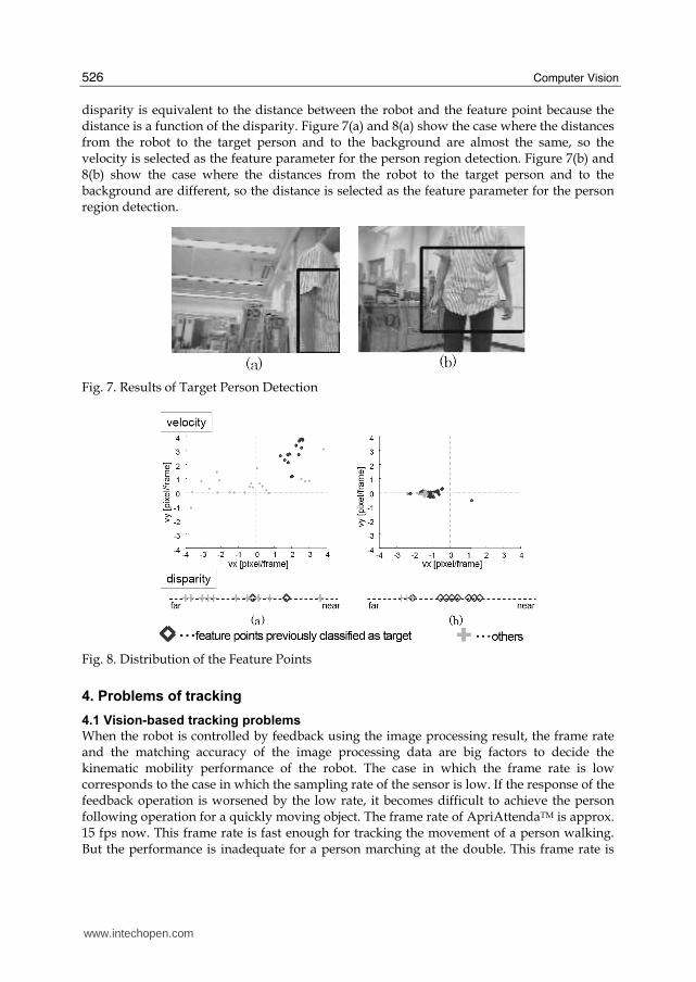
disparity is equivalent to the distance between the robot and the feature point because the distance is a function of the disparity. Figure 7(a) and 8(a) show the case where the distances from the robot to the target person and to the background are almost the same, so the velocity is selected as the feature parameter for the person region detection. Figure 7(b) and 8(b) show the case where the distances from the robot to the target person and to the background are different, so the distance is selected as the feature parameter for the person region detection.
Fig. 7. Results of Target Person Detection
Fig. 8. Distribution of the Feature Points
4. Problems of tracking
4.1 Vision-based tracking problems
When the robot is controlled by feedback using the image processing result, the frame rate and the matching accuracy of the image processing data are big factors to decide the kinematic mobility performance of the robot. The case in which the frame rate is low corresponds to the case in which the sampling rate of the sensor is low. If the response of the feedback operation is worsened by the low rate, it becomes difficult to achieve the person following operation for a quickly moving object. The frame rate of ApriAttendaTM is approx. 15 fps now. This frame rate is fast enough for tracking the movement of a person walking. But the performance is inadequate for a person marching at the double. This frame rate is
www.intechopen.com

Person Following Robot with Vision-based and Sensor Fusion Tracking Algorithm
527
decided by the trade-offs of the resolution and CPU performance etc. Moreover, the delay (latency) of the information transmission from the sensor input to the movement output also has a big influence on the kinematic performance. The system design that reduces this delay is needed too, because it is an important factor related to the content of the next frame for the image data processing in the vision-motion cooperative system. In the visual tracking, the result of the image data processing greatly influences subsequent operation. To begin with, this is one of the most important factors determining whether the tracking object is found accurately. However, even when it keeps detecting the object well, the person following operation might be influenced harmfully by other factors. The aimed direction of the tracking center wobbles when it recognizes only part of the tracking object or included the surroundings of the object, and this wobble becomes a serious problem when real motion is generated. Moreover, when distance information is measured by using the stereo disparity, it is necessary to extract the pair of the same feature point from pictures taken by right and left cameras simultaneously. If another feature point is chosen, a value that is greatly different from an actual distance will be calculated. But even if the process of matching works well, a big error margin will be calculated when the detection accuracy is bad. These wobbles and errors can be reduced by time-average processing such as by low-pass filters. However, the person following response will deteriorate according to the time delay at that time. Because the deterioration of the person following motion performance in the movement system is related to the success or failure of the subsequent image processing, it cannot be disregarded. When tracking is performed only in the stationary camera image, the above-mentioned characteristic is less important. These are new problems in a visual tracking servo motion control system that cooperates with its own movement. On the other hand, there are some problems concerning the camera sensor. Because the camera sensor captures scenery in angle of view as discrete information in each pixel, the area size in real space that one pixel covers increases as the distance in vision becomes greater, that is, sensor resolution decreases. The above-mentioned characteristic in the stereovision system means that a pixel shift on the image of the far object becomes a big discrete distance jump. This is a problem related to the hardware, so even if the best detection result can be obtained by the image processing, that problem will not be solved. The distance up to about 5m can be resolved in QQVGA (160x120 pixel) image that ApriAttendaTM uses, and the discretization error margin at this time becomes several ten centimeters at the maximum. To decrease the discretization error margin easily, it is only necessary to improve the resolution of the camera, that is, enlarge the size of camera image. However, in this case, a serious trade-off exists. Processing of a large-size image data imposes a huge CPU cost, which causes the frame rate to decrease, and, as a result, the kinematic performance of the robot worsens. From the viewpoint of precise distance measurement, use of another sensor such as an LRF is preferable to using a stereo camera. The measurement feature of the stereo camera and the laser sensor is shown in the following graphs. The graph shows the distance (Fig.9) and direction (Fig.10) from robot to person with the robot coordinate system when tracking a moving person. The method of tracking with the laser sensor is described below. The person following motion function of the robot is nullified in this experiment. Moreover, note that the true position information is not included in these graphs. However, the calibration has been done respectively beforehand, and the tracking result has been collated with a true value. In Fig.9, in the stereo camera distance data, the influence of the quantization of the image in the circled area "B" is found
www.intechopen.com

Computer Vision
528
besides the error that originates in the failure at the feature point matching in the area "A". For the direction element, almost the same measurement result as LRF is obtained. One reason for this result is thought to be that the resolution that originates in the image size and the angle of view of the camera and the scanning resolution of LRF used in this experiment are almost equal. Additionally, it can be found that the directional element information data of the camera is fluctuating overall more than that of LRF in Fig.10. The reason of this phenomenon is thought to be the above mentioned wobble of the tracking center that is originated from the feature point on the tracking target.
Camera Data
A
B
LRF Data
Camera Data
A
B
LRF Data
Fig. 9. Person Tracking Result for Robot-Person Distance [m]
Fig. 10. Person Tracking Result for Robot-Person Horizontal Direction [rad]
4.2 LRF tracking problems
Recently, a Laser Range Finder (LRF) capable of radially measuring straight-line distance in one plane has been miniaturized, and so it can be mounted on a robot easily. The directivity of the LRF is very strong and its accuracy and resolution are also high compared with the
www.intechopen.com

Person Following Robot with Vision-based and Sensor Fusion Tracking Algorithm
529
ultrasonic sensor, the infrared rays sensor, etc. Good use has been made of these characteristics of the LRF, and many researchers apply LRF to person detection and tracking operations. For instance, there are person detection and a tracking technique that extract the shape of a human's leg and the movement pattern from LRF measurement information and use it. The candidate shape of a human's leg is picked out from LRF data and the truth is judged by searching for the circle pair that has the size of leg section, and using the pattern match with the leg appearance movement model. Lee extracts the set of the LRF detection points based on a dynamic feature from the time series of data, and detects a pair that suits the person's walking step pattern and the leg size from the sets, and finally concludes that the pair is human and continues tracking it (Lee et al., 2006). Okusako detects the person's position by the block match with the template of typical scanning shape of the leg observed during walking (Okusako et al., 2006). However, many problems remain concerning the person following. Using such techniques, it is difficult to detect the sets of leg shape and decide a pair of legs when two or more people are adjacent. Moreover, the movements of actual people vary. The possibility of confusing various movements such as cut back, side step walking, turning around the place, pivot turning, skip, and movements similar to dance step with the usual movement is incontrovertible. A movement model covering all these possibilities will be complex and huge. It is also a problem that the feature information on which these methods rely is not general. For instance, if the person wears a long skirt or coat, these methods using the leg shape information do not function well. In addition, when the tracking object is a child, there is a possibility that the expected leg shape cannot be detected because the scanning position is different from in the case of an adult. Moreover, the detection of a person carrying luggage might deviate from the model. Moreover it is invalid for a person using assistant apparatus such as a wheelchair. As mentioned above, this technique has many restrictions concerning the state of a tracked target. On the other hand, it is clear that a trade-off exists: the lower the recognition condition set, the higher the rate of misidentification. In the case we envision, namely, that of the service robot acting in an environment in which it coexists with humans, using only LRF to track the person is insufficient. In a general environment in which the service robot acts, the situation in which the tracking object is completely concealed by another object irrespective of the robot’s own behavior must be considered. Using only LRF information, it is almost impossible to re-detect a tracking target once it has been completely lost. For this case, it is effective to employ a method in which another sensor's information, such as camera image, is also used.
5. Vision – LRF sensor fusion tracking
5.1 Consideration of best configuration of sensor fusion system
Generally, when thinking about the sensor fusion of the camera and LRF, the roles of different sensors are clearly distinguished; for instance, to detect the object with the camera, and to measure the distance to the object with LRF. Another method has been devised in which, first, the target is tracked by the image data processing or the LRF leg detection, and next, the normal continuance of the tracking is confirmed by collating the tracking results. However, in the former method the complementation of each defect is insufficient. For instance, LRF may detect the distance on this side wrongly. In the latter method, logical multiplication processing is executed. It will decrease the misidentification rate but not lead to the extension of the continuance time of the tracking.
www.intechopen.com

Computer Vision
530
It is necessary to consider each merit and weak point of the camera and LRF. From the viewpoint of recognition, the image data processing to obtain a lot of feature information such as color, print pattern, texture, and stereo distance is generally dependable and stable. LRF has high possibility of misdetection and misidentification depending on the situation. However, sufficient tracking can be done by LRF alone, using a simple algorithm such as the neighborhood area search based on time continuousness at object position without the high characteristic feature information such as a body shape etc. in an open space where there is no fear of misidentification. Additionally, it is attractive that it is possible to correspond to various movements of people, large range of body height, many kinds of clothes, and assistant apparatus such as wheelchairs for such simple logic. Moreover, in the case of this logic, there is no problem even if the root of the leg or the trunk of the body is scanned. So it is expected that a steadier positional detection result is obtained because the influence of intense movement of the tips of legs is decreased. On the other hand, from the viewpoint of accuracy of information, LRF detection is overwhelmingly excellent. It becomes an important factor for quick follow motion. This is not limited to the distance element, and also applies to the direction element. Even if the camera resolution is the same level as LRF, the image data processing might hinder the movement compared with the LRF case. Because, generally, the image processing needs to continue tracking, repeatedly detecting and updating the feature points, the wobble and the drift of the tracking center are apt to stand out. The characteristics of the sensors are shown below.
occlusion accuracy
hum an detect
and identify
constraint
C am era good bad good norm al
LRF (use leg info.) bad good norm al bad
LRF (no leg info.) bad good bad good
Table 2. Characteristics of Sensors
We can use the camera system for human detection, whereas tracking using LRF only is problematic. The necessity of the LRF tracking method using leg shape information becomes lower in a system where the camera can be used as in the case of ApriAttendaTM. And the general-purpose LRF tracking algorithm is more effective on this system. Thus, according to the situation, the roles of each sensor should be different. So, it is important to develop a strategy based on consideration of the configuration of the entire system. The rate of misidentification will be decreased by a strategy that takes logical multiplication of each sensor's information. If it is possible, we want to integrate and use the obtained information widely by taking the logical add, for example. However, there is a possibility of adopting the error value through such integration, and fatal misidentification may be generated. If there is an index that judges whether the sensor information can be used for the tracking, we can improve the overall performance by switching sensor information according to the state of the environment. So, we pay attention to the surrounding congestion situation in the space where the tracking target exists and design a tracking system that adopts the concept of sensor fusion such that the fusion rate changes depending on the congestion degree. When the surrounding space condition is not-congestion, the sensor fusion system gives weight to LRF information. And it shifts to the camera information from LRF when the surroundings are congested.
www.intechopen.com
Person Following Robot with Vision-based and Sensor Fusion Tracking Algorithm
531
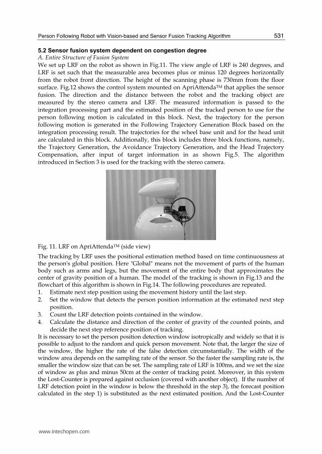
5.2 Sensor fusion system dependent on congestion degree A. Entire Structure of Fusion System We set up LRF on the robot as shown in Fig.11. The view angle of LRF is 240 degrees, and LRF is set such that the measurable area becomes plus or minus 120 degrees horizontally from the robot front direction. The height of the scanning phase is 730mm from the floor surface. Fig.12 shows the control system mounted on ApriAttendaTM that applies the sensor fusion. The direction and the distance between the robot and the tracking object are measured by the stereo camera and LRF. The measured information is passed to the integration processing part and the estimated position of the tracked person to use for the person following motion is calculated in this block. Next, the trajectory for the person following motion is generated in the Following Trajectory Generation Block based on the integration processing result. The trajectories for the wheel base unit and for the head unit are calculated in this block. Additionally, this block includes three block functions, namely, the Trajectory Generation, the Avoidance Trajectory Generation, and the Head Trajectory Compensation, after input of target information in as shown Fig.5. The algorithm introduced in Section 3 is used for the tracking with the stereo camera.
Fig. 11. LRF on ApriAttendaTM (side view)
The tracking by LRF uses the positional estimation method based on time continuousness at the person's global position. Here "Global" means not the movement of parts of the human body such as arms and legs, but the movement of the entire body that approximates the center of gravity position of a human. The model of the tracking is shown in Fig.13 and the flowchart of this algorithm is shown in Fig.14. The following procedures are repeated. 1. Estimate next step position using the movement history until the last step. 2. Set the window that detects the person position information at the estimated next step
position. 3. Count the LRF detection points contained in the window. 4. Calculate the distance and direction of the center of gravity of the counted points, and
decide the next step reference position of tracking. It is necessary to set the person position detection window isotropically and widely so that it is possible to adjust to the random and quick person movement. Note that, the larger the size of the window, the higher the rate of the false detection circumstantially. The width of the window area depends on the sampling rate of the sensor. So the faster the sampling rate is, the smaller the window size that can be set. The sampling rate of LRF is 100ms, and we set the size of window as plus and minus 50cm at the center of tracking point. Moreover, in this system the Lost-Counter is prepared against occlusion (covered with another object). If the number of LRF detection point in the window is below the threshold in the step 3), the forecast position calculated in the step 1) is substituted as the next estimated position. And the Lost-Counter
www.intechopen.com

Computer Vision
532
counts up. The Lost-Counter is initialized to zero when an effective LRF detection point is detected in the window. As a result, it is possible to endure the momentary occlusion. If the Lost-Counter reached a threshold value, it is judged that the system cannot detect the pursued object again. At this time, the system exits the tracking motion mode, and changes the motion mode to another mode. Various methods are employed in other modes. For instance, the robot wanders in the space and searches for the following target again based on the image template.
Sensor Fusion
Estimated Target Position
(Sensor Fusion Result)
Person Following
Trajectory Generation
Tracking Motion Trajectory
for Robot Base (Wheel Unit)
Tracking Motion Trajectory
For Robot Head (Camera Mount Unit)
Base (Wheel Unit)
Motion Control System
Head (Mount Unit)
Motion Control System
Camera
LRF
Target Information:
珙on Robot Base Coordinate珩
Direction, Distance to the Human
Target
(Human)
+
+
+
+
-
-
Robot Environment
Robot Base
Position
Robot Head
Position
Target Information:
珙on Robot Camera Coordinate珩
Direction, Distance to the Human
Fig. 12. Motion Control System of ApriAttendaTM Based on Sensor Fusion Data
Wall
Column
Mobile Robot
Another Person,Obstacle
LRF
:LRF Detecting Point
Penultimate Step Estimated
Person Position
Last Step Estimated Person Position
This Step Pre-Es timated
Person Position
Search WindowThis Step Fixed Estimated
Person Position
Next Step Pre-Estimate
Person Position
Last Step Search Window
Adopted LRF Detecting
Points to Es timate
Person Position
Target Person
Wall
(1)
(2)
(3)
(4)
Wall
Column
Mobile Robot
Another Person,Obstacle
LRF
:LRF Detecting Point
Penultimate Step Estimated
Person Position
Last Step Estimated Person Position
This Step Pre-Es timated
Person Position
Search WindowThis Step Fixed Estimated
Person Position
Next Step Pre-Estimate
Person Position
Last Step Search Window
Adopted LRF Detecting
Points to Es timate
Person Position
Target Person
Wall
(1)
(2)
(3)
(4)
Fig. 13. Model of Person Tracking Algorithm Using LRF Data
www.intechopen.com

Person Following Robot with Vision-based and Sensor Fusion Tracking Algorithm
533
Pre-Estimate Next Person Position
from Before Person Estimated Position
Set Search Window around
the Pre-Estimated Position
Select LRF Detecting Point in
the Search Window
Does Detection Point
Exist in the Window?
Set Pre-Estimated Position as This
Step Estimated Person Position
and Increase Lost Counter
Is Lost-Counter
Saturated?
Shift Tracking Lost Sequence
珙Interruption of tracking process etc.珩
Yes
Yes
No
No
2.
1.
3.
4. Calculate Center of Gravity Point for
the Selected LRF Detecting Point and
Fix the Gravity Point as This Step
Estimated Person Position
Fig. 14. Flowchart of Person Tracking Algorithm Using LRF Data
B. Sensor Fusion Method The rate changeable sensor fusion system in which the integrated ratio of vision and LRF information changes depending on the environment state around the tracking target is designed. It is expressed as shown in Fig.15. This processing is executed in the Sensor Fusion block in the system shown in Fig.12. The congestion situation around the tracking target is used as a surrounding environment status that contributes to the fusion ratio "W". And the congestion degree "C" is set as an index that expresses this congestion situation. W and C are the real numbers that take values from 0 to 1. W and C are defined by expression (2). The sensor fusion process shown by expression (1) is executed using these values. Here, "n" in expression (2) is prepared to make the fusion rate nonlinear to the congestion degree.
This time the value is set to n=0.4 in the experiment based on experience. "θC" and "θL" are the direction information that can be obtained from the vision system and the LRF system.
"dC" and "dL" are the distance information that can also be obtained. "θ" and "d" are the information of the direction and the distance to generate the following motion trajectory.
Camera Info.
LRF Info.
Sensor Fusion Tracking Info.
Environment State
C : Congestion Degree
Direction : θC
W : Fusion Rate
Distance : d C
Direction : θL
Distance : d L
Tracking Direction : θ
Tracking Distance : d
Camera Info.
LRF Info.
Sensor Fusion Tracking Info.
Environment State
C : Congestion Degree
Direction : θC
W : Fusion Rate
Distance : d C
Direction : θL
Distance : d L
Tracking Direction : θ
Tracking Distance : d
Fig. 15. Rate-Changeable Environmental Adaptive Sensor Fusion Model
www.intechopen.com

Computer Vision
534
( )
( )1
1
L C
L C
W W
d d W d W
θ θ θ= ⋅ + ⋅ −= ⋅ + ⋅ − (1)
nW C= (2)
max
Cong
Cong
NC
N= (3)
The congestion degree "C" is defined by the expression (3). This is illustrated in Fig.16. The
congestion observation window area is prepared around the person position detection
window that used LRF tracking. NmaxCong is the total number of times the scanning laser
passes over this area. NCong is defined as the number of times the scanning laser is able to
observe the detection point in the congestion observation window. Here, the congestion
observation window is defined such that the area of the window doesn't include the person
position detection window area. Therefore, the congestion degree becomes 0 when no other
object exists around the tracking target, and it approaches 1 when the number of other
objects around the target increases.
LRF
Scanning Laser
Environment Congestion
Search Window
Tracking Target
Search Window
LRF
Scanning Laser
Environment Congestion
Search Window
Tracking Target
Search Window
Fig. 16. Definition of Environmental Congestion
C. Person Following Motion An experiment of person following motion was performed using ApriAttendaTM mounted
with this sensor fusion method. From this experiment, in open space, it was confirmed that
the robot can follow a person smoothly who moves quickly and randomly. In the
experiment, the person moves to the translational direction of the robot at a maximum
speed of about 1.2 m/s, and to the rotational direction of the robot at a maximum speed of
about 5.0 m/s at a point of 1.5m from the robot.
www.intechopen.com

Person Following Robot with Vision-based and Sensor Fusion Tracking Algorithm
535
Fig. 17. Fast Person Following Motion
When the person passes over an obstacle in the neighborhood as illustrated in Fig.18, the robot can continue following without losing sight of the person. At this time, the internal state of the robot changes as shown in Fig.19. It is understood that the direction element of the follow reference (heavy-line) smoothly changes from LRF information (deep-color, thin-line) to camera information (light-color, thin-line) according to the congestion degree of the environment (dotted-line) in the figure. We can also understand that the tracking is continued normally from the camera shot shown in Fig.20.
Wall(Room Partition)
Walking Person
Person Following
Robot
1.2 [m]
( Velocity : approx.0.8~1.0[m/s] )
nearer than 50[cm]
Fig. 18. Experimental Situation: Walking Person Passes near Another Object
Fig. 19. Person Direction and Congestion Degree in the case of Success Tracking
www.intechopen.com

Computer Vision
536
63.5[s] 64.0[s] 64.3[s]
64.8[s] 65.1[s] 65.4[s]
Fig. 20. Robot Camera View during Tracking (Person Passes near Another Object)
In addition, the robot can continue following normally without losing sight of the followed
object in the case of the meeting and parting motion (pseudo crossing motion) involving two
people as illustrated in Fig.21. And Fig.22 shows the scenery of the experiment of Fig.21. In
this experiment, two people who have approached have instantaneously exchanged a rate
vector, at the time of the encounter. This motion of the target results in a high probability of
misidentification when the robot refers only to the positional history of the target measured
by LRF. However, the following motion can be perfectly continued in this system where the
designed sensor fusion is mounted. On the other hand, we have confirmed that the robot
can follow the target correctly, distinguishing the situation accurately without guessing
wrong as to the general cross-motion of the target, too.
Because the above-mentioned movements, such as the nondirectional movement, the fast
movement, the crossing and pseudo-crossing motion with other people, and the occlusion
are events that occurs naturally in the human coexistence space, it is very important for the
service robot to have these person following abilities in these situations.
Person Following
Robot
Walking Person (Following Target)
( Velocity : approx.0.8~1.0[m/s] )
Walking Person (Another Target)
( Velocity : approx.0.8~1.0[m/s] )
Fig. 21. Experimental Situation: Pseudo Crossing Motion (Two People Walking Meet and Part)
www.intechopen.com

Person Following Robot with Vision-based and Sensor Fusion Tracking Algorithm
537
(1) (2) (3)
(4) (5) (6)
Fig. 22. Experimental Result for Pseudo Crossing Motion
6. Conclusion
The person following robot ApriAttendaTM equipped with a stereo camera and Vision System and LRF is introduced. ApriAttendaTM has the Vision-Based Tracking system and the Vision-Based Motion Control system. ApriAttendaTM can do the person following motion using the tracking information. Moreover, ApriAttendaTM used LRF as another sensor for the tracking performance gain. The respective problems of the vision and LRF tracking systems are pointed out and an improvement method based on the idea of the Vision-LRF Sensor Fusion system is proposed. One feature of this new system is that the fusion rate changes depending on the congestion information of the environment. The experimental movement results of applying these systems to ApriAttendaTM are reported. The efficiency of the proposed method is confirmed by the experiment. As discussed here, efforts to achieve an advanced application using sensors independently are subject to an unavoidable limit. So, a system design integrating information from two or more types of sensor is required. Because the vision data containing abundant information plays a key role in the complex system, further development of the vision system is desirable.
7. References
Cielniak, G.; Treptow, A. & Duckett T. (2005). Quantitative Performance Evaluation of a People Tracking System on a Mobile Robot, Proceedings of ECMR05 (2nd European Conference on Mobile Robots), Ancona, Italy, September 2005
Hirai, N. & Mizoguchi, H. (2003). Visual Tracking of Human Back and Shoulder for Person Following Robot, Proceedings of the 2003 IEEE/ASME International Conference on Advanced Intelligent Mechatronics (AIM2003), pp. 527-532, Kobe, Japan, July 2003
Kobilarov, M.; Sukhatme, G.; Hyams, J. & Batavia, P. (2006). People tracking and following with mobile robot using an omnidirectional camera and a laser, Proceedings of the
www.intechopen.com

Computer Vision
538
2006 IEEE International Conference on Robotics and Automation (ICRA2006), pp. 557-562, Orlando, Florida, May 2006
Kwon, H.; Yoon, Y.; Byung, J.; Park, B. & Kak, C.A. (2005). Person Tracking with a Mobile Robot using Two Uncalibrated Independently Moving Cameras, Proceedings of the 2005 IEEE International Conference on Robotics and Automation (ICRA2005), pp. 2888-2894, Barcelona, Spain, April 2005
Lee, J.; Tsubouchi, T.; Yamamoto, K. & Egawa, S. (2006). People Tracking Using a Robot in Motion with Laser Range Finder, Proceedings of the 2006 IEEE/RSJ International Conference on Intelligent Robots and Systems (IROS2006), pp. 2396-2942, Beijing, China, October 2006
Matsuhira, N.; Ozaki, F.; Ogawa, H.; Yoshimi, T. & Hashimoto, H. (2005a). Expanding Practicability of ApriAlpha in Cooperation with Networked Home Appliances, Proceedings of IEEE Workshop on Advanced Robotics and its Social Impacts (ARSO '05), pp. 254-259, Nagoya, Japan, June 2005
Matsuhira, N.; Ogawa, H.; Yoshimi, T. & Mizoguchi, H. (2005b). Development of Life Support Robots that Coexist in Harmony with People, Proceedings of the 36th International Symposium on Robotics (ISR2005), TU 4H-5, Tokyo, Japan, November 2005
Okusako, S. & Sakane, S. (2006). Human tracking with a mobile robot using a laser range-finder. Journal of Robotics Society of Japan, Vol.24, No.5, (July 2006) pp.605-613, (in Japanese)
Ozaki, F. (2003). Open Robot Controller Architecture, Workshop on Middleware Technology for Open Robot Architecture, 2003 IEEE/ASME International Conference on Advanced Intelligent Mechatronics (AIM2003), Kobe, Japan, July 2003
Sato, H; Hashimoto, H; Suzuki, K. & Ozaki, F. (2005). A Versatile Multimedia Front-end Processing Board for Handling Visual and Acoustic Signals Concurrently, Robotics and Mechatronics Conference 2005 (Robomec2005), 2P1-N-053, Kobe, Japan, June 2005 (in Japanese)
Schlegel, C.; Illmann, J.; Jaberg, H.; Schuster, M. & Wörz, R. (1998). Vision Based Person Tracking with a Mobile Robot, Proceedings of the 9th British Machine Vision Conference, pp. 418-427, Southampton, UK, 1998
Sidenbladh, H.; Kraqic, D. & Christensen, H.I. (1999). A Person Following Behaviour for a Mobile Robot, Proceedings of the 1999 IEEE International Conference on Robotics and Automation (ICRA1999), pp. 670-675, Detroit, Michigan, May 1999
Yoshimi, T.; Matsuhira, N.; Suzuki, K.; Yamamoto, D.; Ozaki, F.; Hirokawa, J. & Ogawa, H. (2004). Development of a Concept Model of a Robotic Information Home Appliance, ApriAlpha, Proceedings of the 2004 IEEE/RSJ International Conference on Intelligent Robots and Systems (IROS2004), pp.205-211, Sendai, Japan, October 2004
Yoshimi, T.; Nishiyama, M.; Sonoura, T.; Nakamoto, H.; Tokura, S.; Sato, H.; Ozaki, F.; Matsuhira, N. & Mizogushi, H. (2006). Development of a Person Following Robot with Vision Based Target Detection, Proceedings of the 2006 IEEE/RSJ International Conference on Intelligent Robots and Systems (IROS2006), pp. 5286-5291, Beijing, China, October 2006
www.intechopen.com

Computer VisionEdited by Xiong Zhihui
ISBN 978-953-7619-21-3Hard cover, 538 pagesPublisher InTechPublished online 01, November, 2008Published in print edition November, 2008
InTech EuropeUniversity Campus STeP Ri Slavka Krautzeka 83/A 51000 Rijeka, Croatia Phone: +385 (51) 770 447 Fax: +385 (51) 686 166www.intechopen.com
InTech ChinaUnit 405, Office Block, Hotel Equatorial Shanghai No.65, Yan An Road (West), Shanghai, 200040, China
Phone: +86-21-62489820 Fax: +86-21-62489821
This book presents research trends on computer vision, especially on application of robotics, and on advancedapproachs for computer vision (such as omnidirectional vision). Among them, research on RFID technologyintegrating stereo vision to localize an indoor mobile robot is included in this book. Besides, this book includesmany research on omnidirectional vision, and the combination of omnidirectional vision with robotics. Thisbook features representative work on the computer vision, and it puts more focus on robotics vision andomnidirectioal vision. The intended audience is anyone who wishes to become familiar with the latest researchwork on computer vision, especially its applications on robots. The contents of this book allow the reader toknow more technical aspects and applications of computer vision. Researchers and instructors will benefit fromthis book.
How to referenceIn order to correctly reference this scholarly work, feel free to copy and paste the following:
Takafumi Sonoura, Takashi Yoshimi, Manabu Nishiyama, Hideichi Nakamoto, Seiji Tokura and NobutoMatsuhira (2008). Person Following Robot with Vision-based and Sensor Fusion Tracking Algorithm,Computer Vision, Xiong Zhihui (Ed.), ISBN: 978-953-7619-21-3, InTech, Available from:http://www.intechopen.com/books/computer_vision/person_following_robot_with_vision-based_and_sensor_fusion_tracking_algorithm