Embed Size (px)
Citation preview
Personal Air Vehicle Exploration (PAVE)
Mark D. MooreNASA Langley Research Center

PAVE Introduction
Current Solution: A fun, expensive hobby with some usefulness, but not nearly enough.
HERSHIS
= +Future Solution: Door to door personal transportation, a blending of car and plane.
After being exposed to cars for 100 years, can we look into the future and understand the mission, concepts, and technologies for higher capacity and faster solutions?
3
PAVE Overview
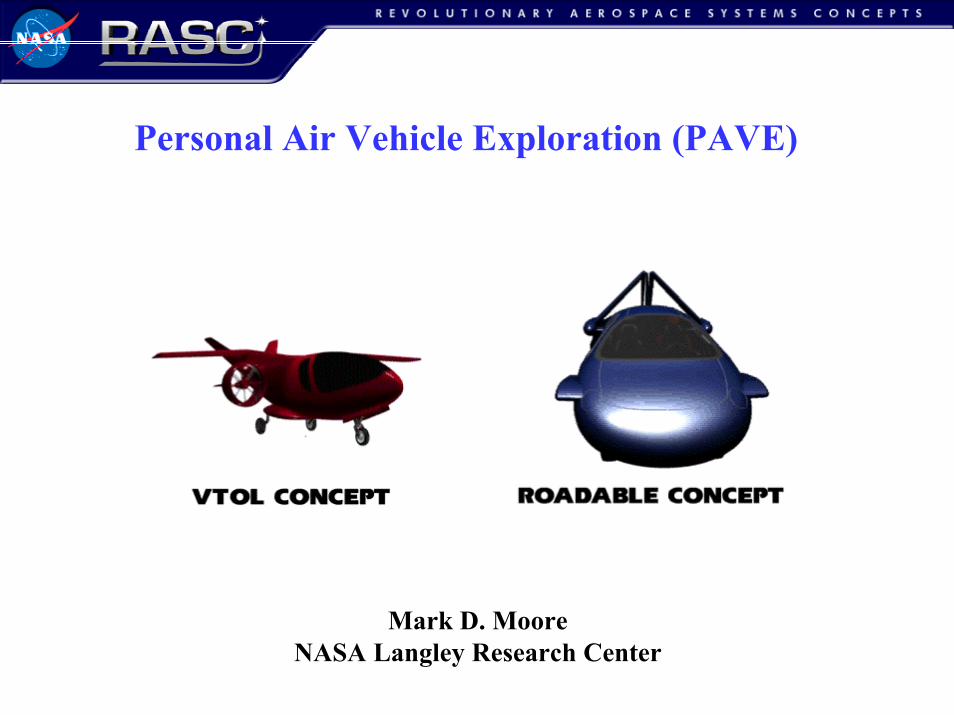
MissionDoor to door personal travel (a system solution involving air and ground)
• Live, shop, entertain, work... where you want, when you wantImprovements in lifestyle and benefits for entire U.S. population
How is PAVE different from prior efforts?
Small companies have been trying to do this for 50 years• Minimal facilities, funding, expertise, technology development
No prior system study performed• Design by constraint, requirement matrix, evaluation by metric
How is PAVE revolutionary?PAVE offers large initial, quantifiable benefits
• Mobility, Capacity, AccessibilityPAVE offers future benefits of a paradigm shift
• Distributed network redundancy, Infrastructure investment, etc...
-More-
-More-
-More-
-More-
4
Comparison to Enterprise Objectives
PAVE addresses many Aerospace Technology Enterprise objectives:
• Increased Mobility
“enable people to travel faster and farther, anywhere, anytime”
• Increased Capacity - both at hub and spoke, and on highways
• Increase Safety, Reduce Emissions, Reduced Noise
• Pioneer Technology Innovation
• Commercialize Technology
PAVE meets additional NASA and Langley critical needs
• SATS is developing the air highways, PAVE is developing the air cars.
• NASA can invest where there is no near term ROI, with relatively low cost.
• NASA researchers believe we can make a difference…and are motivated.
• High visibility, high risk, high payoff
5
Study Objective and ApproachEstablish a foundation– Review prior concepts and current relevant technologies.– Extract requirements, missions, and constraints– Establish metrics as a basis for comparison.– Define potential infrastructure scenarios.– Develop baseline vehicles with current technology .
Explore the design space– Define, establish, and integrate synergistic technologies (2015 TRL 6).– Develop advanced concepts utilizing physics based methods.– Compare concepts to reference baselines, each other, and alternate travel modes.
Determine technology investment approach– Show technology sensitivities and gaps for the various mission concepts.– Show assumption sensitivities to understand the elasticity of the design space.– Present the study results in a highly interactive, intuitive and visual format.
6
PAVE Technologies (2015 TRL 6)
SATS Airspace Control, Avionics, and Manufacturing (2007) -More-
Propulsion• Reciprocating engines -More-
• Turbofan and turboshaft engines -More-
• Distributed propulsion mini-engines systems -More-
• Dual mode air/ground power transmission system -More-
• Electric propulsion -More-
• Noise reduction (shielding, quiet fans, acoustic damping)Aerodynamics
• Circulation Control -More-
Aero-Propulsive Systems and Controls• Distributed inlet coupled to wing boundary layer control -More-
• Circulation Control Channel Wing -More-
• Multi-Gas Generator Fan / Circulation Control Nacelle -More-
Structures• Highly constrained span wing systems -More-
• Ultra lightweight structures -More-
• Failsafe articulating structures with active sensors
7
PAVE Study Team
NASA• LaRC Systems Analysis• LaRC Configuration Aerodynamics Branch• GRC Systems Analysis• Ames Systems Analysis
Partners• Boeing Long Beach• Virginia Polytechnic Insititute • Cal Poly San Luis Obispo• Georgia Tech
Leveraging Programs• AGATE, SATS, uSATS, GAP Programs• LaRC Virtual Flap Circulation Control Morphing Workpackage• LaRC Circulation Control Channel Wing C&I • LaRC Distributed Propulsion Concept C&I• DARPA Micro-engine Program
8
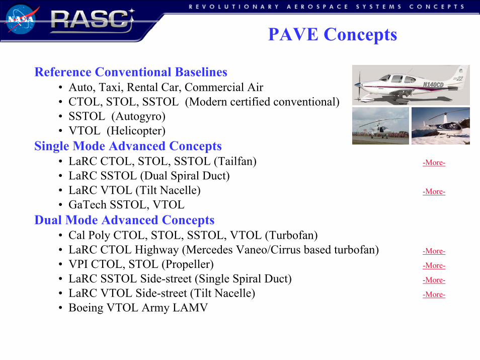
PAVE Concepts
Reference Conventional Baselines• Auto, Taxi, Rental Car, Commercial Air• CTOL, STOL, SSTOL (Modern certified conventional)• SSTOL (Autogyro)• VTOL (Helicopter)
Single Mode Advanced Concepts• LaRC CTOL, STOL, SSTOL (Tailfan) -More-
• LaRC SSTOL (Dual Spiral Duct)• LaRC VTOL (Tilt Nacelle) -More-
• GaTech SSTOL, VTOLDual Mode Advanced Concepts
• Cal Poly CTOL, STOL, SSTOL, VTOL (Turbofan) • LaRC CTOL Highway (Mercedes Vaneo/Cirrus based turbofan) -More-
• VPI CTOL, STOL (Propeller) -More-
• LaRC SSTOL Side-street (Single Spiral Duct) -More-
• LaRC VTOL Side-street (Tilt Nacelle) -More-
• Boeing VTOL Army LAMV

9
PAVE Summary
Study• A cross-disciplinary and cross-cultural team has been organized• Several layers of infrastructure solutions considered (CTOL to VTOL) -More-
• Mission focus is on point to point travel, also some specialty missions• Common ground rules• Comparison based on relevant metrics (involving cost effectiveness)• Highly integrated designs require detailed physics based tools• Contractor and in-house results will be complete in December.Findings• Design constraints are defining the problem, not performance.• Utilization is a primary concern (addition of air-taxi and air-rental).• Poor performance of baselines, and availability of new synergistic technologies
make this mission appear fertile for major improvements with advanced designs.• Circulation control and distributed engine technologies are highly synergistic• Contacts with GM and Ford, possibility of joint workshop next spring.• Follow on work will provide detailed designs, technologies, and costing
as well as greater depth in top level systems benefits.
Backup Material
11
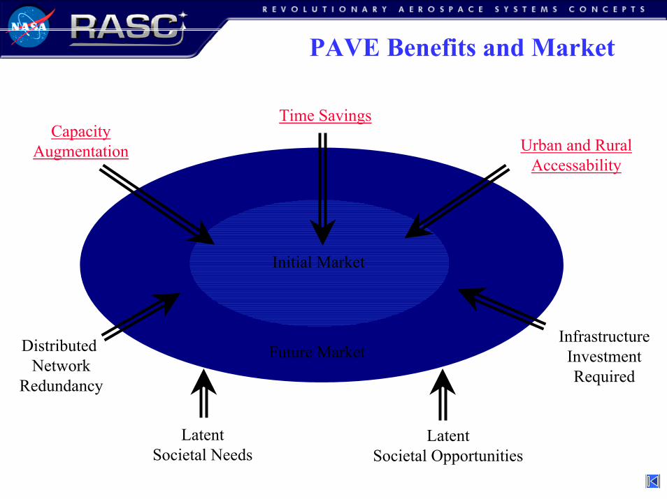
PAVE Benefits and Market
Initial Market
Future MarketDistributed Network
Redundancy
CapacityAugmentation Urban and Rural
Accessability
InfrastructureInvestmentRequired
Time Savings
LatentSocietal Needs
LatentSocietal Opportunities

12
PAVE Time Benefit
“…Time is the scarce commodity of the 21st century...”
20,00040,00060,00080,000
100,000120,000140,000160,000180,000200,000220,000240,000
1950 1960 1970 1980 1990 2000
Top 5%: +97%
Top 20%: +73%
Average: +30%
Average Income per HouseholdAdjusted for constant 1997 Dollars - Excluding long term stock sales
Source: Economic Policy Institute
4x speed is worth ~$68,000 /yr for top 5%
13
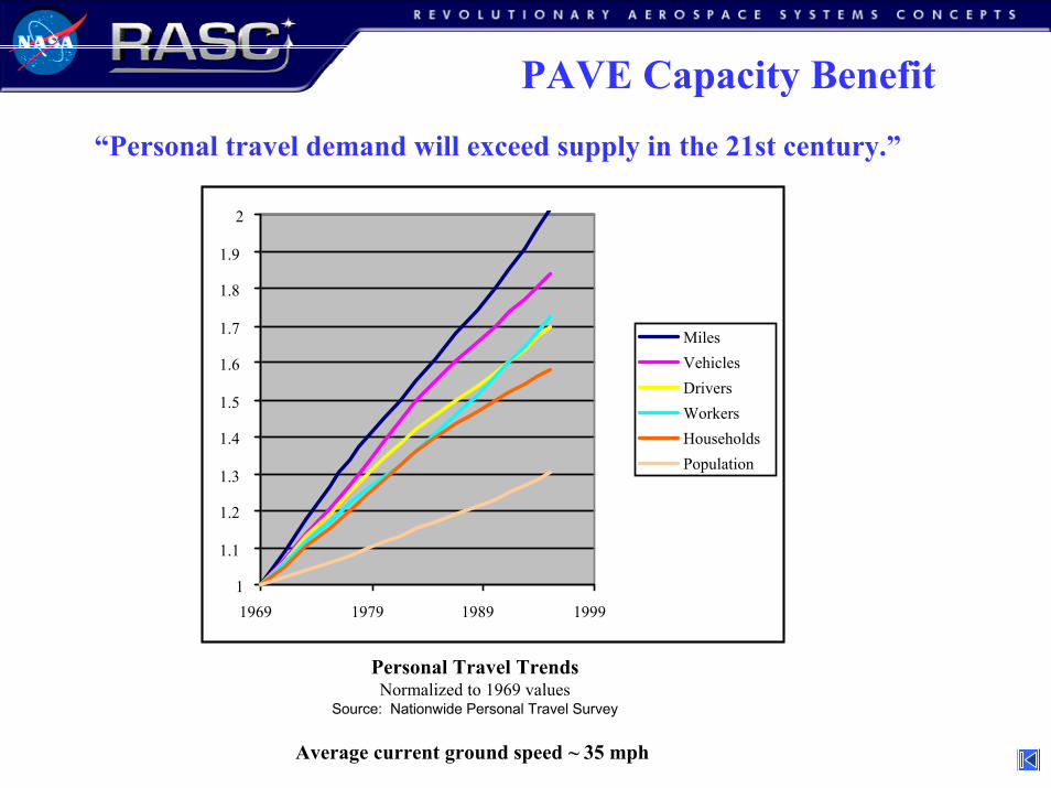
PAVE Capacity Benefit“Personal travel demand will exceed supply in the 21st century.”
1
1.1
1.2
1.3
1.4
1.5
1.6
1.7
1.8
1.9
2
1969 1979 1989 1999
MilesVehiclesDriversWorkersHouseholdsPopulation
Personal Travel TrendsNormalized to 1969 values
Source: Nationwide Personal Travel Survey
Average current ground speed ~ 35 mph

14
PAVE Mission
Improvements in lifestyle and benefits for entire U.S. population• Top 20% and 5% income bracket breaks even with vehicles of 4x speed at a cost of $200K to $500K.
• Rental and Air-taxi have a 5-10 fold utilization increase that permits average income bracket to benefit
• Aerial services, Package delivery, Police, Rescue, EMS, Border patrol, Military, Recon, Auto-Evac...
0
50
100
150
200
250
300
350
400
0 500 1000 1500 2000 2500
Great Circle Distance, nm
Fast Fast PAV’sPAV’s
HubHub--SpokeSpoke
Medium Medium PAV’sPAV’s
Highways
Range set byaverage small aircraftand auto ranges
-More-
Door to Door Travel Time by Mode

15
PAVE Mission
PAVE mission range captures over 90% of small aircraft departures
0
100
200
300
400
500
600
700
800
0
100
200
300
400
500
600
700
800
900
1000
1100
1200
1300
1400
1500
1600
1700
1800
1900
2000
More
Distance (nmi)
Freq
uenc
y
0
100
200
300
400
500
600
700
800
900
1000
0
100
200
300
400
500
600
700
800
900
1000
1100
1200
1300
1400
1500
1600
1700
1800
1900
2000
More
Distance (nmi)
Freq
uenc
y
Trip Distance DistributionSingle-Engine AircraftMulti-Engine Aircraft
Range = 400 at max speed, plus 45 min at best enduranceBladder limit of 2 hrs cruising at 250 kn, 4 hrs at 100 kn.Greater range than average auto (+ 50%)
16
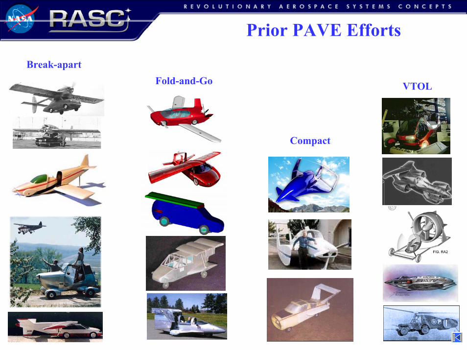
Prior PAVE Efforts
Break-apartFold-and-Go VTOL
Compact
F
17
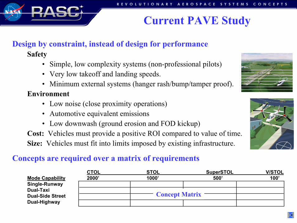
Current PAVE Study
Design by constraint, instead of design for performanceSafety
• Simple, low complexity systems (non-professional pilots)• Very low takeoff and landing speeds.• Minimum external systems (hanger rash/bump/tamper proof).
Environment • Low noise (close proximity operations)• Automotive equivalent emissions• Low downwash (ground erosion and FOD kickup)
Cost: Vehicles must provide a positive ROI compared to value of time.Size: Vehicles must fit into limits imposed by existing infrastructure.
Concepts are required over a matrix of requirements CTOL STOL SuperSTOL V/STOL
Mode Capability 2000’ 1000’ 500’ 100’Single-RunwayDual-TaxiDual-Side StreetDual-Highway
Concept Matrix

18
SATS Technologies
Highway in the Sky - HUD flight path
Synthetic Vision
Precision approach capability to runways
No control towers, radar, or approach lights
Internet of the air information systems
Near-all-weather operability
Self-separating & sequencing
Datalink / Databus / Database
Built-in terrain mapping and airspace avoidance
Lean Design / Lean Manufacturing
SATS Airspace Control, Avionics, and Manufacturing
19
PAVE Reciprocating Engines
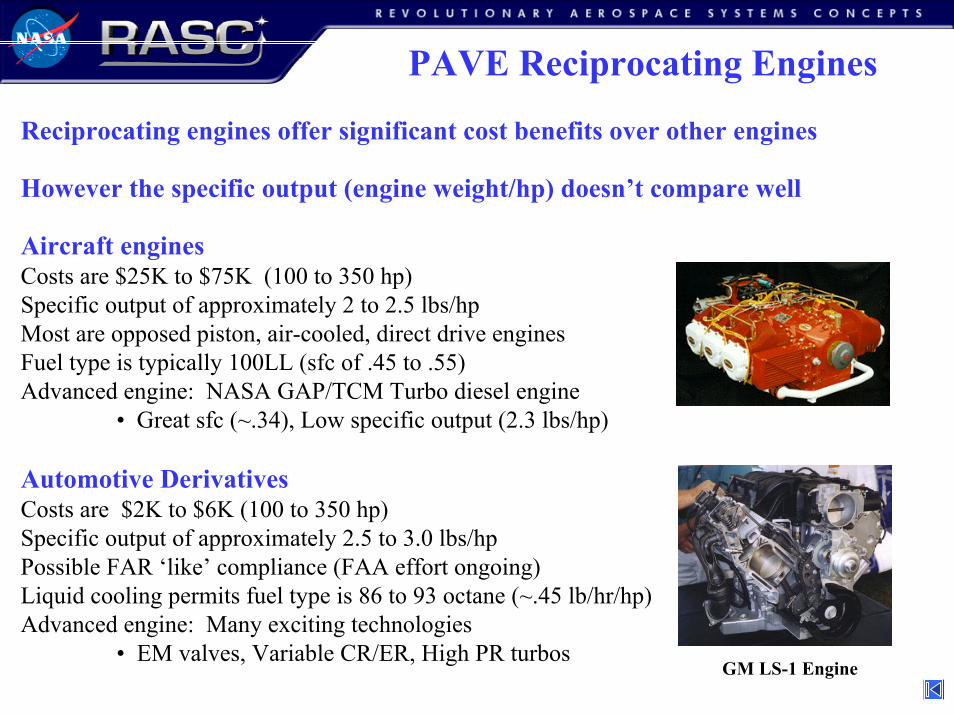
Reciprocating engines offer significant cost benefits over other engines
However the specific output (engine weight/hp) doesn’t compare well
Aircraft enginesCosts are $25K to $75K (100 to 350 hp)Specific output of approximately 2 to 2.5 lbs/hpMost are opposed piston, air-cooled, direct drive enginesFuel type is typically 100LL (sfc of .45 to .55)Advanced engine: NASA GAP/TCM Turbo diesel engine
• Great sfc (~.34), Low specific output (2.3 lbs/hp)
Automotive DerivativesCosts are $2K to $6K (100 to 350 hp)Specific output of approximately 2.5 to 3.0 lbs/hpPossible FAR ‘like’ compliance (FAA effort ongoing)Liquid cooling permits fuel type is 86 to 93 octane (~.45 lb/hr/hp)Advanced engine: Many exciting technologies
• EM valves, Variable CR/ER, High PR turbosGM LS-1 Engine
20
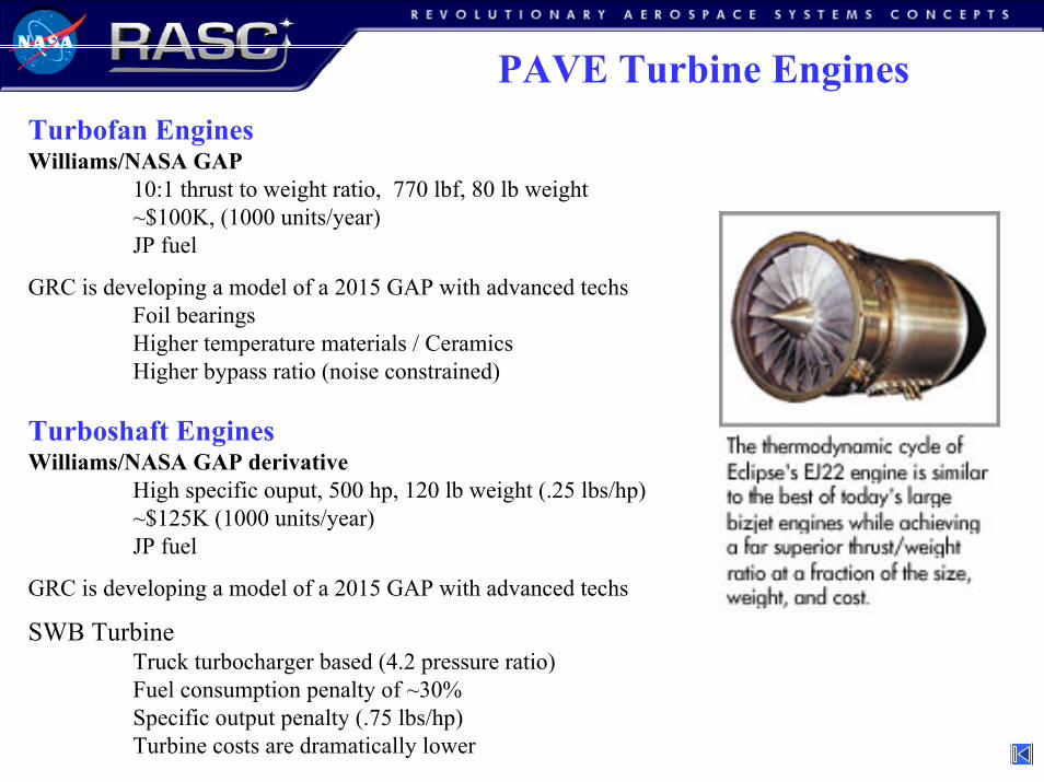
PAVE Turbine EnginesTurbofan EnginesWilliams/NASA GAP
10:1 thrust to weight ratio, 770 lbf, 80 lb weight~$100K, (1000 units/year)JP fuel
GRC is developing a model of a 2015 GAP with advanced techsFoil bearingsHigher temperature materials / CeramicsHigher bypass ratio (noise constrained)
Turboshaft EnginesWilliams/NASA GAP derivative
High specific ouput, 500 hp, 120 lb weight (.25 lbs/hp) ~$125K (1000 units/year)JP fuel
GRC is developing a model of a 2015 GAP with advanced techs
SWB TurbineTruck turbocharger based (4.2 pressure ratio)Fuel consumption penalty of ~30%Specific output penalty (.75 lbs/hp)Turbine costs are dramatically lower
21
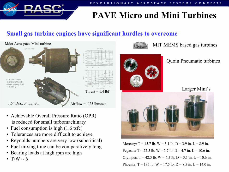
PAVE Micro and Mini Turbines
Small gas turbine engines have significant hurdles to overcome
MIT MEMS based gas turbines
1.5” Dia., 3” Length Airflow = .025 lbm/sec
Thrust = 1.4 lbf
Mdot Aerospace Mini-turbine
Quoin Pneumatic turbines
Larger Mini’s
• Achievable Overall Pressure Ratio (OPR) is reduced for small turbomachinary
• Fuel consumption is high (1.6 tsfc)• Tolerances are more difficult to achieve• Reynolds numbers are very low (subcritical)• Fuel mixing time can be comparatively long• Bearing loads at high rpm are high• T/W ~ 6
Mercury: T = 15.7 lb. W = 3.1 lb. D = 3.9 in. L = 8.9 in.
Pegasus: T = 22.5 lb. W = 5.7 lb. D = 4.7 in. L = 10.6 in.
Olympus: T = 42.5 lb. W = 6.5 lb. D = 5.1 in. L = 10.6 in.
Phoenix: T = 135 lb. W = 17.5 lb. D = 8.5 in. L = 14.0 in.
22
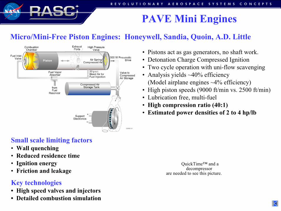
PAVE Mini EnginesMicro/Mini-Free Piston Engines: Honeywell, Sandia, Quoin, A.D. Little
• Pistons act as gas generators, no shaft work.• Detonation Charge Compressed Ignition• Two cycle operation with uni-flow scavenging• Analysis yields ~40% efficiency
(Model airplane engines ~4% efficiency)• High piston speeds (9000 ft/min vs. 2500 ft/min)• Lubrication free, multi-fuel • High compression ratio (40:1)• Estimated power densities of 2 to 4 hp/lb
Small scale limiting factors• Wall quenching• Reduced residence time• Ignition energy• Friction and leakage
Key technologies• High speed valves and injectors• Detailed combustion simulation
QuickTime™ and a decompressor
are needed to see this picture.
23
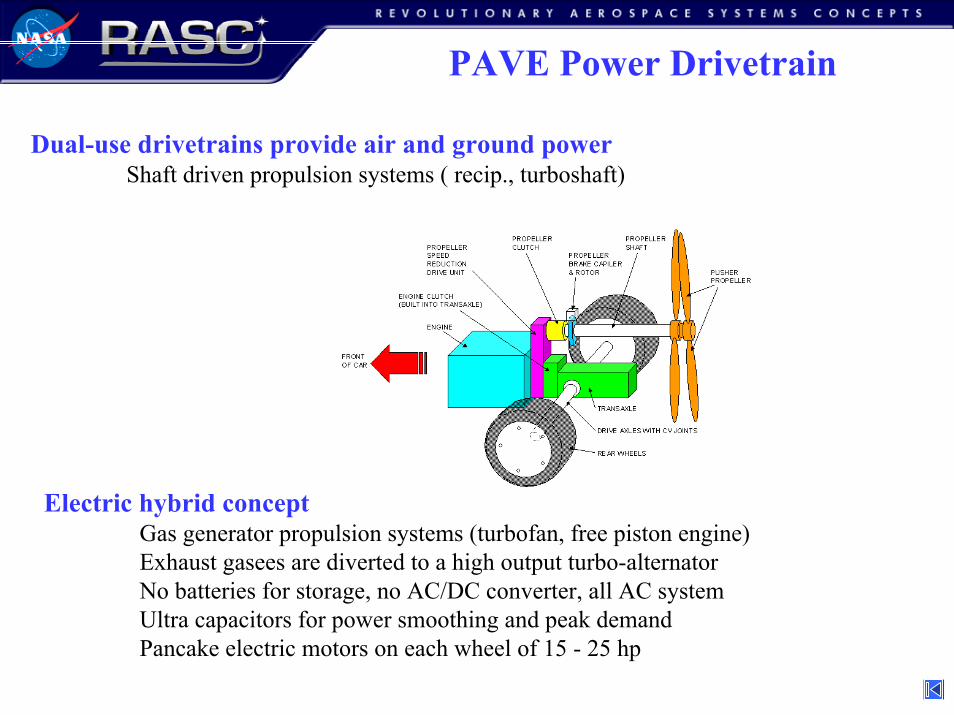
PAVE Power Drivetrain
Dual-use drivetrains provide air and ground powerShaft driven propulsion systems ( recip., turboshaft)
Electric hybrid conceptGas generator propulsion systems (turbofan, free piston engine)Exhaust gasees are diverted to a high output turbo-alternatorNo batteries for storage, no AC/DC converter, all AC systemUltra capacitors for power smoothing and peak demandPancake electric motors on each wheel of 15 - 25 hp
24
PAVE Electrical Propulsion
0
2
4
6
8
10
12
1960 1970 1980 1990 2000 2010 2020
Calendar Year
Powe
r D
ensi
ty fo
r Po
werp
lant
(kW
/kg)
Necar IIApolloGemini Shuttle
10-Fold Increase in Alkaline Power density
in 10 Years
7-Fold Increase in Automotive Power Density in 5
Years
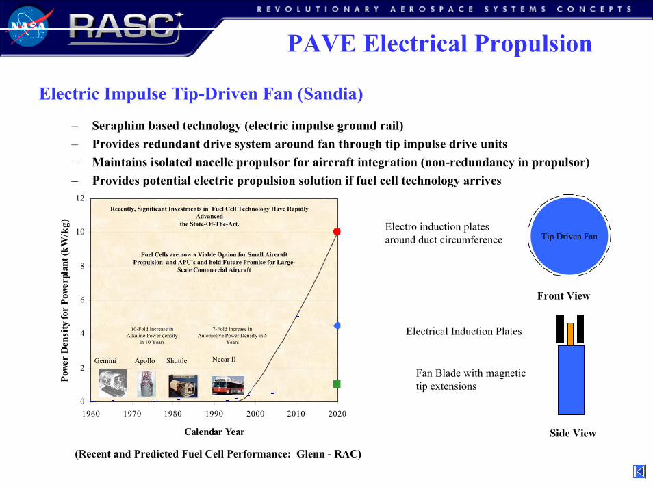
Recent and Anticipated Fuel CellPowerplant Improvements
Recently, Significant Investments in Fuel Cell Technology Have Rapidly Advanced
the State-Of-The-Art.
Fuel Cells are now a Viable Option for Small Aircraft Propulsion and APU’s and hold Future Promise for Large-
Scale Commercial Aircraft
(Recent and Predicted Fuel Cell Performance: Glenn - RAC)
Electric Impulse Tip-Driven Fan (Sandia)
– Seraphim based technology (electric impulse ground rail)– Provides redundant drive system around fan through tip impulse drive units– Maintains isolated nacelle propulsor for aircraft integration (non-redundancy in propulsor)– Provides potential electric propulsion solution if fuel cell technology arrives
Side View
Electrical Induction Plates
Fan Blade with magnetictip extensions
Tip Driven FanElectro induction platesaround duct circumference
Front View
25
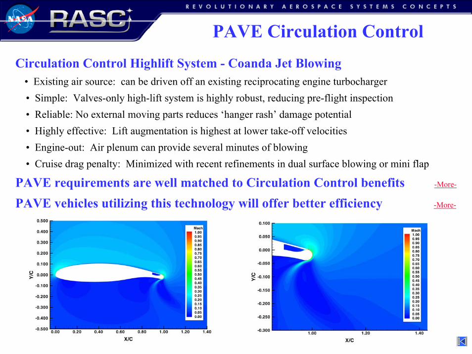
PAVE Circulation ControlCirculation Control Highlift System - Coanda Jet Blowing
• Existing air source: can be driven off an existing reciprocating engine turbocharger• Simple: Valves-only high-lift system is highly robust, reducing pre-flight inspection• Reliable: No external moving parts reduces ‘hanger rash’ damage potential• Highly effective: Lift augmentation is highest at lower take-off velocities• Engine-out: Air plenum can provide several minutes of blowing• Cruise drag penalty: Minimized with recent refinements in dual surface blowing or mini flap
PAVE requirements are well matched to Circulation Control benefits -More-
PAVE vehicles utilizing this technology will offer better efficiency -More-
26
PAVE Circulation Control
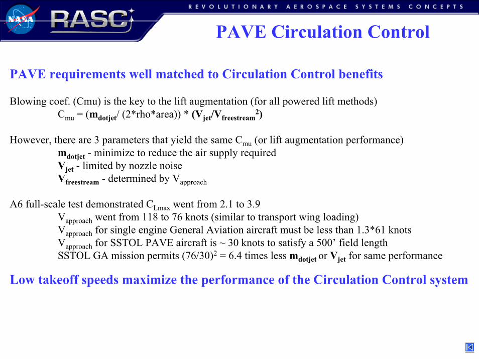
PAVE requirements well matched to Circulation Control benefits
Blowing coef. (Cmu) is the key to the lift augmentation (for all powered lift methods)Cmu = (mdotjet/ (2*rho*area)) * (Vjet/Vfreestream
2)
However, there are 3 parameters that yield the same Cmu (or lift augmentation performance)mdotjet - minimize to reduce the air supply required Vjet - limited by nozzle noiseVfreestream - determined by Vapproach
A6 full-scale test demonstrated CLmax went from 2.1 to 3.9Vapproach went from 118 to 76 knots (similar to transport wing loading)Vapproach for single engine General Aviation aircraft must be less than 1.3*61 knotsVapproach for SSTOL PAVE aircraft is ~ 30 knots to satisfy a 500’ field length SSTOL GA mission permits (76/30)2 = 6.4 times less mdotjet or Vjet for same performance
Low takeoff speeds maximize the performance of the Circulation Control system
27
PAVE Circulation Control
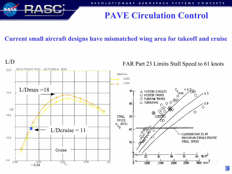
0.26
Cruise
~ 0.24
L/Dmax =18
L/Dcruise = 11
FAR Part 23 Limits Stall Speed to 61 knots
Current small aircraft designs have mismatched wing area for takeoff and cruise
L/D
28
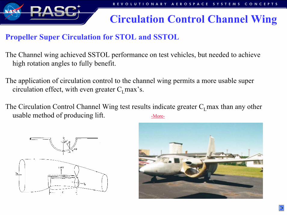
Circulation Control Channel WingPropeller Super Circulation for STOL and SSTOL
The Channel wing achieved SSTOL performance on test vehicles, but needed to achievehigh rotation angles to fully benefit.
The application of circulation control to the channel wing permits a more usable supercirculation effect, with even greater CLmax’s.
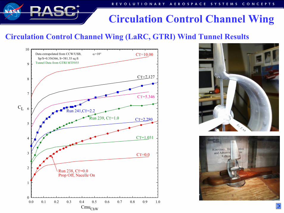
The Circulation Control Channel Wing test results indicate greater CLmax than any other usable method of producing lift. -More-
29
Circulation Control Channel WingCirculation Control Channel Wing (LaRC, GTRI) Wind Tunnel Results
0
1
2
3
4
5
6
7
8
9
10
CL
0.0 0.1 0.2 0.3 0.4 0.5 0.6 0.7 0.8 0.9 1.0CmuChW
Data extrapolated from CCW/USB, α=10° Sp/S=0.356366, S=381.35 sq ftTunnel Data from GTRI MTF055
CT=0.0
CT=1.031
CT=2.280
CT=5.346
CT=7.127
CT=10.00
Run 238, CT=0.0Prop Off, Nacelle On
Run 239, CT=1.0
Run 241,CT=2.2
30
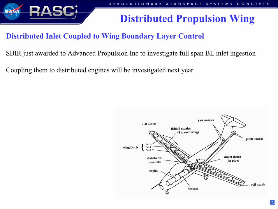
Distributed Propulsion WingDistributed Inlet Coupled to Wing Boundary Layer Control
SBIR just awarded to Advanced Propulsion Inc to investigate full span BL inlet ingestion
Coupling them to distributed engines will be investigated next year
31
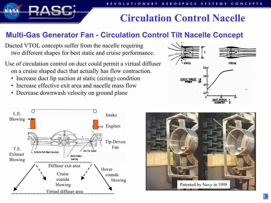
Circulation Control NacelleMulti-Gas Generator Fan - Circulation Control Tilt Nacelle ConceptDucted VTOL concepts suffer from the nacelle requiring
two different shapes for best static and cruise performance.
Use of circulation control on duct could permit a virtual diffuseron a cruise shaped duct that actually has flow contraction.• Increase duct lip suction at static (sizing) condition• Increase effective exit area and nacelle mass flow• Decrease downwash velocity on ground plane
Virtual diffuser area
Hover coanda
blowingCruise coanda blowing
Diffuser exit area
Tip-DrivenFan
L.E.Blowing
T.E.Exhaust Blowing
Engines
Intake
Patented by Navy in 1998

32
Circulation Control NacelleMulti-Gas Generator Fan - Circulation Control Tilt Nacelle Concept
Inlet Air
Induced Streamlines with LE blowing
LE Blowing
TE Exhaust BlowingInduced Streamlines without LE blowing
Objective: Smallest propulsion system power requirement possible for V/STOL, Yet have well matched disc-loading for hover and cruise, and a low cruise drag nacelle that can accommodate a high turn down ratio without spillage drag.

33
Circulation Control Nacelle
Multi-Gas Generator Fan - Circulation Control Tilt Nacelle Concept
Benefits ProblemsEliminates need for cross-shafting. (Engine-out)Provides bell mouth nacelle lip suction on cruise shaped nacelle (T/W requirement)Provides low cruise drag nacelle (Cruise drag)Reduces engine-out sizing penalty for VTOL hover (Engine sizing penalty)Provides downwash velocity reduction through increased diffusion. (Ground erosion/debris)Provides nacelle separation control in transition and crosswinds (Transition separation)
Plus, fuel is only being routed to nacelle, not all over…as in a ‘pure’ distributed concept.
While the gas generators are highly redundant, the fan isn’t redundant at all.
ASRS database analysis showed only 4% of all propulsion system reported problems wererelated to the fan, while 71% were due to the gas generators.
34
Span Constrained Structures
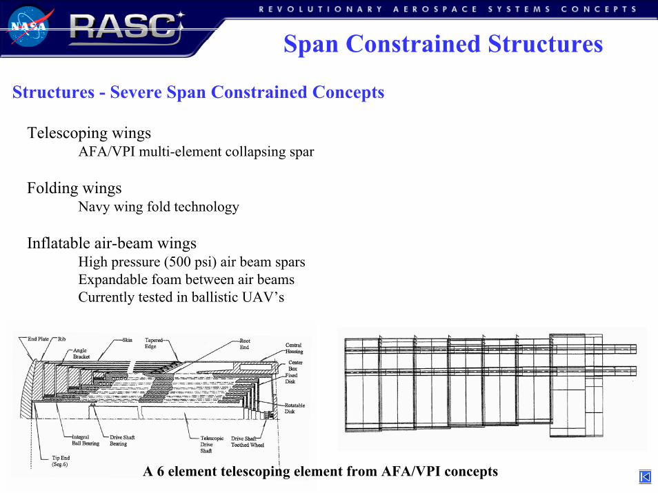
Structures - Severe Span Constrained Concepts
Telescoping wingsAFA/VPI multi-element collapsing spar
Folding wingsNavy wing fold technology
Inflatable air-beam wingsHigh pressure (500 psi) air beam sparsExpandable foam between air beamsCurrently tested in ballistic UAV’s
A 6 element telescoping element from AFA/VPI concepts
35
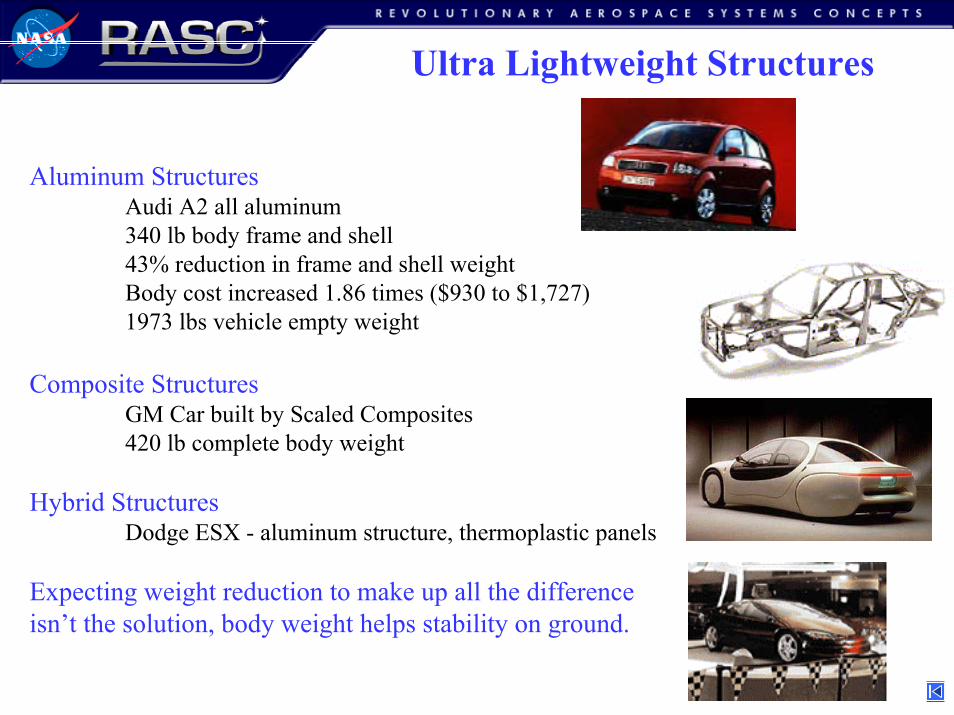
Ultra Lightweight Structures
Aluminum StructuresAudi A2 all aluminum340 lb body frame and shell43% reduction in frame and shell weight Body cost increased 1.86 times ($930 to $1,727)1973 lbs vehicle empty weight
Composite StructuresGM Car built by Scaled Composites 420 lb complete body weight
Hybrid StructuresDodge ESX - aluminum structure, thermoplastic panels
Expecting weight reduction to make up all the differenceisn’t the solution, body weight helps stability on ground.
36
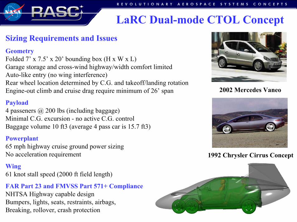
LaRC Dual-mode CTOL ConceptSizing Requirements and IssuesGeometryFolded 7’ x 7.5’ x 20’ bounding box (H x W x L)Garage storage and cross-wind highway/width comfort limitedAuto-like entry (no wing interference)Rear wheel location determined by C.G. and takeoff/landing rotationEngine-out climb and cruise drag require minimum of 26’ span
Payload4 passeners @ 200 lbs (including baggage)Minimal C.G. excursion - no active C.G. controlBaggage volume 10 ft3 (average 4 pass car is 15.7 ft3)
Powerplant65 mph highway cruise ground power sizingNo acceleration requirement
Wing61 knot stall speed (2000 ft field length)
FAR Part 23 and FMVSS Part 571+ ComplianceNHTSA Highway capable designBumpers, lights, seats, restraints, airbags, Breaking, rollover, crash protection
2002 Mercedes Vaneo
1992 Chrysler Cirrus Concept
37
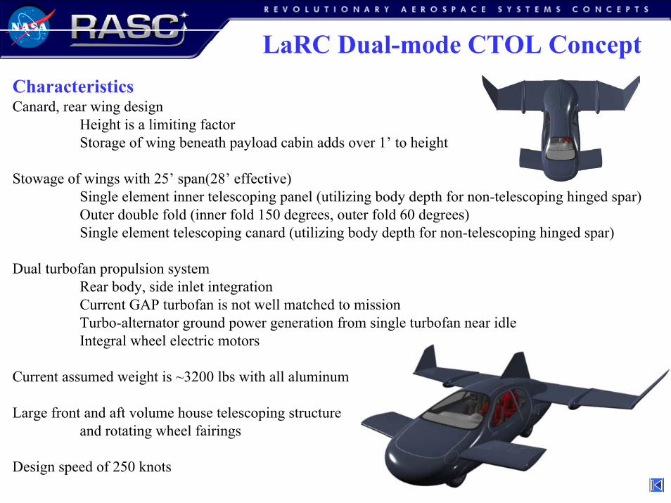
LaRC Dual-mode CTOL ConceptCharacteristicsCanard, rear wing design
Height is a limiting factorStorage of wing beneath payload cabin adds over 1’ to height
Stowage of wings with 25’ span(28’ effective)Single element inner telescoping panel (utilizing body depth for non-telescoping hinged spar)Outer double fold (inner fold 150 degrees, outer fold 60 degrees)Single element telescoping canard (utilizing body depth for non-telescoping hinged spar)
Dual turbofan propulsion systemRear body, side inlet integrationCurrent GAP turbofan is not well matched to missionTurbo-alternator ground power generation from single turbofan near idleIntegral wheel electric motors
Current assumed weight is ~3200 lbs with all aluminum
Large front and aft volume house telescoping structureand rotating wheel fairings
Design speed of 250 knots
38
VPI Dual-mode CTOL Concept
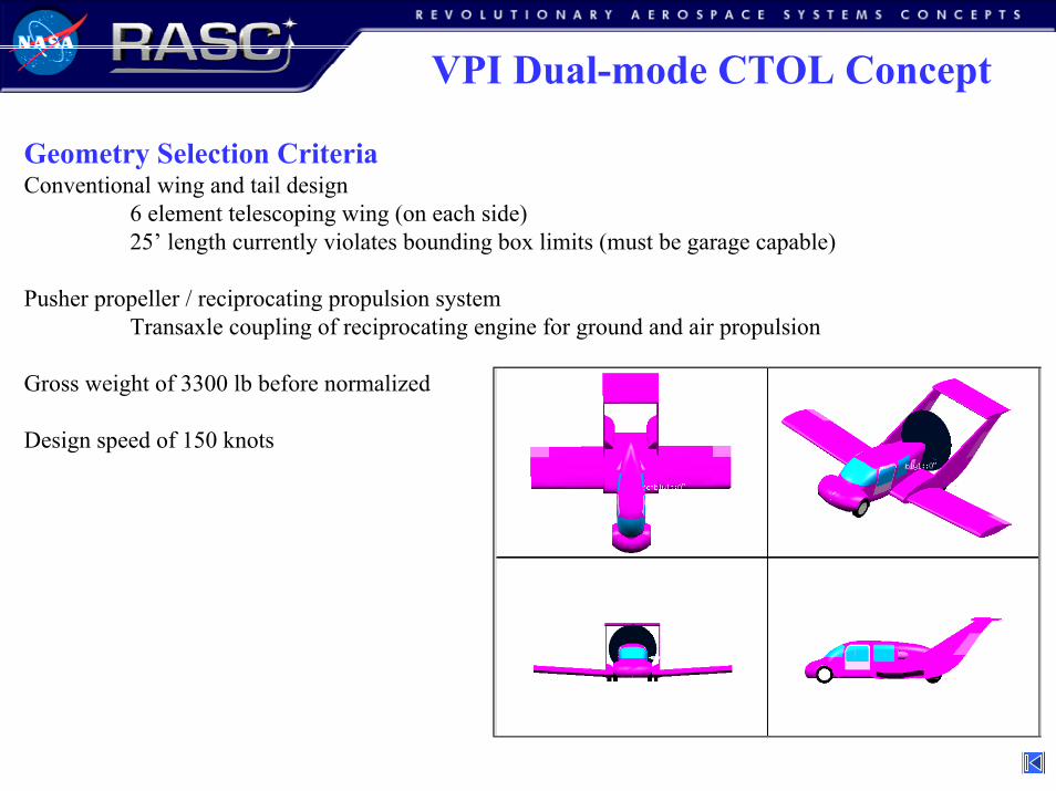
Geometry Selection CriteriaConventional wing and tail design
6 element telescoping wing (on each side)25’ length currently violates bounding box limits (must be garage capable)
Pusher propeller / reciprocating propulsion systemTransaxle coupling of reciprocating engine for ground and air propulsion
Gross weight of 3300 lb before normalized
Design speed of 150 knots

39
LaRC Single-mode VTOL Concept
Multi-Gas Generator Fan - Circulation Control Tilt Nacelle Concept
2 person payload 10’ W x 7’ H x 20’ L folded - Foldable outer wing panels
Minimize powered lift complexity and uncertaintyBased on Grumman 698 design with established databaseAll control forces generated through engine control vanesEngine rotation brake system - No mechanical rotation, uses thrust deflection vanesNo Reaction Control System required
Slight forward sweep outer panels for center of lift co-location with C.G. in hover
Multiple small gas generators powered tip turbine fansMinimizes engine-out sizing condition
Circulation control nacelle virtual diffuserStatic and cruise optimized duct shapeLimits nacelle diameter
Approximately 2000 lbs gross weight
40
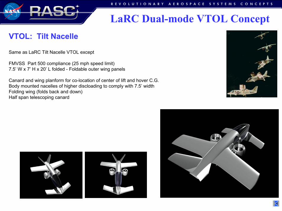
VTOL: Tilt Nacelle
Same as LaRC Tilt Nacelle VTOL except
FMVSS Part 500 compliance (25 mph speed limit)7.5’ W x 7’ H x 20’ L folded - Foldable outer wing panels
Canard and wing planform for co-location of center of lift and hover C.G.Body mounted nacelles of higher discloading to comply with 7.5’ widthFolding wing (folds back and down)Half span telescoping canard
LaRC Dual-mode VTOL Concept
41
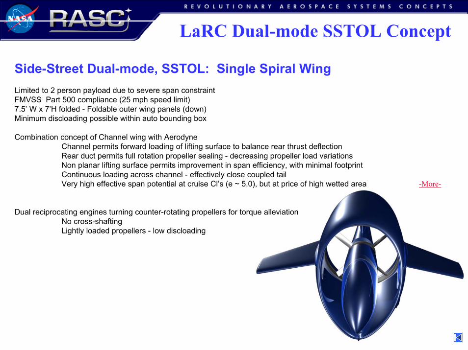
LaRC Dual-mode SSTOL Concept
Side-Street Dual-mode, SSTOL: Single Spiral WingLimited to 2 person payload due to severe span constraintFMVSS Part 500 compliance (25 mph speed limit)7.5’ W x 7’H folded - Foldable outer wing panels (down)Minimum discloading possible within auto bounding box
Combination concept of Channel wing with AerodyneChannel permits forward loading of lifting surface to balance rear thrust deflectionRear duct permits full rotation propeller sealing - decreasing propeller load variationsNon planar lifting surface permits improvement in span efficiency, with minimal footprintContinuous loading across channel - effectively close coupled tailVery high effective span potential at cruise Cl’s (e ~ 5.0), but at price of high wetted area -More-
Dual reciprocating engines turning counter-rotating propellers for torque alleviationNo cross-shaftingLightly loaded propellers - low discloading

42
Single-mode Concepts
Single Mode CTOL, STOL, SSTOL: Tailfan
Model T of the airRental car to complete doorstep operation
Low cost design approach - meet a minimum buy/operate cost to offset no ground capabilityAutomotive derivative engine with turbocharger (for altitude compensation only)Direct drive tailfan @ 3500 rpm (lower engine specific output, no gear reduction)Design for manufacturing approach instead of design for performanceMinimize number of panel molds - symmetric tail, duct, and some wing sectionsAero performance penalty for simplified skin stiffened structure
Low noise design approach - meet the noise constraint with minimum penaltyHamilton Standard Qfan derivative fan Low tip speed on fan (decreased performance)Low discloadingMulti-bladed higher frequency noiseAcoustic duct shieldingUniform inflowLarge muffler volume in tailcone
STOL version: Full span flaps and leading edge slotSSTOL version: Turbocharger powered circulation control highlift system for
43
Study Results
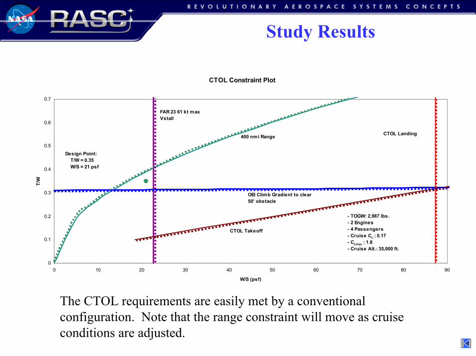
CTOL Constraint Plot
0
0.1
0.2
0.3
0.4
0.5
0.6
0.7
0 10 20 30 40 50 60 70 80 90
W/S (psf)
T/W
- TOGW: 2,987 lbs. - 2 Engines - 4 Passengers - Cruise CL : 0.17 - CLmax : 1.8 - Cruise Alt.: 35,000 ft.
400 nmi Range
OEI Climb Gradient to clear50' obstacle
FAR 23 61 kt max Vstall
CTOL Takeoff
CTOL Landing
Design Point: T/W = 0.35 W/S = 21 psf
The CTOL requirements are easily met by a conventional configuration. Note that the range constraint will move as cruise conditions are adjusted.
44
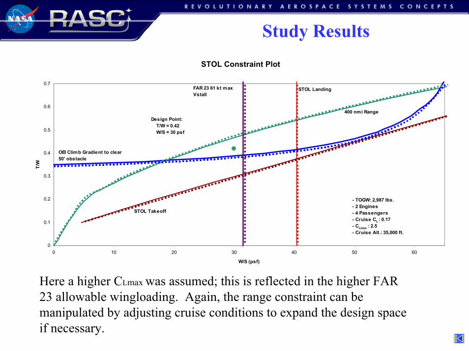
STOL Constraint Plot
0
0.1
0.2
0.3
0.4
0.5
0.6
0.7
0 10 20 30 40 50 60
W/S (psf)
T/W
- TOGW: 2,987 lbs. - 2 Engines - 4 Passengers - Cruise CL : 0.17 - CLmax : 2.5 - Cruise Alt.: 35,000 ft.
400 nmi Range
OEI Climb Gradient to clear50' obstacle
Design Point: T/W = 0.42 W/S = 30 psf
FAR 23 61 kt max Vstall
STOL Landing
STOL Takeoff
Here a higher CLmax was assumed; this is reflected in the higher FAR 23 allowable wingloading. Again, the range constraint can be manipulated by adjusting cruise conditions to expand the design space if necessary.
Study Results
45
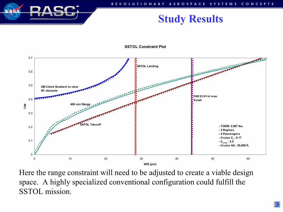
Study Results
Here the range constraint will need to be adjusted to create a viable design space. A highly specialized conventional configuration could fulfill the SSTOL mission.
SSTOL Constraint Plot
0
0.1
0.2
0.3
0.4
0.5
0.6
0.7
0 10 20 30 40 50 60
W/S (psf)
T/W
- TOGW: 2,987 lbs. - 2 Engines - 4 Passengers - Cruise CL : 0.17 - CLmax : 3.5 - Cruise Alt.: 35,000 ft.
400 nmi Range
FAR 23 61 kt max Vstall
OEI Climb Gradient to clear50' obstacle
SSTOL Landing
SSTOL Takeoff

46
Study Results
VTOL Constraint Plot
0
0.1
0.2
0.3
0.4
0.5
0.6
0.7
0 10 20 30 40 50 60
W/S (psf)
T/W
- TOGW: 2,987 lbs. - 2 Engines - 4 Passengers - Cruise CL : 0.17 - CLmax : 6.5 - Cruise Alt.: 35,000 ft.
400 nmi Range
VTOL Landing
OEI Climb Gradient to clear50' obstacle
VTOL Takeoff
It is doubtful that a conventional configuration will meet the VTOL requirements even with the assumed CLmax of 6.5.
47
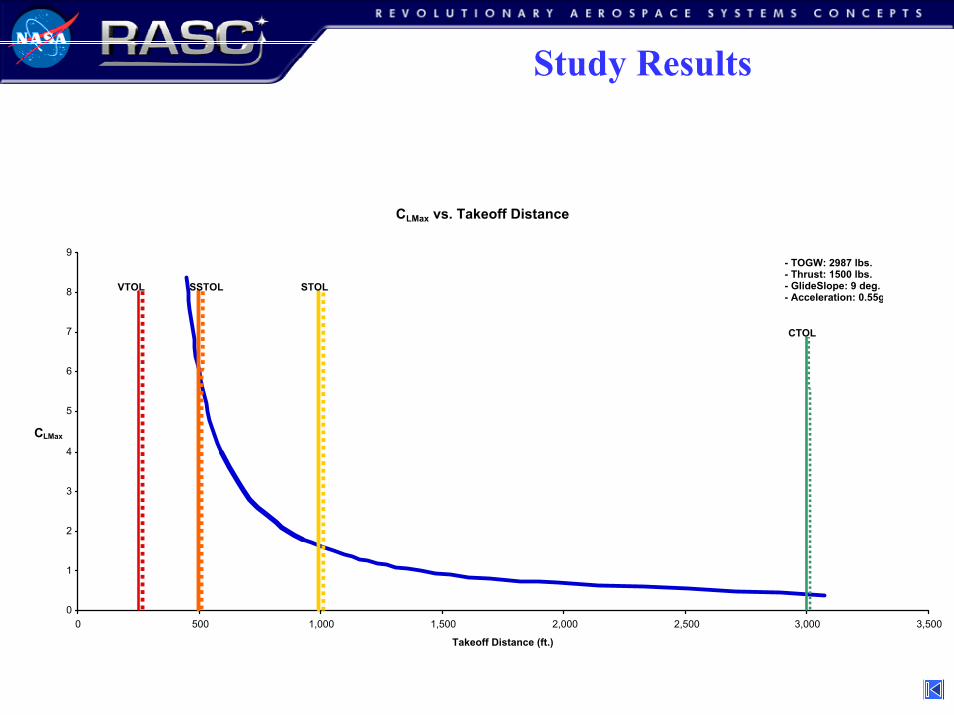
Study Results
CLMax vs. Takeoff Distance
0
1
2
3
4
5
6
7
8
9
0 500 1,000 1,500 2,000 2,500 3,000 3,500
Takeoff Distance (ft.)
CLMax
- TOGW: 2987 lbs. - Thrust: 1500 lbs. - GlideSlope: 9 deg. - Acceleration: 0.55g
STOL
CTOL
SSTOLVTOL
48
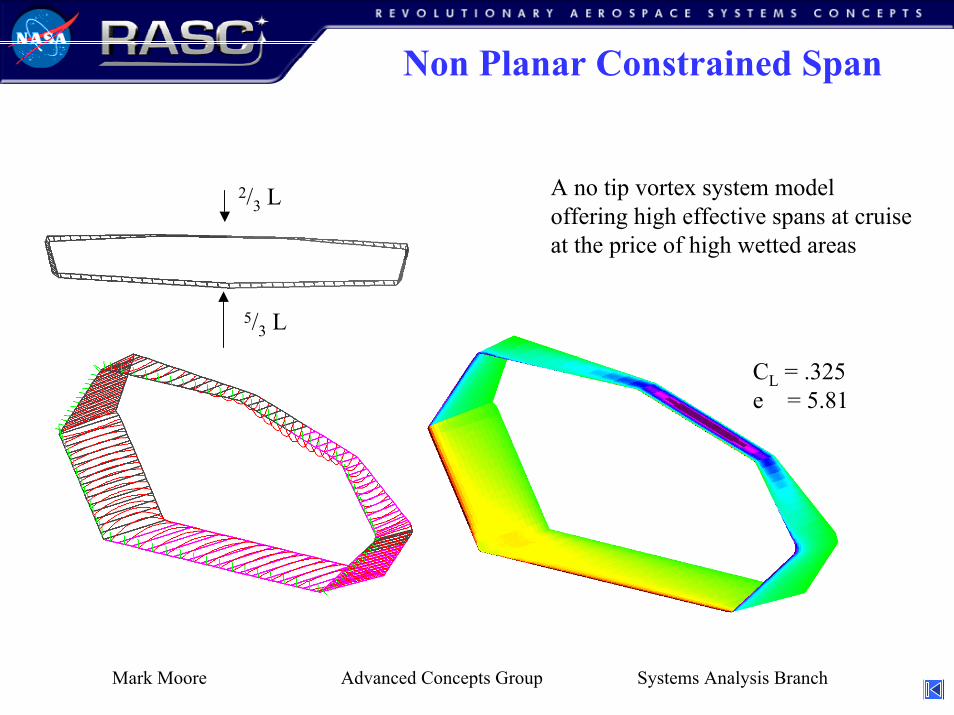
Non Planar Constrained Span
CL = .325e = 5.81
2/3 L
5/3 L
A no tip vortex system modeloffering high effective spans at cruiseat the price of high wetted areas
Mark Moore Advanced Concepts Group Systems Analysis Branch


![Passenger Vehicle Technology: U.S. CAFE and GHG …ccap.org/assets/German-US-CAFE-and-GHG-standards.pdf · [1] China's t arget refl ect s gasoline fl eet scenario. If including ot](https://img.pdfslide.net/doc/110x75/5b4f59b57f8b9a2a6e8c1fcb/passenger-vehicle-technology-us-cafe-and-ghg-ccaporgassetsgerman-us-cafe-and-ghg-.jpg)