Embed Size (px)
Citation preview
OWNER’S / OPERATOR’S MANUAL
Read this manual carefully before operating this vehicle.
J0E-F8199-11LIT-19626-A0-08
DR2E PTV
PERSONAL TRANSPORT VEHICLE
2019MODEL YEAR
©2019 Yamaha Golf-Car Com
pany

©2019 Yamaha Golf-Car Com
pany
INTRODUCTIONCongratulations on your purchase of aYamaha Personal Transport Vehicle(PTV). This manual contains informationyou will need for proper operation, maintenance, and care of your PTV. A thorough understanding of these simpleinstructions will help you to obtain maximum enjoyment from your newYamaha.
If you have any questions about theoperation or maintenance of your PTV,please consult a Yamaha dealer.
Yamaha Golf-Car Company
DR2E PTVOwner's/Operator's Manual
© 2019 by Yamaha Golf-Car Company1st edition
All rights reserved. Any reprintingor unauthorized use without the
written permission ofYamaha Golf-Car Company
is expressly prohibited.Printed in U.S.A.LIT-19626-A0-08
iJ0E
©2019 Yamaha Golf-Car Com
pany
ii J0E
IMPORTANT MANUAL INFORMATION
TIPYamaha continually seeks advancements in product designand quality; therefore, while thismanual contains the most currentproduct information available at thetime of printing, there may be minordiscrepancies between your PTVand this manual. If you have anyquestions concerning this manual,please consult your Yamaha dealer.
Read and understand this manualcompletely before operating yourPTV. This manual should beconsidered a permanent part ofyour PTV and should remain withthe PTV when resold.
Particularly important information isdistinguished in this manual by the following notations:
This is the safety alert symbol. It isused to alert you to potentialpersonal injury hazards. Obey allsafety messages that follow thissymbol to avoid possible injury ordeath.
A WARNING indicates a hazardoussituation which, if not avoided,could result in death or seriousinjury.
A NOTICE indicates specialprecautions that must be taken toavoid damage to the PTV or otherproperty.
TIPA TIP provides key information tomake procedures easier or clearer.
NOTICE
©2019 Yamaha Golf-Car Com
pany
iiiJ0E
1
WARRANTY
CONTENTS
1
IMPORTANT LABELS 2
SAFETY CONSIDERATIONS 4
MAINTENANCE 8
STORAGE
SPECIFICATIONS
9
WIRING 11
OPERATION 7
PRE-OPERATION CHECKS 6
CONTROLS 5
OPERATOR SAFETY 3
10
©2019 Yamaha Golf-Car Com
pany
1
2
3
4
5
6
7
8
9
10
11
1-1 J0E
WARRANTY
straPnommoCFrame
elxasnarTsladeP
)sdap/seohsgnidulcxe(sekarBsyalerdna,sehctiws,seriwlacirtcelE
stnenopmocgnireetS/noisnepsuSstaeS
poTnuSstraPydoB/srepmuB
staMroolFsredloHdracerocS
reirraCgaBCommon Accessories
dleihsdniWthgiL daeH
thgiL liaT
4 Years3 Years
3 Years4 Years3 Years4 Years2 Years4 Years3 Years2 Years2 Years3 Years
3 Years2 Years2 Years
4 Years4 Years
4 Years4 Years2 Years
4 Years4 Years2 Years1 Year4 Years
1 Year
cificepS raC cirtcelE4 Years or 23,500 amp-hours
whichever comes first*Detailed condition on the next page
Battery - Trojan ' T875 ' withoutHydroLink Watering System
rotoMcirtcelE
regrahC 4 YearsrellortnoCrotoM
droCregrahCelcatpeceRregrahC
rosneSnoitisoPelttorhTGAS Car specific
rotareneG/ekatnI/tsuahxEenignEsaG
slortnoC/selbaCelttorhTyrettaB
)tlebevirdgnidulcxe(hctulC
straPgniniameRllA
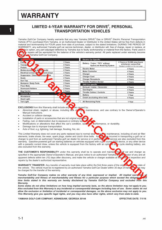
Yamaha Golf-Car Company hereby warrants that any new Yamaha DRIVE2 Gas or DRIVE2 Electric Personal Transportation Vehicle (PTV) purchased from Yamaha, or an Authorized Dealer or Distributor in the United States will be free from defects in material and workmanship for FOUR years from date of purchase, subject to the stated limitations. DURING THE PERIOD OF WARRANTY, any authorized Yamaha golf car service technician, dealer, or distributor will, free of charge, repair or replace, atYamaha’s option, any part adjudged defective by Yamaha due to faulty workmanship or material from the factory. Parts used in warranty repairs will be warranted for the balance of the vehicle’s warranty period. All parts replaced under warranty become property of Yamaha Golf-Car Company.
EXCLUSIONS from this Warranty shall include any failures caused by: Abnormal strain, neglect, or abuse, including lack of proper maintenance, and use contrary to the Owner’s/Operator’s
Manual instructions. Accident or collision damage. Installation of parts or accessories that are not original equipment. Fading, rust, or deterioration due to exposure or ordinary wear and tear. Modifications or alterations that affect the car’s condition, operation, performance, or durability. Damage due to improper transportation. Acts of God, e.g. lightning, hail damage, flooding, fire, etc.
This Limited Warranty does not cover any parts replaced due to normal wear or routine maintenance, including oil and air filterelements, brake shoes, tire wear, spark plugs, starter and clutch drive belts. Any charges incurred in transporting a golf car or charger to and from an authorized Yamaha golf car dealer for service or in performing field service are also excluded from thiswarranty. Gasoline-powered golf car starting batteries on vehicles equipped with a golf course GPS device, or any other devicewith a parasitic current draw, unless the vehicle is equipped from the factory with an optional deep cycle starting battery, are also excluded from this warranty.
THE CUSTOMER’S RESPONSIBILITY under this warranty shall be to operate and maintain the golf car and charger as specified in the appropriate Owner’s/Operator’s Manual, and give notice to an authorized Yamaha golf car dealer of any and all apparent defects within ten (10) days after discovery, and make the vehicle or charger available at that time for inspection and repairs by the dealer’s authorized representative.
WARRANTY TRANSFER: Any transfer of warranty must take place within the first three years of the original in-service date of the vehicle. The vehicle must be re-registered by an authorized Yamaha Golf-Car Dealer within 30 days of transfer. A fee may be charged for the transfer of the warranty.
YAMAHA GOLF-CAR COMPANY, KENNESAW, GEORGIA 30144 EFFECTIVE DATE: 7/1/16
LIMITED 4-YEAR WARRANTY FOR DRIVE2, PERSONALTRANSPORTATION VEHICLES
Yamaha Golf-Car Company makes no other warranty of any kind, expressed or implied. All implied warranties of merchantability and fitness of merchantability and fitness for a particular purpose which exceed the obligations and time limits stated in this warranty are hereby disclaimed by Yamaha Golf-Car Company and excluded from this Warranty.Some states do not allow limitations on how long implied warranty lasts, so the above limitation may not apply to you. Also excluded from this Warranty is any incidental or consequential damages including loss of use. Some states do not allow the exclusion or limitation of incidental or consequential damages, so the above exclusion may not apply to you.This Warranty give you specific legal rights, and you may also have other rights, which vary from state to state.
©2019 Yamaha Golf-Car Com
pany
1
2
3
4
5
6
7
8
9
10
11
WARRANTY
1-2J0E
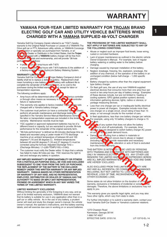
Yamaha Golf-Car Company (herein referred to as “YGC”) herebywarrants to the Original Retail Purchaser or Lessee of a YAMAHA TheDrive golf car or PTV, Adventurer utility vehicle, or YAMAHA Conciergetransportation or specialty car purchased from Yamaha, or anAuthorized Dealer or Distributor in the United States, that the Trojanbatteries charged with a YAMAHA battery charger will be free fromdefects in materials and workmanship, and will provide “36-holeperformance” as follows:
4-years or 23,500 amp-hours with T-8754-years or 25,000 amp-hours with T-875 batteries & the addition ofa factory-installed Trojan HydroLink Battery Watering System.
WARRANTY LIMITATIONSYamaha Golf-Car Company’s and Trojan Battery Company’s limit ofliability shall be to replace a defective battery. Replacement shallmean furnishing a new battery or used battery with sufficient life tocomplete the remainder of the warranty term, at no cost to thepurchaser during the limited warranty period, except for labor ortransportation expenses.
The following conditions apply:
Amp-hours will be determined either through the Genius controlleror through other means as necessary in the event of a controllerfailure or replacement.This warranty only applies to factory installed Trojan battery setscharged with a Yamaha battery charger.The customer must perform (or have a contracted Yamaha Dealerperform) all periodic maintenance and discharge testing asspecified in the Yamaha Service Manual Maintenance Schedule.No labor or transportation expenses are included in this limitedwarranty. Maintenance records must be kept.YGC supplied or approved replacement batteries may be of adifferent brand or capacity, but are warranted to provide 36-holeperformance for the remainder of the original warranty term.“36-hole performance” is defined as 60-minutes discharge time astested and recorded using a Lester model #17770 dischargemachine at an ambient temperature of between 60 and 100degrees F (16 and 38 degrees C). Ambient temperaturesbetween 60 and 80 degrees F (16 and 27 degrees C) must becorrected using the formula: Adjusted Discharge Time =(Discharge Minutes) / (1-(((80-TEMP)/100) x 0.64)).The customer must notify the Dealer within 10 days that a vehiclehas failed to make 36 holes per day. YGC reserves the right totest and recharge any battery in question.
ANY IMPLIED WARRANTY OF MERCHANTABILITY OR FITNESSFOR A PARTICULAR PURPOSE SHALL BE VOID AND EXCLUDEDSUBSEQUENT TO ONE YEAR FROM THE DATE OF PURCHASE.THE REPLACEMENT OF THE BATTERY IS THE EXCLUSIVEREMEDY UNDER THIS WRITTEN WARRANTY OR ANY IMPLIEDWARRANTY. YAMAHA MAKES NO OTHER REPRESENTATIONOR WARRANTY OF ANY KIND, AND NO REPRESENTATIVE,EMPLOYEE, DISTRIBUTOR OR DEALER OF YAMAHA HAS THEAUTHORITY TO MAKE OR IMPLY ANY REPRESENTATION,PROMISE OR AGREEMENT WHICH IN ANY WAY VARIES THETERMS OF THIS LIMITED WARRANTY.
LIMITED WARRANTY EXCLUSIONSWithout limiting the generality of the foregoing in any way, and aspart of its limited warranty exclusion, YAMAHA does not warrantthat its battery is suitable for use in any application other than in agolf car or utility vehicle. As in the use of any battery, a prudentowner will read and study the charger owner’s manual, the vehicleowner’s manual, the operator’s instructions, and the battery warninglabels; and will exercise due care in working on or around batteries.
THE PROVISIONS OF THIS LIMITED WARRANTY SHALLNOT APPLY IF BATTERIES ARE SUBJECTED TO ANY OFTHE FOLLOWING CONDITIONS:
Abuse or neglect such as improper fluid levels, loose wiring,rusted or corroded hardware.Lack of proper maintenance as outlined in the electric vehicleOwner’s/Operator’s Manual. For example, lack of regularbattery watering or adding water to the battery beforecharging.Damage caused by improper installation of the battery.Neglect, breakage, freezing, fire, explosion, wreckage, theaddition of any chemical, or the operation of the battery in anuncharged condition (below half-charge – 1.200 specificgravity).Battery charged by systems other than the original equipmenttype battery charger.On fleet golf cars, the use of any non-YAMAHA suppliedelectrical devices that consume more than one amp-hour perround or two amp-hours per day of battery energy. Examplesof these devices include, but are not limited to: heating orcooling systems; GPS (global position system) devices;information gathering devices; lights; radios or stereos; oryardage measuring devices.Less than one charger per car or inadequate facility electricalpower to power all chargers. Examples include more thanone charger on a single circuit, circuit rating of less than 15amps, or not enough circuits for the number of cars.In fleet applications, less than one battery charger per vehicle.For example, using only 10 battery chargers to charge a 15car fleet. The use of any system that does not allow the batterychargers to shut off automatically. For example, timersystems that are designed to switch battery charger AC poweron and off during peak demand hours.Damage not resulting from a defect in materials orworkmanship or which occurs due to abuse or neglect(including failure to provide reasonable and necessarymaintenance), accident, alteration or acts of God is excludedfrom this limited warranty.
THIS BATTERY IS INTENDED TO BE USED BY PERSONSWITH TRAINING AND EXPERIENCE WITH BATTERIES ANDONLY IN YAMAHA ELECTRIC VEHICLES. ANY OTHER USERENDERS THE LIMITED WARRANTIES EXPRESSED HEREINAND ALL IMPLIED WARRANTIES NULL AND VOID AND SAMEARE HEREBY EXCLUDED.
ALSO EXCLUDED FROM THIS LIMITED WARRANTY AREANY AND ALL INCIDENTAL OR CONSEQUENTIAL DAMAGESINCLUDING, BUT NOT LIMITED TO, LOSS OF USE ORREVENUE, LOSS OF TIME, INCONVENIENCE OR ANYOTHER ECONOMIC LOSS.
Some states do not allow limitation on the duration of an impliedwarranty, exclusions or limitations of incidental or consequentialdamages. Therefore, the above limitations or exclusions may notapply to you.
This warranty gives you specific legal rights, and you may alsohave other rights, which vary from state to state.
For further information or to submit a warranty claim, contact yourlocal Yamaha Golf-Car Dealer or Yamaha’s customer relations.
EFFECTIVE DATE: 07/01/16 LIT-13710-EL-14
YAMAHA FOUR-YEAR LIMITED WARRANTY FOR TROJAN BRANDELECTRIC GOLF CAR AND UTILITY VEHICLE BATTERIES WHEN
CHARGED WITH A YAMAHA SUPPLIED 48-VOLT CHARGER
1270 Chastain Road Kennesaw, Georgia 301441-866-747-4027
©2019 Yamaha Golf-Car Com
pany
1
2
3
4
5
6
7
8
9
10
11
2-1 J0E
4 65
Y-2828
12
3
SAFETY AND INSTRUCTION LABELS
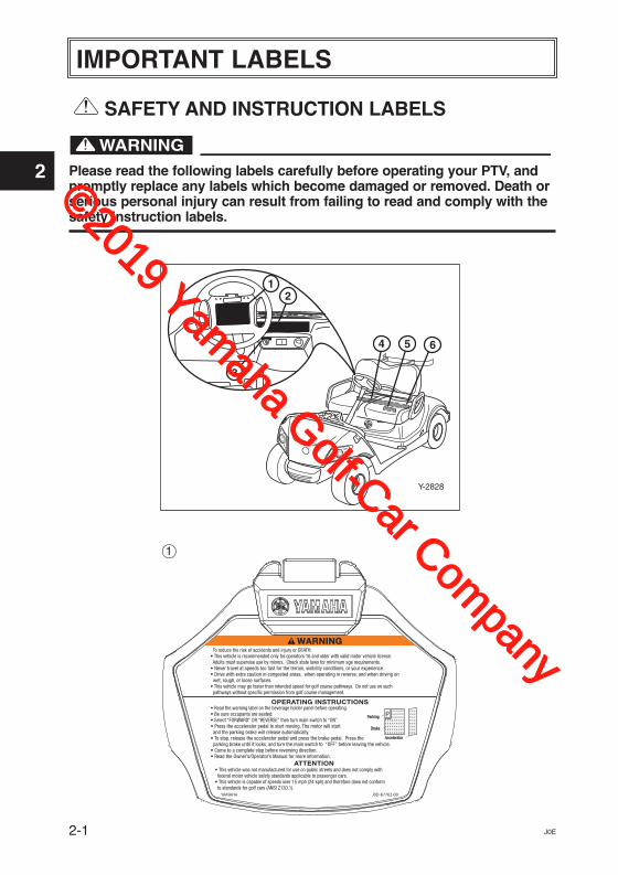
Please read the following labels carefully before operating your PTV, andpromptly replace any labels which become damaged or removed. Death orserious personal injury can result from failing to read and comply with thesafety instruction labels.
IMPORTANT LABELS
1
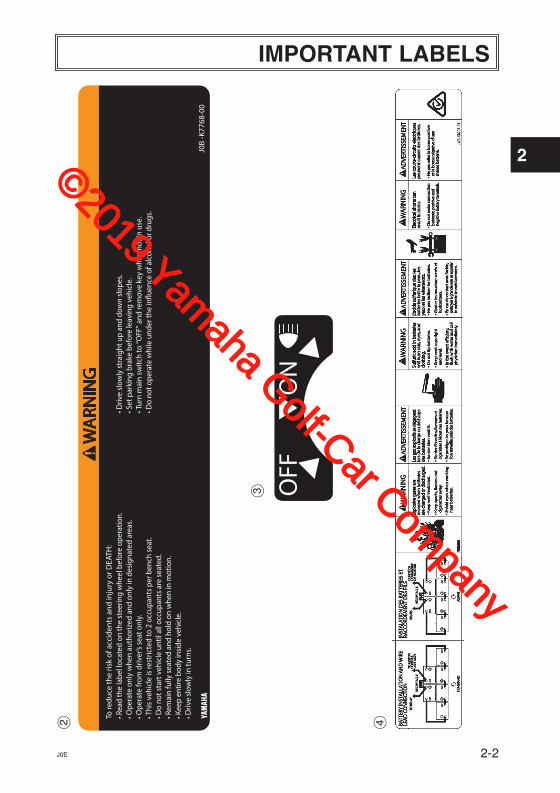
WARNINGWARNING To reduce the risk of accidents and injury or DEATH:• This vehicle is recommended only for operators 16 and older with valid motor vehicle license. Adults must supervise use by minors. Check state laws for minimum age requirements.• Never travel at speeds too fast for the terrain, visibility conditions, or your experience.• Drive with extra caution in congested areas, when operating in reverse, and when driving on wet, rough, or loose surfaces.• This vehicle may go faster than intended speed for golf course pathways. Do not use on such pathways without specific permission from golf course management.
• Read the warning label on the beverage holder panel before operating.• Be sure occupants are seated.• Select “FORWARD” OR “REVERSE” then turn main switch to “ON”.• Press the accelerator pedal to start moving. The motor will start and the parking brake will release automatically.• To stop, release the accelerator pedal and press the brake pedal. Press the parking brake until it locks, and turn the main switch to “OFF” before leaving the vehicle.• Come to a complete stop before reversing direction.• Read the Owner’s/Operator’s Manual for more information.
• This vehicle was not manufactured for use on public streets and does not comply with federal motor vehicle safety standards applicable to passenger cars.• This vehicle is capable of speeds over 15 mph (24 kph) and therefore does not conform to standards for golf cars (ANSI Z130.1).
OPERATING INSTRUCTIONS
ATTENTION
YAMAHA J0D-K7762-00
PParkingParking
BrakeBrake
AcceleratorAccelerator
©2019 Yamaha Golf-Car Com
pany
1
2
3
4
5
6
7
8
9
10
11
IMPORTANT LABELS
2-2J0E
42
3
©2019 Yamaha Golf-Car Com
pany
IMPORTANT LABELS
1
2
3
4
5
6
7
8
9
10
11
2-3 J0E
5
6
NOTICE
NOTIFICATION
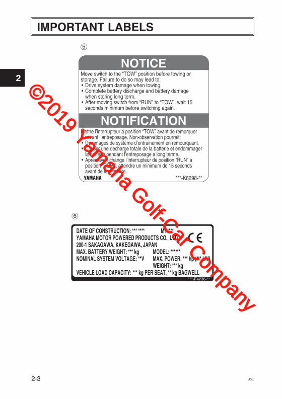
Move switch to the “TOW” position before towing orstorage. Failure to do so may lead to:• Drive system damage when towing.• Complete battery discharge and battery damage
when storing long term.• After moving switch from “RUN” to “TOW”, wait 15
seconds minimum before switching again.
Mettre l’interrupteur a position “TOW” avant de remorquerou avant l’entreposage. Non-observation pourrait:• Dommages de système d’entrainement en remourquant.• Causer une decharge totale de la batterie et endommager
la batterie pendant l’entreposage a long terme.• Apres avoir change l’interrupteur de position “RUN” a
position “TOW”, attendre un minimum de 15 secondsavant de le remettre.
***-K8298-**
DATE OF CONSTRUCTION: *** **** MY****YAMAHA MOTOR POWERED PRODUCTS CO., LTD200-1 SAKAGAWA, KAKEGAWA, JAPANMAX. BATTERY WEIGHT: *** kgNOMINAL SYSTEM VOLTAGE: **V
VEHICLE LOAD CAPACITY: *** kg PER SEAT, ** kg BAGWELL
MODEL: ******MAX. POWER: *** hp (*** kW)WEIGHT: *** kg
***-F4236-**
©2019 Yamaha Golf-Car Com
pany
1
2
3
4
5
6
7
8
9
10
11
2-4J0E
Y-2829
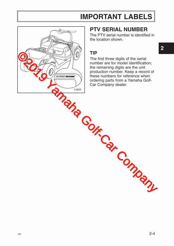
PTV SERIAL NUMBERThe PTV serial number is identified inthe location shown.
TIPThe first three digits of the serialnumber are for model identification;the remaining digits are the unitproduction number. Keep a record ofthese numbers for reference whenordering parts from a Yamaha Golf-Car Company dealer.
IMPORTANT LABELS
©2019 Yamaha Golf-Car Com
pany
OPERATOR SAFETY
1
2
3
4
5
6
7
8
9
10
11
3-1
!
Y-2830
Y-68
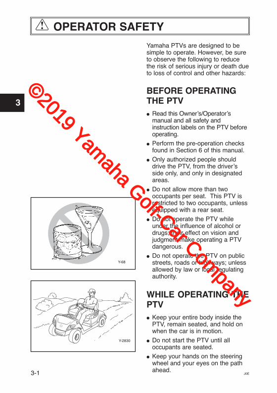
Yamaha PTVs are designed to besimple to operate. However, be sureto observe the following to reducethe risk of serious injury or death dueto loss of control and other hazards:
BEFORE OPERATINGTHE PTV� Read this Owner’s/Operator’s
manual and all safety andinstruction labels on the PTV beforeoperating.
� Perform the pre-operation checksfound in Section 6 of this manual.
� Only authorized people shoulddrive the PTV, from the driver’sside only, and only in designatedareas.
� Do not allow more than twooccupants per seat. This PTV isrestricted to two occupants, unlessequipped with a rear seat.
� Do not operate the PTV whileunder the influence of alcohol ordrugs; their effect on vision andjudgment make operating a PTVdangerous.
� Do not operate the PTV on publicstreets, roads or highways; unlessallowed by law or local regulatingauthority.
WHILE OPERATING THEPTV� Keep your entire body inside the
PTV, remain seated, and hold onwhen the car is in motion.
� Do not start the PTV until all occupants are seated.
� Keep your hands on the steeringwheel and your eyes on the pathahead.
J0E
©2019 Yamaha Golf-Car Com
pany
1
2
3
4
5
6
7
8
9
10
11
3-2J0E
� Use extra care in congested areasor when backing up. Always backup slowly, and watch carefully.
� Avoid starting or stopping abruptly.
� Vary the speed of the PTV tomatch the terrain.
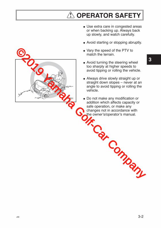
� Avoid turning the steering wheeltoo sharply at higher speeds toavoid tipping or rolling the vehicle.
� Always drive slowly straight up orstraight down slopes – never at anangle to avoid tipping or rolling thevehicle.
� Do not make any modification oraddition which affects capacity orsafe operation, or make anychanges not in accordance withthe owner’s/operator’s manual.
Y-2831
OPERATOR SAFETY!
©2019 Yamaha Golf-Car Com
pany
SAFETY CONSIDERATIONS
1
2
3
4
5
6
7
8
9
10
11
4-1 J0E
!
Like all machines, PTVs can causeinjury if improperly used or maintained.
Experience has shown that PTVsare safe when operated inaccordance with the safety warningsaffixed to every PTV.
DRIVER QUALIFICATIONS
Allow only authorized people tooperate PTV. It is recommended thatonly people who possess a validmotor vehicle driver’s license beallowed to operate PTV.
Do Not Operate PTVs When UnderThe Influence of Alcohol or Drugs
Do not operate PTVs when underthe influence of alcohol or drugs.Death or serious personal injurycan result from failing to complywith the warning instructions inthis manual.
HAZARD PREVENTIONDrivers should be mindful of roadhazards, and avoid dangeroussituations that may include thefollowing:
Steep Grades – Where steepgrades exist, restrict PTV todesignated roadway or path, anddescend slowly with foot on thebrake.
Descend steep grades slowly withfoot on brake. Death or seriouspersonal injury can result fromfailing to comply with the warninginstructions in this manual.
Sharp Turns, Blind Corners andBridge Approaches – Adhere to allwarning signs and take properprecautions to avoid the hazard.
Wet Areas – Wet grass may causea PTV to lose traction and mayaffect stability. Vehicle operatorsshould reduce speed in wet areas orduring periods of inclement weather.
©2019 Yamaha Golf-Car Com
pany

1
2
3
4
5
6
7
8
9
10
11
SAFETY CONSIDERATIONS
4-2J0E
!
� Loose Terrain – Avoid areas ofloose terrain which may cause aPTV to lose traction and affect stability. Take notice of conditionsand reduce speed when driving onuneven or loose terrain.
� Pedestrian Areas – Avoid areaswith pedestrian traffic or congestedareas whenever possible toprevent accidents. If it isimpractical to avoid these areas,always remember that pedestrianshave the right of way. Whenapproaching pedestrian orcongested area always reducespeed, drive slowly, use cautionand watch for pedestrians.
MAINTENANCE REQUIRED FOR PTVSAFETYPractice the following to help ensurethe safety of PTV occupants:
� Preventative Maintenance. Per-form all scheduled maintenance inaccordance with manufacturer’srecommendations to provide asafe, properly operating PTV.
� Personnel. Allow only qualified,trained and authorized personnelto inspect, adjust and maintainPTVs.
� Parts and Materials. Use onlyreplacement parts and materialsrecommended by the manufacturer.
� Ventilation. Properly ventilate allmaintenance and storage areas inaccordance with applicable firecodes and ordinances to avoid firehazards. Ventilation is required toremove hydrogen gas from electricpowered car storage areas duringthe charging process.
For electric powered PTVs, theamount of hydrogen gas emitted during charging depends on a number of factors, such as the condition of the batteries, the outputrate of the battery charger and theamount of time the batteries are oncharge. Because of the highlyvolatile nature of hydrogen gas andits propensity to rise and accumulateat the ceiling in pockets, a minimum of five air changes per hour is recommended. Consult applicablefire and safety codes for the specificventilation levels requirement, aswell as requirements for the use of explosion proof electrical apparatus.
©2019 Yamaha Golf-Car Com
pany
1
2
3
4
5
6
7
8
9
10
11
J0E
SAFETY CONSIDERATIONS!
SAFETY PRECAUTIONSDURING MAINTENANCEWhen performing maintenance, follow all safety instructions containedin the manufacturer’s operation andservice manuals, as well as thefollowing safety procedures:
� Properly immobilize PTV beforebeginning any maintenance toavoid any unexpected vehiclemovement.
� Properly block chassis beforeworking underneath PTV to avoidany unexpected vehicle movement.
� When working on the battery, donot smoke, or allow any sparks oropen flames near the vehicle, toavoid any fires or explosions.
� Before working on an electric PTV, disable the car’s electricalsystem in accordance with themanufacturer’s instructions toavoid electrical shock or damageto the electrical system.
� Use only properly insulated toolswhen working on electrically powered PTVs or around batteriesto avoid electrical shock ordamage to the electrical system.
� Maintain all safety devices includ-ing brakes, steering mechanisms,warning devices and governors, ina safe operating condition. Do notmodify these safety devices assupplied by the manufacturer.
� After each maintenance or repair,the car must be driven by a qualified, trained and authorizedperson – in an area free ofpedestrian traffic – to ensureproper operation and adjustment.
� Record all maintenance performedin a maintenance record log bydate, name of person performingmaintenance and type of mainte-nance. Periodically inspect mainte-nance log to ensure accurate andcomplete entries.
� Provide operator comment cardsto assist in identifying non-periodicmaintenance needs for specificPTVs.
� Maintain in a legible condition allnameplates, warnings and instructions provided by the manufacturer.
� If new nameplates, warnings orinstructions are needed, contactyour Yamaha dealer.
STORAGE AND BATTERY CHARGINGTake the following precautions toensure maintenance worker safety:
� Only use battery changing andcharging facilities and proceduresthat are in accordance with applic-able ordinances and regulations toavoid explosions, electrical shockor damage to the electricalsystem.
� Periodically inspect charging facili-ties and procedures to be certainthat applicable safety codes,regulations and procedures arebeing followed to avoid any firesor explosions.
4-3
©2019 Yamaha Golf-Car Com
pany
1
2
3
4
5
6
7
8
9
10
11
CONTROLS
5-1J0E
Y-283411
10
10
Y-2833
1
9
2
8
6 5
4
3
7
9
Y-2836
21
19
20
18
19
17 16
15
12
13
14
Y-2835
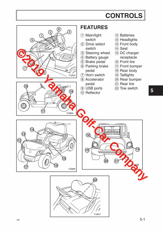
FEATURES1 Main/light
switch2 Drive select
switch3 Steering wheel4 Battery gauge5 Brake pedal6 Parking brake
pedal7 Horn switch8 Accelerator
pedal9 USB portsa Reflector
b Batteriesc Headlightsd Front bodye Seatf DC charger
receptacleg Front tire h Front bumperi Rear bodyj Taillightsk Rear bumperl Rear tirem Tow switch
Y-2837
22
©2019 Yamaha Golf-Car Com
pany
CONTROLS
1
2
3
4
5
6
7
8
9
10
11
5-2 J0E
Y-2838
BATTERY
ONOFF
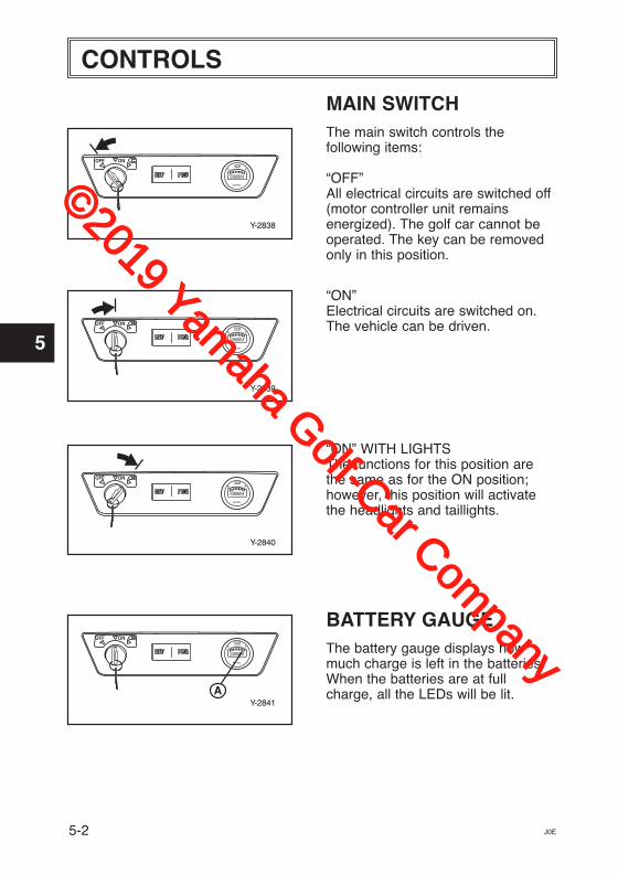
MAIN SWITCHThe main switch controls thefollowing items:
“OFF”All electrical circuits are switched off(motor controller unit remainsenergized). The golf car cannot beoperated. The key can be removedonly in this position.
“ON”Electrical circuits are switched on.The vehicle can be driven.
“ON” WITH LIGHTSThe functions for this position arethe same as for the ON position;however, this position will activatethe headlights and taillights.
BATTERY GAUGEThe battery gauge displays howmuch charge is left in the batteries.When the batteries are at fullcharge, all the LEDs will be lit.
Y-2839
ONOFF
BATTERY
Y-2840
BATTERY
ONOFF
Y-2841A
ONOFF
BATTERY
©2019 Yamaha Golf-Car Com
pany
1
2
3
4
5
6
7
8
9
10
11
CONTROLS
5-3J0E
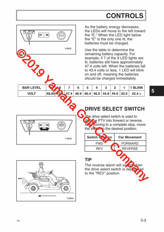
As the battery energy decreases,the LEDs will move to the left towardthe “E.” When the LED light belowthe “E” is the only one lit, thebatteries must be charged.
Use the table to determine theremaining battery capacity. Forexample, if 7 of the 9 LED lights arelit, batteries still have approximately47.4 volts left. When the batteries fallto 43.4 volts or less, 1 LED will blinkon and off, meaning the batteriesshould be charged immediately.
DRIVE SELECT SWITCHThe drive select switch is used to shift the PTV into forward or reverse.After coming to a complete stop, movethe switch to the desired position.
Switch Position Car Movement
FWD FORWARD
REV REVERSE
TIPThe reverse alarm will sound whenthe drive select switch is depressedto the “REV” position.
Y-2843
ONOFF
BATTERY
BAR LEVEL 9 8 7 6 5 4 3 2 1 1 BLINK
VOLT 48.95 47.8 47.4 46.9 46.4 46.0 44.8 44.0 43.5 43.4 >
Y-2844
BEEP
Y-2842
ONOFF
BATTERY
©2019 Yamaha Golf-Car Com
pany
CONTROLS
1
2
3
4
5
6
7
8
9
10
11
5-4 J0E
Y-22a
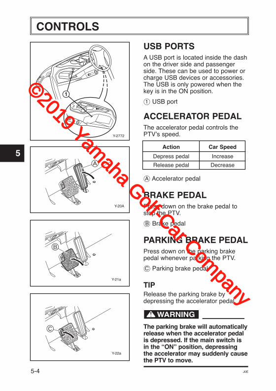
USB PORTSA USB port is located inside the dashon the driver side and passengerside. These can be used to power orcharge USB devices or accessories.The USB is only powered when thekey is in the ON position.
1 USB port
ACCELERATOR PEDALThe accelerator pedal controls thePTV’s speed.
Action Car Speed
Depress pedal Increase
Release pedal Decrease
å Accelerator pedal
BRAKE PEDALPress down on the brake pedal tostop the PTV.
∫ Brake pedal
PARKING BRAKE PEDALPress down on the parking brakepedal whenever parking the PTV.
ç Parking brake pedal
TIPRelease the parking brake bydepressing the accelerator pedal.
The parking brake will automaticallyrelease when the accelerator pedalis depressed. If the main switch isin the “ON” position, depressingthe accelerator may suddenly causethe PTV to move.
Y-21a
Y-20A
Y-2772
1
A
B
C
©2019 Yamaha Golf-Car Com
pany
1
2
3
4
5
6
7
8
9
10
11
CONTROLS
5-5J0E
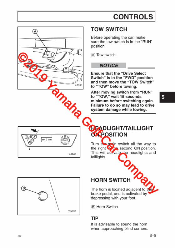
TOW SWITCHBefore operating the car, make sure the tow switch is in the “RUN”position.
å Tow switch
Ensure that the “Drive SelectSwitch” is in the “FWD” positionand then move the “TOW Switch”to “TOW” before towing.After moving switch from “RUN”to “TOW,” wait 15 secondsminimum before switching again.Failure to do so may lead to drivesystem damage while towing.
HEADLIGHT/TAILLIGHTON POSITION
Turn the main switch all the way tothe right to the second ON position.This will activate the headlights andtaillights.
HORN SWITCH
The horn is located adjacent to thebrake pedal, and is activated bydepressing with your foot.
∫ Horn Switch
TIPIt is advisable to sound the hornwhen approaching blind corners.
NOTICE
Y-2840
BATTERY
ONOFF
Y-901B
B
Y-1995
TOW
RUN
A
©2019 Yamaha Golf-Car Com
pany
PRE-OPERATION CHECKS
1
2
3
4
5
6
7
8
9
10
11
6-1 J0E
Y-905
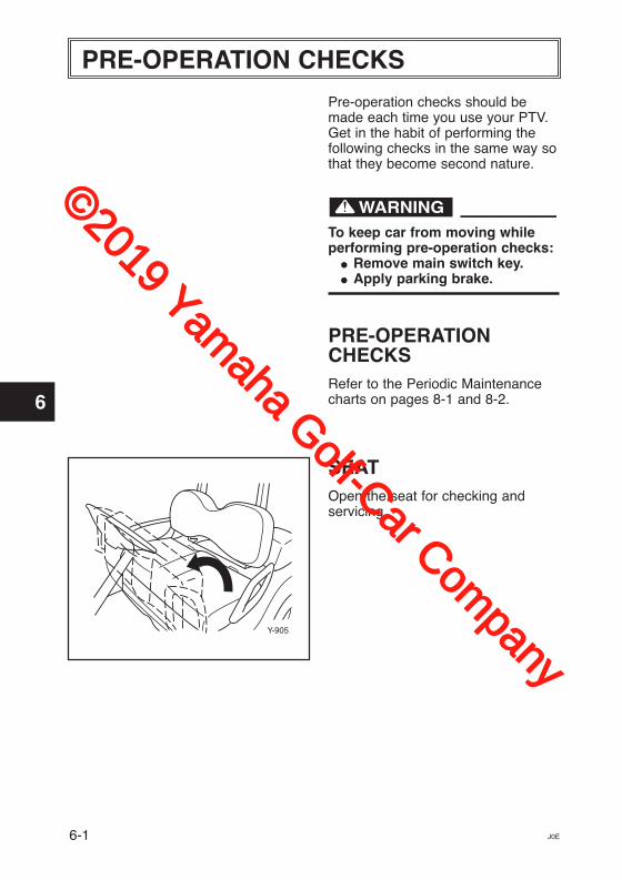
Pre-operation checks should bemade each time you use your PTV.Get in the habit of performing the following checks in the same way sothat they become second nature.
To keep car from moving whileperforming pre-operation checks: � Remove main switch key. � Apply parking brake.
PRE-OPERATIONCHECKSRefer to the Periodic Maintenancecharts on pages 8-1 and 8-2.
SEATOpen the seat for checking and servicing.
©2019 Yamaha Golf-Car Com
pany
1
2
3
4
5
6
7
8
9
10
11
PRE-OPERATION CHECKS
J0E
BATTERYCharge batteries before each use.See charging steps in Chapter 8,Maintenance.
Check that the batteries are heldsecurely in place to prevent the batteries from being damaged fromvibration or jarring. Also check thatno battery caps are missing to prevent battery acid from spillingfrom the battery. Check the batteryterminals for corrosion.
Battery electrolyte is poisonousand dangerous, causing severeburns, etc. It contains sulfuricacid. Avoid contact with skin, eyesor clothing. Ventilate whencharging or using in enclosedspace. Always shield eyes whenworking near batteries. KEEP OUTOF REACH OF CHILDREN.
TIRE CONDITION
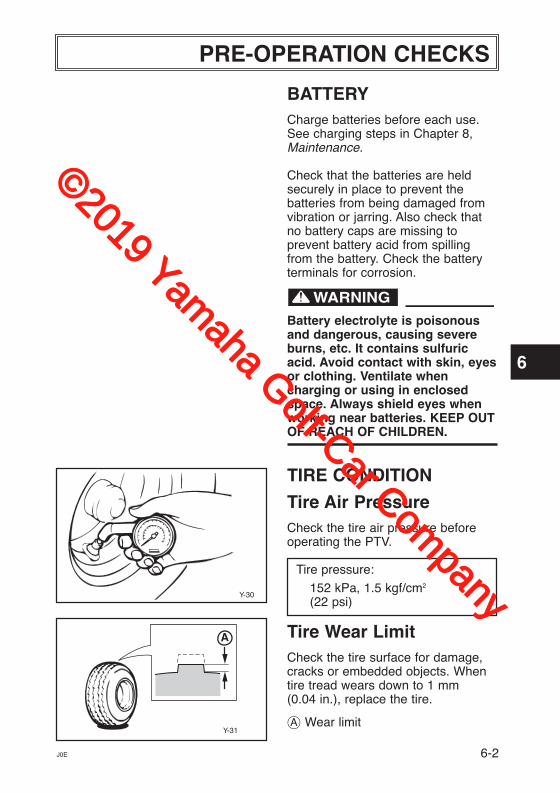
Tire Air PressureCheck the tire air pressure beforeoperating the PTV.
Tire pressure:
152 kPa, 1.5 kgf/cm2
(22 psi)
Tire Wear LimitCheck the tire surface for damage,cracks or embedded objects. Whentire tread wears down to 1 mm(0.04 in.), replace the tire.
å Wear limit
Y-30
A
Y-31
6-2
©2019 Yamaha Golf-Car Com
pany
PRE-OPERATION CHECKS
1
2
3
4
5
6
7
8
9
10
11
6-3
Y-20A
Y-2845
Y-2846
ONOFF
BATTERY
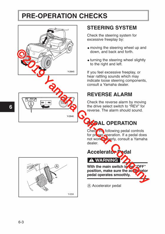
STEERING SYSTEMCheck the steering system forexcessive freeplay by:
� moving the steering wheel up and down, and back and forth.
� turning the steering wheel slightly to the right and left.
If you feel excessive freeplay, orhear rattling sounds which mayindicate loose steering components,consult a Yamaha dealer.
REVERSE ALARMCheck the reverse alarm by movingthe drive select switch to “REV” forreverse. The alarm should sound.
PEDAL OPERATIONCheck the following pedal controlsfor proper operation. If a pedal doesnot work properly, consult a Yamahadealer.
Accelerator Pedal
With the main switch in the “OFF”position, make sure the acceleratorpedal operates smoothly.
å Accelerator pedal
A
©2019 Yamaha Golf-Car Com
pany
1
2
3
4
5
6
7
8
9
10
11
PRE-OPERATION CHECKS
6-4J0E
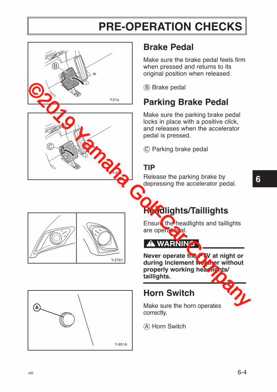
Brake PedalMake sure the brake pedal feels firmwhen pressed and returns to its original position when released.
∫ Brake pedal
Parking Brake PedalMake sure the parking brake pedallocks in place with a positive click,and releases when the acceleratorpedal is pressed.
ç Parking brake pedal
TIPRelease the parking brake bydepressing the accelerator pedal.
Headlights/TaillightsEnsure the headlights and taillightsare operational.
Never operate the PTV at night orduring inclement weather withoutproperly working headlights/taillights.
Horn SwitchMake sure the horn operatescorrectly.
å Horn Switch
Y-22a
Y-2761
Y-901A
A
Y-21a
B
C
©2019 Yamaha Golf-Car Com
pany
OPERATION
1
2
3
4
5
6
7
8
9
10
11
7-1 J0E
Y-2842
ONOFF
BATTERY
Y-20A
BODY AND CHASSISBefore each use, visually inspect thePTV body and chassis for damagedand/or missing parts.
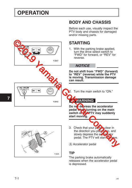
STARTING1. With the parking brake applied,
turn the drive select switch to“FWD” for forward, or “REV” forreverse.
Do not shift from “FWD” (forward)to “REV” (reverse) while the PTVis moving. Transmission damagecan result.
2. Turn the main switch to “ON.”
Do not depress the acceleratorpedal when turning on the mainswitch or the PTV may suddenlystart moving.
3. Check that your path is clear inthe direction you plan to go, andslowly depress the acceleratorpedal. The PTV will start to move.
å Accelerator pedal
TIPThe parking brake automaticallyreleases when the accelerator pedalis depressed.
NOTICE
Y-2847
ONOFF
BATTERY
A
©2019 Yamaha Golf-Car Com
pany
1
2
3
4
5
6
7
8
9
10
11
OPERATION
7-2J0E
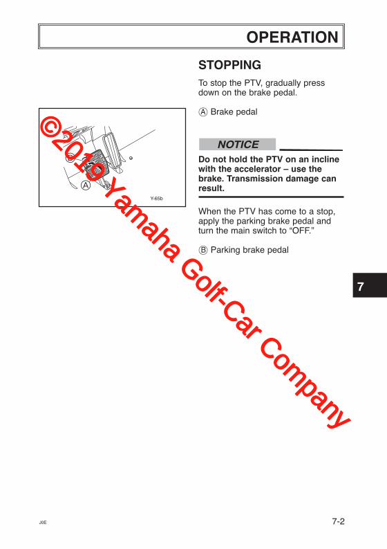
STOPPINGTo stop the PTV, gradually pressdown on the brake pedal.
å Brake pedal
Do not hold the PTV on an inclinewith the accelerator – use thebrake. Transmission damage canresult.
When the PTV has come to a stop,apply the parking brake pedal andturn the main switch to “OFF.”
∫ Parking brake pedal
NOTICE
Y-65b
A
B
©2019 Yamaha Golf-Car Com
pany
MAINTENANCE
1
2
3
4
5
6
7
8
9
10
11
8-1 J0E
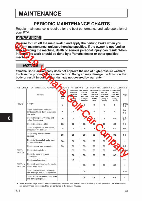
PERIODIC MAINTENANCE CHARTSRegular maintenance is required for the best performance and safe operation ofyour PTV.
Be sure to turn off the main switch and apply the parking brake when youperform maintenance, unless otherwise specified. If the owner is not familiarwith servicing the machine, death or serious personal injury can result. Whenin doubt the work should be done by a Yamaha dealer or other qualifiedmechanic.
Yamaha Golf-Car Company does not approve the use of high-pressure washersto clean the products they manufacture. Doing so may damage the finish on thebody or result in doing other damage not covered by warranty.
NOTICE
DailyPre-
Opera-tion
20 hours100 miles160 kms(EveryMonth)
125 hrs600 mls
1000 kms(Every 6months)
250 hrs1200 mls2000 kms
(EveryYear)
500 hrs2500 mls4000 kms(Every 2years)
1000 hrs5000 mls8000 kms(Every 4years)
PageRemarks
40 rounds 250 rounds 500 rounds 1000 rounds 2000 rounds
ChargePRE-OP
EVERYMONTH
EVERY 6MONTHS
4-3/8-5/8-6
6-28-3/
6-4/8-11
*
*
*
*
—
6-3
6-3
6-2
7-1
8-3/8-4
* Items without a page number reference should be serviced by a Yamaha dealer or other qualified mechanic. This manual doesnot contain these procedures. They are contained in the Service Manual.
CS - CHECK CA - CHECK AND ADJUST R - REPLACE S - SERVICE CL - CLEAN AND LUBRICATE L - LUBRICATE
Clean battery tops, check fortightness of hold-down screws andterminals
Check brake pedal freeplay andadjust if necessary
Check steering operation
Check tire pressure, tread depth,tire surface for damage
Check body and chassis for damage
Check tightness of all bolts, nuts,screws and rivets
Check for loose or brokenconnections
Check all wire insulation for cracksand/or worn spots
Check shock absorbers for oil leaksand damaged springs
Check pedal operation
Check reverse alarm operation
Check electrolyte level
S
S
CS
CS
CS
S
S
CA
CA
CS
CS
S
S
CA
CA
CS
S
S
CA
CA
CS
S
S
CA
CA
CS
S
S
CA
CA
CS
CS CS CS CS CS CS
CS CS CS CS CS CS
CS CS CS CS CS CS
CS CS CS CS CS
CS CS CS CS CS
CS CS CS CS
8-20Check brake cables for abrasionand damage, and check operation
CS
CS CS CS CS
©2019 Yamaha Golf-Car Com
pany
1
2
3
4
5
6
7
8
9
10
11
MAINTENANCE
8-2J0E
DailyPre-
Opera-tion
20 hours100 miles160 kms(EveryMonth)
125 hrs600 mls
1000 kms(Every 6months)
250 hrs1200 mls2000 kms
(EveryYear)
500 hrs2500 mls4000 kms(Every 2years)
1000 hrs5000 mls8000 kms(Every 4years)
PageRemarks
40 rounds 250 rounds 500 rounds 1000 rounds 2000 rounds
EVERYYEAR
EVERY 4YEARS
8-10/*
*
*
—
8-9
8-12
*
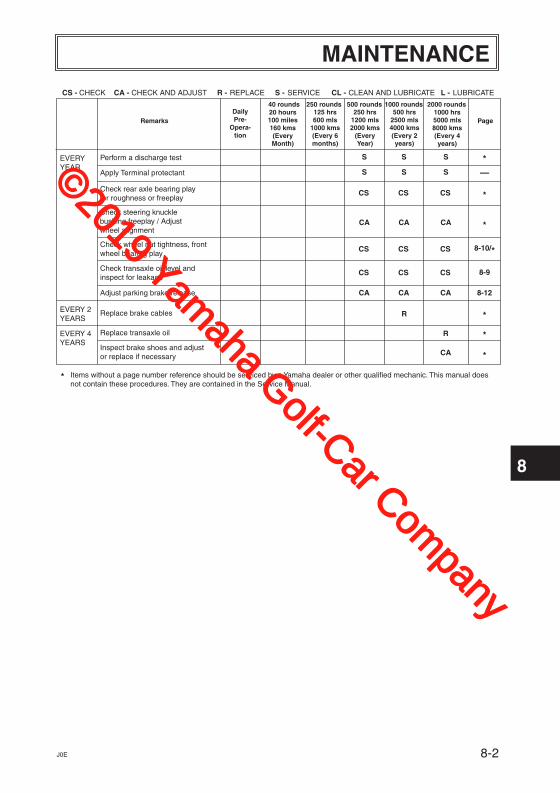
* Items without a page number reference should be serviced by a Yamaha dealer or other qualified mechanic. This manual doesnot contain these procedures. They are contained in the Service Manual.
CS - CHECK CA - CHECK AND ADJUST R - REPLACE S - SERVICE CL - CLEAN AND LUBRICATE L - LUBRICATE
Check wheel nut tightness, frontwheel bearing play
Check transaxle oil level andinspect for leakage
Perform a discharge test
Apply Terminal protectant
Inspect brake shoes and adjustor replace if necessary
Replace transaxle oil
S
S
S
S
S
S
CA
CS CS CS
CS CS CS
CS CS CS
*
*
Check rear axle bearing playfor roughness or freeplay
CA CA CA
R
EVERY 2YEARS *Replace brake cables R
Check steering knucklebushing freeplay / Adjustwheel alignment
Adjust parking brake release CA CA CA
©2019 Yamaha Golf-Car Com
pany
MAINTENANCE
1
2
3
4
5
6
7
8
9
10
11
8-3 J0E
Battery Care
Battery electrolyte is poisonousand dangerous, causing severeburns, etc. It contains sulfuric acid.Avoid contact with skin, eyes orclothing.Antidote:EXTERNAL: Flush with water. INTERNAL: Drink large quantities ofwater or milk. Follow with milk ofmagnesia, beaten egg or vegetableoil. Call physician immediately.EYES: Flush with water for 15 minutes and get prompt medical attention.Batteries produce explosive gases.Keep sparks, flame, cigarettes, etc.,away.Ventilate when charging or using inan enclosed space. Always shieldeyes when working near batteries.KEEP OUT OF REACH OF CHILDREN.
Six 8-volt deep cycle batteries provide power for your electric PTVand must be properly maintained andrecharged for maximum performanceand service life.
To maintain your batteries:
1. Clean the tops of the batterieswith a solution of baking sodaand water, as necessary, toremove corrosion.
Do not allow cleaning solution toenter battery cells. Serious batterydamage can result.
2. Check the fluid level before andafter charging.
NOTICE
©2019 Yamaha Golf-Car Com
pany
1
2
3
4
5
6
7
8
9
10
11
MAINTENANCE
8-4J0E
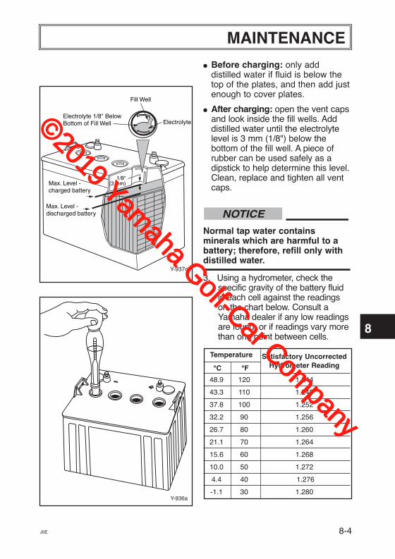
� Before charging: only adddistilled water if fluid is below thetop of the plates, and then add justenough to cover plates.
� After charging: open the vent capsand look inside the fill wells. Adddistilled water until the electrolytelevel is 3 mm (1/8") below thebottom of the fill well. A piece ofrubber can be used safely as adipstick to help determine this level.Clean, replace and tighten all ventcaps.
Normal tap water contains minerals which are harmful to abattery; therefore, refill only withdistilled water.
3. Using a hydrometer, check thespecific gravity of the battery fluidin each cell against the readingson the chart below. Consult aYamaha dealer if any low readingsare found, or if readings vary morethan one point between cells.
Temperature Satisfactory Uncorrected
°C °F Hydrometer Reading
48.9 120 1.244
43.3 110 1.248
37.8 100 1.252
32.2 90 1.256
26.7 80 1.260
21.1 70 1.264
15.6 60 1.268
10.0 50 1.272
4.4 40 1.276
-1.1 30 1.280
NOTICE
Y-936a
1/8"(3 mm)
Electrolyte 1/8" BelowBottom of Fill Well
Max. Level - discharged battery
Max. Level - charged battery
Fill Well
Electrolyte
Y-937c
©2019 Yamaha Golf-Car Com
pany
MAINTENANCE
1
2
3
4
5
6
7
8
9
10
11
8-5 J0E
Y-2838
BATTERY
ONOFF
Battery Charging
Read and understand the owner’smanual provided with your PTV’sbattery charger before chargingbatteries. Death or seriouspersonal injury can result fromfailing to comply with the warninglabels in this manual.
Explosive hydrogen gas is produced while batteries are beingcharged. Only charge batteries inwell-ventilated areas (a minimum offive air changes per hour isrecommended). Death or seriouspersonal injury can result fromfailing to comply with the warninglabels in this manual.
To charge the batteries in your PTV, follow the instructionscontained in your battery charger’sowner’s manual. The following is asummary of the charging steps.
Do not attempt to recharge yourPTV’s batteries without thoroughlyreading and understanding theowner’s manual provided withyour charger.
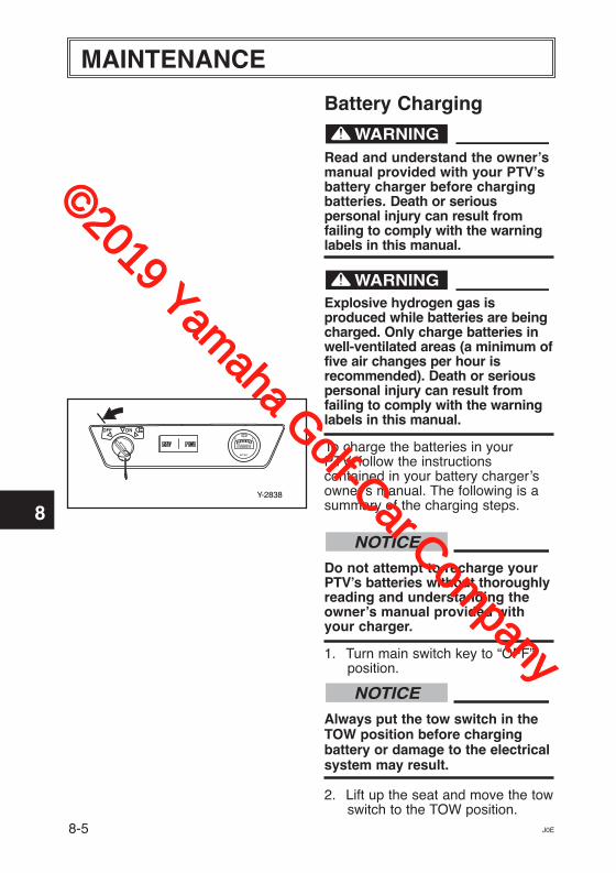
1. Turn main switch key to “OFF”position.
Always put the tow switch in theTOW position before chargingbattery or damage to the electricalsystem may result.
2. Lift up the seat and move the towswitch to the TOW position.
NOTICE
NOTICE
©2019 Yamaha Golf-Car Com
pany
1
2
3
4
5
6
7
8
9
10
11
MAINTENANCE
8-6J0E
Use only battery chargers that arerated for use with 48-volt YamahaPTVs. Serious battery damage canresult. Thoroughly read andunderstand the user manualsupplied with your 48-voltcharger.
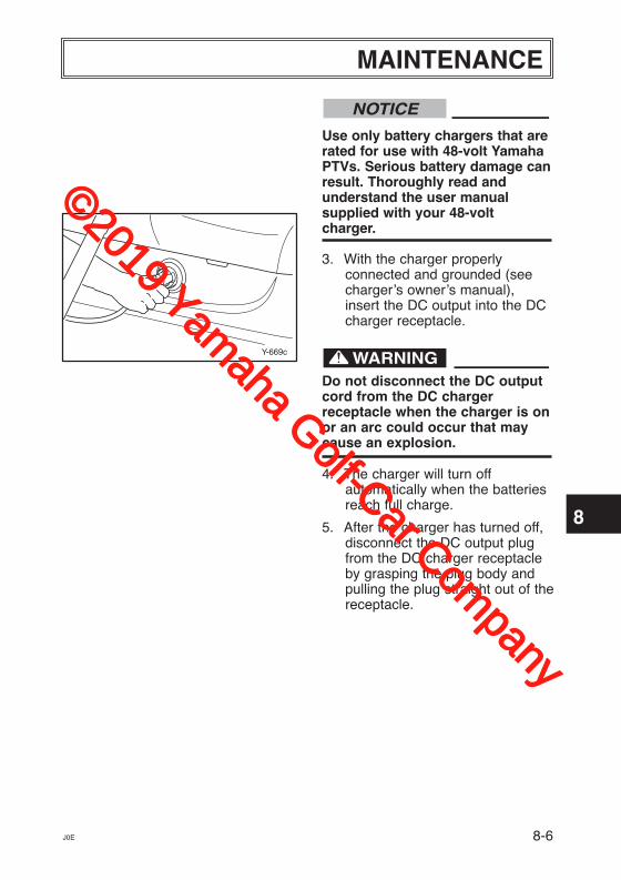
3. With the charger properlyconnected and grounded (seecharger’s owner’s manual),insert the DC output into the DCcharger receptacle.
Do not disconnect the DC outputcord from the DC chargerreceptacle when the charger is onor an arc could occur that maycause an explosion.
NOTICE
Y-669c
4. The charger will turn offautomatically when the batteriesreach full charge.
5. After the charger has turned off,disconnect the DC output plugfrom the DC charger receptacleby grasping the plug body andpulling the plug straight out of thereceptacle.
©2019 Yamaha Golf-Car Com
pany
MAINTENANCE
1
2
3
4
5
6
7
8
9
10
11
8-7 J0E
Y-751D
B CA
Y-672h
Battery Installation
When working with batteries, do notput wrenches or other metal objectsacross the battery terminals. An arccan occur causing explosion of thebattery.
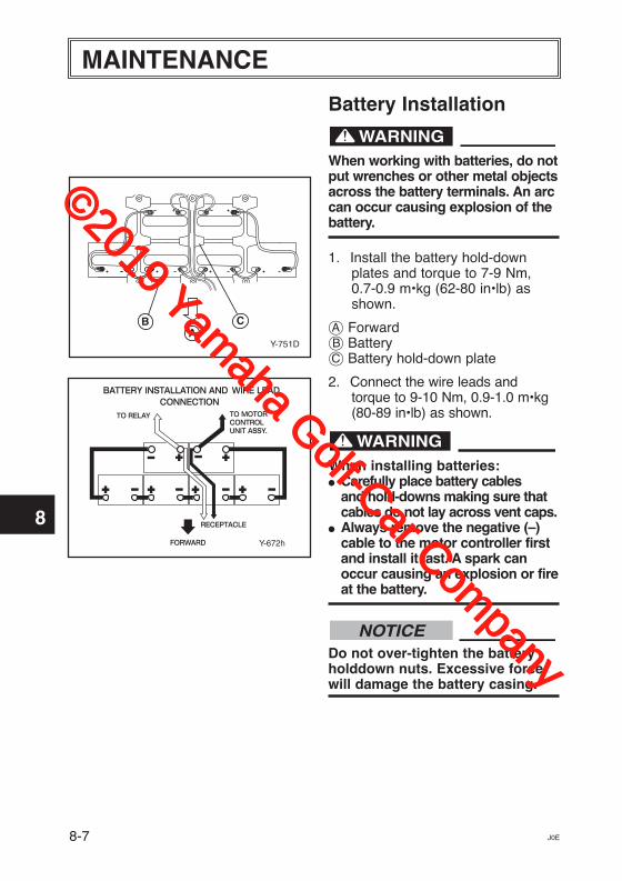
1. Install the battery hold-downplates and torque to 7-9 Nm, 0.7-0.9 m•kg (62-80 in•lb) asshown.
å Forward∫ Batteryç Battery hold-down plate
2. Connect the wire leads andtorque to 9-10 Nm, 0.9-1.0 m•kg(80-89 in•lb) as shown.
When installing batteries:� Carefully place battery cables
and hold-downs making sure thatcables do not lay across vent caps.
� Always remove the negative (–)cable to the motor controller firstand install it last. A spark canoccur causing an explosion or fireat the battery.
Do not over-tighten the batteryholddown nuts. Excessive forcewill damage the battery casing.
NOTICE
©2019 Yamaha Golf-Car Com
pany
1
2
3
4
5
6
7
8
9
10
11
MAINTENANCE
J0E
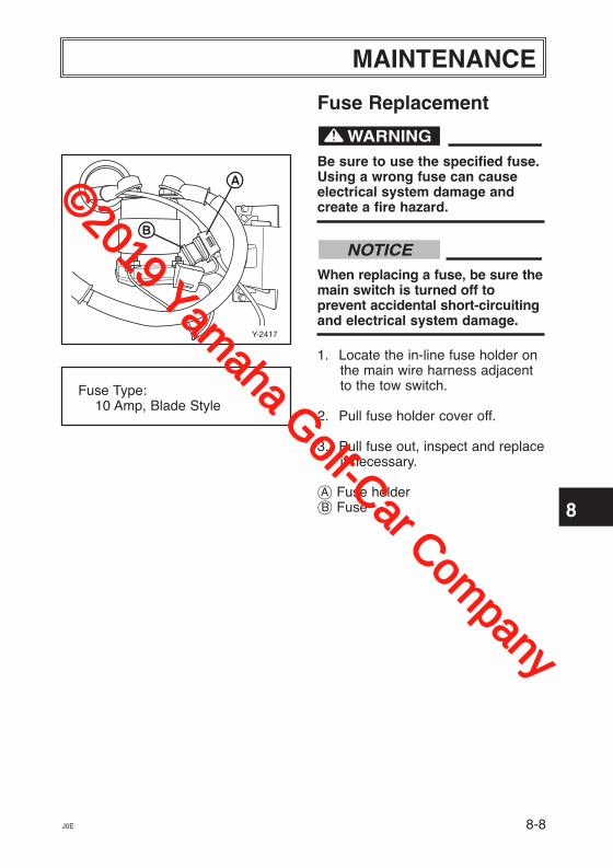
Fuse Replacement
Be sure to use the specified fuse.Using a wrong fuse can causeelectrical system damage andcreate a fire hazard.
When replacing a fuse, be sure themain switch is turned off toprevent accidental short-circuitingand electrical system damage.
1. Locate the in-line fuse holder onthe main wire harness adjacentto the tow switch.
2. Pull fuse holder cover off.
3. Pull fuse out, inspect and replaceif necessary.
å Fuse holder∫ Fuse
NOTICE
Fuse Type:10 Amp, Blade Style
B
A
Y-2417
8-8
©2019 Yamaha Golf-Car Com
pany
1
2
3
4
5
6
7
8
9
10
11
8-9 J0E
MAINTENANCE
Multi-Charge Steps: Ensures aconsistent and repeatable charge.
Step 1: Pre-test: Tests severalconditions before charging begins.If a problem is detected, charging isterminated.
Step 2: Constant Current Step:Battery is charged with full ratedoutput current, restoring up to 80%of charge.
Step 3: Constant Voltage Step:Regulated voltage “equalizes”individual battery cells, resulting infull charge delivered to the battery.
Step 4: Topping Off Step: Batterypack is brought slowly to full chargewithout excess gassing.
Step 5: Storage: Every 14th dayand if voltage becomes less than48V, charger restarts cycle torefresh batteries in storage.
Automatic Battery Equalization(Boosting): Automatically boostsbattery pack when individual cell-voltages are not balanced andrestores pack capacity.
BATTERY CHARGER
Prepare for EmergenciesBe prepared for possible injury or fire.Keep the following items handy:
� First aid kit � Fire extinguisher � Emergency phone numbers
Read the text located on the case ofthe charger before operating or usingthe charger.
Features Switch-Mode Design: High-efficiency operation with smooth,ripple-free DC output.
10-LED Display: Displays state ofcharge and charge error conditions.
Charge Protection: Protects fromimproper connection, overload andexcessive temperatures.Programmed safety features includecharge time monitoring and overtemperature protection.
Charge Algorithm: I-E-I - constantcurrent/constant voltage/constantcurrent charge profile.
Pre-Test: Performs severaldiagnostic tests before chargingbegins.
©2019 Yamaha Golf-Car Com
pany
1
2
3
4
5
6
7
8
9
10
11
J0E
MAINTENANCE
The output of chargers withgreater than 48 volts may pose anenergy and/or shock hazard undernormal use.
Installation The AC line connected to the chargermust be capable of supplying 12Amperes to the charger. AVOIDconnecting a charger and anotherdevice to a single 15A/20A circuit orthe circuit may become overloaded.Also, maximum Ampere variesdepending on AC voltage. Pleaserefer to “AC Input” in GeneralSpecifications.
RISK OF FIRE - Use this chargeronly on circuits with a 15-amp orhigher branch circuit protection(circuit breaker or fuse) inaccordance with the nationalelectrical code, ANSI/NFPA 70 andall applicable local codes andordinances.
When using an extension cord,use only a grounded, 3-wire, 12-AWG cord no longer than 15 m(50'). The use of an improperextension cord could result in arisk of a fire or electric shock.
8-10
©2019 Yamaha Golf-Car Com
pany
1
2
3
4
5
6
7
8
9
10
11
8-11 J0E
MAINTENANCE
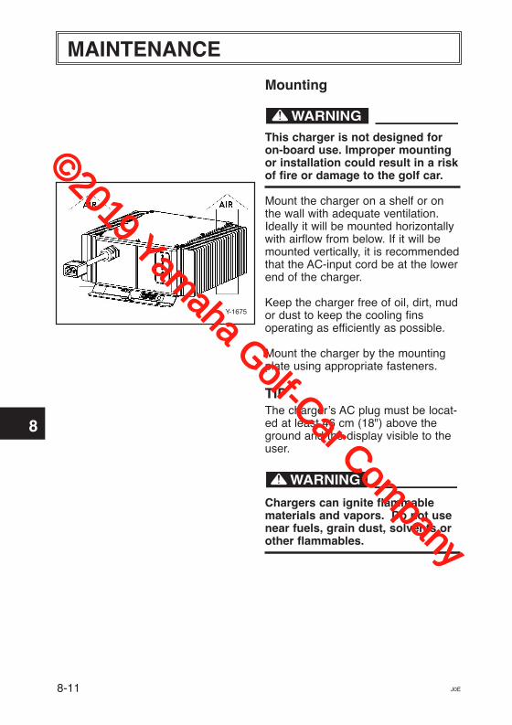
Mounting
This charger is not designed foron-board use. Improper mountingor installation could result in a riskof fire or damage to the golf car.
Mount the charger on a shelf or onthe wall with adequate ventilation.Ideally it will be mounted horizontallywith airflow from below. If it will bemounted vertically, it is recommendedthat the AC-input cord be at the lowerend of the charger.
Keep the charger free of oil, dirt, mudor dust to keep the cooling finsoperating as efficiently as possible.
Mount the charger by the mountingplate using appropriate fasteners.
TIPThe charger’s AC plug must be locat-ed at least 46 cm (18") above theground and the display visible to theuser.
Chargers can ignite flammablematerials and vapors. Do not usenear fuels, grain dust, solvents orother flammables.
Y-1675
©2019 Yamaha Golf-Car Com
pany
1
2
3
4
5
6
7
8
9
10
11
J0E
MAINTENANCE
Charging
To reduce the risk of an electricshock, connect only to a properlygrounded, single-phase (3-wire)outlet. Also, refer to groundinginstructions.
Risk of electric shock! Do nottouch any uninsulated parts of thecharger output plug, DC chargerreceptacle or battery terminals.
Surfaces may be hot. To avoid riskof burns, do not touch.
GroundingThe battery charger must begrounded to reduce the risk of electricshock. The charger is equipped witha 3-prong AC cord set. The AC cordset must be connected to anappropriate receptacle that is properlyinstalled and grounded in accordancewith the National Electrical Code andall local codes and ordinances.
Improper connection of theequipment-grounding conductorcan result in a risk of an electricshock.
The conductor with insulation thathas an outer surface that is green,with or without yellow stripe(s), is theequipment-grounding conductor. Ifrepair or replacement of the charger’sAC cord set is necessary, do notconnect the equipment-groundingconnector to a live terminal.
8-12
©2019 Yamaha Golf-Car Com
pany
1
2
3
4
5
6
7
8
9
10
11
J0E
MAINTENANCE
Visually and manually inspect toverify that the DC output cord,plug and battery chargingreceptacle are in good workingcondition before each and everyuse. Do not use the charger underany of the following conditions: � The DC charging receptacle does
not grip the DC cord set plugtightly, is loose or does not makea good electrical connection.
� The DC cord set plug orcharging receptacle feels hotterthan normal.
� The DC cord set plug orcharging receptacle contacts arebent, corroded, or are dark orbluish in appearance.
� The DC cord set plug, cords,receptacle or equipment-charging wiring are cut, worn,broken or have any exposedconductors.
� The DC cord plug, cords, chargeror receptacles are damaged ordistressed in any way.
Using the charger with any of theabove symptoms could result in afire, property damage or personalinjury.
8-13
Charge only 48-volt batterysystems manufactured by TrojanBattery Company. Damage to thecharger and batteries may result ifthis charger is used on the wrongbattery type.
NOTICE
Do not disconnect the DC cord setplug from the DC chargerreceptacle when the charger is on.If the charger must be stopped,first disconnect the AC powersupply cord from its AC outlet, andthen disconnect the charger DCcord set plug from the DC chargerreceptacle.
Whenever removing AC or DC cordset plugs from receptacles, pullfrom the plug body and not fromtheir respective cords.
The instructions printed on thecharger (shown below) are for dailyreference. The charger is factorypreset for use with Trojan 48-volt golfcar batteries.
©2019 Yamaha Golf-Car Com
pany
1
2
3
4
5
6
7
8
9
10
11
J0E 8-14
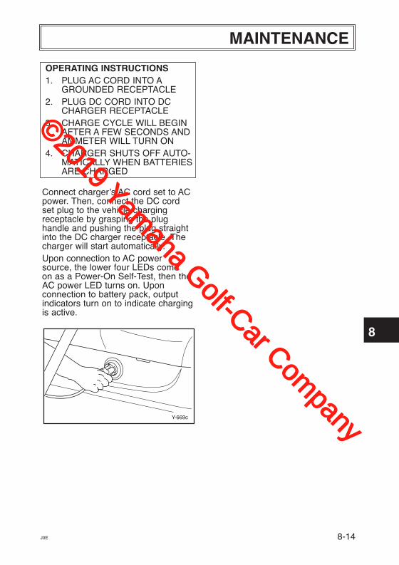
OPERATING INSTRUCTIONS1. PLUG AC CORD INTO A
GROUNDED RECEPTACLE2. PLUG DC CORD INTO DC
CHARGER RECEPTACLE3. CHARGE CYCLE WILL BEGIN
AFTER A FEW SECONDS ANDAMMETER WILL TURN ON
4. CHARGER SHUTS OFF AUTO-MATICALLY WHEN BATTERIESARE CHARGED
Connect charger’s AC cord set to ACpower. Then, connect the DC cord set plug to the vehicle chargingreceptacle by grasping the plughandle and pushing the plug straightinto the DC charger receptacle. Thecharger will start automatically. Upon connection to AC powersource, the lower four LEDs come on as a Power-On Self-Test, then theAC power LED turns on. Uponconnection to battery pack, outputindicators turn on to indicate chargingis active.
Y-669c
MAINTENANCE
©2019 Yamaha Golf-Car Com
pany
1
2
3
4
5
6
7
8
9
10
11
J0E8-15
MAINTENANCE
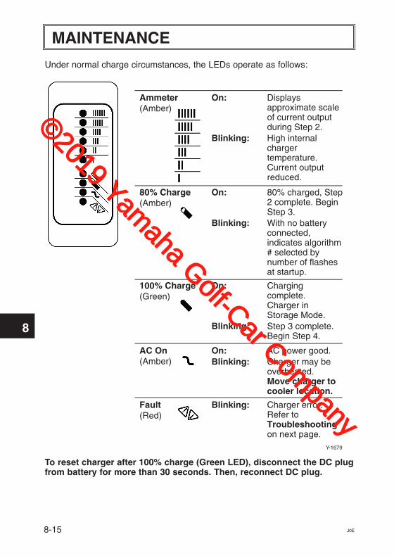
Under normal charge circumstances, the LEDs operate as follows:
To reset charger after 100% charge (Green LED), disconnect the DC plugfrom battery for more than 30 seconds. Then, reconnect DC plug.
Ammeter(Amber)
On: Displaysapproximate scaleof current outputduring Step 2.
Blinking: High internalchargertemperature.Current outputreduced.
80% Charge(Amber)
On: 80% charged, Step 2 complete. BeginStep 3.
Blinking: With no batteryconnected,indicates algorithm# selected bynumber of flashesat startup.
100% Charge(Green)
On: Charging complete.Charger inStorage Mode.
Blinking: Step 3 complete.Begin Step 4.
AC On(Amber)
On: AC power good.
Fault(Red)
Blinking: Charger error.Refer toTroubleshootingon next page.
Blinking: Charger may beoverheated.Move charger tocooler location.
Y-1679
©2019 Yamaha Golf-Car Com
pany
1
2
3
4
5
6
7
8
9
10
11
J0E 8-16
MAINTENANCE
Troubleshooting1. LED Error Codes (For Battery Condition)
Incorrect reassembly may result in a risk of electric shock or fire. Thefollowing procedures are intended only to determine if a malfunction mayexist in the charger.
To reduce the risk of electric shock, always disconnect the charger’s AC cordset plug from AC power and its DC cord set plug from batteries beforeattempting any maintenance or cleaning.
Do not operate the charger if it is malfunctioning. Personal injury or propertydamage could result.
©2019 Yamaha Golf-Car Com
pany
1
2
3
4
5
6
7
8
9
10
11
J0E8-17
MAINTENANCE
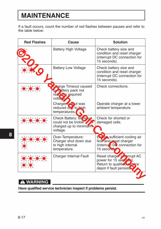
If a fault occurs, count the number of red flashes between pauses and refer tothe table below:
Have qualified service technician inspect if problems persist.
Red Flashes Cause Solution
Battery High Voltage Check battery size andcondition and reset charger(interrupt DC connection for15 seconds).
Battery Low Voltage Check battery size andcondition and reset charger(interrupt DC connection for15 seconds).
Charge Timeout causedby battery pack notreaching requiredvoltage.
Charger output wasreduced due to hightemperatures.
Check connections.
Operate charger at a lowerambient temperature.
Check Battery: Batterycould not be tricklecharged up to minimumvoltage.
Check for shorted ordamaged cells.
Over-Temperature:Charger shut down dueto high internaltemperature.
Ensure sufficient cooling airflow and reset charger(interrupt DC connection for15 seconds).
Charger Internal Fault Reset charger (interrupt ACpower for 15 seconds).Return to qualified servicedepot if fault persists.
©2019 Yamaha Golf-Car Com
pany
1
2
3
4
5
6
7
8
9
10
11
J0E 8-18
MAINTENANCE
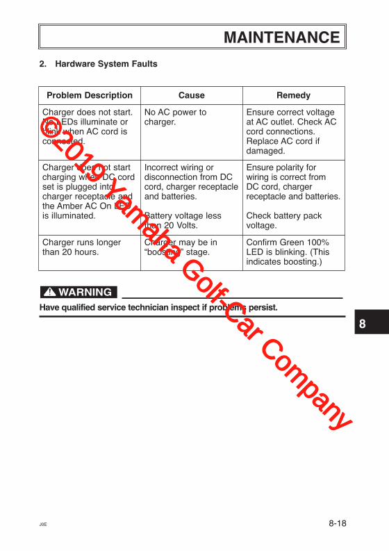
2. Hardware System Faults
Have qualified service technician inspect if problems persist.
Problem Description Cause Remedy
Charger does not start.No LEDs illuminate orblink when AC cord isconnected.
No AC power tocharger.
Ensure correct voltageat AC outlet. Check ACcord connections.Replace AC cord ifdamaged.
Charger does not startcharging when DC cordset is plugged intocharger receptacle andthe Amber AC On LEDis illuminated.
Incorrect wiring ordisconnection from DCcord, charger receptacleand batteries.
Battery voltage lessthan 20 Volts.
Ensure polarity forwiring is correct fromDC cord, chargerreceptacle and batteries.
Check battery packvoltage.
Charger runs longerthan 20 hours.
Charger may be in“boosting” stage.
Confirm Green 100%LED is blinking. (Thisindicates boosting.)
©2019 Yamaha Golf-Car Com
pany
MAINTENANCE
1
2
3
4
5
6
7
8
9
10
11
8-19 J0E
Y-2739
1
2
Y-2278b
3
4
Y-2739
1
2
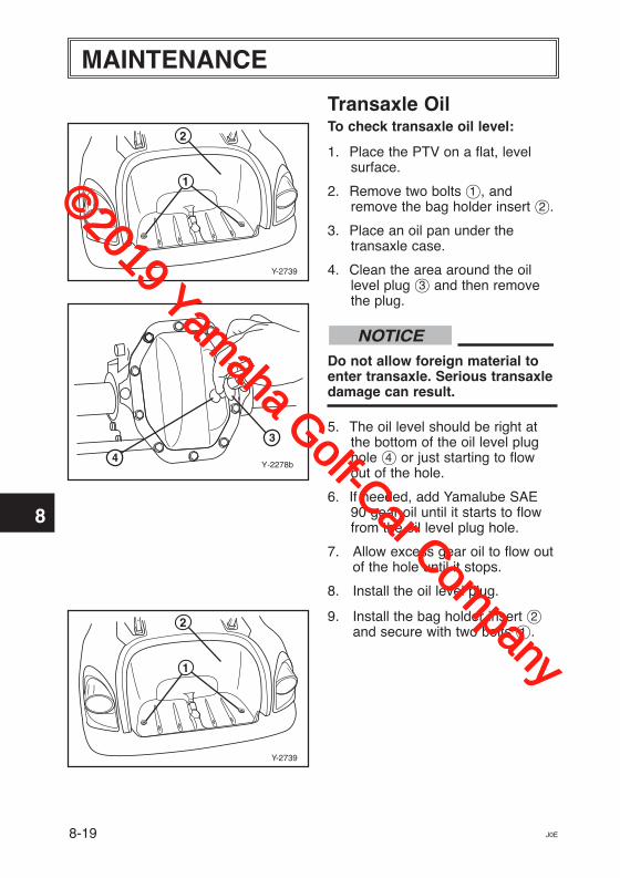
Transaxle OilTo check transaxle oil level:
1. Place the PTV on a flat, levelsurface.
2. Remove two bolts 1, andremove the bag holder insert 2.
3. Place an oil pan under thetransaxle case.
4. Clean the area around the oillevel plug 3 and then removethe plug.
Do not allow foreign material toenter transaxle. Serious transaxledamage can result.
5. The oil level should be right atthe bottom of the oil level plughole 4 or just starting to flowout of the hole.
6. If needed, add Yamalube SAE90 gear oil until it starts to flowfrom the oil level plug hole.
7. Allow excess gear oil to flow outof the hole until it stops.
8. Install the oil level plug.
9. Install the bag holder insert 2and secure with two bolts 1.
NOTICE
©2019 Yamaha Golf-Car Com
pany
1
2
3
4
5
6
7
8
9
10
11
MAINTENANCE
J0E
Y-57
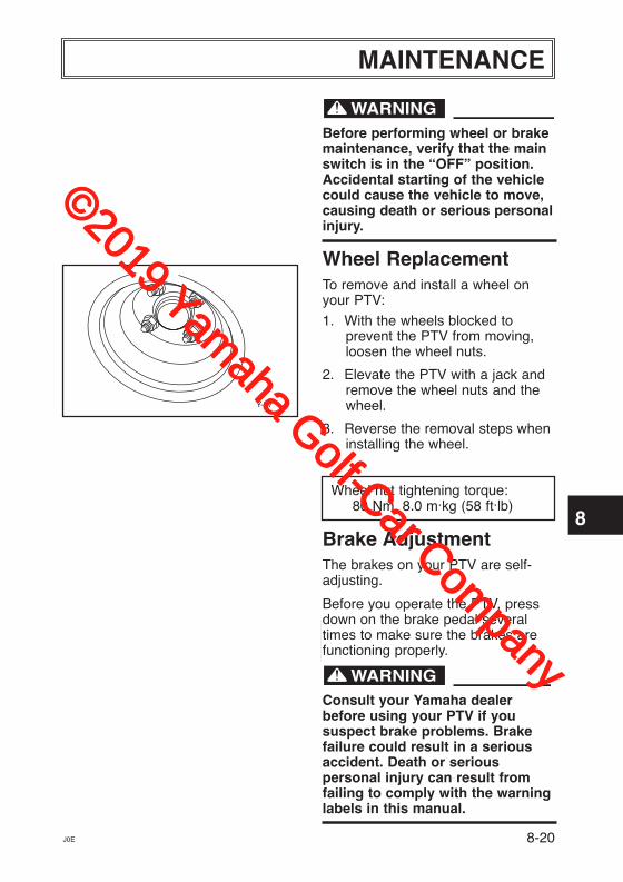
Before performing wheel or brakemaintenance, verify that the mainswitch is in the “OFF” position.Accidental starting of the vehiclecould cause the vehicle to move,causing death or serious personalinjury.
Wheel ReplacementTo remove and install a wheel onyour PTV:
1. With the wheels blocked to prevent the PTV from moving,loosen the wheel nuts.
2. Elevate the PTV with a jack andremove the wheel nuts and thewheel.
3. Reverse the removal steps wheninstalling the wheel.
Wheel nut tightening torque:80 Nm, 8.0 m.kg (58 ft.lb)
Brake Adjustment The brakes on your PTV are self-adjusting.
Before you operate the PTV, pressdown on the brake pedal severaltimes to make sure the brakes arefunctioning properly.
Consult your Yamaha dealerbefore using your PTV if you suspect brake problems. Brakefailure could result in a seriousaccident. Death or seriouspersonal injury can result fromfailing to comply with the warninglabels in this manual.
8-20
©2019 Yamaha Golf-Car Com
pany
MAINTENANCE
1
2
3
4
5
6
7
8
9
10
11
8-21
B A
Y-2281
J0E
Y-61c
Y-62b
7
1817
1615
1413
1211
109
8
a
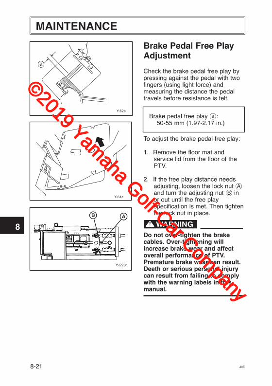
Brake Pedal Free PlayAdjustment
Check the brake pedal free play bypressing against the pedal with twofingers (using light force) andmeasuring the distance the pedaltravels before resistance is felt.
Brake pedal free play Å:50-55 mm (1.97-2.17 in.)
To adjust the brake pedal free play:
1. Remove the floor mat and service lid from the floor of thePTV.
2. If the free play distance needsadjusting, loosen the lock nut åand turn the adjusting nut ∫ inor out until the free playspecification is met. Then tightenthe lock nut in place.
Do not over-tighten the brakecables. Over-tightening willincrease brake wear and affectoverall performance of PTV.Premature brake wear can result.Death or serious personal injurycan result from failing to complywith the warning labels in thismanual.
©2019 Yamaha Golf-Car Com
pany
1
2
3
4
5
6
7
8
9
10
11
MAINTENANCE
8-22J0E
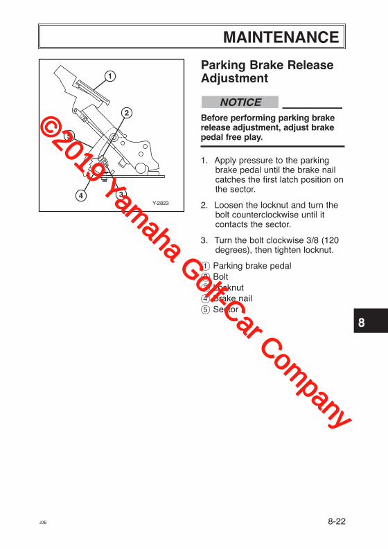
Parking Brake ReleaseAdjustment
Before performing parking brakerelease adjustment, adjust brakepedal free play.
1. Apply pressure to the parkingbrake pedal until the brake nailcatches the first latch position onthe sector.
2. Loosen the locknut and turn thebolt counterclockwise until itcontacts the sector.
3. Turn the bolt clockwise 3/8 (120degrees), then tighten locknut.
1 Parking brake pedal2 Bolt3 Locknut4 Brake nail5 Sector
NOTICE
Y-2823
1
2
34
5
©2019 Yamaha Golf-Car Com
pany
MAINTENANCE
1
2
3
4
5
6
7
8
9
10
11
8-23J0E
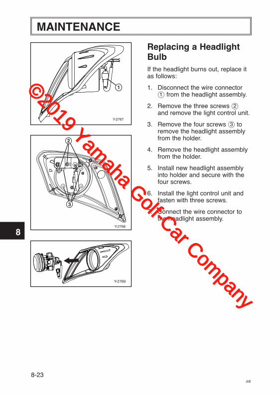
Replacing a HeadlightBulbIf the headlight burns out, replace itas follows:
1. Disconnect the wire connector1 from the headlight assembly.
2. Remove the three screws 2and remove the light control unit.
3. Remove the four screws 3 toremove the headlight assemblyfrom the holder.
4. Remove the headlight assemblyfrom the holder.
5. Install new headlight assemblyinto holder and secure with thefour screws.
6. Install the light control unit andfasten with three screws.
7. Connect the wire connector tothe headlight assembly.
Y-2769
Y-2767
1
Y-2768
2
3
©2019 Yamaha Golf-Car Com
pany
1
2
3
4
5
6
7
8
9
10
11
MAINTENANCE
J0E 8-24
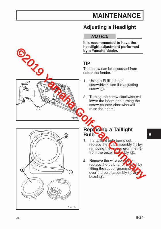
Adjusting a Headlight
It is recommended to have theheadlight adjustment performedby a Yamaha dealer.
TIPThe screw can be accessed fromunder the fender.
1. Using a Phillips head screwdriver, turn the adjustingscrew 1.
2. Turning the screw clockwise willlower the beam and turning thescrew counter-clockwise willraise the beam.
Replacing a TaillightBulb1. If a taillight bulb burns out,
replace the bulb assembly 1 byremoving the rubber grommet 2from the bezel assembly 3.
2. Remove the wire connector,replace the bulb, and reinstall byfitting the rubber grommet 2over the bulb assembly 1 andbezel 3.
NOTICE
Y-2771
13
2
Y-2770
1
©2019 Yamaha Golf-Car Com
pany
1
2
3
4
5
6
7
8
9
10
11
9-1
Perform the following preparationswhen storing your PTV for extendedperiods of time.
Yamaha Golf-Car Company doesnot approve the use of high-pressure washers to clean theproducts they manufacture. Doingso may damage the finish on thebody or result in doing otherdamage not covered by warranty.
TIPTurn main switch key to OFFposition, remove key and store key ina safe place.
CHASSIS PREPARATION1. Verify the tire pressure is set to 152
kPa, 1.5 kgf/cm2 (max 22 psi).
2. Clean exterior of the PTV andapply a rust inhibitor.
3. Cover the PTV with a breathablecover and store it in a dry, well-ventilated area.
NOTICE
BATTERY PREPARATION1. Recharge the batteries and
check the fluid levels at leastonce a month.
Do not allow cleaning solution toenter battery cells. Seriousbattery damage can result.
2. Clean the tops of the batterieswith a solution of baking sodaand water, as necessary, toremove corrosion.
NOTICE
STORAGE
J0E
©2019 Yamaha Golf-Car Com
pany
1
2
3
4
5
6
7
8
9
10
11
SPECIFICATIONS
10-1J0E
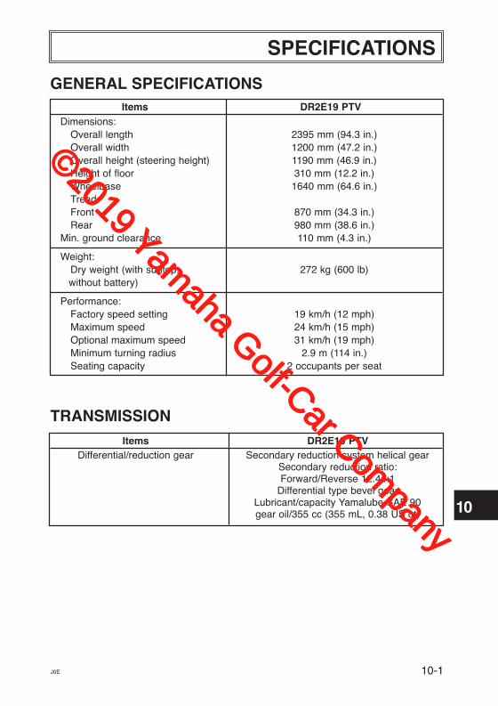
GENERAL SPECIFICATIONS Items DR2E19 PTV Dimensions: Overall length 2395 mm (94.3 in.) Overall width 1200 mm (47.2 in.) Overall height (steering height) 1190 mm (46.9 in.) Height of floor 310 mm (12.2 in.) Wheelbase 1640 mm (64.6 in.) Tread: Front 870 mm (34.3 in.) Rear 980 mm (38.6 in.) Min. ground clearance 110 mm (4.3 in.)
Weight: Dry weight (with suntop, 272 kg (600 lb)
without battery)
Performance: Factory speed setting 19 km/h (12 mph) Maximum speed 24 km/h (15 mph) Optional maximum speed 31 km/h (19 mph) Minimum turning radius 2.9 m (114 in.) Seating capacity 2 occupants per seat
TRANSMISSION Items DR2E19 PTV Differential/reduction gear Secondary reduction system helical gear Secondary reduction ratio: Forward/Reverse 12.44:1 Differential type bevel gear Lubricant/capacity Yamalube SAE 90 gear oil/355 cc (355 mL, 0.38 US qt)
©2019 Yamaha Golf-Car Com
pany
SPECIFICATIONS
1
2
3
4
5
6
7
8
9
10
11
10-2 J0E
BATTERIES
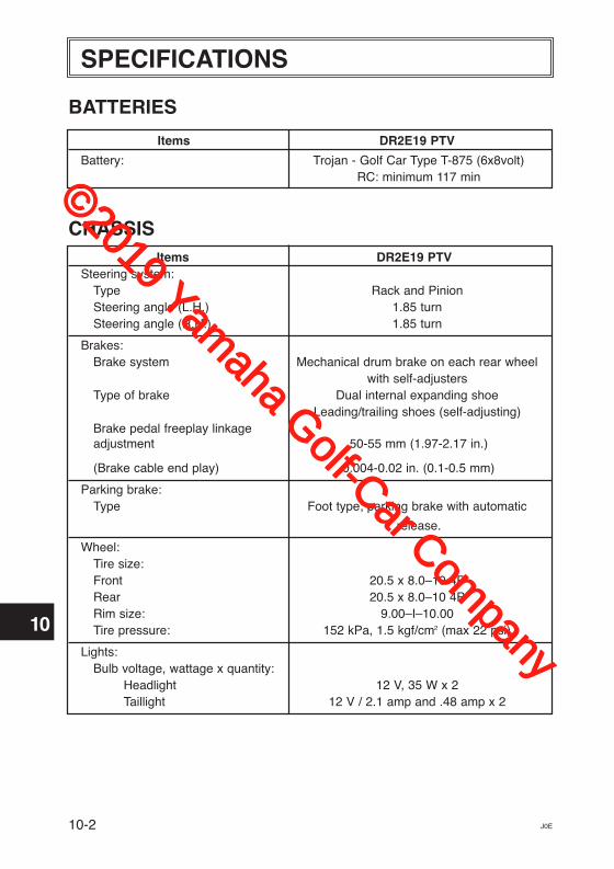
Items DR2E19 PTV
Battery: Trojan - Golf Car Type T-875 (6x8volt) RC: minimum 117 min
CHASSIS Items DR2E19 PTV Steering system: Type Rack and Pinion Steering angle (L.H.) 1.85 turn Steering angle (R.H.) 1.85 turn
Brakes: Brake system Mechanical drum brake on each rear wheel with self-adjusters Type of brake Dual internal expanding shoe Leading/trailing shoes (self-adjusting) Brake pedal freeplay linkage adjustment 50-55 mm (1.97-2.17 in.)
(Brake cable end play) 0.004-0.02 in. (0.1-0.5 mm)
Parking brake: Type Foot type; parking brake with automatic
release.
Wheel: Tire size: Front 20.5 x 8.0–10 4P Rear 20.5 x 8.0–10 4P Rim size: 9.00–I–10.00 Tire pressure: 152 kPa, 1.5 kgf/cm2 (max 22 psi)
Lights: Bulb voltage, wattage x quantity: Headlight 12 V, 35 W x 2 Taillight 12 V / 2.1 amp and .48 amp x 2
©2019 Yamaha Golf-Car Com
pany
1
2
3
4
5
6
7
8
9
10
11
10-3J0E
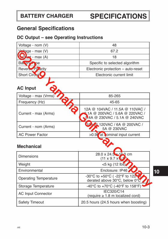
General Specifications
DC Output – see Operating Instructions
AC Input
Mechanical
Voltage - nom (V) 48
Voltage - max (V) 67.2
Current - max (A) 18
Battery Type Specific to selected algorithm
Reverse Polarity Electronic protection – auto-reset
Short Circuit Electronic current limit
Voltage - max (Vrms) 85-265
Frequency (Hz) 45-65
Current - max (Arms)12A @ 104VAC / 11.5A @ 110VAC /6.1A @ 200VAC / 5.6A @ 220VAC /5.4A @ 230VAC / 5.1A @ 240VAC
Current - nom (Arms) 10A @ 120VAC / 6A @ 200VAC /5A @ 230VAC
AC Power Factor >0.98 at nominal input current
Dimensions 28.0 x 24.5 x 14.0 cm(11 x 9.7 x 5.5")
Weight <5 kg (12 lbs)
Environmental Enclosure: IP46
Operating Temperature -30°C to +50°C ( -22°F to 122°F),derated above 30°C, below 0°C
Storage Temperature -40°C to +70°C (-40°F to 158°F)
AC Input Connector IEC320/C14 (require ≥ 1.8 m localized cord)
Safety Timeout 20.5 hours (24.5 hours when boosting)
SPECIFICATIONSBATTERY CHARGER
©2019 Yamaha Golf-Car Com
pany
1
2
3
4
5
6
7
8
9
10
11
10-4 J0E
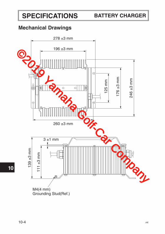
Mechanical Drawings
278 ±3 mm
196 ±3 mm
260 ±3 mm
176
±3
mm
125
mm
246
±3
mm
3 ±1 mm
M4(4 mm)Grounding Stud(Ref.)
139
±3
mm
111
±3
mm
SPECIFICATIONS BATTERY CHARGER
©2019 Yamaha Golf-Car Com
pany
11-1J0E
1
2
3
4
5
6
7
8
9
10
11
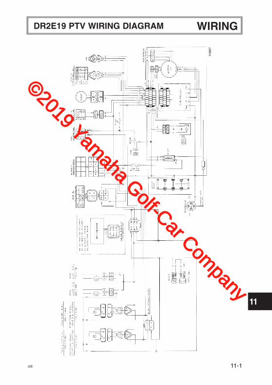
WIRINGDR2E19 PTV WIRING DIAGRAM
Y-28
27
©2019 Yamaha Golf-Car Com
pany
J0E
1
2
3
4
5
6
7
8
9
10
11
NOTES
©2019 Yamaha Golf-Car Com
pany

©2019 Yamaha Golf-Car Com
pany

PRINTED IN USA2018.12-0.3×2 CR
(E)
©2019 Yamaha Golf-Car Com
pany


![Tactical Vehicle Light Troop Transport Vehicle [LTTV]Based on the Mercedes UNIMOG chassis and running gear. Tactical Vehicle Light Troop Transport Vehicle [LTTV] With world-leading](https://img.pdfslide.net/doc/110x75/5eb4aebefeb74c7b775109e2/tactical-vehicle-light-troop-transport-vehicle-lttv-based-on-the-mercedes-unimog.jpg)