Embed Size (px)
Citation preview

Perspective Shadow Maps
Marc StammingerREVES/INRIA, Sophia-Antipolis, France
now at: Bauhaus-Universität, Weimar, Germany
George DrettakisREVES/INRIA, Sophia-Antipolis, France

Generate shadow
Hard shadows algorithms-Which are binary.
For example, shadow volumes ,depth buffer,ray tracing
Soft shadows algorithms-Also display the
penumbra area around the central umbra shadow.
For example, radiosity

Generate shadow
Ray Tracing Radiosity

Generate shadow
Kevin Weiler and Peter Atherton, Siggraph ‘1977– Hidden Surface Removal Using Polygon Area
Sorting
Franklin C., Siggraph ‘1977– Shadow Algorithms for Computer
Graphics

Traditional Shadow Maps
Williams, Siggraph ‘1978– render scene from light source– shadowing by depth comparison

Adaptive shadow maps
T.Lokovic E.Vearch , Siggraph ‘2000– Deep Shadow Maps
Randima F. Sebastian F. Kavita B., Siggraph ‘2001– Adaptive Shadow Maps– Replace the flat ahsdow map with an
adaptive,hierarchical representation.

Adaptive shadow maps
drawback:
By using multiple shadow maps,several rendering passes are required,and due to the more involved data structures,the methods no longer map to hardware.

Adaptive shadow maps

Introduction Method used to generate shadows: 1.clipping 2.shadow volumes These methods often suffer from robustness
problems due to the geometric computations required,and may also involve a significant rendering overhead.
Such algorithms are usually a preprocess,and are thus best suited to static scenes.

Introduction The paper by Lance Williams (Casting Curved
Shadows on Curved Surfaces) 1978 --“Shadow map“

Shadow Maps
The algorithm1.The depth values for the objects closest to
the source are stored to the depth map for each point.
2.As each point is generated into the obsevers view,it is transformed into the light source’s coordinate system and tested for visibility.
Result

shadow map aliasing
View frustum is for obsever
Light frustum is for light source

shadow map aliasing
NN

shadow map aliasing
N
α α
L/2
ds rs
1

shadow map aliasing
ds
rs
(L/2) * cosα
1
cos
1**
rs
cos*
1rsdsl
lds
cos
1**
rs
cos*
1rsdsl
lds
cos
1**
rs
cos*
1rsdsl
lds

shadow map aliasing
N
d
L/2β β
1
rs
cos
1**
ri
cos*
1ridl
ld

shadow map aliasing
cos
1**ridl
cos
1**rsdsl
cos
cos*
*
cos
1**
cos
1**
ri
rsdsdridrsds
shadow map aliasing
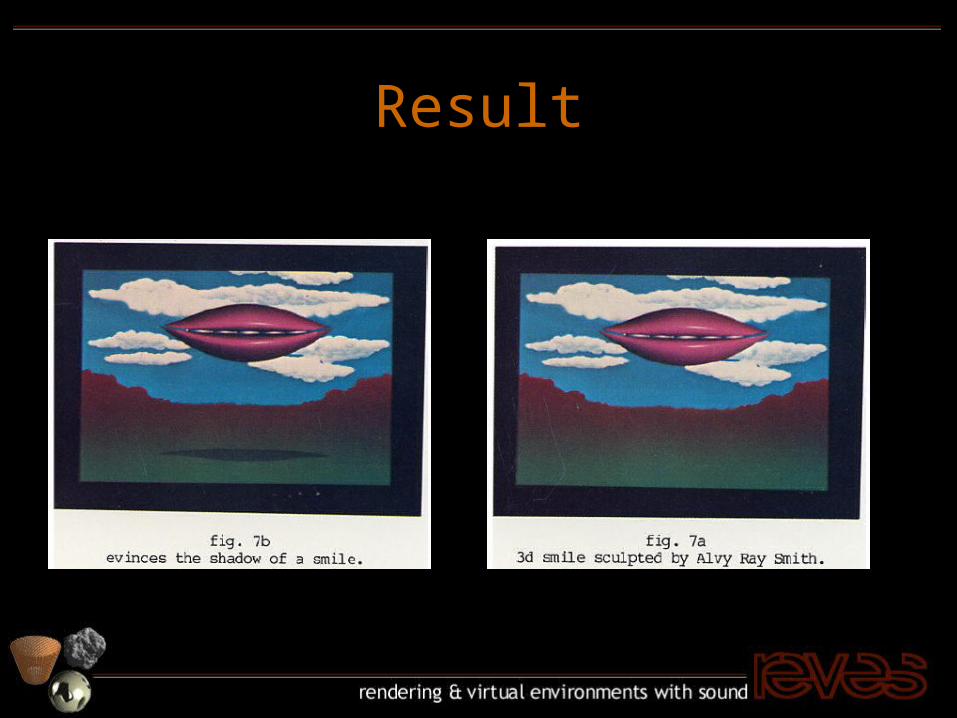
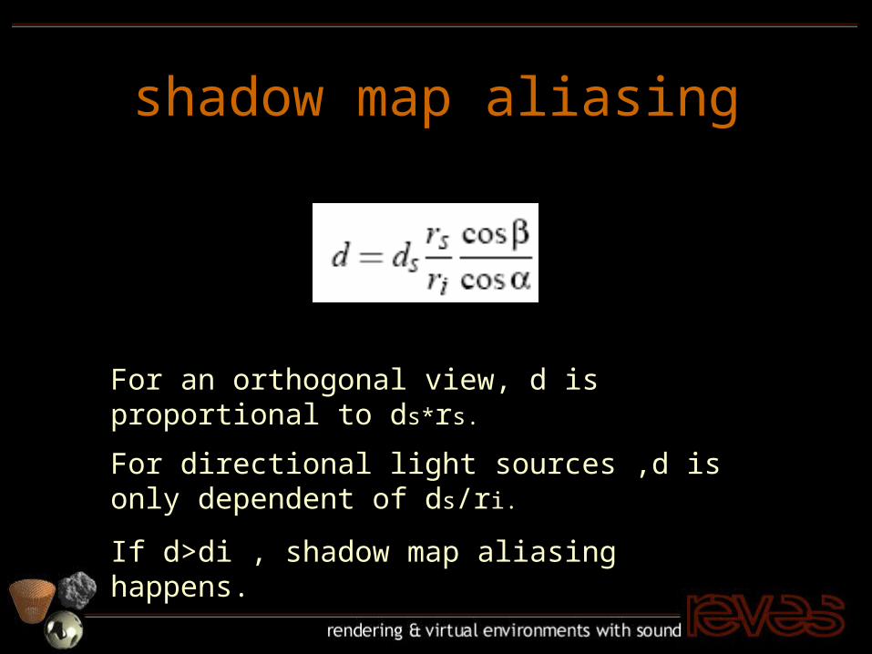
For an orthogonal view, d is proportional to ds*rs.
For directional light sources ,d is only dependent of ds/ri.
If d>di , shadow map aliasing happens.

shadow map aliasing
rs/ri is not close to a constant. cosβ /cosα become large. When the light rays are almost
parallel to a surface.
Situations

shadow map aliasing
prone to aliasingwhen zooming intoshadow boundaries
single shadow map pixel

shadow map aliasing
perspective aliasingparallel light
okay aliasedaliased okay

shadow map aliasing
perspective aliasing– smooth transition
alia
sed
o
vers
ampl
ed
shadow map aliasing
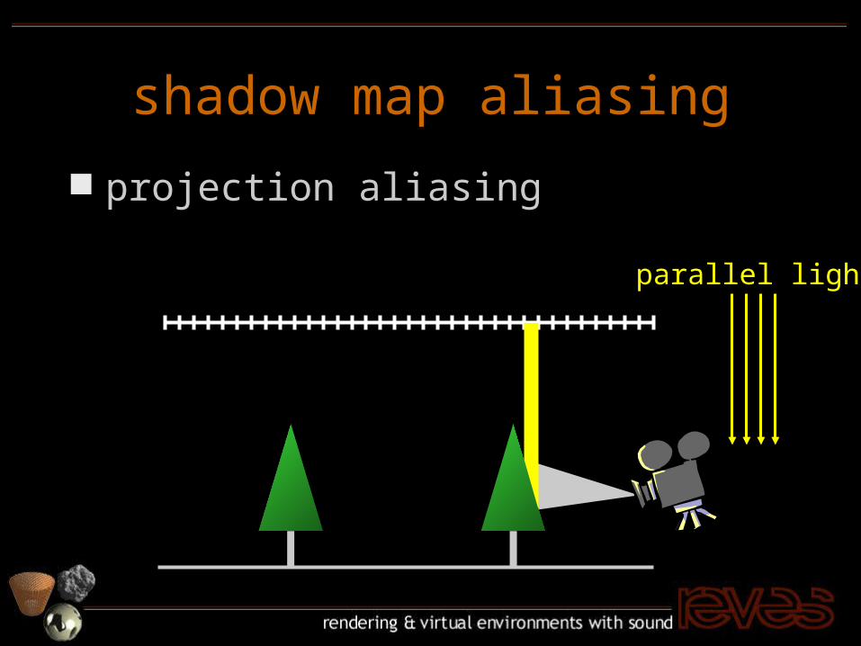
projection aliasing
parallel light

shadow map aliasing
projection aliasing– very local
alia
sed
o
vers
ampl
ed

Perspective shadow maps
Step
1. Mapping the scene to post-perspective space.
2. Generating a standard shadow map by rendering a view from the transformed light source to the unit cube.

perspective transformation
World space
Observer
f
n
(Camera distance)

perspective transformation
post
-pers
pect
ive
w
orl
d s
pace
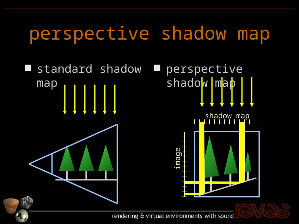
perspective shadow map
standard shadow map
perspective shadow map
shadow map
imag
e

perspective shadow map
standard shadow map
perspective shadow map
alia
sed
o
vers
ampl
ed

perspective shadow map
shadow map in post-perspective space
just another shadow map projection
reduces perspective aliasing regeneration per frame necessary

parallel light transformation
post
-pers
pect
ive
w
orl
d s
pace

parallel light transformation
1. Directional light sources can be considered as point lights at infinity plane.
2. The infinity plane is at: z=(f + n) / (f - n)
3. A directional light source from behind is mapped to a “inverted” point light source.
4. A directional light parallel to the image plane remains at infinity.

point light transformationpost
-pers
pect
ive
w
orl
d s
pace
front back

point light transformation
Point light on the plane through the view point which is perpendicular to the view direction ,become directional.

discussion
best case:– parallel light in
post-perspectivespace
– no new perspectivedistortion
post
-pers
pect
ive
w
orl
d s
pace

discussion
non-optimal case:– point light
close tofrustum
worst case:– becomes
uniformshadow map p
ost
-pers
pect
ive
w
orl
d s
pace

discussion
A common problem in shadow maps is the bias necessary to avoid self-occlusion or surface acne.
This problem is increased for perspective shadow maps ,because objects are scaled non-uniformly.
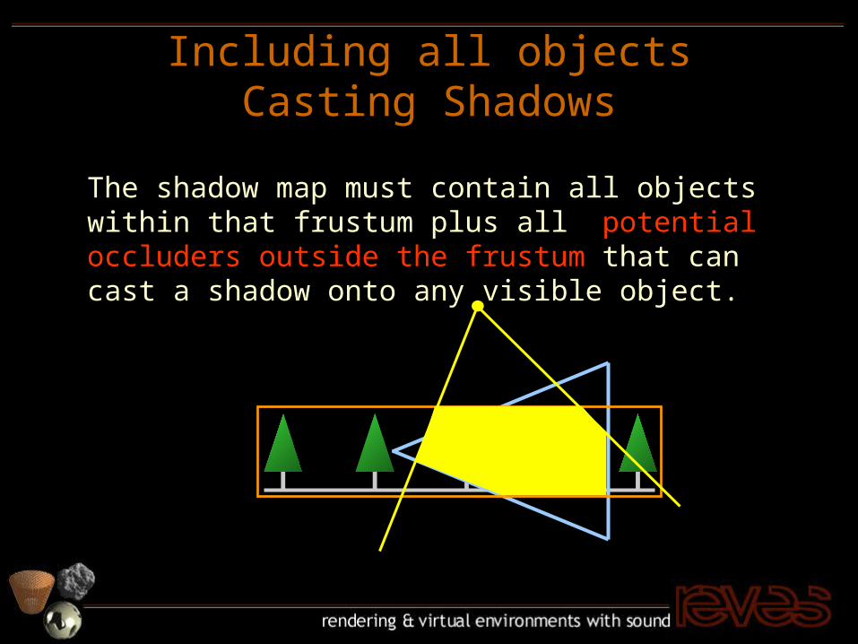
Including all objects Casting Shadows
The shadow map must contain all objects within that frustum plus all potential occluders outside the frustum that can cast a shadow onto any visible object.

shadow map window
geometric method to include all necessary objects

Including all objects Casting Shadows
In World Space

Including all objects Casting Shadows
In Post-perspective Space

Including all objects Casting Shadows
When a line intersects the camera plane, where the intersection point is mapped to infinity.
Moving the center of projection back, so that we are behind the furthermost point which can cast a shadow into the view frustum.
This camera point displacement is only for the shadow map generation , not for rendering the image.
Point Rendering
Point Rendering is particularly well suited for natural objects.
For the generation of uniform shadow maps point rendering loses most of its benefits.
Perspective Shadow Map fits nicely with the point rendering.

results

results
first implementation on an Xbox game developer kit
courtesy of Thatcher Ulrich

results

results

results
No shadows Uniform shadow map

results
Perspective shadow map

conclusion
perspective shadow maps– shadow map in post-perspective space– just another shadow map matrix– non-uniform shadow map resolution– needs recomputation per frame– minimal overhead for dynamic scenes

報告完畢