Embed Size (px)
Citation preview

CEA | 10 AVRIL 2012
PETAL :
a multi-PW beam
on LMJ facility
J.L. MIQUEL Experimental Validation & PETAL Projects Manager
CEA,DAM, F-91297 Arpajon, France
Retard = 50 fs Retard = 3 ps

2 J-L. Miquel CEA/DAM/DAN CP VEPL IZEST Livermore| 18 July 2013
The PETAL Project
PETAL is a part of the opening policy of CEA, and it will be dedicated to the scientific community
PETAL is supported by :
PETAL is a step toward :
The coupling of PETAL was previously planned with the LIL Facility
Transferring of PETAL and coupling with LMJ Quads was decided in 2010
Opportunity to study a wider field of physics and prepare efficiently HiPER

3 J-L. Miquel CEA/DAM/DAN CP VEPL IZEST Livermore| 18 July 2013
PETAL beamline
North
South
Focusing
Source
Compression stages (SS2)
Energy Bank
Implantation in LMJ building
PETAL
1st LMJ Quadruplets
© CEA 2010

4 J-L. Miquel CEA/DAM/DAN CP VEPL IZEST Livermore| 18 July 2013
PETAL goals
Energy : up to 3 kJ *
Wavelength : 1053 nm (526 nm option)
Pulse duration : from 0,5 to 10 ps
Intensity on target : ~ 1020 W/cm²
Power contrast : 10-7 at -7 ps
Energy contrast : 10-3
LMJ (1 beam)
Energy : up to 7.5 kJ (x 176 = 1,3 MJ)
Wavelength : 351 nm
Pulse duration : from 0,3 to 25 ns
Intensity on target : ~ 1015 W/cm²
* limited at the beginning to 1 kJ due to the damage threshold of the transport mirrors
PETAL characteristics versus LMJ

5 J-L. Miquel CEA/DAM/DAN CP VEPL IZEST Livermore| 18 July 2013
PETAL Project
Phase 2005 2006 2007 2008 2009 2010 2011 2012 2013 2014 2015
I- Key issues : Front End, Compression stage
II– Laser development : Front end & Amplifier section
III- Compression : Air
transport & Compression stages
IV- Focusing : Vacuum Transport & Focusing
V- Coupling to LMJ
LIL LMJ
6 J-L. Miquel CEA/DAM/DAN CP VEPL IZEST Livermore| 18 July 2013
Amplification kJ – UHI
PETAL = kJ-UHI « Robust »
• 3 kJ, sub-ps : CPA
• 3 kJ, robust : Nd:glass amplification
→ Amplifier section = LMJ type
Physical limitations
• Non-linear effects : filamentation
High stretching factor, vacuum, reflective optics
• Amplification : spectral narrowing
Pre-amplification with large Dl : OPCPA,
Power amplification : glass mixing
• Geometric and chromatic aberrations
Large size optics, thermal effect in amplifiers : deformable mirror
Chromatism corrector
Compressor adjustment
• Damage threshold
Large size optics, in vacuum, fs regime
Short pulse oscillator (100 fs)
Stretching (qq ns)
Amplification in the laser chain(qq kJ)
Compression (ps)
I
t t
I I
t
I
t
Filamentation
Damage Threshold

7 J-L. Miquel CEA/DAM/DAN CP VEPL IZEST Livermore| 18 July 2013
* E. Hugonnot et al., Appl. Opt. 45 (2006)
Front-End Architecture : OPCPA Technique
Pump
OPCPA amplifier Source
X 90 000
Femtosecond Laser 77.76 MHz - 1053 nm 3nJ - 100fs - 16nm
Pockels cells
Optical fiber (PM)
Collimator
Alimentation + Driver
Öffner stretcher Femtosecond
oscillator Pulse
selector
Driver
Signal 100 mJ - 1053 nm
4.5 ns - 8 nm Single shot
Fiber Oscillator monochromatic
Modulator A.O
Temporal pulse
shaping Collimator
Pockels Cells
Diode pumped amplifier
Fiber oscillator Regenerative amplifier
Pump 1.2J - 526nm - 4,5ns
monochromatic Single shot
Spatial beam shaping
LBO 25mm
BBO 15mm
Rod amplifier
Flash pumped amplifier
Laser Pump 14W CW (532nm)
Driver
KTP
collimator LBO 25mm
BBO 15mm
0
0,5
1
1025 1035 1045 1055 1065 1075
wavelength (nm)
Inte
nsit
y (
a.u
)
Input
Output

8 J-L. Miquel CEA/DAM/DAN CP VEPL IZEST Livermore| 18 July 2013
* E. Hugonnot et al., Appl. Opt. 45 (2006)
Pump Laser 14W
continuous 532nm
Femtosecond Laser
77.76 MHz – 1053 nm
3nJ - 100fs - 16nm
Pockels Cell
Optical Fiber(PM)
Collimator
Power supply + Driver
Öffner StretcherFemtosecond Oscillator
Pulse Selector
Driver
Signal Output
150mJ/1053nm/4,5ns/8nmsingle shot
Fibered oscillator
monochromatic
Acousto-optic
Modulator
Temporal
shaping
ModulatorCollimator
Pockels
Cell
Diode pumped
head
fibered SourceRegenerative Amplifier
Pump
1.2J/526nm/4,5ns/monochromaticSingle shot
KTPKTP
Active Beam
Shaper
Active Beam
Shaper
collimatorLBO
25mmBBO
15mm
Flash Pumped head
Power amplifier
Flash Pumped head
Power amplifier
100 mJ
Integrated Pre-amplifier Module (PAM)
Offner system
Pre-amplifier on table
Front End
output beam
(LIL)
Front end OPCPA : 100 mJ / 8 nm / 4.5 ns @ 1053 nm

9 J-L. Miquel CEA/DAM/DAN CP VEPL IZEST Livermore| 18 July 2013
LMJ → PETAL : 4 x 2 beams → 1 x 1 beam
LMJ architecture : 4 passes Amplifier slabs : Nd:phosphate glasses Beam size : 35 x 37 cm²
1,7 ns # 3 nm # 6,4 kJ
M1 deformable mirror
Chromatism Corrector*
© CEA 2011
PEPC
* C. Rouyer, Opt. Express 15, 2019-2032 (2007)
Amplifiers
Diffractive Fresnel Lens
© CEA 2007
Amplifier section : Architecture LIL/LMJ
Automatic alignment
10 J-L. Miquel CEA/DAM/DAN CP VEPL IZEST Livermore| 18 July 2013
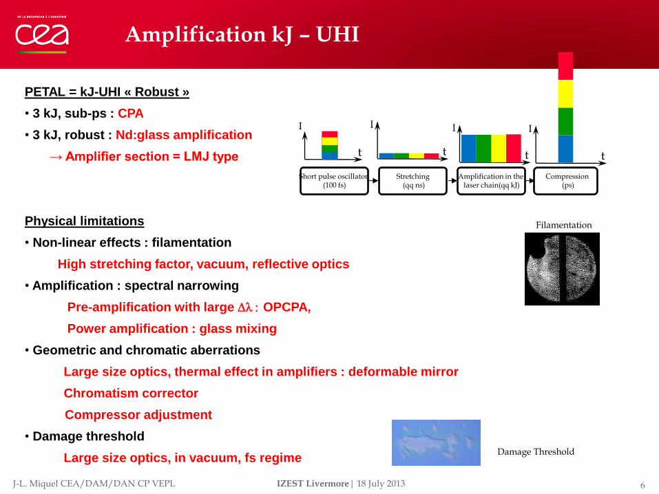
The Amplifier Section
Energy bank
Amplifier slab during the integration process
PETAL LMJ
LMJ Laser bay n°2
11 J-L. Miquel CEA/DAM/DAN CP VEPL IZEST Livermore| 18 July 2013
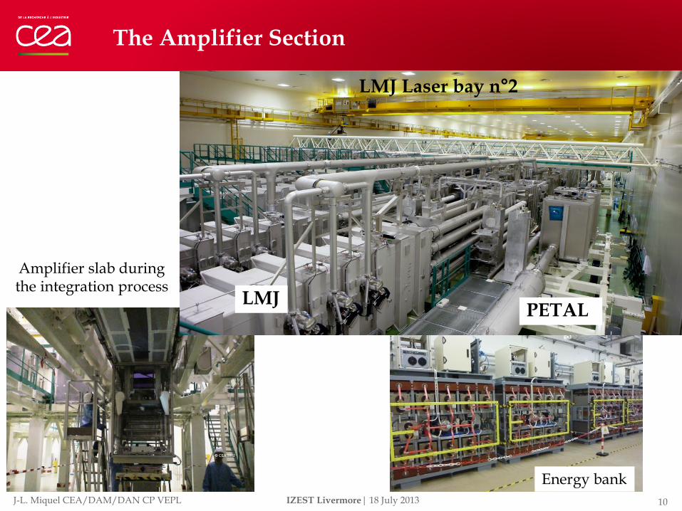
Transport, Compression, Focusing
Focusing
Vacuum Transport
Beam from Amplifier Section
Compression stages
Air Transport © CEA 2010
2 stages compression : 1st stage in air
Input : 6.4 kJ # 1.7 ns Output : 4.4 kJ # 350 ps
2nd stage in vacuum Output : 3.6 kJ # 0.5-10 ps

12 J-L. Miquel CEA/DAM/DAN CP VEPL IZEST Livermore| 18 July 2013
1,7 ns
6,4 kJ
500 fs
3,6 kJ
350 ps
4,4 kJ
Segmented mirror
Cylindrical mirror
Specific diagnostics
* N Blanchot, Opt. Express (2010)
4 J/cm² and 40 x 40 cm² beam → 400 x 1800 mm² gratings
→ 4 sub-aperture compressors with beam phasing
Grating developments
Compression Sub-aperture compression scheme*

13 J-L. Miquel CEA/DAM/DAN CP VEPL IZEST Livermore| 18 July 2013
Feedback of Phase 1 : Wavefront deformation due to grating modification under vacuum :
Pre-correction in air by segmented and cylindrical mirrors
Compression wavefront correction
4 compressors = Corrugated surface
Tilt of segments of segmented mirror
2 cylindrical mirrors or 1 toroidal mirror
Rx = Ry = ∞
RY RY RY RY
RX RX RX RX
RY RY RY RY
RX
Tr = Tr1 + Tr2
Front d’énergie
Front d’onde
Tr1 Tr2
Tr = 0
No impact on compressor performances

14 J-L. Miquel CEA/DAM/DAN CP VEPL IZEST Livermore| 18 July 2013
Segmented and toroidal Mirrors
Mirror segment : 1 translation 2 rotations
Mirrors support : 1 translation 2 rotations
Segment adjustment
axis Course sensibility
δZ +/- 10 µm 1 nm
θX +/- 40 µrad 0.05 µrad
θY +/- 40 µrad 0.05 µrad
PZT connected to capacitive sensor
Capacitive sensor
Segment
toroidal mirror

15 J-L. Miquel CEA/DAM/DAN CP VEPL IZEST Livermore| 18 July 2013
© CEA 2012 © CEA 2012
© CEA 2013 © CEA 2013
Compression box
Room for the 1st compression stage Room for the compression diagnostics
Compression stages

16 J-L. Miquel CEA/DAM/DAN CP VEPL IZEST Livermore| 18 July 2013
Transport and focusing of the compressed beam
Reservation for the 2w option
Pointing mirror
Alignment mirror Off-axis parabola
Focusing by off-axis parabola 7,8 m focal length, 90° deviation Multi-beam option Exploration for target : +/- 50 mm Focal spot ~ 50 µm
Box for the parabola
Vacuum transport

17 J-L. Miquel CEA/DAM/DAN CP VEPL IZEST Livermore| 18 July 2013
PETAL diagnostics
© CEA 2010
TDI
TEI
TDA
REA
TDC
DTF
SORF
RECO Légende : TDI : Table de Diagnostics d’Injection TDA : Table de Diagnostics d’Amplification TDC : Table de Diagnostics sortie Compresseur DTF : Diagnostic de Tache Focale
TEI : Tiroir Etalon d’Injection REA : Radiomètre Etalon d’Amplification RECO : Radiomètre Etalon de Compression
SORF : Système Optique de Réduction de Faisceau
Integrated Equipment
Equipment being integrated
Equipment being designed

18 J-L. Miquel CEA/DAM/DAN CP VEPL IZEST Livermore| 18 July 2013
Diagnostics SORF and TDA
SORF
Banc de réglage SORF sur la LIL
MDA VOSA
SORF
Salle E110
MT1
Bâti MDA
SORF MDA VOSA
CCD Energy
distribution
CCD Wave front
O.F. Temporal
O.F Spectrum
O.F Energy
Salle E110
Leaky mirror, beam reduction, diagnostics

19 J-L. Miquel CEA/DAM/DAN CP VEPL IZEST Livermore| 18 July 2013
Compressor Diagnostics TDC
Salle TDC (ISO8)
10 measurements for compressors alignment and compressed beam characterization :
Synchronization & Phase adjustment : spectral Interferometry
PETAL/LMJ synchronization
Characterization : Short time contrast Long time contrast Wavefront Energy
Compression : Far field Near field Spectral width Spectral phase
Salle ISO8 à SS2

20 J-L. Miquel CEA/DAM/DAN CP VEPL IZEST Livermore| 18 July 2013
• Absorption on precursor default (scratch, SSD, inclusion, structural default)
• Plasma, pressure, shock wave, … → damage
•Complex, multi-physic problem
• Multi-photonic absorption, tunnel effect ionization , relaxation, …
• Ne > NCr (1020 à 1022 e-/cm3)
→ Dielectric breakdown = damage
Silice 351nm, 3ns, 30 J/cm²
Norton SPIE 6403 (2007)
ns sub-ps
The damage threshold problem
Silice 1053nm, 400 fs, 3 J/cm²
Sub-ps and ns damages

21 J-L. Miquel CEA/DAM/DAN CP VEPL IZEST Livermore| 18 July 2013
Great efforts have been made on gratings*
Modélisation des
structures
Tests sur échantillons
100 200 300 400 500
1200
1400
1600
1800
2000
2200
2400
2600
HfO2
SiO2
HfO2
SiO2
06-0676
0
0.1875
0.3750
0.5625
0.7500
0.9375
1.125
1.313
1.500
1.688
1.875
2.063
2.250
2.438
2.625
2.813
3.000
X Axis
Y A
xis
Métrologie LMO, physique
de l’endommagement fs
Fabrication industrielle
pleine taille
- The effect of E field has been demonstrated (2006-2011 - 7 publications)
-PETAL gratings have been optimized :
threshold > 4J/cm²
- Work in progress with new structures
(2 patents)
* J. Néauport, Opt. Express 15 (2007)

22 J-L. Miquel CEA/DAM/DAN CP VEPL IZEST Livermore| 18 July 2013
But mirrors cannot sustain more than 2-2.4 J/cm² (4 J/cm² specified) : new technologies are needed
0
0,1
0,2
0,3
0,4
0,5
0,6
0,7
0,8
0,9
1
1,5 1,7 1,9 2,1 2,3 2,5 2,7 2,9 3,1 3,3 3,5
Pro
babili
té
Fluence moyenne (J/cm²)
Probabilité d'endommagementEchantillon DKTOB54 - polaristion S et P - 45°
fluence calculée avec 90% de l'énergie
Pola P
Pola S
Maximum energy available :
Test on Mirror : 2.4 J/cm² @ 500 fs Correspond to Ebeam = 3.4 kJ Beam modulation => Emax~ 1 kJ
Perhaps more : spectral smoothing
Study of damages morphology :
Several damage processes can be observed depending on material properties and/or irradiation conditions :
Thermal effects Mechanical effects Ripples, surface plasmons Plasma burn
Monochromatic Broad spectrum (16 nm)

23 J-L. Miquel CEA/DAM/DAN CP VEPL IZEST Livermore| 18 July 2013
Ways of improvment
Materials :
Test of high index materials (other than HfO2)
Test of mixtures
…
Coating processes :
e-beam + IAD
IBS
Impact of process on wave front
Design of layers :
Multi-materials coating (nb>2)
Adjustment of layers thickness
Combination multi-materials + layers thickness
…
| PAGE 23 11.7.2013
Effect of coating process parameters (IAD)
Use of mixtures (IBS)

24 J-L. Miquel CEA/DAM/DAN CP VEPL IZEST Livermore| 18 July 2013
Dammage threshold of materials and mixtures
Case of simple materials for laser coatings
500 fs, 1on1, 1030 nm
Low index
High index
Case of mixtures

25 J-L. Miquel CEA/DAM/DAN CP VEPL IZEST Livermore| 18 July 2013
Physics with PETAL – 1 : “Standard” HED Physics
Generation of intense electron, ion and X-ray beams
Electrons up to 150 MeV (Temperature 7-10 MeV)
Protons up to 120 MeV (Temperature 6-14 MeV)
Study of their propagation in Warm Dense Matter
Stopping power
Extreme WDM states by short-pulse
Isochoric heating
Laboratory Astrophysics Experiments
Opacity, hydrodynamics similarity, …
Fast ignition experiments

26 J-L. Miquel CEA/DAM/DAN CP VEPL IZEST Livermore| 18 July 2013
Physics with PETAL – 2 : Extreme Physics
Acceleration and High Energy Physics Electron acceleration to 100 GeV- 1 TeV
Channel-guided acceleration by laser wakefield in low density plasma
Extreme power laser Cascaded Compression Conversion (C3) scheme, up to EW :
Coupling of CPA, OPCPA & Backward Raman (or Brillouin) Amplification
CPA
OPCPA BRA
A. Puckov -> K. Nakajima talk
-> T. Kuehl talk

27 J-L. Miquel CEA/DAM/DAN CP VEPL IZEST Livermore| 18 July 2013
Ali.1w
J F M A M J A S O N D J
2012 J F M A M J A S O N D J
2013 J F M A M J A S O N D J
2014 J A S O N D J
2011
Shots 1w
Shots 3w
Command-Control Tests
Assembly Alignt 1B AS
Assembly
Alignt 4B AS
Ali. 4B TCF
Ali. CC
Schedule for LMJ first experiments
M1
PAM
PEPC Polarisers
SCF
Amplifier
First Experiments

28 J-L. Miquel CEA/DAM/DAN CP VEPL IZEST Livermore| 18 July 2013
1st LMJ QUAD PETAL Equatorial plan
Schedule for PETAL on LMJ
© CEA 2011
80 to 90°
Experiments with PETAL will begin in 2016
LMJ/PETAL, as LIL, will be open to the scientific community
2014 2015 2016 2017 2018
Commis-sioning
Full access (call for proposals beginning in 2015)
First experiments (Restricted access)
LMJ increasing capabilities
(beams number, energy, shots number, plasma diagnostics, targets, …)
First LMJ experiments LMJ
PETAL
Last alignment
Commissioning
Align

Thank you for your attention
Direction des applications militaires
Direction des armes nucléaires
Commissariat à l’énergie atomique et aux énergies alternatives
Centre DAM Île de France – Bruyères-le-Châtel| 91297 Arpajon Cedex
T. +33 - (0)1 69 26 62 16 | F. +33 - (0)1 69 26 70 03
Etablissement public à caractère industriel et commercial | RCS Paris B 775 685 019

30 J-L. Miquel CEA/DAM/DAN CP VEPL IZEST Livermore| 18 July 2013
PETAL Plasma Diagnostics
PETAL+ project :
Funded by ANR and managed by the University of Bordeaux Two diagnostics + inserters Availability : 2016
Charged particles diagnostic :
Proton spectroscopy & Imaging (proton-radiography) 100 keV-200 MeV
Electron spectroscopy 100 keV – 150 MeV
Hard X-ray spectrometer
7 – 100 keV (2 transmission crystals) .
Shielding : high energy X-ray and particles (magnets)