Embed Size (px)
Citation preview
395
Int. J. Mech. Eng. & Rob. Res. 2014 B Seshagiri Rao and D Gopi Chandu, 2014
ISSN 2278 – 0149 www.ijmerr.com
Vol. 3, No. 4, October, 2014
© 2014 IJMERR. All Rights Reserved
Research Paper
PETROL ENGINE EXHAUST VALVE DESIGN,ANALYSIS AND MANUFACTURING PROCESSES
B Seshagiri Rao1* and D Gopi Chandu1
*Corresponding Author: B Seshagiri Rao � [email protected]
The aim of this paper is to design an exhaust valve for a four wheeler petrol engine usingtheoretical calculations. Manufacturing process that is 2D drawings is drafted from the calculationsand 3D model and transient thermal analysis is to be done on the exhaust valve when valve isopen and closed. Analysis is done in ANSYS. Analysis will be conduct when the study statecondition is attained. Study state condition is attained at 5000 cycles at the time of when valveis closed is 127.651 sec valve is opened 127.659 sec.The material used for exhaust valve isEN52 steel. We are doing material optimization bydoing analysis on both materials EN52 andEN59.Static Modal analysis the exhaust valve to determine mode shapes of the valve for numberof modes.
Keywords: Petrol Engine, Exhaust Valve Design, Analysis, Manufacturing Processes
1 Mechanical Engineering Department, Mother Teresa Institute of Science and Technology, Khammam, Telangana-507 303.
INTRODUCTION
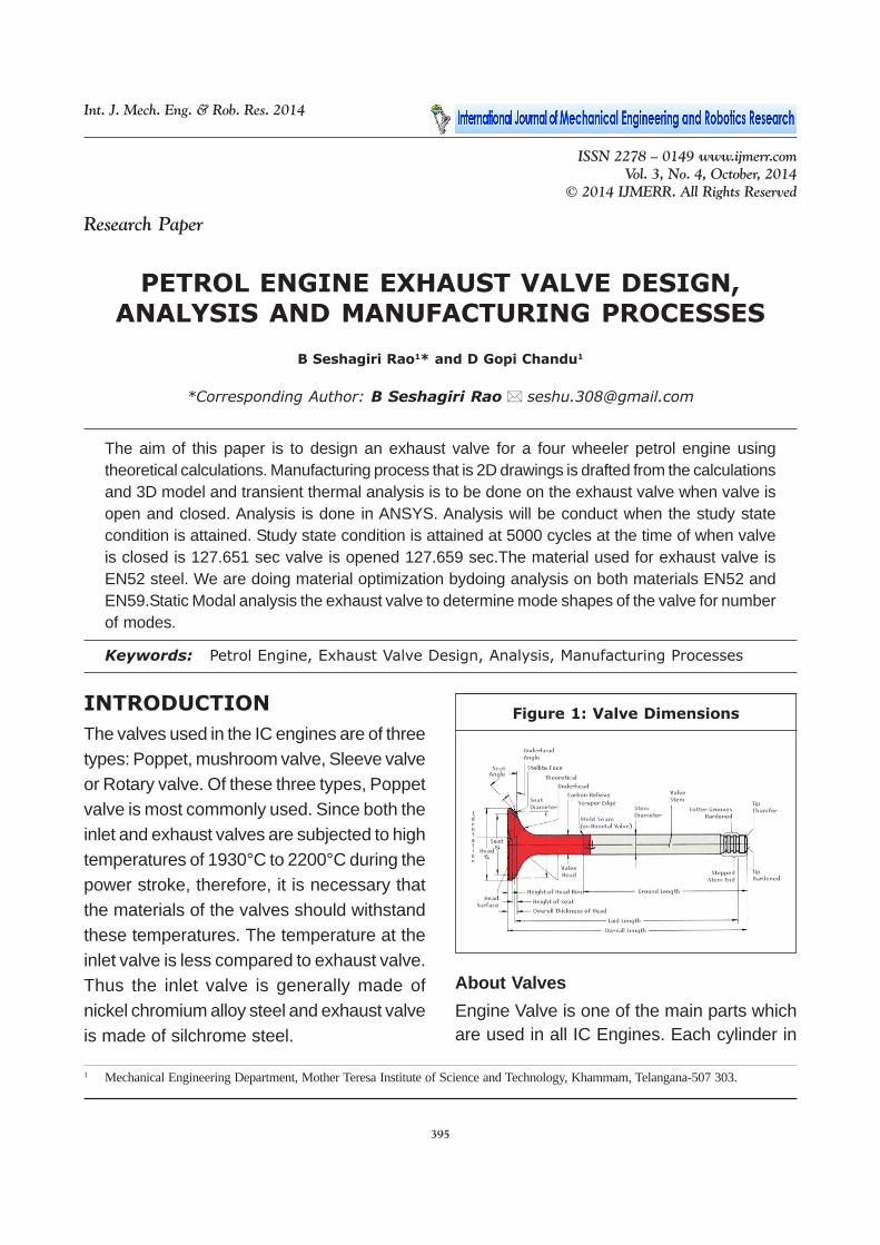
The valves used in the IC engines are of threetypes: Poppet, mushroom valve, Sleeve valveor Rotary valve. Of these three types, Poppetvalve is most commonly used. Since both theinlet and exhaust valves are subjected to hightemperatures of 1930°C to 2200°C during thepower stroke, therefore, it is necessary thatthe materials of the valves should withstandthese temperatures. The temperature at theinlet valve is less compared to exhaust valve.Thus the inlet valve is generally made ofnickel chromium alloy steel and exhaust valveis made of silchrome steel.
About Valves
Engine Valve is one of the main parts whichare used in all IC Engines. Each cylinder in
Figure 1: Valve Dimensions
396
Int. J. Mech. Eng. & Rob. Res. 2014 B Seshagiri Rao and D Gopi Chandu, 2014
the engine has one inlet and one exhaustvalve. Now a days engine are designed withmulti valves viz., two inlet and one exhaustor Two inlet and Two exhaust valves whichprevents air pollution and improves engineefficiency.
Function of Inlet Valve
The inlet which operates by the action ofTappet movement, allows air and fuel mixtureinto the cylinder.
Function of Exhaust Valve
The exhaust valve allows burnt gases toescape from the cylinder to atmosphere.
Valve Efficiency
Depends on the following characteristics likeHardness, Face roundness and slidingproperties capable to withstand hightemperature etc.
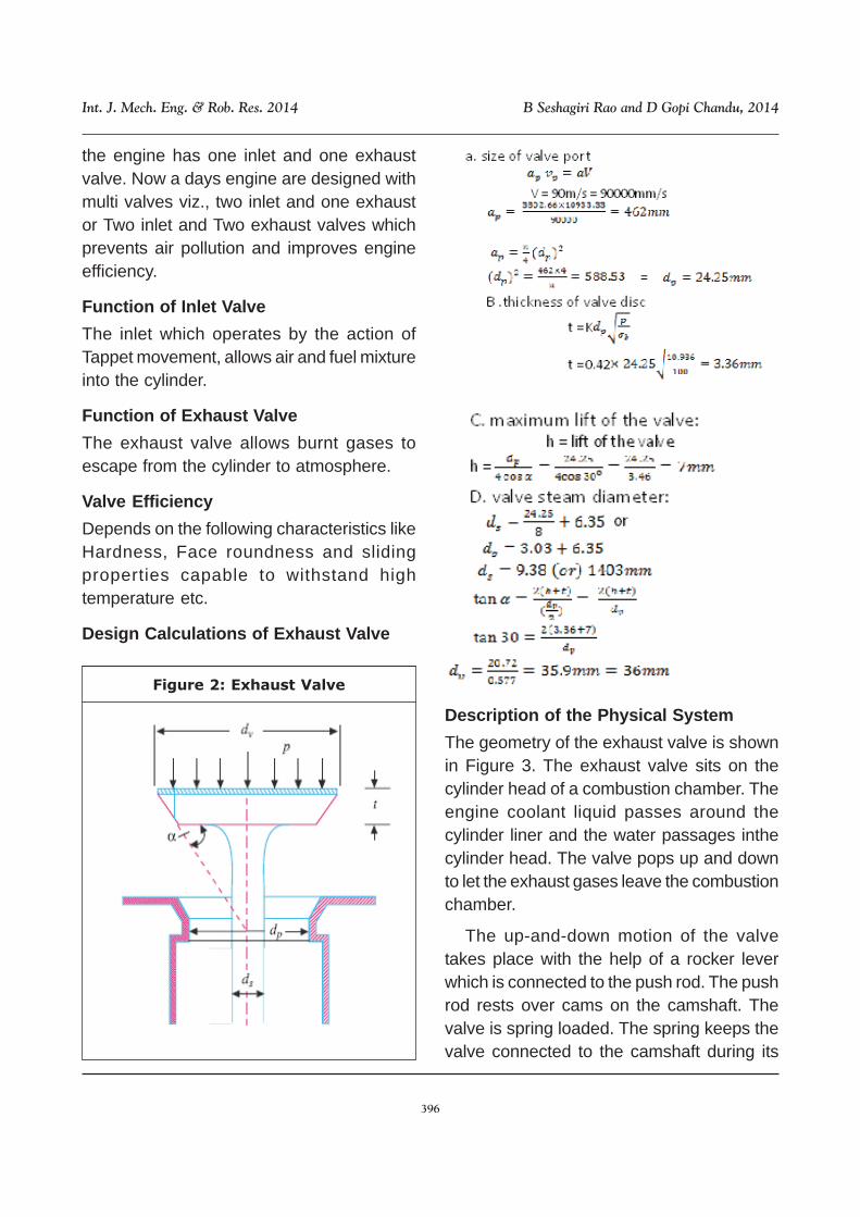
Design Calculations of Exhaust Valve
Figure 2: Exhaust Valve
Description of the Physical System
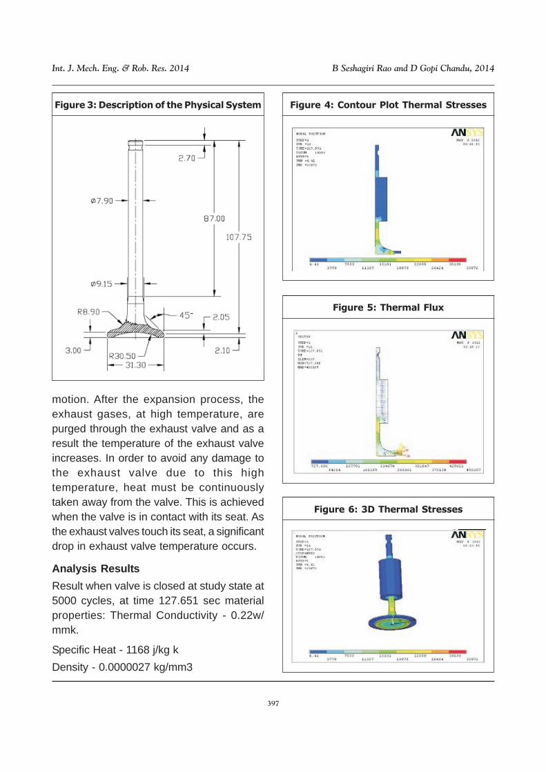
The geometry of the exhaust valve is shownin Figure 3. The exhaust valve sits on thecylinder head of a combustion chamber. Theengine coolant liquid passes around thecylinder liner and the water passages inthecylinder head. The valve pops up and downto let the exhaust gases leave the combustionchamber.
The up-and-down motion of the valvetakes place with the help of a rocker leverwhich is connected to the push rod. The pushrod rests over cams on the camshaft. Thevalve is spring loaded. The spring keeps thevalve connected to the camshaft during its
397
Int. J. Mech. Eng. & Rob. Res. 2014 B Seshagiri Rao and D Gopi Chandu, 2014
Figure 3: Description of the Physical System
motion. After the expansion process, theexhaust gases, at high temperature, arepurged through the exhaust valve and as aresult the temperature of the exhaust valveincreases. In order to avoid any damage tothe exhaust valve due to this hightemperature, heat must be continuouslytaken away from the valve. This is achievedwhen the valve is in contact with its seat. Asthe exhaust valves touch its seat, a significantdrop in exhaust valve temperature occurs.
Analysis Results
Result when valve is closed at study state at5000 cycles, at time 127.651 sec materialproperties: Thermal Conductivity - 0.22w/mmk.
Specific Heat - 1168 j/kg k
Density - 0.0000027 kg/mm3
Figure 4: Contour Plot Thermal Stresses
Figure 5: Thermal Flux
Figure 6: 3D Thermal Stresses
398
Int. J. Mech. Eng. & Rob. Res. 2014 B Seshagiri Rao and D Gopi Chandu, 2014
Figure 8: Contour Plot Thermal Stresses
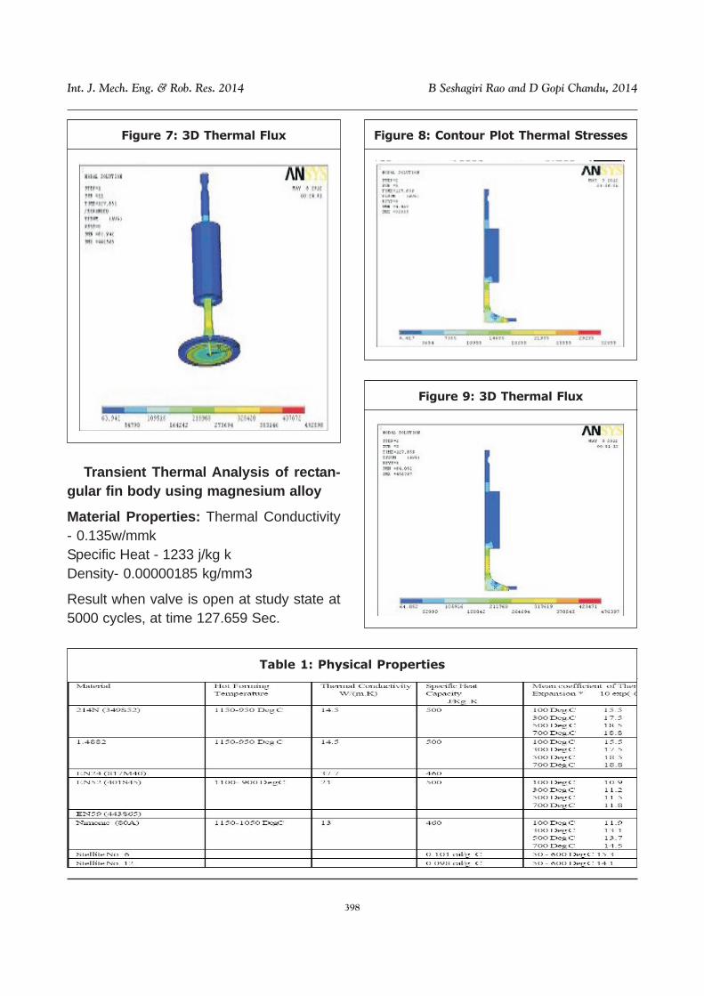
Transient Thermal Analysis of rectan-gular fin body using magnesium alloy
Material Properties: Thermal Conductivity- 0.135w/mmkSpecific Heat - 1233 j/kg kDensity- 0.00000185 kg/mm3
Result when valve is open at study state at5000 cycles, at time 127.659 Sec.
Figure 7: 3D Thermal Flux
Figure 9: 3D Thermal Flux
Table 1: Physical Properties
399
Int. J. Mech. Eng. & Rob. Res. 2014 B Seshagiri Rao and D Gopi Chandu, 2014
Specific Heat - is the ratio of heat requiredto raise the temperature of a certain weightof material by 1 Deg C to that required toraise the temperature of the same weight ofwater by 1 Deg C, Coefficients of ThermalExpansion for Valve Guide Material (between0 and 200 Deg C, in 10 exp(-6).K(-1)). CastIron 11, Phosphor Bronze 18, AluminumBronze 18
*Note - To find the expansion at 300 DegC of a valve with a stem diameter of 0.275”in 214N material. (Assuming the stemdiameter was measured at 20 Deg. C), thetemperature difference is (300 Deg C - 20Deg C) = 280 Deg C.Stem diameter xtemperature difference x coefficient ofthermal expansion = Expansion of Valve
Ie: 0.275 x 280 x 0.0000175 = 0.0013
6.0 PTA Deposition Plasma TransferredArc Process ( PTA Process ) is used to fusea metallic coating to a substrate in order toimprove its resistance against wear and/orcorrosion. This technique is called hardfacing,wear surfacing, or more commonly wearfacing. During the process, metal powder isfed into a molten weld puddle (fusion bath)generated by the plasma arc at hightemperature (up to 20,000 °C). All weldingparameters, including powder feed, powerinput, plasma gas and shielding gas, as wellas torch and workpiece movement areautomatized and computer controlled inPLASMA TEAM equipment. PTA hardfacingis a true welding process, with a metallic bondbetween the substrate and deposit. Depositthickness can range from 0.6 to 6.0 mm, widthfrom 3 to 10 mm when using a single pass;multipass welding reaches deposit
thicknessup 20 mm and width over 30mm.The core of PTA process is PLASMA.The plasma (a gas sufficiently ionized to beelectrically conductive) can be viewed as thenatural state of matter (the so called fourthstate of matter), with the other states existingonly as variants to the normal. Plasma stateconstitutes more than 99.9% of all matter inthe universe. Thermal plasma describes agas which is at least 1% ionized, with atemperature greater than 13,000 °C, and isa good electrical conductor.
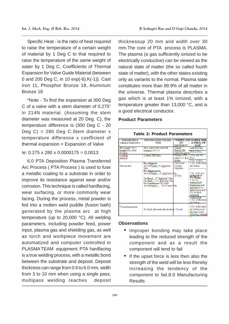
Product Parameters
Observations
• Improper bonding may take placeleading to the reduced strength of thecomponent and as a result thecomponent will tend to fail
• If the upset force is less then also thestrength of the weld will be less therebyincreasing the tendency of thecomponent to fail.8.0 ManufacturingResults
Table 2: Product Parameters
400
Int. J. Mech. Eng. & Rob. Res. 2014 B Seshagiri Rao and D Gopi Chandu, 2014
Valve Process Flow with Head to PinFriction Welding
1. One halve of the bar is upsetted andthen forged.
2. Now the forged head is welded toanother bar by friction welding.
3. Deburring is done to remove the flashgenerated in friction welding
4. The valves obtained are straightenedand given as input to rough centrelessGrinding operation..
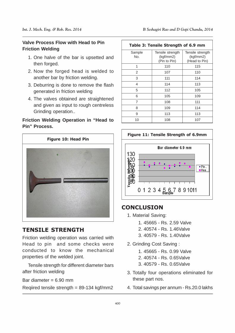
Friction Welding Operation in “Head toPin” Process.
Figure 10: Head Pin
TENSILE STRENGTH
Friction welding operation was carried withHead to pin and some checks wereconducted to know the mechanicalproperties of the welded joint.
Tensile strength for different diameter barsafter friction welding
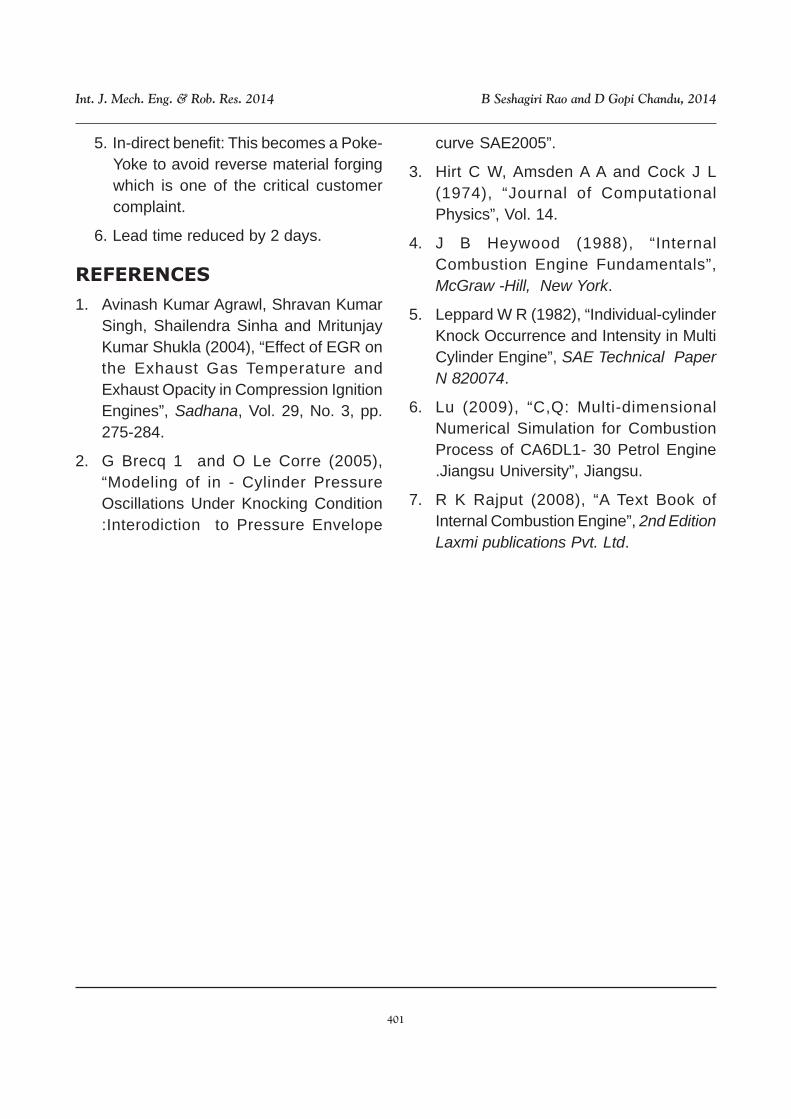
Bar diameter = 6.90 mm
Reqiired tensile strength = 89-134 kgf/mm2
Table 3: Tensile Strength of 6.9 mm
SampleNo.
1
2
3
4
5
6
7
8
9
10
Tensile strength(kgf/mm2)(Pin to Pin)
110
107
111
114
112
105
108
109
113
108
Tensile strength(kgf/mm2)
(Head to Pin)
115
110
114
113
105
109
111
114
113
107
Figure 11: Tensile Strength of 6.9mm
CONCLUSION
1. Material Saving:
1. 45665 - Rs. 2.59 Valve2. 40574 - Rs. 1.46Valve3. 40579 - Rs. 1.40Valve
2. Grinding Cost Saving :
1. 45665 - Rs. 0.99 Valve2. 40574 - Rs. 0.65Valve3. 40579 - Rs. 0.65Valve
3. Totally four operations eliminated forthese part nos.
4. Total savings per annum - Rs.20.0 lakhs
401
Int. J. Mech. Eng. & Rob. Res. 2014 B Seshagiri Rao and D Gopi Chandu, 2014
5. In-direct benefit: This becomes a Poke-Yoke to avoid reverse material forgingwhich is one of the critical customercomplaint.
6. Lead time reduced by 2 days.
REFERENCES
1. Avinash Kumar Agrawl, Shravan KumarSingh, Shailendra Sinha and MritunjayKumar Shukla (2004), “Effect of EGR onthe Exhaust Gas Temperature andExhaust Opacity in Compression IgnitionEngines”, Sadhana, Vol. 29, No. 3, pp.275-284.
2. G Brecq 1 and O Le Corre (2005),“Modeling of in - Cylinder PressureOscillations Under Knocking Condition:Interodiction to Pressure Envelope
curve SAE2005”.
3. Hirt C W, Amsden A A and Cock J L(1974), “Journal of ComputationalPhysics”, Vol. 14.
4. J B Heywood (1988), “InternalCombustion Engine Fundamentals”,McGraw -Hill, New York.
5. Leppard W R (1982), “Individual-cylinderKnock Occurrence and Intensity in MultiCylinder Engine”, SAE Technical PaperN 820074.
6. Lu (2009), “C,Q: Multi-dimensionalNumerical Simulation for CombustionProcess of CA6DL1- 30 Petrol Engine.Jiangsu University”, Jiangsu.
7. R K Rajput (2008), “A Text Book ofInternal Combustion Engine”, 2nd EditionLaxmi publications Pvt. Ltd.