Embed Size (px)
Citation preview
PETROLEUM AND NATURAL GAS REGULATORY BOARD
NOTIFICATION
New Delhi, the ________
G.S.R.____. In exercise of the powers conferred by section 61 of the Petroleum and Natural Gas Regulatory Act, 2006 (19 of 2006), the Petroleum and Natural Gas Regulatory Board hereby makes the following Regulations, namely:-
1. Short title and commencement.
(1) These Regulations may be called ―The Petroleum and Natural Gas Regulatory Board
(Technical Standards and Specifications including Safety Standards for Retail Outlets
dispensing Petroleum, Auto LPG and CNG) Regulations, 2016‖.
(2) They shall come into force on the date of their publication in the Official Gazette.
2. Definitions.
(1) In these regulations, unless the context otherwise requires,
a. ―Act‖ means the Petroleum and Natural Gas Regulatory Board Act, 2006;
b. ―Board‖ means the Petroleum and Natural Gas Regulatory Board established under sub-
section (1) of section 3 of the Act;
c. ―Authorised Person ―means a person trained and assigned to carry out a specific job by the
owner or marketing company. d. “Competent Person‖ mean a person recognised by the concerned Statutory Authority for the
purpose in respect of which the competency is required. e. ―Flame-proof ― means a type of protection in which an enclosure can withstand the pressure
developed during an internal explosion of an explosive mixture and that prevents the transmission of the explosion to the explosive atmosphere surrounding the enclosure and that operates at such an external temperature that a surrounding explosive gas or vapor will not be ignited there. This type of protection is referred to as "Ex d".
f. ―Intrinsically Safe‖ means a type of protection in which the electrical equipment under normal
or abnormal conditions is incapable of releasing sufficient electrical or thermal energy to cause ignition of a specific hazardous atmospheric mixture in its most easily ignitable concentrations. This type of protection is referred to as "Ex i".
g. ―Increased Safety‖ means a type of protection in which various measures are applied to reduce the
probability of excessive temperatures and the occurrence of arcs or sparks in the interior and on the external parts of electrical apparatus that do not produce them in normal service. Increased safety may be used with flame-proof type of protection. This type of protection is referred to as "Ex e".
h. ―Type n‖ means a type of protection applied to electrical equipment such that in normal operation it is not capable of igniting a surrounding explosive atmosphere. This type of protection is referred to as "Ex n".
i. ―Hazardous Area‖ means the locations classified according to its Zone System which
defines the probability of the hazardous material, gas or dust, being present in sufficient quantities to produce explosive or ignitable mixtures as below :

i. ―Zone 0‖ means ignitable concentrations of flammable gases or vapours which are present
continuously or for long periods of time. ii. ―Zone 1‖ means ignitable concentrations of flammable gases or vapours which are likely to
occur under normal operating conditions.
iii. ―Zone 2‖ means ignitable concentrations of flammable gases or vapours which are not likely to occur under normal operating conditions and do so only for a short period of time.
j. ―Approved Type‖ means any equipment which has specific approval for use under specified
conditions by competent authority or authorized person as the case may be.
k. ―Capacity‖ means the maximum volume of water that can be stored in a vessel/container at 15
oC at atmospheric pressure.
l. ―Shall‖ Indicates mandatory requirement.
m. ―Should‖ Indicates recommendation or that which is advised but not mandatory.
(2) Words and expressions used and not defined in these regulations, but defined in the Act or in
the rules or regulations made there under, shall have the meanings respectively assigned to
them in the Act or in the rules or regulations, as the case may be.
3. Application.
Definitions, layout, design, operating procedures, maintenance, inspection, safety equipment, competence assurance, emergency management plan, customer safety and awareness shall be in accordance with the requirements of these regulations.
4. Scope.
(1) Requirements of these regulations shall apply to all existing and new Retail Outlets dispensing
Petroleum products such as MS, HSD, Auto LPG, LNG, CNG and their variants.
(2) These regulations covers the minimum requirements for engineering and safety considerations in
layout, design, operating procedures, maintenance, inspection, safety equipment, electrical
power distribution system, automation, competence assurance, emergency management plan,
customer safety and awareness at Retail Outlets dispensing Petroleum products such as MS,
HSD, Auto LPG, LNG, CNG and their variants.
5. Objective.
These standards are intended to ensure uniform application of design principles in layout, material and equipment selection, construction etc., as mentioned in ―Application‖ above for safe operation at the Retail Outlets dispensing Petroleum products such as MS, HSD, Auto LPG, LNG, CNG and their variants.
6. The standard.
(1) Technical standards and specifications including safety standards (hereinafter referred to as
standards) for Petroleum Retail Outlets are as specified in Schedule-I which cover layout,
design, operating procedures, maintenance, inspection, safety equipment, electrical power
distribution system, automation, competence assurance, emergency management plan,
customer safety and awareness.
(2) Technical standards and specifications including safety standards (hereinafter referred to as
standards) for Retail Outlets dispensing Auto LPG are specified in Schedule – 2 which cover
layout, design, operating procedures, maintenance, inspection, safety equipment, electrical
power distribution system, automation, competence assurance, emergency management plan,
customer safety and awareness.
(3) Technical standards and specifications including safety standards (hereinafter referred to as
standards) for Retail Outlets dispensing CNG are specified in Schedule – 3 which cover layout,
design, operating procedures, maintenance, inspection, safety equipment, electrical power
distribution system, automation, competence assurance, emergency management plan,
customer safety and awareness.
7. Compliance to these regulations
(1) The Board shall monitor the compliance to these regulations either directly or through an
accredited third party as per separate regulations on third party conformity assessment.
(2) Any entity intending to set up a Retail Outlet dispensing Petroleum products such as MS, HSD,
Auto LPG, LNG, CNG and their variants shall make available its plan including design
consideration conforming to these Regulations to PESO for their approval.
(3) If an entity has laid, built, constructed a Retail Outlet, or which maybe under construction or
have expanded the Petroleum products such as MS, HSD, Auto LPG, LNG, CNG and their
variants based on some other standard, that or is not meeting the requirements specified in
these Regulations, the entity shall carry out a detailed Quantitative Risk Analysis (QRA) of its
infrastructure. The entity shall thereafter take approval from its highest decision making body or
its Board for non-conformities and mitigation measures. The entity‘s Board approval along with
the compliance report, mitigation measures and implementation schedule shall be submitted
to PNGRB within six months from the date of notification of these Regulations.
8. Default and Consequences.
(1) There shall be a system for ensuring compliance to the provision of these Regulations through
conduct of technical and safety audits during the construction, commissioning and operation
phase, .
(2) In case of any deviation or shortfall in compliance to these Regulations, the entity shall be
given time for rectification of such deviation, shortfall, default and in case of non-compliance,
the entity shall be liable for any penal action under the provisions of the Act or termination of
operation or termination of authorization to conduct business.
9. Requirements under other statutes
It shall be necessary to comply with all statutory rules, regulations and Acts in force as applicable
and requisite approvals shall be obtained from the relevant competent authorities for Retail
Outlet dispensing Petroleum products such as MS, HSD, Auto LPG, LNG, CNG and their
variants.
10. Miscellaneous
(1) If any dispute arises with regard to the interpretation of any of the provisions of these
Regulations, the decision of the Board shall be final.
(2) The Board may at any time effect appropriate modifications in these Regulations.

(3) The Board may issue guidelines consistent with the Act to meet the objective of these
Regulations as deemed fit.

Contents Schedule 1: STORAGE, HANDLING AND DISPENSING AT PETROLEUM RETAIL
OUTLETS
Schedule 2: STORAGE, HANDLING, AND DISPENSING AT AUTO LPG DISPENSING STATIONS
Schedule 3: STORAGE, HANDLING, AND DISPENSING AT CNG DISPENSING
STATIONS
Schedule – 1: STORAGE, HANDLING AND DISPENSING AT PETROLEUM
RETAIL OUTLETS‖
CONTENTS
------------------------------------------------------------------------------------------------------------ S.NO. DESCRIPTION ------------------------------------------------------------------------------------------------------------ 1.0 SCOPE
2.0 DEFINITIONS
3.0 LAYOUT & FACILITIES 4.0 ELECTRICAL POWER DISTRIBUTION SYSTEM 5.0 AUTOMATION 6.0 OPERATING PROCEDURES 7.0 INSPECTION 8.0 MAINTENANCE 9.0 SAFETY EQUIPMENT
10.0 EMERGENCY PLAN AND PROCEDURE
11.0 COMPETENCE – ASSURANCE AND ASSESSMENT
12.0 CUSTOMER SAFETY & AWARENESS
------------------------------------------------------------------------------------------------------------
ANNEXURES I Zone Classification for Retail Outlets II Components of Retail Automation III Checklist for Weekly Inspection IV Checklist for Electrical Audit V Checklist for Safety Audit VI(a) Format for Work Permit (Operator Issued) VI (b) Format for Work Permit (Oil Co issued) VII Safety Checklist for Tank Truck Decanting at Retail Outlet VIII References
Schedule – 1: STORAGE, HANDLING AND DISPENSING AT PETROLEUM RETAIL OUTLETS‖
1.0 SCOPE
This technical standard and specifications including safety standards lays down the minimum requirements in design, operation, inspection, maintenance, training, consumer safety at Petroleum Retail Outlets (PRO). It does not cover the certification or fitness requirements of vehicles.
2.0 DEFINITIONS
a. Product Classification: Class A – Flash Point below 23 deg C. Class B – Flash Point
between 23 deg C & 65 deg C. Flash point of a volatile liquid is the lowest temperature at which it can vaporise to form an ignitable mixture in air.
b. C-Store: C-Store means Convenience Stores, the area in which non-fuel goods / consumables are sold.
c. Sales Room: An office space to conduct the business of the Retail outlet, housing amenities
like Toilets, change Rooms, storage space, automation equipments etc.,
d. Dispenser: The equipment provided for delivering MS/ HSD to the Auto Fuel Tank of motor vehicles / approved receptacles.
e. Emergency shut off: A shut off to cut off power supply as well as product supply which in an emergency, operates automatically or can be operated remotely.
f. Fill Point: The point of inlet pipe connection of a bulk storage tank for MS/ HSD where hose is connected for filling the products into the tank.
g. Vent Pipe: The pipe fitted on an underground tank for breathing.
h. Petroleum Retail Outlet (PRO): Area approved by PESO and provided with facilities, specially designed for storage and dispensing to the fuel tanks of motor vehicles and any other approved receptacles.
i. Pressure Vacuum Valve: A pressure and vacuum relief device fitted on top of the vent pipe of the Tank to limit the maximum pressure and vacuum that can exist in storage tank and vessel.
j. Tank Truck / Tank Lorry / POL Tank Lorry: A truck mounted with a properly designed and PESO approved tank for transportation of MS / HSD in bulk to the dispensing stations.
3.0 LAYOUT & FACILITIES
3.1 General
i. The layout should ensure unobstructed movement of vehicles and provision for entry and exit of Tank trucks.
ii. Location of the facilities, equipment, entrance, exit & paving shall be arranged in such a manner
so as to avoid the risk of any collision amongst the motor vehicles.
iii. All Facilities should have access to mobile fire fighting equipments.
iv. The location of tanks, fill and vent pipes, dispensing equipment and tank truck decanting area, onsite buildings, shall be designed to enable means of escape for persons, in the event of fire or any other incident.

v. The fuel lines and electrical cables will have positive segregation.
vi. No source of ignition shall be allowed in the hazardous areas.
vii. The items to be stored, and sold from a Convenience Store (C-Store), shall keep in view
associated fire hazards. Open/Naked flame appliances are not permitted.
viii. C-Store parking should be away from Entry/Exit and not impede the free flow of traffic
ix. Hazardous area classification shall be done in line with IS: 5572.
3.2 Storage Tanks
i. Class A & B Petroleum products shall be stored only in underground tanks in single / double membrane [walled] and its installation shall be outside any buildings.
ii. Tanks shall be placed in an earthen or masonry or concrete pit, and shall be packed with
sand/earth/gravel, without leaving any space around the tank . When tank is installed in earth pit, no part of the tank shall be less than 1.5 metre from any point of the marked boundary.
iii. No part of the space over the buried tanks, shall be used for any purpose, other than installing
equipment, specifically meant for the withdrawal/receipt/monitoring of contents of the tank, or for the purpose mentioned under clause 5.2.2.1.
3.2.1 Material of construction
Following materials shall be used for construction of underground storage tanks.
Steel tanks: Carbon steel as per IS: 2062 or equivalent Design Code IS: 10987: 1992 for petroleum products or equivalent Fiberglass Reinforced Plastic tanks (FRP Tank): ASTM D4021, conforming to UL 1316 or equivalent.
3.3.2 Tank Installation
i. The underground tanks shall be either installed in the dedicated tank farm area ―Away from Driveway (Remote Tank Farm)‖ or under the driveway with an appropriate reinforced concrete slab or alternate pavement material.
ii. All tanks shall be pressure tested using pneumatic or hydro, as per the design code or operating
pressure, whichever is higher, before commissioning.
iii. Steel tanks shall be protected against corrosion.
iv. Design & Installation shall provide protection against buoyancy.
v. Installation of FRP tanks shall follow the manufacturer‘s recommendations.
3.3.2.1 Tanks installed under driveway
i. Underground tanks shall be installed under concrete slab or alternate pavement material. Design consideration shall take care of loading either through masonry pit walls / back fill material and burying depth of tanks.
ii. Man way covers (Metallic / Alternate material) shall be designed for the intended vehicle load
and ensure safety of tank fittings.
iii. RCC slab / alternate pavement for the tank pit to be designed for the intended vehicle load.
3.4 Fill points
i. The fill points for the tank/tanks, whether offset or direct fill, shall be located in such a manner, so that any spillage of petroleum and its subsequent ignition, does not pose any immediate threat, to the public or Retail Outlet staff.
ii. Fill points shall be located in the open air, such that any flammable concentrations of vapours, resulting from normal filling operations or spillage, does not reach potential ignition sources, or tends to accumulate.
iii. The fill points shall maintain a minimum safety distance of 3 mtrs. all round, including property boundary or any other structure, where a source of ignition is likely to be present. This distance of 3 m may be reduced, if a fire – resistant wall is constructed, e.g. of brick or concrete, which is at least 2 m high and of 4 Hours Fire Resistant Rating (conforming to IS 1642). If the wall is a part of a building which houses a sensitive population, such as a school, hospital or residential dwelling, this distance should be increased to 12 m.
iv. Fill pipes shall have minimum 1:200 slopes towards the storage tank, to ensure easy flow due to gravity, and also to avoid any product retention within the fill pipe.
v. Fill pipe shall be carried down nearly to the bottom of the tank, to prevent fire hazard due to generation of static charge, arising out of free fall of product.
vi. Identification for various types of fuels, shall be provided to avoid wrong decantation.
vii. An ―earthing bus‖ shall be provided in the close vicinity of fill points.
viii. Hose connections shall be properly tightened.
ix. Fill pipe caps shall be made of softer material like brass or aluminium.
x. Fill cap shall have a proper locking system, and key shall be kept under the custody of the authorized person.
xi. Fill points shall be so located, that the tank lorry under decantation, is in drive out position.
3.5 Pipelines
i. Pipelines from tanks to dispensing points, and vent pipes shall be routed below the ground. It shall not be under a building, or other features, which prevent access to the pipelines. Fuel Pipes should be sloped towards Underground Storage Tank.
ii. In case of pressurised system, entire piping system including the appurtenances, shall preferably be constructed with welded joints. The number of flanged joints shall be kept to a minimum.
iii. Piping shall run with as few restrictions, such as elbows and bends, as conditions permit.
iv. Each pipe line shall be hydro tested as per design code. Alternatively, it shall be hydro tested at 1.5 times the design pressure maintained for a period of atleast 30 minutes.
v. Where necessary, pipe lines shall be earthed, and to maintain electrical continuity, suitable ―Jumpers‖ are to be provided at the flanged joints.
vi. In case of metallic pipelines, the same shall be protected against corrosion, by suitable wrapping and coating, and where necessary by cathodic protection.
3.5.1 Material of Construction
i. Specifications of material for metallic piping & fittings shall conform to IS-1978 or equivalent.

ii. Material specifications for non metallic piping and fittings shall conform to UL 971, EN 14125 or equivalent.
3.6 Vent pipes
i. Each tank shall be provided with independent vent pipe(s) of adequate capacity, unless vapour recovery system is installed.
ii. Vent point shall not be located under any shade/cover.
iii. Open ended vent pipes, shall extend to a height greater than the maximum liquid level of a road tanker that delivers petroleum to the underground tanks, and shall not be less than 4 mtrs. In case of venting above the canopy/Sales Building, the vent pipes shall be terminated 1.5 mtrs. above them.
iv. The vent pipe opening, shall also observe minimum 4 mtr. Clearance, in the horizontal plane, from all structures.
v. The vent pipe shall be protected against damage, by inadvertent collision with vehicles.
vi. The outlet (opening) of the vent pipe shall be covered with two layers of non corrosive metal wire mesh, having not less than 11 meshes per square centimeter, and a rain cap or bend downwards.
vii. Vent pipe shall be gradually sloped towards the tank, to avoid chocking of vent pipe due to any water ingress, or due to product, in the event of tank overflow.
viii. The vertical portion of the vent pipe shall not be provided with any intermediate thread joint.
3.7 Dispensing Equipment
i. Dispensers shall be located so that these are adequately ventilated.
ii. The dispensers shall maintain a minimum distance of 6 mtrs, from any above-ground structure / property boundary. For Pump islands catering exclusively to 2/3 wheelers, this distance from Boundary wall or other permanent structures, may be reduced to 4M, while limiting the length of the hose pipe to 3 M.
iii. The dispenser shall be installed on a firm foundation and protected against physical damage from vehicles.
iv. A shear valve to be provided in dispensers in a pressurised system.
v. The length of the hose connected to the dispenser, shall be kept minimum, keeping in view the operational requirement, and not exceed 4 m.
vi. Breakaway coupling shall be installed in Dispensing Hose / nozzle,
vii. The dispensing hose shall be electrically and mechanically continuous and earthed. Necessary provisions shall be available in Dispenser, to earth the receptacles other than fuel tank of vehicles.
viii. Installation of any Electronic Peripheral device, shall be done at a 1200mm, above the base level of the dispensing unit.
3.8 Decantation Area
i. The tank truck delivery locations for unloading into storage tanks, shall be level, in the open, away from the sales building, dispensing activities and emergency escape routes.
ii. The hose used shall conform to IS 10733.
iii. Hose length shall not be more than 5.5 m.
iv. The location chosen, shall allow the TT to gain access, without the need to reverse on to the site.
However, reversing under supervision for positioning the road tanker for placement in drive-out position shall be permitted.
3.9 Sales Room
i. Any building or room, intended to serve as a control point, shall preferably be so located, that an attendant in the sales room, can see the forecourt and the dispensing area clearly.
3.10 Canopy
i. The canopy shall not adversely affect the ventilation or access to the equipment.
ii. Canopy heights installed at fuel fore court, shall have at least 300mm clearance from the
maximum permitted height, recommended by Central Motor Vehicle Rules, for the vehicles to be fuelled.
iii. Wind and seismic load for the canopy design, shall be considered as per IS: 875 and IS: 1893 respectively.
iv. Canopy structure shall be properly earthed as per IS: 3043.
4.0 Electrical Power Distribution System
The following elements / components shall be considered in designing the Electrical Power Distribution system.
Total electrical load for the entire Retail Outlet
Availability, Suitability & Reliability of the State Electricity Board (SEB) grid.
Fault (KA) rating of the SEB Feeder
Load to be fed from back-up
Load which need stabilized and/or Uninterrupted Power Supply (UPS) supply to function smoothly
Rated load of the connected & future equipment For downstream distribution on the LT side, a suitable LT Power Distribution Panel (PDP) shall be designed, to feed the various types of loads in PRO safely, from a centralized location.
4.1 Elements of Protection
a. Protection shall be provided to guard against sudden failures viz. disconnection of ―Neutral‖ and against overload, short-circuit & earth fault.
b. The motors shall be protected against short circuit and overload.
c. Protection shall be provided for variation in voltage, frequency and phase imbalance.
4.2 Backup Power Supply
4.2.1 The following shall be considered to arrive at the capacity of the Diesel Generator (DG) set or Renewable Energy system etc., if provided.
―Critical‖ lighting fixtures.
The Backup rating shall be sufficient enough, to sustain the starting power requirements, of the connected motors, without disturbing normal operation of the other loads.
4.2.2 When operating before sunrise or after sunset, emergency lighting shall be provided for safe
operation of power backup equipment. 4.3 Layout & Installation
i. For HT supply, the substation shall mainly consist of lightning arrestor, HT fuse, transformer and SEB metering cubicle.
(a) For Retail Outlets with an outdoor type of HT/LT substation, a DP structure surrounded
with barbed wire fence, entry gate shall be provided. Alternatively, a Packaged Sub Station shall be provided.
ii. The Power Distribution Panel, Automatic Voltage Stabiliser and UPS shall be installed with
following clear spaces for ease of safe operation & maintenance activities:
In front of the equipment - 1000 mm. Behind the equipment - > 750 mm. (if approach is required)
- < 200 mm (if approach is not required) At sides - > 750 mm. Between equipments
- < 200 mm. (if approach is not required)
iii. Electrical room shall be provided with proper ventilation to extract the heat generated in the power distribution equipments.
iv. All electrical equipment shall be as per IS: 5571 in line with hazardous area classification. The
zone classification has been depicted in Annexure-I.
v. Cable entry shall be through gland plate either at top or bottom. Further spare holes, if any, in the gland plates shall be blocked.
vi. Cables shall be neatly dressed, clamped and tag marked to easily identify the feeder and
device it connects.
vii. The cable entry holes on the building wall in cable trench or overhead shall be sealed to prevent entry of water.
viii. For underground laying under different conditions of terrain the methods may be as follows:-
(a) For direct burial within PRO, top of the topmost layer of cable shall be laid at a minimum
depth 600 mm from surface of ground and each subsequent layer at the bottom shall maintain a minimum vertical clearance of 150 mm.
(b) For road crossings, cables shall be routed at a minimum depth of 600mm from surface
and thru pipe. The pipe may be of GI or steel reinforced hume pipe or HDPE pipe.
4.4 Earthing System
The earthing system shall be designed as per IS 3043 and following procedures shall be followed:-
i. All metallic structure, pipe fittings and enclosures of electrical equipments shall be
connected to earth.
ii. For Equipment rated up to 230 V, 1-phase supply, the enclosure shall be grounded at least at one point.
iii. And for Equipment rated above 400 V, 3-phase supply, the enclosure shall be grounded
at least at two separate points.

iv. Two nos. earth pits shall be provided for each of transformer / DG set neutral earthing / equipment earthing.
v. All earthing pits except DG neutral, Structure, T/T Unloading point and instrument / IT
earthing shall be connected through grid (s).
vi. In areas prone to lightning, a risk assessment shall be carried out for need of lightning protection and guidelines given in IS 2309 shall be followed.
4.5 Emergency Stop System
i. Emergency stop system shall be provided to cut off the power supply to all metering pumps/ dispensing equipment and associated equipment, other than certified intrinsically safe equipment at PDP, and in / on Sales Building. On actuating any of these push buttons, electrical power supply to entire PRO, except yard lights, shall be isolated instantaneously.
ii. The push button shall be of red colour, mushroom type, marked and with a key to open. 4.6 Illumination System
Following Minimum illumination level (Lux) shall be maintained in various areas of the PRO for safety and visibility.
Area LUX Approach Area Under the canopy Customer Care Room Electrical Room / compressor area
50 150 100
100
The design shall ensure that illumination is glare-free for customers driving in.
5.0 Automation 5.1 Components of Forecourt Automation:
Retail Automation (Forecourt Control) where provided, shall have following major components. These components are integrated together using different communication methods.
i. Forecourt controller (FCC)
ii. Back Office System
iii. Local Area Network (LAN),
iv. Wi-Fi Access points,
v. VSAT / GPRS / Broadband Routers cum Modem,
vi. Automatic Tank Gauging System (ATG),
vii. Electronic Price Signs (EPS),
viii. Payment terminals
ix. Thermal Receipt Printers,
x. Attendant Tag Readers,
xi. Close Circuit surveillance systems (CCTV).
These components shall be evaluated for necessary approvals based on their location of installation in conjunction with the Zone classification guidelines for Retail Outlets. Accordingly each of the above components is described briefly in Annexure II. 5.2 Installation of Automation Components:
i. The components installed in Zone-0 & Zone-1 shall be certified for use by competent certifying agencies.
ii. The integrity of the dispenser shall remain intact, while adding additional cables for communication, as well as power supply to OPT / printer and similar devices.
iii. The installation of Auto Tank gauging equipment probe, shall be carried out in compliance to relevant standards, using safe arrangement for joining of the cable at the tank manhole area.
iv. The height of pedestals used for installing, printers, outdoor payment terminals and similar equipments shall not be less than 1.2 mtrs. from the base frame of the dispensing unit.
v. The integration of Automation components and its installation shall be done under the supervision of qualified & trained personnel
6.0 OPERATING PROCEDURES
6.1 General
i. Operating personnel shall possess adequate knowledge and experience of handling MS/HSD to ensure safe and efficient functioning.
ii. Dos and Donts shall be prominently displayed (Please refer item no. 13).
iii. Action in the event of emergency shall be clearly established, understood and displayed
prominently.
iv. The following are the critical activities ;
a. Decantation b. Management of the Forecourt / Fuelling area c. Sampling
6.2 Decantation of Tank Lorries 6.2.1 On receipt of Tank lorry from the supply point, Dealer or his authorized representatives shall
check the Supply point documents with respect to seal Numbers, number of compartments and quantity/ product contained therein. The unloading operations shall be done in presence of the authorised personnel of at Retail Outlet & Tank Truck Crew.
i. During unloading of the product from the tank truck to the bulk storage vessels, the tank truck
shall be parked in the identified space.
ii. Dispensing fuel to motor vehicles, shall be suspended during the period of unloading of fuel, from tank truck to the storage tanks.
iii. Operations shall be suspended during the period of evacuation of product from storage tank for
maintenance and testing.
iv. MS/ HSD shall not be filled in the fuel tank while the engine of the vehicle is running.
v. The operating procedures shall be displayed for the unloading of tank truck.
The safety checklist for Tank Lorry decantation should be as per Annexure VII. 6.3 Refueling.
i. Guide the vehicle to the designated position.
ii. Vehicle should not be left unattended during refueling.
iii. Sources of ignition, such as pilot lights, electrical devices/appliances/ gadgets and engines shall be turned off before dispensing of fuel to the vehicle.
iv. Riders / pillion shall dismount before the commencement of refueling.
6.4 Handling of Fuel Samples:
i. The samples shall be taken in approved containers.
ii. The samples shall be stored safely in the designated area which is not used for any other activity
iii. For Class A product, total storage in sample containers shall not exceed 30 litres.
iv. The samples shall not be poured back directly to the storage tank. The samples shall be collected in a separate receptacle for each product and transferred to storage tank through a container which is bonded to tank.
7.0 INSPECTION & AUDITS
i. A well designed system of periodic inspection of all facilities shall be n place to maintain it in safe operable condition. Checklist shall cover conformity with the design intention, operating and maintenance procedures, preventive measure & protection systems and safety practices
ii. Safety audit should be undertaken as per format enclosed as per Annexure -V.
iii. Recommendations of the Safety audit/ Inspections shall be complied in a time bound manner
and records maintained thereof.
iv. The system of ―permit to work‖ shall be established for non-routine works and such works shall be undertaken with full knowledge and approval by authorised person.
v. Dispensing unit shall be tested, maintained, repaired and replaced as recommended by the
manufacturer and approved by the concerned authority.
vi. The Resistance to Earth shall be checked at least once a year.
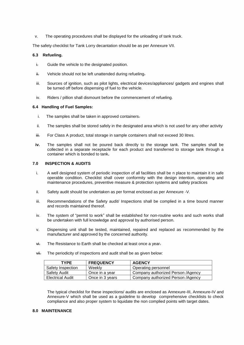
vii. The periodicity of inspections and audit shall be as given below:
TYPE FREQUENCY AGENCY
Safety Inspection Weekly Operating personnel
Safety Audit Once in a year Company authorized Person /Agency
Electrical Audit Once in 3 years Company authorized Person /Agency
The typical checklist for these inspections/ audits are enclosed as Annexure-III, Annexure-IV and Annexure-V which shall be used as a guideline to develop comprehensive checklists to check compliance and also proper system to liquidate the non complied points with target dates.
8.0 MAINTENANCE

8.1 GENERAL
i. A comprehensive maintenance system of all facilities shall be formulated for safe operable
condition.
ii. Preventive maintenance schedules shall be drawn for all equipment, in accordance with manufacturer‘s recommendations, and established mandatory / recommendatory standards. Records of all preventive maintenance undertaken shall be maintained.
iii. Repairs involving non routine maintenance work, shall be carried out after issuance of work
permit, as per the procedure and format enclosed as annexure – VI (a) and VI (b).
iv. The work permit shall be issued by company authorized person or dealer or manager, at the retail outlet, as per the class of activities detailed in item (v) & (vi) given below.
v. Work Permits issued by Dealer / Manager or company authorized person
The following activities involving maintenance of operational area & office requires work permits to be issued by dealer/ manager or company authorized person to contractor or his authorized person.
a. Access to a building / canopy roof. b. Access to a building canopy cavity. c. Electrical switch Board work. d. Excavation including Forecourts upto 1 meter depth. e. Forecourt surface repair. f. Water Removal from Under Ground Tank through hand pump g. Repair of Electrical and Electronic equipments inside hazardous area (Operation of all
electrical and electronic instruments inside hazardous areas, unless certified intrinsically safe)
h. Promotional activities on forecourts. i. Signage, including canopy signage / lighting works. j. Replacement/ installation of Dispensing Units.
vi. Work Permits issued by company authorized personnel only
The following activities involving maintenance of Operational area & office requires work permits to be issued by company authorized person to contractor or his authorized person a. Repair / rework / cleaning of the tanks and pipeline work b. Tank Removal and Decommissioning. c. Non-routine maintenance / replacement / major electrical work within hazardous area. d. Entry in Oxygen Deficient / inert gas area. e. Pneumatic / Hydrostatic pressure testing. f. Cleaning of Oil interceptor, Oil/water separator etc., g. Hot work including but not limited to welding / grinding / gas cutting. h. Demolition and revamping (remodeling). i. All activities capable of producing a spark inside a hazardous area. j. Excavation including Forecourts exceeding 1 meter depth k. Concrete cutting in the hazardous Zone. l. Setting up of temporary equipment including product recovery equipment e.g. compressor,
water/sand blasting equipment etc. 9.0 SAFETY EQUIPMENT
i. Each dispensing unit shall be provisioned with 1 no. ISI marked 9 kg DCP Fire Extinguishers
placed near the island.
ii. Minimum 1 no. 4.5 kg CO2 fire extinguisher conforming to IS: 2878 shall be available in each electrical meter room.
iii. Minimum 4 nos. sand buckets filled with dry sand should be available.
iv. All employees must be conversant with the safe handling of petroleum products and have first-hand knowledge of fire fighting & emergency handling.
v. Only insulated pliers / screw drivers, non-sparking tools and flameproof torch shall be used.
vi. Periodic tests shall be carried out by competent / authorized persons, as applicable and records shall be maintained.
vii. Fire extinguishers are to be periodically tested and maintained as per IS standard. viii. The fire extinguishers are to be checked, tested and maintained as per following schedule &
complying with IS standard:
Visual check of the extinguisher : Daily
Condition of DCP, Hose, Nozzle and safety clip : Every month
Weight checking of CO2 Cartridge : Every Quarter
Performance Testing & DCP Extinguisher : Every Year
Pressure Testing of Extinguisher : Every Three years 10.0 EMERGENCY PLAN AND PROCEDURE i. A comprehensive ERDMP shall be developed in accordance to the Petroleum and Natural Gas
Regulatory Board (Codes of Practices for Emergency Response and Disaster Management Plan (ERDMP)) Regulations, 2010. The copies of the ERDMP shall be available to all personne.
ii. Provision of minimum 2 points for emergency shutdown. iii. The Operating Company having control shall draw an operational emergency plan incorporating
the following:
a) Major failure of fittings resulting in spillage
b) Accidents or other emergencies,
c) Electrical Emergencies
d) Civil emergencies
e) Any other risk arising from the existence or operation
The above emergency plan shall be disseminated amongst all personnel involved and ensured that they understand their roles and responsibilities.
iv. The Retail Outlet in-charge shall maintain close liaison with Fire Service, Police and District
Authorities.
v. Important telephone numbers for emergency use shall be displayed prominently. vi. Means of communication shall be always at the disposal of the In charge of the Retail Outlet. vii. Emergency Action Plan should be tested with mock drill at least once a year. viii. First Aid Kit shall contain items to handle possible emergencies as per State Factories Rules.
ix. Electrical Shock treatment chart written in Bilingual - English & local languages. RO attendants shall be given training on how to treat an electrocuted person before help from a doctor is available.
11.0 COMPETENCE - ASSURANCE AND ASSESSMENT
11.1 The objective is to provide good understanding of all the facets of dispensing activities including
operations, procedures, maintenance and hazards of Petroleum and the risks associated with handling of the product. Training shall ensure that the jobs are performed in accordance with the laid down procedures and practices.
i. Every entity shall develop, implement, and maintain a written training plan to instruct all
Petroleum Retail Outlet personnel with respect to the following:
a. Carrying out the emergency procedures that relate to their duties as set out in the
procedure manual and providing first aid.
b. Permanent maintenance, operating, and supervisory personnel with respect to the
following:
i. The basic operations carried out.
ii. The characteristics and potential hazards of dispensing station.
iii. The methods of carrying out their duties of maintaining and operating the PRO as set
out in the manual of operating, maintenance and transfer procedures.
iv. Fire prevention, including familiarization with the fire control plan, fire fighting, the
potential causes of fire/ accident and the types, sizes, and likely consequences of a
fire/ accident.
v. Recognizing situations when it is necessary for the person to obtain assistance in
order to maintain the security.
11.2 Each oil company shall develop training module of their own which should include inter-alia of the
following :
a) Hazardous nature of product handled. b) Familiarization with operational procedures & practices. c) Hands on experience on operation of equipment. d) Knowledge of emergency and manual shut down systems e) Immediate and effective isolation of any spill f) Safety features and accident prevention. g) Fire fighting facilities, its upkeep and operation. h) Evacuation and safe egress of the vehicles in an emergency. i) Housekeeping j) Decantation k) First aid l) Dos & Don‘ts m) Emergency plan/drills
11.3 Records for the training and refresher courses shall be maintained.
12.0 CUSTOMER SAFETY & AWARENESS 12.1 Display of important information:
i. The particulars of license, emergency telephone nos. of local fire service, police and marketing
company shall be conspicuously displayed.
ii. Suitable caution boards/ pictographs shall be displayed at areas where required.
12.2 DOs & DON’Ts during Refueling.
DOs i. Switch off the engine before commencement of refueling. ii. Ensure a 9 kg DCP Fire Extinguisher is available near the Dispenser.
iii. In case of any spill, overflow of product, fire/smoke observed, press the ―EMERGENCY
STOP‖ button on the Dispenser. DON’Ts i. Do not start the engine / drive away the vehicle till the filling nozzle has been disconnected
from the filler cap of the vehicle. ii. Do not refuel the vehicle during the period MS/HSD is being decanted into the tank. iii.
Do not Smoke
iv. Do not use naked flame v. Do not Operate Mobile Phones
Annexure – I
Zone classification for Retail Outlets
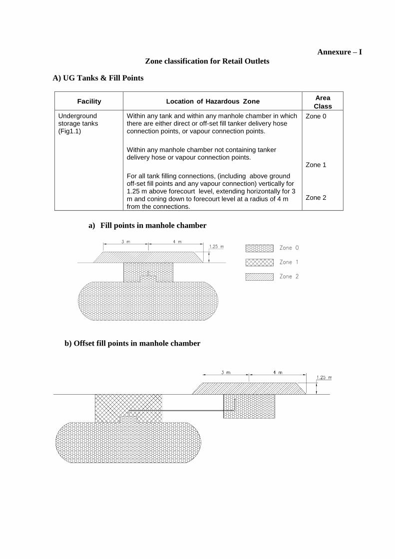
A) UG Tanks & Fill Points
Facility Location of Hazardous Zone Area
Class
Underground storage tanks (Fig1.1)
Within any tank and within any manhole chamber in which there are either direct or off-set fill tanker delivery hose connection points, or vapour connection points.
Within any manhole chamber not containing tanker delivery hose or vapour connection points.
For all tank filling connections, (including above ground off-set fill points and any vapour connection) vertically for 1.25 m above forecourt level, extending horizontally for 3 m and coning down to forecourt level at a radius of 4 m from the connections.
Zone 0 Zone 1
Zone 2
a) Fill points in manhole chamber
b) Offset fill points in manhole chamber
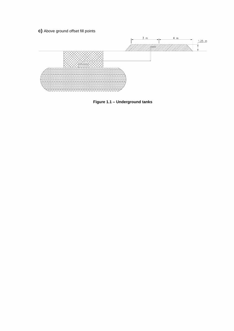
c) Above ground offset fill points
Figure 1.1 – Underground tanks

B) Vent Pipes
Facility Location of Hazardous Zone Area
Class
Vent pipes for underground storage tanks
(Fig 1.2)
Within a radius of 3 m in all directions of the open end of any vent pipe.
The area below the Zone 1 area of the vent pipe, for a radius of 3 m around the discharge point and down to ground level.
Zone 1
Zone 2
Storage tank vent pipe without vapour emission control
Figure 1.2 – Vent pipes
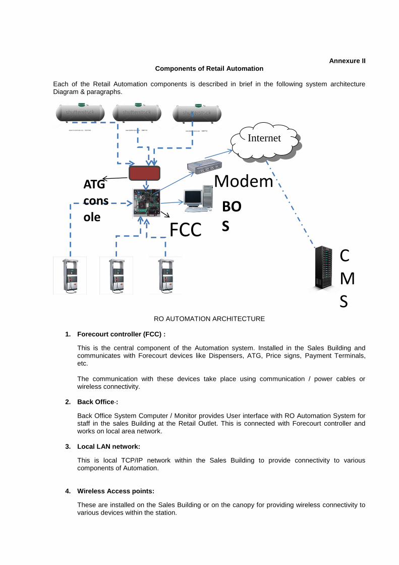
Annexure II
Components of Retail Automation Each of the Retail Automation components is described in brief in the following system architecture Diagram & paragraphs.
RO AUTOMATION ARCHITECTURE
1. Forecourt controller (FCC) :
This is the central component of the Automation system. Installed in the Sales Building and communicates with Forecourt devices like Dispensers, ATG, Price signs, Payment Terminals, etc.
The communication with these devices take place using communication / power cables or wireless connectivity.
2. Back Office :
Back Office System Computer / Monitor provides User interface with RO Automation System for staff in the sales Building at the Retail Outlet. This is connected with Forecourt controller and works on local area network.
3. Local LAN network:
This is local TCP/IP network within the Sales Building to provide connectivity to various components of Automation.
4. Wireless Access points:
These are installed on the Sales Building or on the canopy for providing wireless connectivity to various devices within the station.
Internet
BOS
Modem
FCC
C
CMS
ATG console
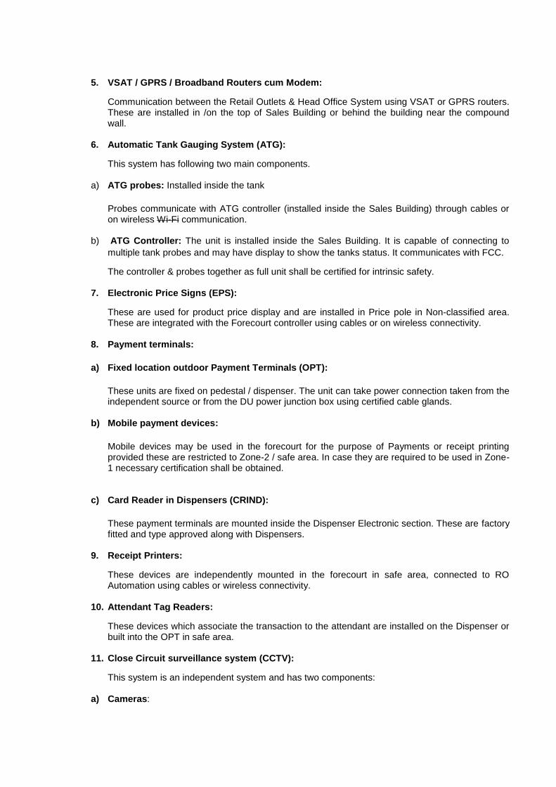
5. VSAT / GPRS / Broadband Routers cum Modem:
Communication between the Retail Outlets & Head Office System using VSAT or GPRS routers. These are installed in /on the top of Sales Building or behind the building near the compound wall.
6. Automatic Tank Gauging System (ATG):
This system has following two main components. a) ATG probes: Installed inside the tank
Probes communicate with ATG controller (installed inside the Sales Building) through cables or on wireless Wi-Fi communication.
b) ATG Controller: The unit is installed inside the Sales Building. It is capable of connecting to
multiple tank probes and may have display to show the tanks status. It communicates with FCC.
The controller & probes together as full unit shall be certified for intrinsic safety. 7. Electronic Price Signs (EPS):
These are used for product price display and are installed in Price pole in Non-classified area. These are integrated with the Forecourt controller using cables or on wireless connectivity.
8. Payment terminals:
a) Fixed location outdoor Payment Terminals (OPT):
These units are fixed on pedestal / dispenser. The unit can take power connection taken from the independent source or from the DU power junction box using certified cable glands.
b) Mobile payment devices:
Mobile devices may be used in the forecourt for the purpose of Payments or receipt printing provided these are restricted to Zone-2 / safe area. In case they are required to be used in Zone-1 necessary certification shall be obtained.
c) Card Reader in Dispensers (CRIND):
These payment terminals are mounted inside the Dispenser Electronic section. These are factory fitted and type approved along with Dispensers.
9. Receipt Printers:
These devices are independently mounted in the forecourt in safe area, connected to RO Automation using cables or wireless connectivity.
10. Attendant Tag Readers:
These devices which associate the transaction to the attendant are installed on the Dispenser or built into the OPT in safe area.
11. Close Circuit surveillance system (CCTV):
This system is an independent system and has two components: a) Cameras:

Mounted on the top of Building / canopy / canopy columns or on independent pedestal. Needs power and communication cables to be connected to DVR / NVR.
b) DVR / NVR:
Video Recorders installed in the Sales Building. Records the images from the various cameras.
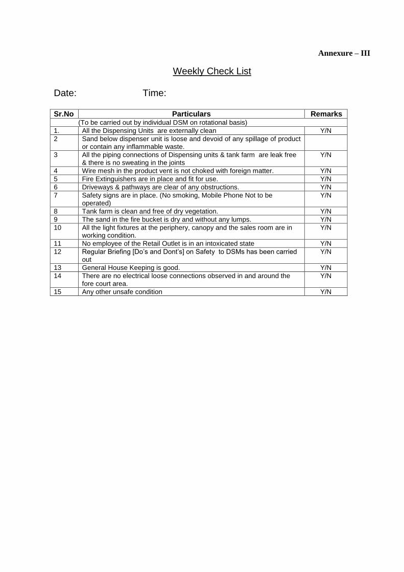
Annexure – III
Weekly Check List Date: Time: Sr.No Particulars Remarks (To be carried out by individual DSM on rotational basis)
1. All the Dispensing Units are externally clean Y/N
2 Sand below dispenser unit is loose and devoid of any spillage of product or contain any inflammable waste.
3 All the piping connections of Dispensing units & tank farm are leak free & there is no sweating in the joints
Y/N
4 Wire mesh in the product vent is not choked with foreign matter. Y/N
5 Fire Extinguishers are in place and fit for use. Y/N
6 Driveways & pathways are clear of any obstructions. Y/N
7 Safety signs are in place. (No smoking, Mobile Phone Not to be operated)
Y/N
8 Tank farm is clean and free of dry vegetation. Y/N
9 The sand in the fire bucket is dry and without any lumps. Y/N
10 All the light fixtures at the periphery, canopy and the sales room are in working condition.
Y/N
11 No employee of the Retail Outlet is in an intoxicated state Y/N
12 Regular Briefing [Do‘s and Dont‘s] on Safety to DSMs has been carried out
Y/N
13 General House Keeping is good. Y/N
14 There are no electrical loose connections observed in and around the fore court area.
Y/N
15 Any other unsafe condition Y/N
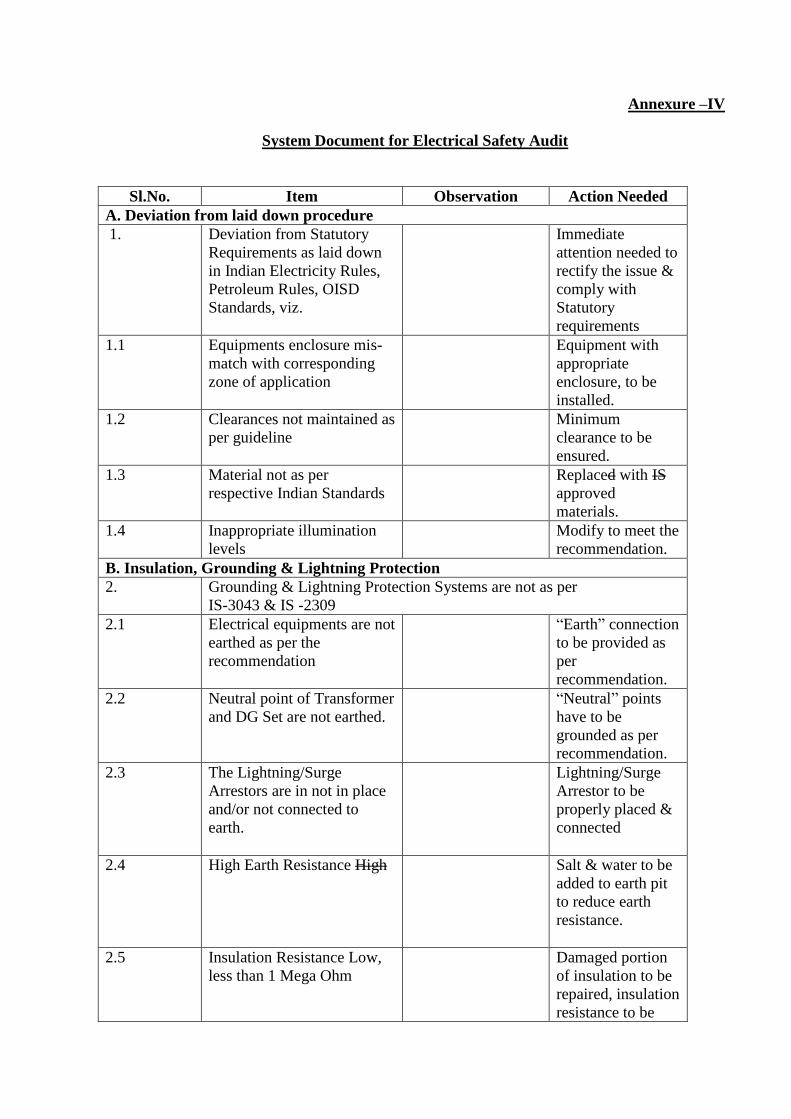
Annexure –IV
System Document for Electrical Safety Audit
Sl.No. Item Observation Action Needed
A. Deviation from laid down procedure
1. Deviation from Statutory
Requirements as laid down
in Indian Electricity Rules,
Petroleum Rules, OISD
Standards, viz.
Immediate
attention needed to
rectify the issue &
comply with
Statutory
requirements
1.1 Equipments enclosure mis-
match with corresponding
zone of application
Equipment with
appropriate
enclosure, to be
installed.
1.2 Clearances not maintained as
per guideline
Minimum
clearance to be
ensured.
1.3 Material not as per
respective Indian Standards
Replaced with IS
approved
materials.
1.4 Inappropriate illumination
levels
Modify to meet the
recommendation.
B. Insulation, Grounding & Lightning Protection
2. Grounding & Lightning Protection Systems are not as per
IS-3043 & IS -2309
2.1 Electrical equipments are not
earthed as per the
recommendation
“Earth” connection
to be provided as
per
recommendation.
2.2 Neutral point of Transformer
and DG Set are not earthed.
“Neutral” points
have to be
grounded as per
recommendation.
2.3 The Lightning/Surge
Arrestors are in not in place
and/or not connected to
earth.
Lightning/Surge
Arrestor to be
properly placed &
connected
2.4 High Earth Resistance High
Salt & water to be
added to earth pit
to reduce earth
resistance.
2.5 Insulation Resistance Low,
less than 1 Mega Ohm
Damaged portion
of insulation to be
repaired, insulation
resistance to be
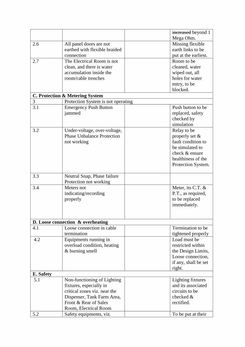
increased beyond 1
Mega Ohm.
2.6 All panel doors are not
earthed with flexible braided
connection
Missing flexible
earth links to be
put at the earliest.
2.7 The Electrical Room is not
clean, and there is water
accumulation inside the
room/cable trenches
Room to be
cleaned, water
wiped out, all
holes for water
entry, to be
blocked.
C. Protection & Metering System
3 Protection System is not operating
3.1 Emergency Push Button
jammed
Push button to be
replaced, safety
checked by
simulation
3.2 Under-voltage, over-voltage,
Phase Unbalance Protection
not working
Relay to be
properly set &
fault condition to
be simulated to
check & ensure
healthiness of the
Protection System.
3.3 Neutral Snap, Phase failure
Protection not working
3.4 Meters not
indicating/recording
properly
Meter, its C.T. &
P.T., as required,
to be replaced
immediately.
D. Loose connection & overheating
4.1 Loose connection in cable
termination
Termination to be
tightened properly
4.2 Equipments running in
overload condition, heating
& burning smell
Load must be
restricted within
the Design Limits,
Loose connection,
if any, shall be set
right.
E. Safety
5.1 Non-functioning of Lighting
fixtures, especially in
critical zones viz. near the
Dispenser, Tank Farm Area,
Front & Rear of Sales
Room, Electrical Room
Lighting fixtures
and its associated
circuits to be
checked &
rectified.
5.2 Safety equipments, viz. To be put at their
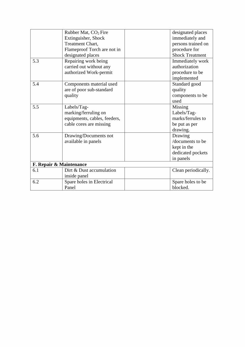
Rubber Mat, CO2 Fire
Extinguisher, Shock
Treatment Chart,
Flameproof Torch are not in
designated places
designated places
immediately and
persons trained on
procedure for
Shock Treatment
5.3 Repairing work being
carried out without any
authorized Work-permit
Immediately work
authorization
procedure to be
implemented
5.4 Components material used
are of poor sub-standard
quality
Standard good
quality
components to be
used
5.5 Labels/Tag-
marking/ferruling on
equipments, cables, feeders,
cable cores are missing
Missing
Labels/Tag-
marks/ferrules to
be put as per
drawing.
5.6 Drawing/Documents not
available in panels
Drawing
/documents to be
kept in the
dedicated pockets
in panels
F. Repair & Maintenance
6.1 Dirt & Dust accumulation
inside panel
Clean periodically.
6.2 Spare holes in Electrical
Panel
Spare holes to be
blocked.
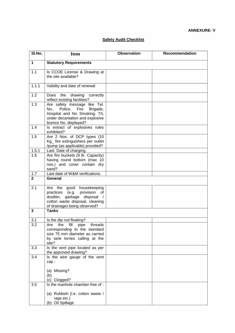
ANNEXURE- V
Safety Audit Checklist
Sl.No. Item Observation
Recommendation
1 Statutory Requirements
1.1 Is CCOE License & Drawing at the site available?
1.1.1 Validity and date of renewal
1.2 Does the drawing correctly reflect existing facilities?
1.3 Are safety message like Tel. No., Police, Fire Brigade, Hospital and No Smoking, T/L under decantation and explosive licence No. displayed?
1.4 Is extract of explosives rules exhibited?
1.5 Are 2 Nos. of DCP types (10 Kg_ fire extinguishers per outlet /pump (as applicable) provided?
1.5.1 Last. Date of charging.
1.6 Are fire buckets (9 ltr. Capacity) having round bottom (max 10 nos.) and cover contain dry sand?
1.7 Last date of W&M verifications.
2 General
2.1 Are the good housekeeping practices (e.g. provision of dustbin, garbage disposal / cotton waste disposal, cleaning of drainage) being observed?
3 Tanks
3.1 Is the dip rod floating?
3.2 Are the fill pipe threads corresponding to the standard size 75 mm diameter as carried by tank lorries calling at the site?
3.3 Is the vent pipe located as per the approved drawing?
3.4 Is the wire gauge of the vent cap :
(a) Missing? (b)
(c) Clogged?
3.5 Is the manhole chamber free of :
(a) Rubbish (i.e. cotton waste / rags etc.)
(b) Oil Spillage

3.6 Are tank curb walls / pipe railings in good condition?
3.7 Are lorry discharge points distinctively painted as per our standard?
3.8 Are the following securely closed :
(a) Lorry discharge points? (b) Dip pipe?
3.9 Are sank buckets and fire extinguishers positioned near the T/L during T/L unloading?
3.10 Is bonding wire connected while decanting the tanklorry?
4 Pumps
4.1 Are the pumps : (a) Clean? (b) Leaky?
4.2 Are the electric motors properly earthened?
(a) Located as per the drawing? (b) Easily accessible?
4.3 Is there any loose wiring in the pump?
4.4 Are flameproof boxes closed properly?
4.5 Is dry sand filled in the gap below pump in pump pedestal?
5 Building & other facilities
5.1 Are any other flammable materials like LPG cylinders, cardboard cartons etc., are stored in the generator room?
5.2 Whether generator room properly ventilated, clean and dry?
6 Electrical
6.1 Is the electrical system as per our standard?
6.2 Is there any loose wiring in the switch board?
6.3 Is the earthing provided as per new standards?
6.4 Are the light fixtures in good condition?
6.5 Are the cables with FLP glands fitted to pumps?
6.6 Are all the equipments a labeled?
6.7 Are all the cable / wire terminations tightened?
6.8 Is there any dirt or dust inside the electrical panels?
6.9 Are all spare cable entry holes in all electrical panels blocked?

6.10 All panel doors are earthed with flexible braided connection?
6.11 Are all electrical equipments earthed as per recommendations?
6.12 Are Neutral point of transformer and DG set earthed?
6.13 The lightning / surge arrestors are in place and in working condition and are connected to earth?
6.14 Is the insulation resistance of each feeder is more than 1 Mega Ohm?
6.15 Is the voltage between the neutral and earth limited to 3V?
6.16 Is the electrical room maintained clean, free from water accumulation?
6.17 Is there any undue heating in any parts of any equipment?
6.18 Is the shock treatment chart is available in electrical room and all concerned persons are trained on the treatment procedures?
7
Tank Lorry
7.1 Is the earth wire connected properly during decantation?
7.2 Is fire extinguisher available?
7.3 Is the fire extinguisher kept accessible?
7.4 Is PCVO crew aware of fire fighting methods?
7.5 Is dip pipe kept closed while decanting?
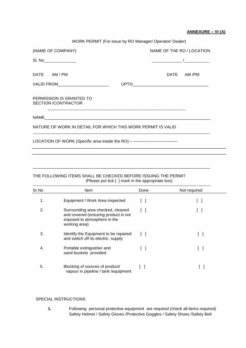
ANNEXURE – VI (A)
WORK PERMIT (For issue by RO Manager/ Operator/ Dealer)
(NAME OF COMPANY) NAME OF THE RO / LOCATION Sl. No______________ _____________ /___________ DATE AM / PM DATE AM /PM VALID FROM______________________ UPTO_________________________________ PERMISSION IS GRANTED TO SECTION /CONTRACTOR ____________________________________________________________ NAME________________________________________________________________________ NATURE OF WORK IN DETAIL FOR WHICH THIS WORK PERMIT IS VALID _____________________________________________________________________________ LOCATION OF WORK (Specific area inside the RO) – --------------------------------
_____________________________________________________________________________ THE FOLLOWING ITEMS SHALL BE CHECKED BEFORE ISSUING THE PERMIT
(Please put tick [ ] mark in the appropriate box) ----------------------------------------------------------------------------------------------------------------------- ---------- Sr.No Item Done Not required
1. Equipment / Work Area inspected [ ] [ ]
2. Surrounding area checked, cleaned [ ] [ ]
and covered (ensuring product is not exposed to atmosphere in the working area)
3. Identify the Equipment to be repaired [ ] [ ] and switch off its electric supply
4. Portable extinguisher and [ ] [ ] sand buckets provided
5. Blocking of sources of product/ [ ] [ ]
vapour in pipeline / tank /equipment
SPECIAL INSTRUCTIONS
1. Following personal protective equipment are required (check all items required)
Safety Helmet / Safety Gloves /Protective Goggles / Safety Shoes /Safety Belt
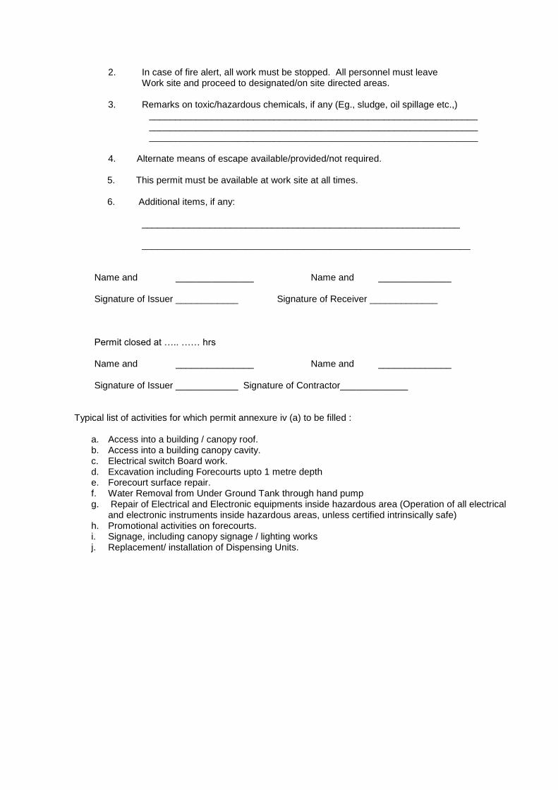
2. In case of fire alert, all work must be stopped. All personnel must leave Work site and proceed to designated/on site directed areas.
3. Remarks on toxic/hazardous chemicals, if any (Eg., sludge, oil spillage etc.,)
_______________________________________________________________ _______________________________________________________________ _______________________________________________________________
4. Alternate means of escape available/provided/not required.
5. This permit must be available at work site at all times. 6. Additional items, if any:
_____________________________________________________________ _______________________________________________________________
Name and _______________ Name and ______________ Signature of Issuer ____________ Signature of Receiver _____________ Permit closed at ….. …… hrs Name and _______________ Name and ______________ Signature of Issuer ____________ Signature of Contractor_____________
Typical list of activities for which permit annexure iv (a) to be filled :
a. Access into a building / canopy roof. b. Access into a building canopy cavity. c. Electrical switch Board work. d. Excavation including Forecourts upto 1 metre depth e. Forecourt surface repair. f. Water Removal from Under Ground Tank through hand pump g. Repair of Electrical and Electronic equipments inside hazardous area (Operation of all electrical
and electronic instruments inside hazardous areas, unless certified intrinsically safe) h. Promotional activities on forecourts. i. Signage, including canopy signage / lighting works j. Replacement/ installation of Dispensing Units.
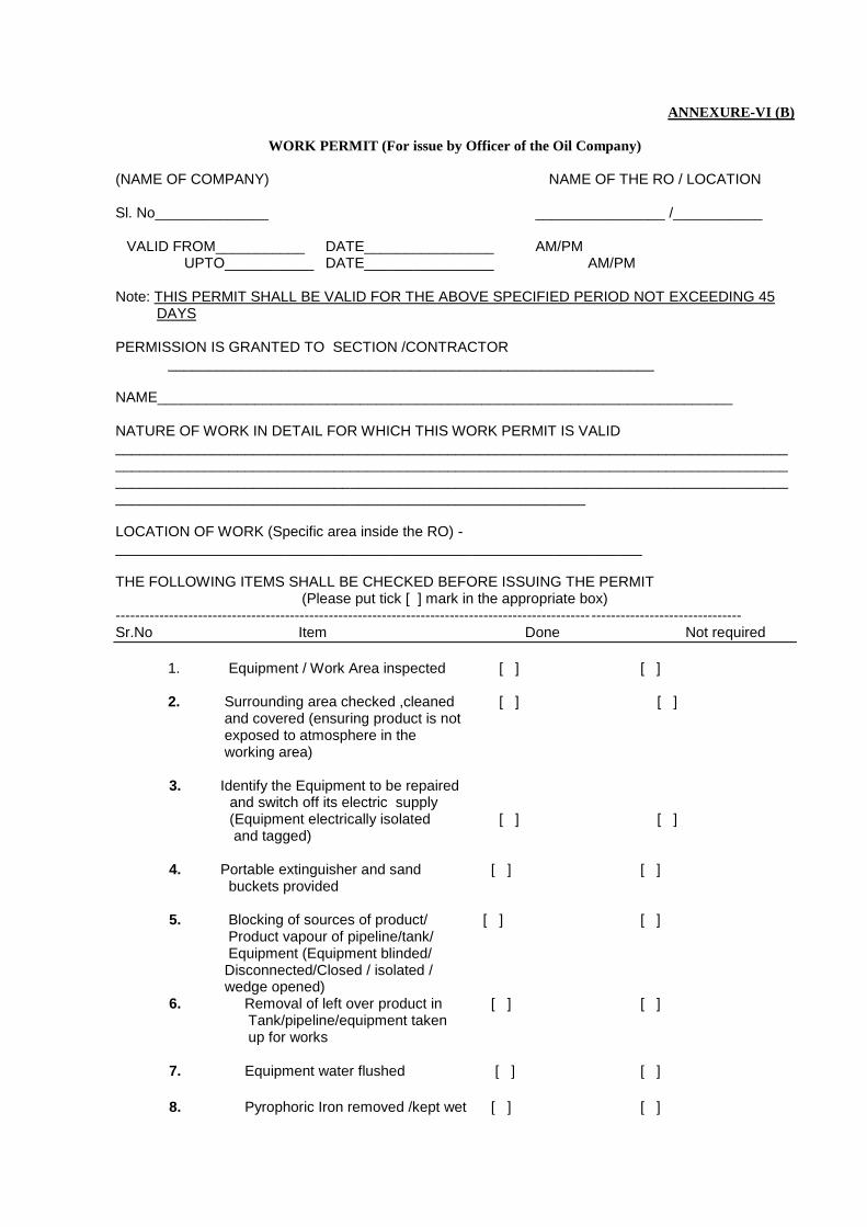
ANNEXURE-VI (B)
WORK PERMIT (For issue by Officer of the Oil Company)
(NAME OF COMPANY) NAME OF THE RO / LOCATION Sl. No______________ ________________ /___________
VALID FROM___________ DATE________________ AM/PM UPTO___________ DATE________________ AM/PM Note: THIS PERMIT SHALL BE VALID FOR THE ABOVE SPECIFIED PERIOD NOT EXCEEDING 45
DAYS PERMISSION IS GRANTED TO SECTION /CONTRACTOR ____________________________________________________________ NAME_______________________________________________________________________ NATURE OF WORK IN DETAIL FOR WHICH THIS WORK PERMIT IS VALID ___________________________________________________________________________________________________________________________________________________________________________________________________________________________________________________________________________________________________________________ LOCATION OF WORK (Specific area inside the RO) - _________________________________________________________________ THE FOLLOWING ITEMS SHALL BE CHECKED BEFORE ISSUING THE PERMIT
(Please put tick [ ] mark in the appropriate box) -------------------------------------------------------------------------------------------------- ------------------------------- Sr.No Item Done Not required
1. Equipment / Work Area inspected [ ] [ ]
2. Surrounding area checked ,cleaned [ ] [ ]
and covered (ensuring product is not exposed to atmosphere in the working area)
3. Identify the Equipment to be repaired and switch off its electric supply (Equipment electrically isolated [ ] [ ] and tagged)
4. Portable extinguisher and sand [ ] [ ] buckets provided
5. Blocking of sources of product/ [ ] [ ] Product vapour of pipeline/tank/ Equipment (Equipment blinded/ Disconnected/Closed / isolated / wedge opened) 6. Removal of left over product in [ ] [ ] Tank/pipeline/equipment taken up for works
7. Equipment water flushed [ ] [ ]
8. Pyrophoric Iron removed /kept wet [ ] [ ]
9. Proper ventilation and lighting [ ] [ ] Provided 10. Gas test done, found gas free [ ] [ ]
11. Standby personnel provided [ ] [ ]
(confined space entry viz tank entry etc)
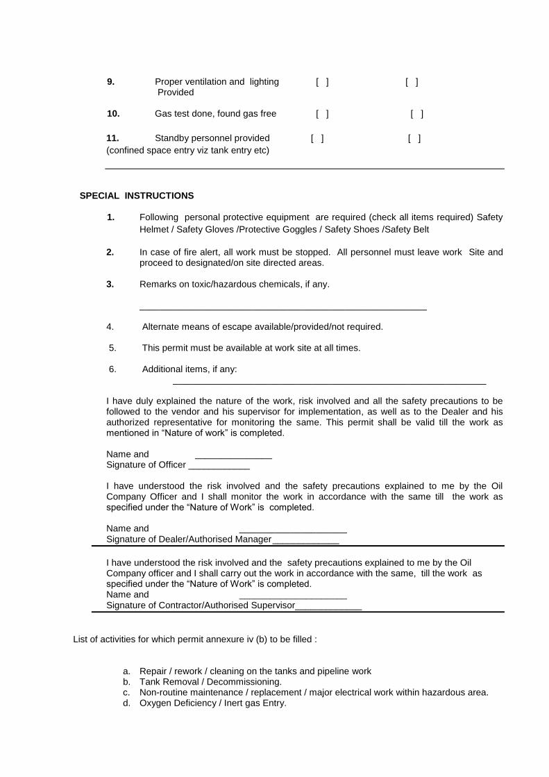
SPECIAL INSTRUCTIONS
1. Following personal protective equipment are required (check all items required) Safety
Helmet / Safety Gloves /Protective Goggles / Safety Shoes /Safety Belt
2. In case of fire alert, all work must be stopped. All personnel must leave work Site and
proceed to designated/on site directed areas. 3. Remarks on toxic/hazardous chemicals, if any.
________________________________________________________ 4. Alternate means of escape available/provided/not required. 5. This permit must be available at work site at all times. 6. Additional items, if any: _____________________________________________________________ I have duly explained the nature of the work, risk involved and all the safety precautions to be followed to the vendor and his supervisor for implementation, as well as to the Dealer and his authorized representative for monitoring the same. This permit shall be valid till the work as mentioned in ―Nature of work‖ is completed.
Name and _______________ Signature of Officer ____________
I have understood the risk involved and the safety precautions explained to me by the Oil Company Officer and I shall monitor the work in accordance with the same till the work as specified under the ―Nature of Work‖ is completed. Name and _____________________ Signature of Dealer/Authorised Manager _____________
I have understood the risk involved and the safety precautions explained to me by the Oil Company officer and I shall carry out the work in accordance with the same, till the work as specified under the ―Nature of Work‖ is completed.
Name and _____________________ Signature of Contractor/Authorised Supervisor_____________
List of activities for which permit annexure iv (b) to be filled :
a. Repair / rework / cleaning on the tanks and pipeline work b. Tank Removal / Decommissioning. c. Non-routine maintenance / replacement / major electrical work within hazardous area. d. Oxygen Deficiency / Inert gas Entry.

e. Pneumatic / Hydrostatic pressure testing. f. Oil interceptor (like Oil/water separator etc.,) cleaning – where entry into the interceptor
is required. g. Hot work including but not limited to welding / grinding / gas cutting. h. Demolition / revamping. i. All activities capable of producing a spark inside a hazardous area.
j. Excavation including Forecourts exceeding 1 metre depth k. Concrete cutting in the hazardous Zone. l. Setting up of temporary equipment including product recovery equipment E.g. Compressor, water/sand blasting equipment etc.

ANNEXURE - VII
Safety Checklist for Tank-Truck Decanting at Retail Outlet
Sr.No Activity Check
1 Only one tank-truck is being decanted at the retail outlet at a given time
2 Tank truck to be positioned in the demarcated area and area to be cordoned off.
3 Ensure no ignition source in the vicinity of the tanker.
4 Tank-truck has CCOE-approved spark arrestor
5 Parking brakes and gear must be engaged at all times. Place wheel chokes to prevent movement of tanker.
6 The engine of the tank-truck has been switched off and the battery switch is in ‗off‘ position
7 ‗No Smoking ‗ board is displayed prominently
8 Ensure connecting the TT to the earthing bus and proper bonding prior to any decantation action.
Ensure leakproof coupling on the hoses both on tank side and tanker side.
9 Dip pipe of the underground tank opening has been kept closed to avoid any vapour accumulation during decantation
10 The engine of the tank-truck has been switched off and the battery switch is in ‗off‘ position
11 Mobile phones of the tank-truck crew and the retail outlet staff assisting them have been switched off / Mobile phone should not be operated
12 The 10 kg / 9kg DCP fire-extinguisher of the tank truck has been taken out and kept next to the tank-truck
13 Fire buckets are easily accessible
15 Ensure rubber hose with external continuity wire and suitable end coupling only is being used.
16 Only bonded metallic bucket is being used for drawing samples
17 The dirver, khalasi and the designated retail outlet supervisor are present during the entire process of decantation
Verified that all precautions have been taken with regard to decantation as detailed above: (Signature & Signature & (Name of Driver) (Name /Designation of
authorized RO staff)
Annexure – VIII
REFERENCES
i. Petroleum Rules – 2002 ii. Marketing Discipline Guidelines iii. IS 2062 : Steel for General Structural Purpose iv. IS 1239: Part 1: and IS 1239: Part 2 : Steel Tubes and Other Wrought Steel Fittings. v. IS-5572 : Hazardous Area Classification vi. IS 10987 : Code of Practice for Design, Fabrication, Testing and Installation of Underground /
Above ground Horizontal Cylindrical Storage Tanks for Petroleum Products. vii. IS 2309 : Code of Practice for the Protection of Building and Allied Structures Against Lighting viii. IS 3043 : Code of Practice for Earthing ix. UL 1316: Glass-Fiber-Reinforced Plastic Underground Storage Tanks for Petroleum Products,
Alcohols, and Alcohol-Gasoline Mixtures. x. UL 971 : Nonmetallic Underground Piping for Flammable Liquids xi. EN 14125 : Thermoplastic and Flexible Metal Pipe Work for Underground Installation at Petrol
Filling Station xii. IS-1978 : Indian Standard Specification for Line Pipe xiii. UL 87- Power Operated Dispensing Device for Petroleum Product or Relevant Standards xiv. UL 79- Power Operated Pumps for Petroleum Dispensing Products or Relevant Standards xv. IS: 5571 - Guide for selection and installation of Electrical equipment in hazardous areas.
Schedule 2 : “Storage, Handling and Dispensing at Auto LPG Dispensing Stations”
Schedule 2 : “Storage, Handling and Dispensing at Auto LPG Dispensing Stations”
CONTENTS
------------------------------------------------------------------------------------------------------------ S.NO. DESCRIPTION ------------------------------------------------------------------------------------------------------------ 1.0 SCOPE
2.0 DEFINITIONS
3.0 LAYOUT & FACILITIES 4.0 OPERATING PROCEDURES 5.0 INSPECTION & MAINTENANCE 6.0 TESTING OF RELIEF AND PROTECTION SYSTEM 7.0 SAFETY INSPECTIONS / AUDIT 8.0 EMERGENCY PLAN AND PROCEDURE 9.0 COMPETENCE ASSURANCE AND ASSESSMENT 10.0 CUSTOMER SAFETY & AWARENESS
------------------------------------------------------------------------------------------------------------ ANNEXURES I Typical Retail Outlet Layout II Piping & Instrumentation Diagram for
Auto LPG Dispensing Station
III Commissioning & Decommissioning Procedures IV Inspection of the Auto LPG Dispensing Station V REFERENCES
1.0 SCOPE
This technical standard and specifications including safety standards lays down the minimum requirements in design, operation, inspection, maintenance, training, consumer safety at Auto LPG Dispensing Stations (ALDS). It does not cover the certification or fitness requirements of vehicles using Auto LPG.
2.0 DEFINITIONS
a. ―Auto LPG‖ means a mixture of certain light hydrocarbons derived from petroleum, which are
gaseous at normal ambient temperature and atmospheric pressure but may be condensed to liquid state at normal ambient temperature by the application of moderate pressure, and which conforms to IS :14861.
b. ―Auto LPG Dispensing Station (ALDS):‖ mean the premises used for storing and dispensing auto
LPG to the motor vehicles for automotive purpose. c. ―Auto LPG Tank‖ mean a steel container for storage and transport of Auto LPG, fitted
permanently in a motor vehicle or vehicle as its fuel tank, for automotive fuel and filled in that position and conforming to IS:14899 and as approved by the Chief Controller of Explosives under Gas Cylinder Rules 1981.
d. ―Bulk Storage‖ means the facilities for storing LPG in stationary pressure vessels exceeding the
capacity of 1000 Lt. These pressure vessels shall conform to the Static & Mobile Pressure Vessels (Unfired) Rules, 1981.
e. ―Dispenser‖ means the equipment provided in the ALDS for delivering LPG to the Auto LPG Tank
of motor vehicles f. ―Emergency shut off Valve‖ means a shut off valve which, in an emergency, operates
automatically or can be operated remotely. g. ―Filling Point‖ means the point of inlet pipe connection of a bulk storage tank for MS/ HSD/ LPG,
where hose is connected for filling the products into the tank. h. ―LPG Tank Truck Unloading Hard Stand‖ means the area specially prepared in a Auto LPG
Dispensing Station beside the LPG fill point for unloading from tank truck to bulk storage vessel. i. ―LPG Vent‖ means the vertical pipe provided on the vessel for discharge of LPG vapours from
safety relief valve at a height of at least 2 meters above the top level of the vessels but not less than 3 meters from the ground level.
j. ―MS /HSD Vent‖ means the vertical pipe open at the top, fitted on an underground tank in Retail
Outlets for breathing. k. ―Retail Outlet/ MS/ HSD Service Station‖ means the segregated area provided with facilities and
specially prepared, for storage and delivering MS/ HSD to the fuel tanks of motor vehicles. l. ―Safety Relief Valve‖ means a pressure relief device fitted on a pressure vessel to protect the
vessel against maximum allowable pressure. m. ―Auto LPG Tank Truck‖ means a truck mounted with a properly designed vessel/tank for
transportation of auto LPG in bulk to the dispensing stations. n. ―Bob tail‖ means a truck mounted with a properly designed vessel/tank with flowmeter pump skid
for transportation of LPG in bulk to the dispensing stations.
3.0 LAYOUT & FACILITIES 3.1 General Guidelines
i. The layout should ensure unobstructed movement of all vehicles together with adequate provision for entry and exit of Tank trucks.
ii. Location of the facilities , equipment , entrance , exit & paving shall be arranged in a such
manner to avoid the risk of any collision amongst the motor vehicles.
iii. The fuel lines shall have a positive segregation with electrical cables.
iv. It is preferable that there should be unobstructed view of the operating and dispensing areas from the salesroom.
v. Access for mobile fire fighting equipment to all the ALDS facilities shall be ensured.
vi. In case of above ground bulk storage vessels, provision of storage of adequate fire water as
stipulated in this standard shall be made.
vii. Provision of escape route for personnel and vehicle in emergency shall be made.
viii. The LPG bulk storage area at ALDS shall be enclosed by an industrial type fencing at least 2 M high erected on a kerb/ toe wall of at least 0.3 M high and fill point shall be at the inner edge of this fencing and area shall be suitably guarded against vehicular impact. Such fence shall have at least two means of exit and the gates of such exits shall open outwards and shall not be self locking.
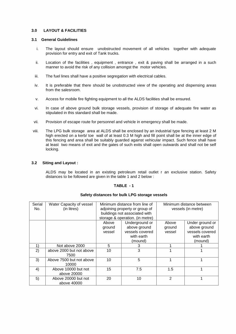
3.2 Siting and Layout :
ALDS may be located in an existing petroleum retail outlet r an exclusive station. Safety distances to be followed are given in the table 1 and 2 below :
TABLE - 1
Safety distances for bulk LPG storage vessels
Serial No.
Water Capacity of vessel (in litres)
Minimum distance from line of adjoining property or group of buildings not associated with
storage & operation. (in metre)
Minimum distance between vessels (in metre)
Above ground vessel
Underground or above ground
vessels covered with earth (mound)
Above ground vessel
Under ground or above ground
vessels covered with earth (mound)
1) Not above 2000 5 3 1 1
2) above 2000 but not above 7500
10 3 1 1
3) Above 7500 but not above 10000
10 5 1 1
4) Above 10000 but not above 20000
15 7.5 1.5 1
5) Above 20000 but not above 40000
20 10 2 1
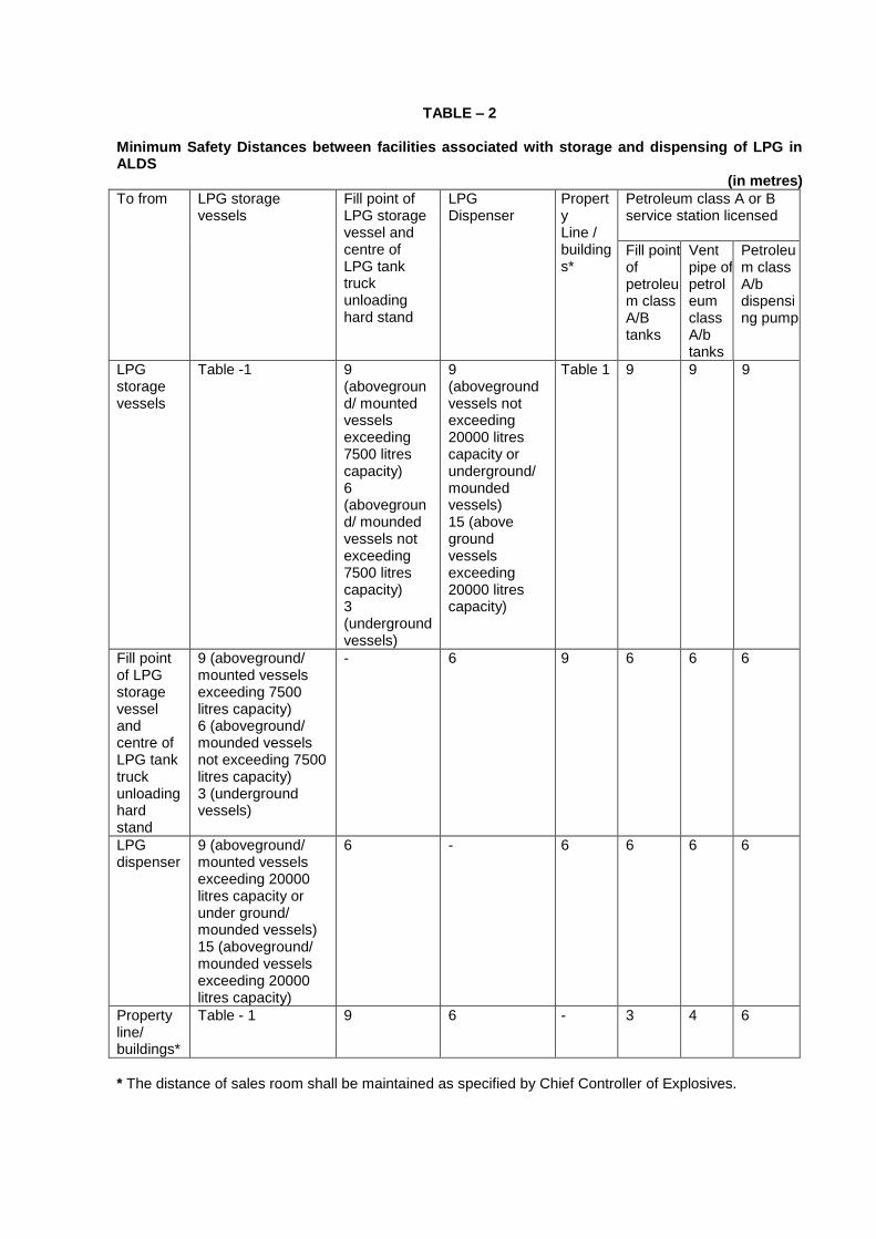
TABLE – 2 Minimum Safety Distances between facilities associated with storage and dispensing of LPG in ALDS
(in metres)
To from LPG storage vessels
Fill point of LPG storage vessel and centre of LPG tank truck unloading hard stand
LPG Dispenser
Property Line / buildings*
Petroleum class A or B service station licensed
Fill point of petroleum class A/B tanks
Vent pipe of petroleum class A/b tanks
Petroleum class A/b dispensing pump
LPG storage vessels
Table -1 9 (aboveground/ mounted vessels exceeding 7500 litres capacity) 6 (aboveground/ mounded vessels not exceeding 7500 litres capacity) 3 (underground vessels)
9 (aboveground vessels not exceeding 20000 litres capacity or underground/ mounded vessels) 15 (above ground vessels exceeding 20000 litres capacity)
Table 1 9 9 9
Fill point of LPG storage vessel and centre of LPG tank truck unloading hard stand
9 (aboveground/ mounted vessels exceeding 7500 litres capacity) 6 (aboveground/ mounded vessels not exceeding 7500 litres capacity) 3 (underground vessels)
- 6 9 6 6 6
LPG dispenser
9 (aboveground/ mounted vessels exceeding 20000 litres capacity or under ground/ mounded vessels) 15 (aboveground/ mounded vessels exceeding 20000 litres capacity)
6 - 6 6 6 6
Property line/ buildings*
Table - 1 9 6 - 3 4 6
* The distance of sales room shall be maintained as specified by Chief Controller of Explosives.
Notes
(i) If the aggregate water capacity of a multi vessel installation exceeds 40 KL, the minimum safety distance from any vessel to the property line/ group of buildings shall not be less than 30 m for above ground vessels and 15 m for under ground vessels.:
(ii) The distances specified above are required to be measured from the nearest point on the
periphery of the vessel. (iii) Minimum 6 m distance shall be kept between LPG bulk storage vessel and Storage vessel of
the other petroleum products s Typical layout of installation is attached as annexure – I. 3.3 Bulk Storage Vessel :
i. The mechanical design of the storage vessel shall be based on following considerations : a. The storage vessel shall be designed in accordance with the codes i.e. PD – 5500, ASME-
Sec VIII, IS:2825 or equivalent duly approved by PESO. Design shall also take into account the requirements specified in Static and Mobile Pressure Vessels (Unfired) Rules 1981.
b. A single code shall be adopted for design, fabrication, inspection and testing i.e. ASTM and
BS shall not be combined. c. Material : Carbon steel conforming to ASTM A516 Grade 60 / 70 or A537 Class I. Micro-
alloyed steel containing Ni, Mo, Va shall not be considered. Maximum specified tensile stress of the material shall be below 80,000 psi.
d. Design Temperature : -27
oC to +55
oC.
e. Design Pressure : Maximum Vapour pressure of LPG conforming to IS: 14861 at 55
oC and
shall be taken as 14.5 kg/cm2.
f. Other Design Considerations
i. Corrosion Allowance : 1.5 mm (minimum)
ii. Radiography : 100 %
iii. Stress relieving : 100% irrespective of thickness.
iv. Wind pressure : as per IS: 875
v. Earthquake pressure : as per IS:1893
vi. Hydrotest pressure : As per Design Code
vii. Additional requirement, if any, on account of design codes/ statutory stipulations shall also be considered.
3.3.1Above Ground Storage Vessel
i. The bulk storage vessel shall be placed on a firm foundation. ii. There shall be single nozzle at the bottom for liquid inlet/ outlet with ROV as first valve. The first
flange shall be at least 3 m away from the shadow of the vessel.

iii. In multi vessel installation, top of the vessels shall be in the same plane.
iv. Suitable arrangement for draining of water from storage vessel shall be provided with double valve.
3.3.2 Mounded / Underground Storage Vessel Mounded / Underground storage vessels shall also conform to the following requirements:
i. The specific consideration shall be given to
a. Internal vapour and hydraulic pressure b. External loading on the vessel c. Internal vacuum
ii. The dimensions (diameter and length) of the vessel shall be decided based on site conditions,
soil mechanics and other design considerations. iii. The vessel shall be protected against corrosion by appropriate anti corrosive coating and
provided with cathodic protection. Alternatively, steel tank can be designed for the service life and shall be taken out of service on completion of design service life with periodic inspections to verify the veracity of design parameters.
iv. The cathodically protected pipelines/ vessels etc. shall be isolated from the unprotected structures /surfaces.
v. Reference points on inner surface of the vessel shall be marked for Non Destructive Testing for
subsequent inspections. vi. The underground vessel shall be installed on a firm foundation and firmly secured to the
foundation so as to prevent movement or floatation.
vii. The underground vessel shall be placed within a concrete or brick masonary pit with a minimum gap of 1 m between the walls of the pit and the vessel as well as in between the vessel.
viii. The vessels shall be covered by earth or sand or any other non corrosive material and thickness of the covering material above the top surface of the vessel shall not be less than 0.5 m
ix. The fittings / mountings on the vessel shall be in such a way that these can be operated and
maintained without disturbing the earth cover. 3.4 Fittings Each storage vessel shall have at least two safety relief valves, two independent level indicating
devices, one independent high level cut off switch with alarm, temperature gauge, pressure gauge, suitable arrangement for water draining etc. Remote operated valve (ROV) shall be provided on all liquid and vapour lines connected to the storage vessel.
3.4.1 Safety Relief Valve
i. Each safety relief valve shall be set to discharge at not more than 110 % of design pressure and have relieving capacity adequate to prevent the maximum pressure in the vessel from exceeding 120 % of the design pressure. Each safety relief valve shall be provided with a lock open type isolation valve between it and the vessel so that one of the two valves can be removed from testing without emptying the vessel.
ii. The set and reset pressure of the safety valve shall meet the requirements of Auto LPG conforming to IS : 14861.
iii. The relieving capacity of the safety valve storing LPG in mounded & underground storage vessel
shall be at least 30 % of that for above ground storage vessel in fire condition. 3.4.2 Emergency Shut off Valve i.e. Remote Operated Valves
i. Emergency shut off valves of remote operated type shall be provided on all liquid & vapour connections i.e filling, discharge, pump by pass & vapour return lines of the bulk storage vessels except those for safety valves / instruments tapping and those not exceeding 3 mm diameter for liquid and 8 mm diameter for vapour. ROV's shall be operable from sales room/control panel and from operating area.
ii. The remote operated valves shall be fire safe valves with a closing time not exceeding 15 seconds.
iii. ROV's shall have an open / closed position indicator.
iv. Additionally, isolation valves of ball type shall be installed at shortest distance from ROV. 3.4.3 Excess flow check valves (EFCV):
i. Excess flow check valve shall be provided on the liquid lines. The closing flow of the EFCV shall not be more than 120 % of the rated flow of the line / as recommended by the manufacturer. Excess flow check valve shall be provided with a breathing arrangement to allow equalisation of pressure.
ii. In closed position, the opening of the EFCV shall not be more than 2 mm2.
3.4.4 Manual Shut Off Valves:
Manual shut off valves shall be provided in all liquid and vapour pipelines as close to ROV as possible. All shut off & isolation valves shall be of quick closing ball type, readily accessible for operation and maintenance under normal & emergency conditions.
3.5 Tank Truck Unloading Facilities
i. The layout of the unloading location shall be such that tank truck being unloaded shall be in drive out position.
ii. Suitable provision shall be made for evacuation of LPG from bulk storage vessels to tank truck to
empty the vessel in case of emergency or for statutory testing.
iii. Tank truck shall be unloaded using hose with the breakaway coupling with isolation arrangement on both ends so that no release of liquid LPG take place at the end of the unloading. Alternatively, loading arms can be provided.
iv. The hose - coupling / flange joint shall be of 300 lb rating with metallic gasket. The hose
coupling shall be provided with a cap or blind flange by which the nozzle can be closed when not in use.
v. The LPG hose used shall conform to Indian standard or API or EN codes.
vi. Hose length shall not be more than 5.5 m.
vii. The pipeline and the hose shall be laid so as to be above the ground to prevent any damage.
The entire assembly shall be suitable supported and be installed in a lockable enclosure.
viii. The fill point shall be provided with non return valve and quick shut off isolation valve. ix. Proper arrangement for earthing & bonding shall be made. x. The vent pipe, if required , shall be at height of at least 3 m from the grade and 6 m away from
potential sources of ignition / likely places of vapour accumulation. 3.6 LPG Pump
LPG pump can be either external or submerged.
3.6.1 External LPG Pump
i. Each pump shall have suitable arrangement for weather protection as per manufacturers recommendations.
ii. Pump and motor shall be effectively earthed.
iii. Pumps shall be provided with arrangement to protect the pump casing from over pressure when
pumping against a closed discharge. The bypass shall discharge into the LPG storage vessel at predetermined pressure.
iv. The maximum discharge pressure of the pump ( shut off pressure ) shall be less than the design
pressure of the piping system.
3.6.2 Submersible Pump :
i. Pump shall be installed in properly designed well ii. Design shall be based on combined load of pump, vessel & forces generated by operation. iii. Design shall be such that installation & removal of the pump can be done at any level of LPG in
the storage vessel. iv. Suitable arrangement for closing the flow of LPG from vessel to pump well shall be provided. v. No LPG shall escape outside from the conduit/ well during normal operation, maintenance or
sudden breakdown of any component. vi. Provision of purging the well / pump with nitrogen for complete gas freeing, prior to removal of
pump cover plate, shall be provided. vii. Provision of a pressure gauge shall be made at the discharge line of the pump. viii. Piping connections on well cover shall be provided with excess flow check valve.
ix. Pump shall have in built safety interlock to stop automatically in the event of low level, high
temperature and dry condition. x. Motor should be suitable for usage as per hazardous area classification.
3.7 Dispenser
i. The dispenser for Auto LPG dispensing stations shall be designed, constructed, tested and maintained in accordance with the requirements laid down in SMPV Rules (unfired), 1981.
ii. The dispenser shall be provided with an excess flow check valve, a remote operated shut off
valve and a pipe shear provision in that order in the liquid inlet pipe.

iii. The dispenser shall be installed on a firm foundation and protected against physical damage.
iv. A breakaway device with excess flow valves or quick action cut off valves on both sides of the breakaway device, conforming to UL 567 or equivalent shall be provided on the delivery line from the dispenser so as to prevent spillage of liquefied petroleum gas from both sides of the breakaway point in the event of its breakage.
v. The dispensing nozzle at the end of the hose shall be of self sealing type matching with filler
connection of multi function valve conforming to IS: 15100, fitted on the auto LPG tank of the vehicle. The liquid released on disconnection shall not exceed 5 ml.
vi. The hose for delivery of liquefied petroleum gas by the dispenser to motor vehicles shall be
suitable for auto LPG. The design pressure of the hose shall be minimum 25 kg/cm2 with a safety
factor of five. The hose shall be electrically and mechanically continuous.
vii. The length of the hose connected to the dispenser shall be kept minimum keeping in view the operational requirement and shall not in any case exceed 5.5 m.
viii. Clearly identified emergency shut down switches/ circuit breakers shall be provided at easily
accessible location not less than 6 m away from the dispenser to cut off power supply in the event of fire, accident or other emergency. The switches or circuit breakers shall be visible from point of dispensing liquefied petroleum gas to motor vehicles.
ix. Flexible hoses shall have permanent markings indicating the manufacturer's name/identification,
applicable code, working pressures and suitability of use with LPG. x. Provisions shall be kept to stop all operations simultaneously through push buttons located near
dispenser / sales room.
xi. Means shall be provided on the outside of the dispenser to readily shut off the power in the event of fire or accident.
xii. An excess flow check valve, or an emergency shut off valve shall be installed before the connection of dispensing hose. A differential pressure valve shall be considered as meeting this provision.
3.8 Automation
The provisions as detailed clause 5.0 of Schedule – I of these regulations shall be complied with.
3.9 Piping
i. All metallic piping for LPG service shall be rated and designed to ASME-B-31.3 or equivalent with minimum design pressure 25 kg/ cm
2 with a factor of safety of four. The materials of pipe
shall be low carbon or alloy steel conforming to American Standard ASTM-SA-333 grade 6, or SA-106 grade B Schedule 40 (for above ground) and Schedule 80 (for under ground), or equivalent. The pipeline shall be tested at one and half times of the design pressure, if hydro tested, or ten percent in excess of the design pressure if pneumatically tested. Joints of pipeline above 40 mm diameter shall be welded or flanged. Threaded or screwed connection shall not be provided except for special fittings like excess flow valve, pump connections upto 50 mm diameter‖.
ii. Piping shall be protected against physical damage, collision & corrosion. iii. Pipe length shall be short & diameter shall be kept as small as practicable. iv. Entire piping system including the appurtenances shall where ever possible be constructed with
welded joints and where necessary with flanged joints. The number of flanged joints shall be kept down to a minimum.
v. Piping shall be run as directly as practical from one point to another and with as few restrictions
such as elbows and bends as conditions will permit. vi. Provision shall be made in the piping including connection to the bulk storage vessel to
compensate for expansion , contraction, jarring, and vibration vii. Where ever threaded joints are used , a seal weld shall be provided. All threaded joints and
socket weld pipe fittings shall be rated at least 3000 lb to BS 3799 or at pressure class 3000 to ASME B 16 . 5 or equivalent.
viii. All gaskets shall be of flexi-metallic type. Whenever a flange is opened gasket shall be replaced. ix. All flanged joints shall be rated at least class 300 to BS 1560 : part 2 or ASME : B : 16.5 or
equivalent. x. Flexible piping connections shall be introduced into fixed piping systems where ever it is
necessary to absorb vibration or where a rigid connection is impractical. Flexible connections shall be short and not exceed 500 mm in length and shall be of an approved metallic construction suitable for auto LPG service and braided on outside with stainless steel wire. The design parameters for flexible piping connections shall be identical to other piping network. The non - metallic pipe , tubing or hose for permanently interconnecting storage vessels shall not be used.
xi. All sections of pipe in which LPG liquid can be trapped by the closing of the valves shall be fitted
with thermal safety valves and shall be located in fenced area.
xii. Upon mechanical completion of the ALDS, a complete set of as built installation drawings shall be maintained.
3.10 Control Panel
i. A remotely located and easily accessible control panel for normal operations shall be installed preferably at the sales room. It shall have provisions and indications of on / off , low pressure of instrument air, high temperature trip of LPG pumps and quantity of product in the vessel. It shall also have an alarm and indication for high level cut off. All indications connected with emergency shut off switch shall be provided on this control panel alongwith and "Reset" provisions.
ii. Piping and Instrumentation Diagram (P & ID) of entire LPG system shall be displayed near the
control panel. (Typical P&ID attached as Annexure – II)
iii. All switches shall be clearly marked for its purpose in the field.
3.11 Electrical Equipment/ Fittings
The electrical equipment and fittings in ALDS shall conform to hazardous area classification for that purpose and be of a type approved by the PESO. The extent of hazardous area for dispenser at ALDS shall be as under :
i. Entire space within the dispenser enclosure cabinet and 46 cm horizontally from the exterior of
enclosure cabinet and upto an elevation of 122 cm above dispenser base and the entire pit or open space beneath the dispenser shall be Zone "1".
ii. 46 cm vertically above surrounding ground level and horizontally beyond 46 cm upto 6 m on all
sides of the dispenser enclosure cabinet shall be Zone "2". iii. The area upto 1.0 m around the fill point shall be taken as Zone "1" and area within 1.5 m of LPG
vent shall be considered as Zone "1". The area beyond 1.0 m and upto 4.5 m from fill point and beyond 1.5 m and upto 3 m from LPG vent shall be taken as Zone "2".
iv. The electrical power distribution system shall be as per clause 4.0 of Schedule – 1 of these Regulations.
3.12 Fire Fighting Facilities
i. At ALDS having only underground or mounded LPG storage vessels, two numbers of 70 kg dry chemical type fire extinguishers shall be provided.
ii. At ALDS having above ground LPG storage vessels, hydrants with minimum water pressure of 7 kg/cm
2 shall be provided at convenient positions for all round coverage of storage vessels and
handling area, and water sprinklers with spray density of 10 lpm / m2 shall be provided. The fire
water pump shall be preferably diesel engine driven with capacity to deliver water at the rate and pressure specified above. The minimum fire water storage at the premises shall be that needed for fighting fire at least for one hour.
a. Additionally, two numbers of 9 kg DCP fire extinguishers shall be provided near tank truck unloading area and one number shall be provided near each dispenser and transfer pump location.
4.0 OPERATING PROCEDURES
4.1 General
v. Adequate training shall be imparted to the operators, service engineers etc. and records thereof shall be maintained.
vi. Operating personnel of ALDS shall possess adequate knowledge and experience of handling LPG to ensure functioning of the station in a safe and efficient manner.
vii. During unloading of the product from the tank truck to the bulk storage vessels the tank truck
shall be parked in the space marked for the purpose. viii. During the period of unloading of fuel from tank truck to the storage vessels, operation of
dispensing fuel to motor vehicles shall be suspended.
ix. During the period of unloading of LPG from tank truck to bulk storage vessel and also while evacuating the storage vessel for maintenance, testing etc., all dispensing, maintenance operations etc. at ALDS including that for MS/ HSD shall be suspended.
x. LPG shall be dispensed only into the fuel tank container of a motor vehicle duly approved by the
PESO.
xi. LPG shall not be filled in the fuel tank of motor vehicle while the engine of the vehicle is running.
xii. The operating procedures shall be displayed at relevant locations for activating the ALDS, unloading of tank truck, LPG dispensing etc.
xiii. Dos and Don‘ts shall be prominently displayed in ALDS.
xiv. Safe ingress, fuelling and egress of all vehicles shall be ensured.
xv. System of periodic inspection and maintenance of ALDS facilities shall be established as an
integral part of operations.
xvi. Action in the event of emergency shall be clearly established and understood by all concerned and displayed prominently.
xvii. Important operational activities shall be logged and records of such activities highlighting receipt,
inventory, level, pressure, temperature, equipment running etc shall be maintained.
xviii. All repairs, maintenance work etc. shall be carried out after issuance of work permit by
authorized person.
xix. LPG unloading operations shall be carried out under the supervision of authorised person of ALDS and TT crew.
xx. Limits of operating parameters including level, pressure and any other condition as set for sound
and safe operations shall not be exceeded. In case any abnormal operating conditions are encountered, the causes shall be investigated and corrective actions taken.
xxi. The operating staff shall maintain vigilance for detection and control of any leakage at the
dispensing station.
xxii. During the operations, LPG leaks should be monitored with explosimeter.
4.2 Receipt of Bulk LPG at ALDS 4.2.1 All Checks essential for ALDS safety as given in item No.1.2 of annexure - III shall be carried out
for each tank truck before starting unloading at ALDS (for details refer clause 6.1.3 of OISD-RP-158).
i. Bulk LPG at ALDS shall be unloaded preferably in non-peak hours.
ii. Unloading of bulk T/T shall be carried out only at location as approved by PESO.
iii. The unloading of LPG shall be done in presence of the authorised person at ALDS & TT Crew.
iv. Fire extinguishers (2 nos of 9 Kg DCP type) to be positioned as an immediate aid to extinguish any fire except that of Liquid LPG.
v. Storage tank pressure, temperature and level shall be recorded. Crew/ operating staff at ALDS
shall closely monitor unloading activities. vi. Tank Truck shall be placed in drive out position. vii. After placement, engine master control switch shall be switched off, if applicable. viii. Minimum two wooden chokes shall be placed under wheels. ix. Chassis and LPG vessels are to be earthed independently for which bare metal cleats shall be
provided.
x. Liquid and vapour hose shall be connected after examining integrity of joints using proper studs. Bolts shall not to be used.
xi. The main control panel and other panels shall be energized to activate automatic over fill
protection, emergency shut down systems, remote operated valves and compressed air systems. xii. The readings of the level gauges provided on the tank/tanks at ALDS shall be recorded.
xiii. The tank trucks valves shall be crack opened and checked for leaks. xiv. LPG level in the storage tanks shall be monitored at regular intervals so that it does not exceed
85 %. xv. On completion of unloading operation, following activities shall be carried out in sequence.
a. Close the valves rigid liquid and vapour lines connected to the tank truck.
b. The hose contents should be forced into the tank truck by controlled nitrogen pressure.
Alternatively, use loading arms or hoses with isolation valves at both ends. Only vapours shall be vented through the vent.
c. Isolate the valves at fill point. d. Remove hose connection and electrical-bonding wires. e. Cap the vapour/ liquid outlet lines of the tank trucks. f. Remove chokes placed under the wheels. g. Record the roto gauge, pressure gauge, temperature gauge readings and final readings
provided on the fixed gauging systems of the storage tank/tanks at ALDS. 4.3 Storage of Bulk LPG Following shall be ensured for storage of LPG.
i. Filling shall not exceed 85 % of the capacity.
ii. The visible portion of vessels shall be inspected daily for any LPG leakage and corrective action
if required shall be taken.
iii. All gauges like high-level alarm, level indicating devices, temperature & pressure gauges shall be kept in operating conditions at all times and shall be checked daily.
iv. Product gauging shall be done before commencement of dispensing operations and also at the time of closing the operations of the ALDS every time.
v. Functioning of remote operated valves shall be checked prior to receiving of product into the storage tanks.
4.4 Dispenser Operation
i. Ensure that the area is safe for refueling.
ii. Guide the vehicle to the position at the designated area of the ALDS facing the direction of exit.
iii. Do not leave the vehicle unattended during refueling operation.
iv. Ensure that sources of ignition, such as pilot lights, electrical ignition devices, electrical appliances/ gadgets, and engines located on the vehicle being refueled are turned off before dispensing of LPG to a vehicle.
v. Check for stamping of Road Transport Authority in the Registration Certificate of vehicle prior to refueling.
vi. The operator at ALDS shall satisfy himself before commencement of filling in the vehicle in respect of following : a. The vehicle is fitted with only approved Conversion Kit and Auto LPG Tank with standard
fittings as per AIS 026 or equivalent. b. A COMPLIANCE PLATE is installed near the filling connection which is clearly visible,
displaying following information : • Auto LPG Tank identification number • Date of installation • Water capacity ( Litres ) of total installation • Date of last retest • Vehicle Registration / Identification No.
• ― LPG installation complies with the safety requirements of AIS 026 • Installed by
c. Check a green coloured label of size 80 mm x 80 mm with the text ―LPG‖ is affixed either close to the vehicle number plate or on left side of the wind screens.
d. Check for the ‗Automatic Fill Limiter (AFL)‘, which shuts off fuel supply to tank at 80 % of tank capacity, on the fill point of the auto LPG tank.
e. LPG filling shall not be carried out for vehicles having auto LPG tank due for retesting as per Gas Cylinder Rules, 1981. Ensure that the emergency shut-off valve and the manual isolation valves are open on both delivering and return lines.
vii. Set the dispenser meter at the quantity/ value to be filled.
viii. Position the fill nozzle on the vehicle container and couple securely.
ix. Check that the vehicle fill connection is in sound condition in terms of tightness and leakage.
x. Energize the system through push button & allow flow of LPG into the auto LPG tank.
xi. When using a filler nozzle with a nozzle bleed valve, open the valve to empty the nozzle before
disconnection.
xii. Return the nozzle to correct position after the filling is over.
xiii. At the end of the day‘s work, ensure that valves are closed, hoses are properly stowed and electrical equipment is switched off.
Commissioning and de commissioning procedure for the ALDS is given in Annexure - IV.
5.0 INSPECTION & MAINTENANCE
i. A well designed system of periodic inspection of all facilities of ALDS shall be formulated to maintain it in safe operable condition all the time. Safety audit of the ALDS shall be undertaken & certificate of fitness declaring integrity with respect to equipment, facilities, operations & safety procedures shall be accordingly issued. Check list for inspection is enclosed as Annexure - II.
ii. All recommendations of the safety audit/ inspections shall be complied in a time bound manner
and records maintained thereof.
iii. Disassembly or removal of the facilities and components of equipment whilst any part of the system is under pressure is hazardous and shall not be undertaken unless the system is depressurised, gas freed and certified.
iv. The system of permit to work shall be established for non-routine works in line with the work
permit issued by authorised person and such works shall be undertaken with full knowledge and approval by authorised person. The work permit shall be in line with Annexure-vi (a) and vi (b) of Schedule – 1 of these Regulations.
v. Equipment appurtenances, protection devices associated with the dispensing unit as
incorporated in the design and approved by PESO shall be tested, maintained, repaired and replaced as recommended by the manufacturer.
vi. Checklist shall cover conformity with the design intention, operating and maintenance
procedures, preventive measure & protection systems and safety practices.
vii. Preventive maintenance schedules shall be drawn for all equipment in accordance with manufacturer‘s recommendations and established mandatory / recommendatory standards.
Records of all preventive maintenance undertaken shall be maintained and updated from time-to-time.
viii. Calibration of dispenser shall be carried out in line with statutory norms.
6.0 TESTING OF RELIEF AND PROTECTION SYSTEM
i. All periodic tests shall be carried out by competent / authorised persons, as applicable and
records shall be maintained. ii. For in house testing of safety relief valve, only properly built, testing facilities shall be used. iii. After the calibration/ re-calibration of the safety relief valve and excess flow check valve, it shall
be certified by competent person. iv. A schedule for testing of Relief Valves and Protection System of various equipment shall be
developed. The checks shall be done as specified by manufacturer The frequency of testing shall be either as given below or as recommendation by manufacturer whichever is of shorter period.
Equipment/ Facility Frequency Agency
Safety Relief valve Once in a year Competent person
Thermal / Hydrostatic relief valve
Once in a year Competent person
Excess Flow Check Valve Once in a year Competent person
High Level Alarm of storage vessel
Once in 6 months Competent / authorised person.
Remote Operated Valves Once in 6 months Competent / authorised person.
LPG Pump/ Compressor Trips
Once in 6 months Competent / authorised person.
Compressor Trips Once in a quarter Competent / authorised person.
Emergency Push Button Trips
Once in a month Competent / authorised person.
Breakaway Coupling Once in six month Authorised person.
Cathodic Protection System Once in a year Authorised person.
Piping Network Once in five years along with tank testing
Authorised person.
LPG Unloading Hoses Once in 4 months Authorised person.
Fire Extinguishers Once in 6 month Authorised person.
Dispensing hoses Once in 6 months Authorised person.
7.0 SAFETY INSPECTIONS / AUDIT
The safety inspections / audit of ALDS shall be carried out as given below:
TYPE FREQUEMCY AGENCY
General Inspection Daily Operating personnel
Twice in a quarter Authorised personnel of marketing company
Safety Audit Once in a year Authorised Person
Electrical Audit Once in three years Licensed Electrical agency
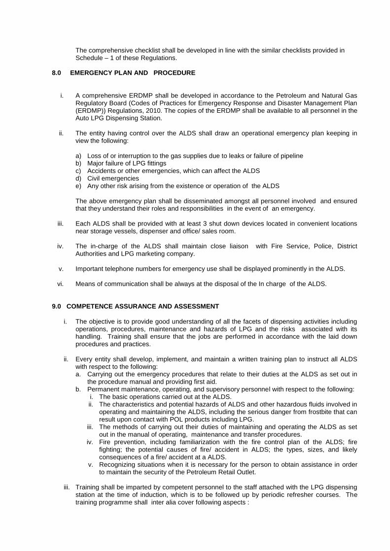
The comprehensive checklist shall be developed in line with the similar checklists provided in Schedule – 1 of these Regulations.
8.0 EMERGENCY PLAN AND PROCEDURE
i. A comprehensive ERDMP shall be developed in accordance to the Petroleum and Natural Gas Regulatory Board (Codes of Practices for Emergency Response and Disaster Management Plan (ERDMP)) Regulations, 2010. The copies of the ERDMP shall be available to all personnel in the Auto LPG Dispensing Station.
ii. The entity having control over the ALDS shall draw an operational emergency plan keeping in view the following:
a) Loss of or interruption to the gas supplies due to leaks or failure of pipeline b) Major failure of LPG fittings c) Accidents or other emergencies, which can affect the ALDS d) Civil emergencies e) Any other risk arising from the existence or operation of the ALDS
The above emergency plan shall be disseminated amongst all personnel involved and ensured that they understand their roles and responsibilities in the event of an emergency.
iii. Each ALDS shall be provided with at least 3 shut down devices located in convenient locations near storage vessels, dispenser and office/ sales room.
iv. The in-charge of the ALDS shall maintain close liaison with Fire Service, Police, District Authorities and LPG marketing company.
v. Important telephone numbers for emergency use shall be displayed prominently in the ALDS. vi. Means of communication shall be always at the disposal of the In charge of the ALDS.
9.0 COMPETENCE ASSURANCE AND ASSESSMENT
i. The objective is to provide good understanding of all the facets of dispensing activities including operations, procedures, maintenance and hazards of LPG and the risks associated with its handling. Training shall ensure that the jobs are performed in accordance with the laid down procedures and practices.
ii. Every entity shall develop, implement, and maintain a written training plan to instruct all ALDS with respect to the following: a. Carrying out the emergency procedures that relate to their duties at the ALDS as set out in
the procedure manual and providing first aid. b. Permanent maintenance, operating, and supervisory personnel with respect to the following:
i. The basic operations carried out at the ALDS. ii. The characteristics and potential hazards of ALDS and other hazardous fluids involved in
operating and maintaining the ALDS, including the serious danger from frostbite that can result upon contact with POL products including LPG.
iii. The methods of carrying out their duties of maintaining and operating the ALDS as set out in the manual of operating, maintenance and transfer procedures.
iv. Fire prevention, including familiarization with the fire control plan of the ALDS; fire fighting; the potential causes of fire/ accident in ALDS; the types, sizes, and likely consequences of a fire/ accident at a ALDS.
v. Recognizing situations when it is necessary for the person to obtain assistance in order to maintain the security of the Petroleum Retail Outlet.
iii. Training shall be imparted by competent personnel to the staff attached with the LPG dispensing
station at the time of induction, which is to be followed up by periodic refresher courses. The training programme shall inter alia cover following aspects :

a. Hazardous characteristics of LPG. b. Familiarisation with operational procedures & practices. c. Commissioning of new facilities and equipment. d. Hands on experience on operation of equipment. e. Routine checks and maintenance activities of the facilities. iv. Knowledge of emergency and manual shut down systems a. Immediate and effective isolation of any LPG leak. b. Accounting of product c. Safety regulations and accident prevention. d. Fire fighting facilities, its upkeep and operation. e. Evacuation and safe egress of the vehicles in an emergency. f. Housekeeping g. Safety in transportation of LPG. h. First aid. i. Emergency plan./drills
iv. Proper records for the training and refresher courses shall be maintained at the installation.
10.0 CUSTOMER SAFETY & AWARENESS 10.1 Display of important information :
At ALDS, the particulars of licence, emergency telephone nos. of local fire service, police, LPG marketing company and emergency instructions shall be conspicuously displayed.
i. Caution boards shall be displayed near the dispenser for customer awareness as below :
a. Stop the engine before refueling b. No smoking c. No flames or pilot lights or use of electrical gadgets d. Avoid contact with liquid LPG e. Do not fill LPG beyond 80 % capacity f. Keep distance from vehicle being fueled.
ii. A display board shall be prominently placed at ALDS for the benefit of the Customer highlighting
behavioral characteristics of LPG in bilingual i.e. Hindi/ English & local language as below :
a. Auto LPG is stored and delivered as a liquid under pressure. b. While changing from liquid to gas, LPG expands approximately 260 times its original volume c. Leakage of liquid LPG is more dangerous than gaseous LPG and it has distinct odour. d. LPG vapour is approximately 1.5 times heavier than air. So, LPG vapour tends to settle
down.
10.2 DOs & DON’Ts DON’Ts i. Do not start the engine / drive away the vehicle till the filling nozzle has been disconnected
from the filler cap of the vehicle. ii. Do not refuel the vehicle during the period LPG is being decanted the storage vessel. iii.
Do not handle LPG without protective hand gloves and safety glasses.
iv.
Do not fill in the Auto LPG Tank which is over due for pressure retesting
DOs
i. Switch off the mobile phone at the ALDS.

ii. Switch off the engine before commencement of refueling of Auto LPG.
iii. Check vehicle tank spout valve and its rubber seal.
iv. Squeeze trigger fully and hold.
v. Ensure a 9 kg DCP Fire Extinguisher is available near the LPG Dispenser
vi. Connect Nozzle – avoid cross threading
vii. In case of any leakage / fire observed, press the ―EMERGENCY STOP ‖ button on the LPG
Dispenser.
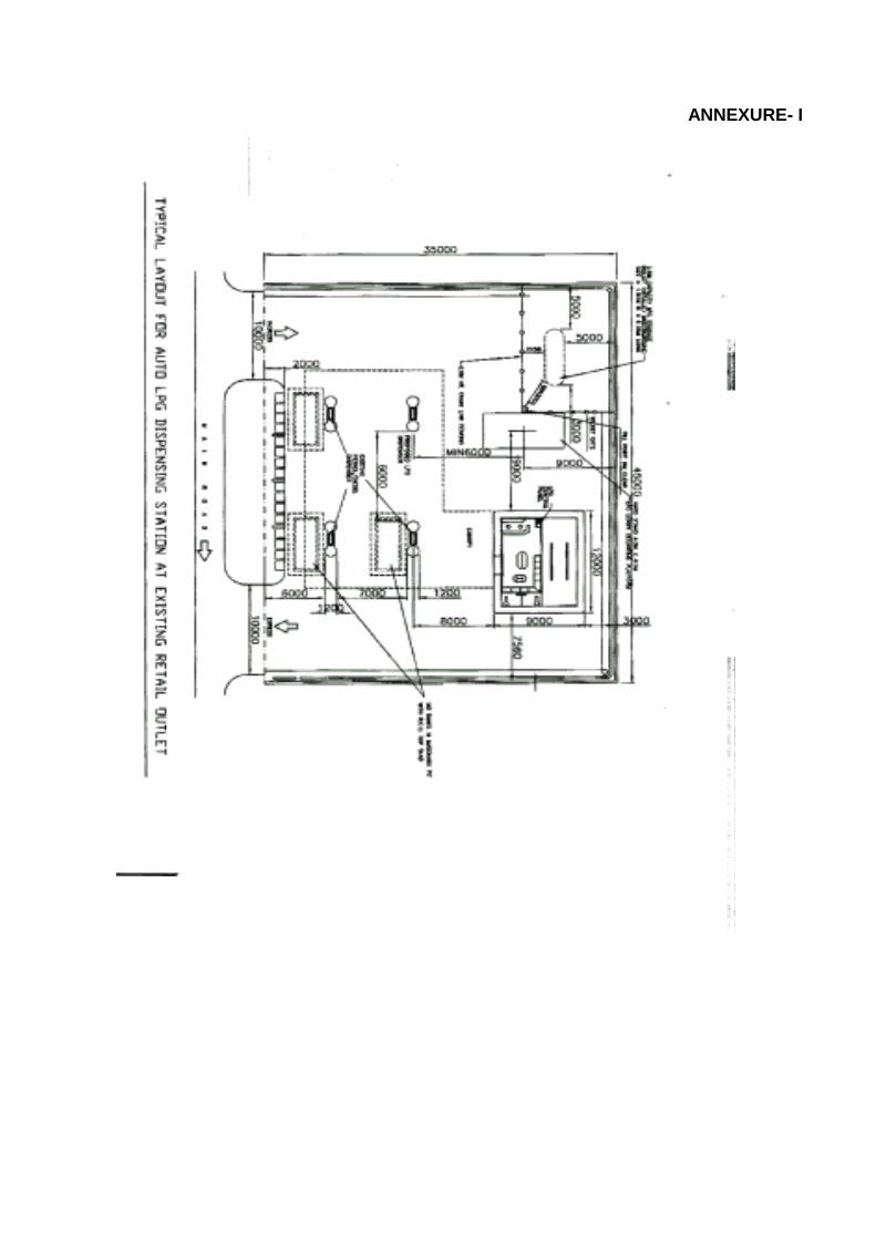
ANNEXURE- I
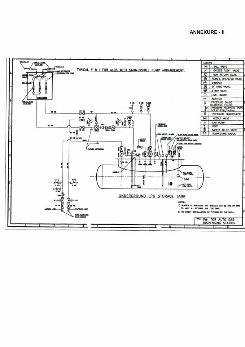
ANNEXURE - II
Annexure - III
INSPECTION OF THE AUTO LPG DISPENSING STATION
S.No ITEMS OBSERVATIONS (State details)
Remarks/ Recommendations
1.0 CHECKLIST 1.1 Bulk Storage Area Condition of earthing of vessels. Functioning of level instruments. Safety valves regularly tested and records
maintained.
Functioning of level gauge and high level alarm. Any sign of leakage/ corrosion. Positioning of fire extinguishers. Fence around storage vessel is 2 m high Conditions, functioning and coverage of sprinkler/
hydrant system.
No simultaneous unloading of LPG and other fuel Illumination level adequate. Condition of cathodic protection system, current ,
potential
Storage area is properly paved No vegetation in the area No unauthorised structure upto the property line Housekeeping. 1.2 Tank lorry unloading Approved spark arrestor fitted with the tanklorries. Proper earthing connections and earth pit
resistance.
Any visible sign of LPG leakage. All flanges completely bolted Only metallic gaskets in use Bolts & nuts protected against corrosion Electrical resistance within limits PESO license for the vehicle. Hose test certificate available 2 nos. of fire extinguishers in the vehicle. Tool kit available First aid box available Flange connections having bonding. Safety instruction booklet / TREM Card available. Wheel choke used while unloading. Portable extinguisher positioned and functional Tank lorry in drive out position Illumination level adequate. Housekeeping in order. 1.3 Dispensing pump
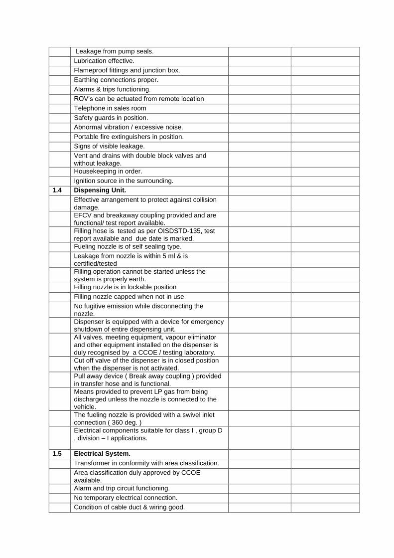
Leakage from pump seals. Lubrication effective. Flameproof fittings and junction box. Earthing connections proper. Alarms & trips functioning. ROV‘s can be actuated from remote location Telephone in sales room Safety guards in position. Abnormal vibration / excessive noise. Portable fire extinguishers in position. Signs of visible leakage. Vent and drains with double block valves and
without leakage.
Housekeeping in order. Ignition source in the surrounding. 1.4 Dispensing Unit. Effective arrangement to protect against collision
damage.
EFCV and breakaway coupling provided and are functional/ test report available.
Filling hose is tested as per OISDSTD-135, test report available and due date is marked.
Fueling nozzle is of self sealing type. Leakage from nozzle is within 5 ml & is
certified/tested
Filling operation cannot be started unless the system is properly earth.
Filling nozzle is in lockable position Filling nozzle capped when not in use No fugitive emission while disconnecting the
nozzle.
Dispenser is equipped with a device for emergency shutdown of entire dispensing unit.
All valves, meeting equipment, vapour eliminator and other equipment installed on the dispenser is duly recognised by a CCOE / testing laboratory.
Cut off valve of the dispenser is in closed position when the dispenser is not activated.
Pull away device ( Break away coupling ) provided in transfer hose and is functional.
Means provided to prevent LP gas from being discharged unless the nozzle is connected to the vehicle.
The fueling nozzle is provided with a swivel inlet connection ( 360 deg. )
Electrical components suitable for class I , group D , division – I applications.
1.5 Electrical System. Transformer in conformity with area classification. Area classification duly approved by CCOE
available.
Alarm and trip circuit functioning. No temporary electrical connection. Condition of cable duct & wiring good.
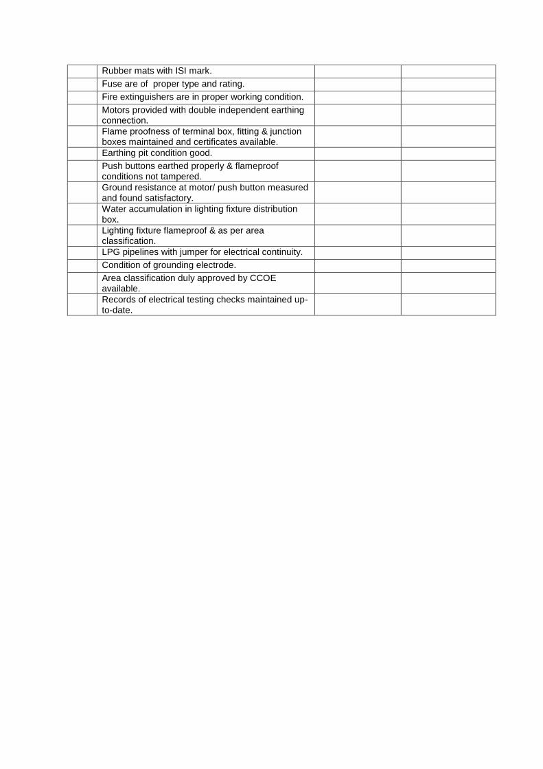
Rubber mats with ISI mark. Fuse are of proper type and rating. Fire extinguishers are in proper working condition. Motors provided with double independent earthing
connection.
Flame proofness of terminal box, fitting & junction boxes maintained and certificates available.
Earthing pit condition good. Push buttons earthed properly & flameproof
conditions not tampered.
Ground resistance at motor/ push button measured and found satisfactory.
Water accumulation in lighting fixture distribution box.
Lighting fixture flameproof & as per area classification.
LPG pipelines with jumper for electrical continuity. Condition of grounding electrode. Area classification duly approved by CCOE
available.
Records of electrical testing checks maintained up-to-date.
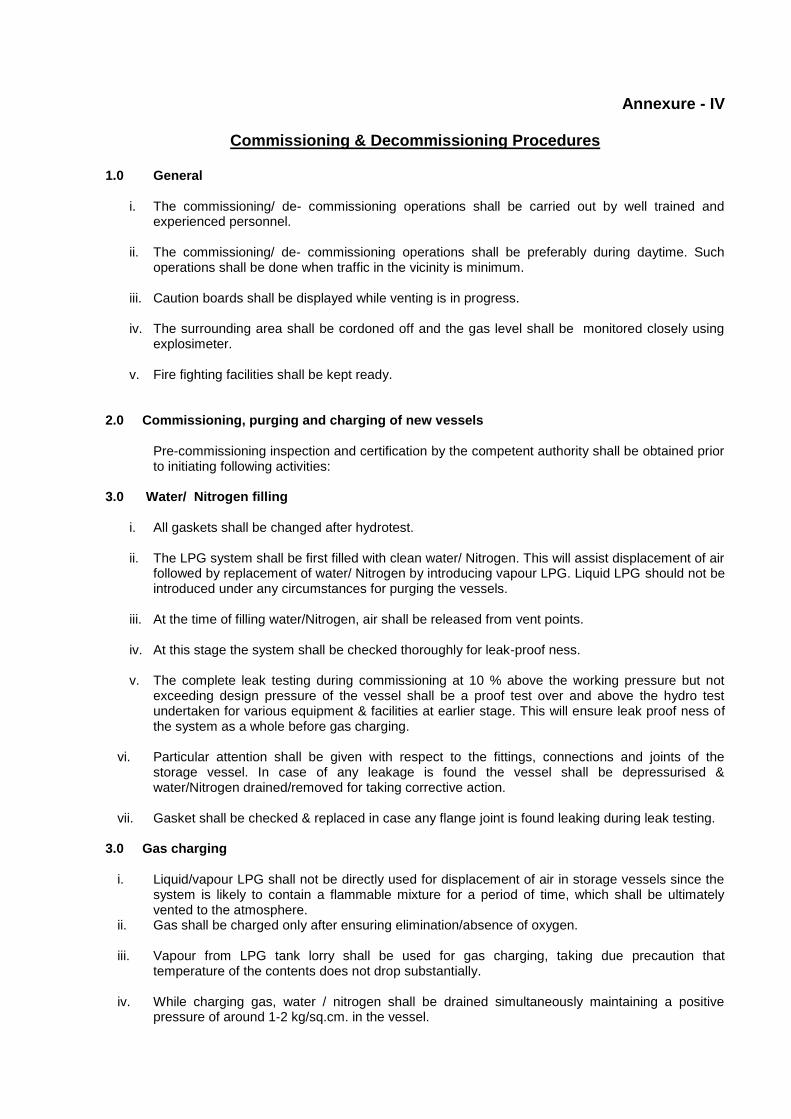
Annexure - IV
Commissioning & Decommissioning Procedures 1.0 General
i. The commissioning/ de- commissioning operations shall be carried out by well trained and experienced personnel.
ii. The commissioning/ de- commissioning operations shall be preferably during daytime. Such
operations shall be done when traffic in the vicinity is minimum.
iii. Caution boards shall be displayed while venting is in progress.
iv. The surrounding area shall be cordoned off and the gas level shall be monitored closely using explosimeter.
v. Fire fighting facilities shall be kept ready.
2.0 Commissioning, purging and charging of new vessels
Pre-commissioning inspection and certification by the competent authority shall be obtained prior to initiating following activities:
3.0 Water/ Nitrogen filling
i. All gaskets shall be changed after hydrotest. ii. The LPG system shall be first filled with clean water/ Nitrogen. This will assist displacement of air
followed by replacement of water/ Nitrogen by introducing vapour LPG. Liquid LPG should not be introduced under any circumstances for purging the vessels.
iii. At the time of filling water/Nitrogen, air shall be released from vent points. iv. At this stage the system shall be checked thoroughly for leak-proof ness.
v. The complete leak testing during commissioning at 10 % above the working pressure but not
exceeding design pressure of the vessel shall be a proof test over and above the hydro test undertaken for various equipment & facilities at earlier stage. This will ensure leak proof ness of the system as a whole before gas charging.
vi. Particular attention shall be given with respect to the fittings, connections and joints of the
storage vessel. In case of any leakage is found the vessel shall be depressurised & water/Nitrogen drained/removed for taking corrective action.
vii. Gasket shall be checked & replaced in case any flange joint is found leaking during leak testing.
3.0 Gas charging
i. Liquid/vapour LPG shall not be directly used for displacement of air in storage vessels since the system is likely to contain a flammable mixture for a period of time, which shall be ultimately vented to the atmosphere.
ii. Gas shall be charged only after ensuring elimination/absence of oxygen.
iii. Vapour from LPG tank lorry shall be used for gas charging, taking due precaution that temperature of the contents does not drop substantially.
iv. While charging gas, water / nitrogen shall be drained simultaneously maintaining a positive
pressure of around 1-2 kg/sq.cm. in the vessel.

v. Pressure in the storage system shall be monitored and creation of vacuum condition to be
prevented.
vi. At the time of draining of water it shall be ensured that no pockets of water remain in the system.
vii. Where water draining is resorted to, by opening of end flanges of headers/lines, such flanges shall be blinded at the end of draining operation.
viii. In case of displacement of Nitrogen with LPG vapour, constant readings of LPG air mixture
should be taken with Explosimeter to ascertain the displacement of Nitrogen with LPG vapours.
ix. Functioning of the level gauges, high level alarm and their correctness shall be checked at the time of water filling and gas charging.
x. Provision shall be made for proper drainage of water from vessels, pipe lines and equipment. In
case of Nitrogen displacement controlled venting should be done from pipelines and equipment to ascertain Nitrogen displacement with LPG. Explosimeter reading shall also be taken to check the concentration levels.
4.0 Liquid charging
i. Liquid LPG shall be introduced at a controlled rate after displacement of entire water / Nitrogen with vapour LPG.
ii. The commissioning operations shall be controlled and supervised by authorised personnel.
iii. Fire fighting system shall be kept in readiness.
5.0 Commissioning of Dispensing unit
i. For commissioning of dispenser unit, liquid LPG shall not be charged and displacement of air shall be carried out by introducing vapour LPG from the storage vessel and venting under controlled conditions with due safety precautions.
ii. Water charging during pressure testing shall be limited up to the inlet of the dispenser so that
internals appurtenances, instruments, metering element and all other accessories are not affected. However, there are no restrictions if Nitrogen is used for purging.
iii. Manufacturer‘s recommendations shall be followed while commissioning the dispensing unit.
6.0 Decommissioning & Gas Freeing of Storage Tanks
i. Water/Nitrogen shall be used for gas freeing adopting procedures similar to water/Nitrogen filling and gas charging during commissioning.
ii. For decommissioning of storage vessels, liquid shall be first exhausted using pumps or
compressors followed by displacement of gas by water/Nitrogen.
iii. The liquid LPG can be transferred to the adjacent tank or a road tanker.
iv. In case compressor is available, pressure in the system shall be reduced by recovering vapour from the storage vessel and transferring to another vessel if the layout of the system so permits.
v. While introducing water/Nitrogen, residual vapour in the storage vessel shall be released at
controlled rate by venting through cold flare.
vi. Check the vessel is gas free with explosimeter

Annexure – V
REFERENCES
i. Regulation for LPG Service and Road Tank Trucks in the Netherland, 1987
ii. Code of Practice 11 : Recommendations for the safe handling of LPG used as an internal combustion engine fuel for motor vehicles (LPG ITA)
iii. AS/NZS 1596:1997 : Storage of Handling of LP Gas iv. AIS 026 D1 : The use of LPG Fuel in Internal Combustion Engine to Power 4-
Wheeled Vehicles v. IS:2825 : Code for Unfired Pressure Vessels vi. IS:5571 : Guide for Selection of Electrical Equipment for Hazardous Area. vii. IS:5572 : Classification of Hazardous Areas (other than mines) having Flammable
Gases & Vapours for Electrical Installations. viii. IS:14861 : BIS Specification of LPG for automotive purposes ix. IS:14899 Liquefied Petroleum Gas containers for automotive use - Specification
x. The Static and Mobile Pressure Vessels (Unfired) Rules-1981 xi. LPG (Regulation of use in Motor Vehicles) Order 2001 xii. Gas Cylinder Rules, 2004 xiii. API Standard 25 – Design and Construction of LP Gas Installations xiv. ASME Boiler and Pressure Vessel Code Sect.VIII Division 1 American Society of Mech.Engrs.,
New York xv. NFPA 58 : Storage and Handling of Liquefied Petroleum Gases xvi. NEPA 59 : LP Gases at Utility Gas Plants xvii. ASME B - 31.3 : Chemical Plant and Petroleum Refinery Piping xviii. PD-5500 : Specification for unfired fusion welded pressure vessels
Schedule 3 : “Storage, Handling and Dispensing at CNG
Dispensing Stations”
Schedule 3 : “Storage, Handling and Dispensing at CNG
Dispensing Stations”
CONTENTS
----------------------------------------------------------------------------------------------------------------------------- ---- S.NO. DESCRIPTION
----------------------------------------------------------------------------------------------------------------------------- ----
1.0 SCOPE
2.0 DEFINITIONS
3.0 NATURAL GAS QUALITY FOR CNG FACILITIES
4.0 FACILITY PLANNING
5.0 CNG STORAGE SYSTEM (Static)
6.0 CNG STORAGE SYSTEM (Mobile)
7.0 CYLINDERS
8.0 CNG PIPING / TUBING
9.0 CNG HOSES
10.0 PRESSURE GAUGES
11.0 COMPRESSOR STATION
12.0 PRESSURE RELIEF DEVICE
13.0 ELECTRICAL EQUIPMENT
14.0 SAFETY AT VEHICLE FOR REFUELLING
15.0 DISPENSING UNIT
16.0 CNG REFUELLING INTO VEHICLES
17.0 FIRE PROTECTION
18.0 EMERGENCY PLAN AND PROCEDURE
19.0 COMPETENCE ASSURANCE AND ASSESSMENT
20.0 AUTOMATION
21.0 SAFETY INSPECTIONS / AUDIT ------------------------------------------------------------------------------------------------------------
ANNEXURES
I References
1.0 SCOPE
This technical standard and specifications including safety standards lays down the minimum requirements in design, operation, inspection, maintenance, training, consumer safety at Petroleum Retail Outlets (PRO). It does not cover the certification or fitness requirements of vehicles.
2.0 DEFINITIONS
a. ―Bulk Storage‖ means a facility for storing CNG in stationary and mobile storages exceeding the capacity of 1000 Lt. These pressure vessels shall conform to the ―Static & Mobile Pressure Vessels (Unfired) Rules, 1981 as amended.
b. ―Cascade (Gas Storage Unit -Bundles of cylinders, Multi-Element Gas Cylinders-MEGCs, Tube Modules or Skids)‖ means a group of gas cylinders interconnected by high-pressure tubing to form a single gas storage unit referred as cascade hereafter. The cascade is also used for transportation of CNG in the structural frame work having facility for lifting and placement.
c. ―Cascade Storage Unit Isolation Valve‖ means a quick action valve for stopping gas flow from a
gas storage unit.
d. ―Compressed Natural Gas (CNG)‖ means mixtures of hydrocarbon gases and vapours, consisting mainly of Methane in gaseous form which has been compressed for use as automotive fuel conforming to IS: 15958 / IS: 15320:2012.
e. ―Cylinder Appurtenances‖ means devices connected to cylinder for safety, control or operating
purposes.
f. ―Cylinder‖ means any closed container having capacity exceeding 500 ml but not exceeding 1000 lts., constructed as per IS 7285-1, IS 7285-2, ISO 11119-1, ISO 11119-2, ISO 11119-3, ISO 11120, EN 12245, EN 12247 or other international standards having approval from statutory authority under Gas Cylinders Rules. These may be of varied capacities to suit vehicles and storage systems. Water capacity of cylinders used for storage of CNG, may exceed 1000 litres up to 2500 litres provided the diameter of such cylinder does not exceed 60 cm.
g. ―CNG ―Mother‖ Station‖ means CNG facility connected to natural gas pipeline and having a
compressor meant primarily to fill mobile cascades. Such facilities, in addition to act as ‗mother‘ station can also fill stationary cascades for CNG dispensing into vehicles.
h. ―CNG ―On line‖ Station‖ means CNG facility connected with natural gas pipeline and having a
compressor primarily to fill stationary cascades for dispensing CNG to vehicles. In case the ‗on line‘ station has enough space to accommodate mobile cascades filling, it can be used to act as mother compressor station.
i. ―CNG daughter station‖ means CNG facility not connected to natural gas pipeline and dispensing
CNG to the vehicles (s) through mobile cascades.
j. ―CNG daughter booster Station‖ means CNG facility not connected to natural gas pipeline and dispensing CNG to the vehicle (s) through CNG booster compressor and mobile cascade.
k. ―Emergency Shut Off Valve‖ means a quick action shut off valve, which operates from full open
to full closed condition in less than one complete turn.
l. ―Fire Resistance Rating (FRR)‖ means the minimum period of time for which all sides of an element of structure, any of which is subjected to a standard fire, continues to perform its structural function and does not permit the spread of fire. Where a period of time is used in conjunction with the abbreviation FRR it is required that the element of structure referred to shall have a fire resistance rating of not less than the period stated in accordance with IS 1642:1989.

m. ―Manifold‖ means the assembly of piping / tubing and fittings used for interconnecting all
cylinders/ vessels to a common pipeline.
n. ―Point of Transfer‖ means the point where the filling/fuelling connection is made, to vessel(s)/ vehicle (s).
o. ―Pressure Relief Device‖ means device designed to prevent rupture of vessel / container by
releasing excessive pressure build-up.
p. ―Set Pressure‖ means the valve opening pressure in a relief valve which shall not exceed the marked service pressure.
q. ―Transportation unit‖ means a cascade/ bulk storage mounted and installed on a Light/ Heavy
Commercial Vehicle, trailer, or semi trailer for movement of CNG on road and governed by statutory regulations.
r. ―Trailer‖ means a trailer or semi-trailer motor vehicle designed specifically for the transportation
of Cylinder bundles with its associated structural framework.
s. ―Maximum Working Pressure‖ means the pressure for which the equipment was fabricated / manufactured or if conditions have changed, the maximum permitted pressure at specified design temperatures.
t. ―Vehicle Refuelling Probe‖ means a CNG refuelling device fitted at the end of the refuelling hose
at the dispenser units.
u. ―Vehicle Refuelling Shut Off Valve‖ means a quick action valve for stopping gas flow and having the facility for venting residual high pressure gas in the refuelling line after completion of the vehicle refuelling operation.
3.0 NATURAL GAS QUALITY FOR CNG FACILITIES 3.1 Quality of Compressed Natural Gas (CNG) for Automotive purposes is governed by IS:15958.
3.2 ODOURISATION 3.2.1 Natural gas introduced into any system covered by this standard should have a distinctive odour
strong enough to detect its presence down to a concentration (of CNG) in air not exceeding 20% of the lower limit of flammability. To achieve this, the injection of odorizing agent shall be done in a quantity to ensure perception of CNG leakage by smell as per IS:15319
3.2.2 Suitable type of filters shall be used for limiting liquid particulate as mentioned in the clause
5.2.1. 3.2.3 In case the natural gas is not odourised, the odorisation and filtration system shall be located in a
separate working area from the compressor or CNG storage unit but within the same fencing. There should be a clear safety distance of 1.5 M around the odorisation and filtration system to facilitate easy maintenance and personnel movement.
3.2.4 The odorisation pumping as well as filtration system shall have 100% stand-by capacity. 4.0 FACILITY PLANNING 4.1 The CNG Refuelling system shall comprise of a gas compression apparatus, static/ mobile
cascade/ pressure vessel and a gas dispenser incorporating a measuring device. The CNG station can also have an air compressor and an air dryer system for actuation of valves. The system shall be `ON-LINE' mother refuelling or daughter dispensing system attached to a mobile cascade.
The systems and components of CNG facility(ies) shall be certified for CNG use and marked accordingly by applicable statutory authority or the agency authorized by them .
4.2 LAYOUT AND INTERDISTANCES 4.2.1 Inter-distances between various equipment, storage cylinders/ cascade etc. shall be as per Table -
I, II. 4.2.2 Safety distances not indicated above should be as approved by Chief Controller of Explosives on
case to case basis after due consideration of all influencing factors. 4.2.3 When inside a MS-HSD Service Station, the CNG storage and dispensing facilities shall be located
in an isolated area not interfering in the vehicular movement on the drive way and not coming within the hazardous areas of petroleum facilities as prescribed in the Fourth schedule of the Petroleum Rules, 2002. The CNG facilities shall not be located beneath bare electric power lines or where exposed by their failure.
4.2.4 The compressor fencing may be limited to avoid obstruction in the driveway if the required clear
space is available thereafter within the service station premises. The dispensing unit may also be located farther from the fence enclosure on a separate pedestal observing the minimum safety clearance mentioned in Table II.
4.2.5 CNG Compressors / Storage units installations shall be permitted to use alternate equipment
locations (e.g. when installed on the top of the RCC canopy) with validation by a qualified engineer(s) with proven expertise in mechanical systems, structural system, electrical systems, gaseous storage systems, fire protection, and gas detection. If compressor is installed on the top of the canopy, installation of cascades above such compressor shall not be permitted. The validation shall at a minimum include the following:
i. Process safety analysis and hazard and operability studies (HAZOPS)
ii. Mitigating fire protection measures such as suppression system as per NFPA-17. Further, if compressor is mounted inside soundproof canopy/ enclosure automatic CO2 flooding system as per NFPA-12 shall be provided.
iii. (3) Fire and gas detection systems designed to interface with an emergency shutdown device
(ESD)
iv. The structure supporting such installations shall meet 4 Hr Fire rating in line with IS 1642:1989-Code of practice for fire safety of buildings.
v. IS 875- Part 1 to 5 (1987): Code of Practice for Design Loads (Other than Earthquake) for
Buildings and Structures including for movable and immovable loads, vibrations at partial / full loading conditions of the CNG compressor.
vi. The structure, Foundation shall be designed for the seismic zone as per IS 1893 (Part 1) 2002 for
Seismic loads.
vii. Alternate Emergency escape routes shall be provided for operating crew in case the equipment is installed at Top of the canopy / elevated platform.
viii. Protective hand railings shall be provided on such elevated roof top‘s / elevated platforms to
prevent accidental fall of operating crew.
ix. Weather protection from sun & rain (ventilated canopy) shall be provided for cascades.
x. Emergency shut down (ESD) system shall be provided: This device, when activated, shall shut off the power supply to the compressor and gas supply to the dispenser immediately.
xi. An emergency manual shutdown device shall be provided within 3.0 m of the dispensing area and also at a suitable remote manned location.
xii. Control circuits shall be arranged so that, when an emergency shutdown device is activated or
electric power is cut off, systems that shut down remain off until manually activated or reset after a safe condition is restored.
xiii. The main stairs for accessing such elevated platform shall be minimum 1.2 m wide.
4.2.6 Provisions related to Convenience store / ATM / office cabin:
a. The items to be sold from a Convenience Store (C-Store) in a retail outlet shall be decided keeping in view hazards associated with the items being stocked and sold. Open flame appliances shall not be used in the retail outlet.
b. Provision for car parking shall be made in retail outlet with C- Store @ one slot distinctly marked for each 25 sq metre of C-Store area.
c. Separate pathways outside dispensing area shall be provided for movement of customers for C-Store.
d. The CNG dispensers shall maintain a minimum distance of 4 mts from any above ground structure/ property boundary.
e. Any building or room intended to serve as a control point for a retail outlet shall preferably be so located that an attendant in the sales room can see the forecourt and dispensing area clearly.
TABLE - I
INTER DISTANCES
FROM BUILDINGS AND OUTER BOUNDARIES TO GAS STORAGE UNITS
Total capacity Min. distance from of gas storage units Buildings and boundaries (In litres) (In Meters)
(1) (2)
upto 4500 2.5
4500 to 10000 4.0
10000 to 100000 10.0
Note : 1. If on the side (s) towards the boundary of the installation, the clearance as above is not available, the same may be reduced to 2 meters provided a 4 H-FRR (As per IS 1642 (1989)) RCC wall of adequate height and length covering the cylinder cascades is constructed at the boundary and adequate clear space is available on the other side of the wall.
2. If Multiple cascades are located maintaining inter-distance of minimum 1 m then the required safety distances shall be considered as applicable in case of the water capacity of the higher capacity individual cascade.

TABLE - II INTER DISTANCES BETWEEN VARIOUS FACILITIES OF NATURAL GAS HANDLING AT INSTALLATION
Distance from - In metres
1 2 3 4 5 6 7
CNG Compressor
CNG Dispensing Unit
Storage Cascade
Outer boundary wall/ Chain link fencing
MS/HSD dispenser
Vent of MS/HSD u/g Storage tanks
Filling point of MS/HSD
1 CNG Compressor
- 3 2 3 6 6 T1 (Min-3)
2 CNG Dispensing Unit
3 - 2 4 6 4 -do-
3 Storage Cascade
2 2 - T1 T1 (min-6)
T1 (Min-4)
-do-
4 Outer boundary wall/ Chain link fencing
3 4 T1 - 6 4 -do-
5 MS/HSD dispenser
6 6 T1 (Min-6)
6 - 6 -do-
6 Vent of
MS/HSD u/g Storage tanks
6 4 T1 (Min-4)
4 6 - 6
7 Filling point of MS/HSD
T1 (Min-3)
T1 (Min-3)
T1 (Min-3)
T1 (Min-3)
T1 (Min-3)
6 *
NOTES : i) T-I denotes Table-I ii) Distances shown as ―– ‖ shall be any distance necessary for operational convenience. iii) A suitable curbing platform shall be provided at the base of the dispensing unit to prevent
vehicles from coming too near the unit. iv) A CNG cascade having cylinders of total water capacity not exceeding 4500 liters can be
mounted on top of the compressor super structure. The assembly shall observe 3-meter clearance around and also from the dispensing unit. This can be reduced to 2 meter as per Note- I of Table – I.
v) * As per Schedule – 1 of these regulations
5.0 CNG STORAGE SYSTEM (Static) 5.1 The cascade having horizontal cylinders and sited parallel to other cascade, cylinder fittings
should be arranged so that they do not face cylinder fittings of other cascade.
5.2 Cylinder installed horizontally in a cascade shall be separated from another cylinder in the
cascade by a distance of minimum 20mm. 5.3 Cascade with horizontal cylinders shall have the valves fitted on the same side within the
cascade opposite to the refuelling point and arranged in a manner that any gas leakage is discharged upwards.
5.4 Cascade/bulk units shall be installed on a firm, compacted, well-drained non-combustible
foundation. This foundation may be in the form of a plinth with the raised edge at 2 M from the front and sides of the cascade forming a kerb upto which vehicles should be permitted. The cascade shall be securely anchored to prevent floating in case flooding is anticipated.
5.5 Gas storage facility shall be protected from the effects of the weather by a roof or canopy
designed to facilitate the dispersion of free or escaped gas. 5.6 Adequate means shall be provided to prevent the flow or accumulation of flammable or
combustible liquids under containers such as by grading, pads or diversion curbs. 5.7 Clause 6.5 subclause iv, v, vi, viii, ix and x shall also be applicable for static CNG storage
system. 5.8 Cascade storage on the top of the roof shall be permitted on first floor. There shall not be
any further construction / inhabitation above this storage. 6.0 CNG STORAGE SYSTEM (Mobile) 6.1 Only dedicated trailer, truck or any other vehicle to be used for transportation of CNG
storage units. These units should have lugs fitted for lifting and in no case magnetic device to be used for lifting purposes.
6.2 The vehicle with the cascade thereon, shall be placed with easy access and egress on a low
platform or hard compacted ground, which shall extend to atleast another one meter on all sides and this platform or hard ground shall be under a light roof or canopy as described in 5.5 above.
6.3 For other inter-distances refer Table I, II, above. 6.4 The trailers/ vehicle carrying CNG should be made immovable by application of brake and
wheel choke prior to initiation of filling or dispensing operation. 6.5 Whether attached to a trailer or mounted on a vehicle chassis frame the Cascade shall be
designed to meet the following : i. The Cylinders in a cascade must be structurally supported and held together as a unit and
secured in a manner that prevents movement in relation to the structural assembly and movement that would result in the concentration of harmful local stresses. The frame design must ensure stability under normal operating conditions.
ii. The frame must securely retain all the components of the bundle and must protect them
from damage during conditions normally incident to transportation. The method of cylinder restraint must prevent any vertical or horizontal movement or rotation of the cylinder that could cause undue strain on the manifold or cylinder shell. The total assembly must be able to withstand rough handling, including being dropped or overturned. (Refer CGA TB 25 Design Considerations For Tube Trailers / Tube Modules)
iii. The frame must include features designed for the handling and transportation of the bundle. iv. The frame structural members must be designed for a vertical load of 2 times the maximum
gross weight of the bundle. Design stress levels shall not exceed is as per IS 800.
v. The frame must not contain any protrusions from the exterior frame structure that could cause a hazardous condition.
vi. The frame design must prevent collection of water or other debris that would increase the
tare weight of bundles filled by weight. vii. The floor of the bundle frame must not buckle during normal operating conditions. viii. Each new Cascade design beyond 4500 litre water capacity must have a design approval
certificate. The manufacturer shall obtain approval of a new design along with the Copies of all engineering drawings, calculations, and test data necessary to ensure that the design meets the relevant specification from a firm of repute e.g FM / UL .
ix. The cylinders shall be manufactured as per IS 7285-1, IS 7285-2, ISO 11119-1, ISO 11119-
2, ISO 11119-3, ISO 11120, EN 12245, EN 12247. x. Individual Cascade shall have all cylinders of a particular make, type and capacity. All
cylinders in a cascade shall conform to a single design code (mentioned above in para (8.5 ix)).
xi. Seamless cylinders longer than 2 m (6.5 feet) shall be mounted horizontally for
transportation on a motor vehicle or in an ISO framework or other framework of equivalent structural integrity in accordance with CGA TB–25
xii. Refer ISO 6346 for the dimensions of ISO framework for transportation.
7.0 CYLINDERS 7.1 The cylinders and their fittings for CNG use shall be designed, manufactured, tested
including hydrostatic stretch test at a pressure in full conformity to IS 7285-1, IS 7285-2, ISO 11119-1, ISO 11119-2, ISO 11119-3, ISO 11120, EN 12245, EN 12247 or other national / international standards having approval from statutory authority under Gas Cylinder Rules 2004 ie Chief Controller of Explosives considering the maximum allowable operating pressure of 250 bar.
7.2 These cylinders are to be permanently and clearly marked for ―CNG only‖ and also labelled
"CNG ONLY" in letter at least 25 mm high in contrasting colour in a location which shall be visible after installation.
7.3 The cylinder shall be fabricated from steel / composite materials as per the national /
international design codes referred above in cl 9.1 any other standard duly approved by the Chief Controller of Explosives.
7.4 The cylinders shall be re-examined / re-tested every three years and in accordance with Gas
Cylinder Rules, 2004 by a competent person in line with the directives of the Chief Controller of Explosives with due markings. No cylinder shall be used which has not been duly re-tested as indicated.
7.5 Cylinders shall be painted white to reduce solar heating effect and protect it from
atmospheric corrosion. 8.0 CNG PIPING / TUBING 8.1 All rigid piping, tubing, fittings and other piping components shall conform to the
recommendations of ANSI B 31.3. All the elements of piping should be designed for the full range of pressures, temperatures and loading to which they may be subjected with a factor of safety of at least 4 based on the minimum specified tensile strength at 20 deg. C.
8.2 Gaskets, packing and any other materials used shall be compatible with natural gas and its
service conditions.
8.3 All the piping and tubing shall have minimum turns with adequate provision for expansion, contraction, jarring, vibration and settling. Exterior piping may be either buried with suitable corrosion protection or installed 30 cm. above the ground level with supports and protection against mechanical and corrosive damage.
8.4 Rigid pipelines shall have welded joints between their respective components. 8.5 All the piping and tubing shall withstand a pressure equal to that of safety relief device and
tested accordingly after assembly. The testing to be done by inert gas, in case natural gas is used the suitable safety measures to be adhered to.
8.6 The fuel lines shall have a positive segregation with electrical cables. 8.6 VALVES
8.6.1 A minimum of four shut off valves shall be fitted between the gas storage unit and vehicle refuelling filling nozzle as explained below:
a. Each CNG storage unit to have quick action isolation valve in the steel supply pipe
immediately adjacent to such storage unit to enable isolation of individual storage unit. These valves shall be within fencing of storage unit.
b. Master shut off valve with locking arrangement in close position, shall be installed in steel outlet pipe outside but immediately adjacent to the gas storage unit to isolate all downstream equipment from the gas storage unit. This valve shall be outside the fencing.
c. A quick action emergency and isolation shut off valve shall be installed near dispensing unit with easy approach and to remain closed when refuelling is not being done.
d. A vehicle refuelling shut off valve shall be installed for each flexible vehicle refuelling hose to control the refuelling operation and shall have venting provision to allow for the bleeding of the residual high pressure gas after refuelling is complete.
8.6.2 All these valves and other elements of piping shall be suitable for the full range of pressure
and temperature to which they may be subjected. These valves are to have permanent marking for service rating etc.
9. 0 CNG HOSES 9.1 Internally braided, electrically continuous, non-metallic and metallic hoses resistant to
corrosion and suitable to the natural gas service shall be used for CNG service in the downstream of emergency and isolation shut off valve.
9.2 These flexible hoses and their connections shall be suitable for most severe pressure and
temperature service condition expected with a burst pressure of at least four times the maximum working pressure.
9.3 The flexible hoses with their connections shall be tested after assembly and prior to use to
atleast two times the working pressure and also tested to a pneumatic pressure of atleast 400 bar under water. Thereafter, all the hoses shall be examined visually and tested for leaks with soapsuds or equivalent at an interval not exceeding one year. Hoses shall be rejected and destroyed in the event of any leakage. These tests are to be recorded and such records shall be available at installations at all times.
This shall be done safely in a controlled environment by the trained technicians having
adequate expertise with respect to the assembly of hoses, breakaways, valves and fuel nozzles.
9.4 Flexible hoses shall have permanent marking indicating the manufacturer's name/ identification, working pressure and suitability for use with CNG.
9.5 CNG flexible electrically conductive hose shall be meeting the requirement as per
NFPA-52 or NGV 4.2 or equivalent. 10. 0 PRESSURE GAUGES 10.1 Every CNG storage unit including each cascade or bulk storage tank shall be provided with
a suitable pressure gauge directly in communication with them. 10.2 The CNG storage unit shall have an opening not to exceed 1.4-mm diameter at the
connection where pressure gauge is mounted. 10.3 The pressure gauge shall have dial graduated to read approximately double the operating
pressure but in no case less than 1.2 times the pressure at which pressure relief valve is set to function.
10.4 All pressure gauges in the installation shall be tested and calibrated atleast once a year and
records maintained. 11. 0 COMPRESSOR STATION 11.1 The piping and its fittings upto the battery limit of CNG installation shall conform to ASME B
31.8 or equivalent. 11.2 Compressor shall be designed for use in CNG service and for the pressures and
temperature to which it may be subjected under normal operating conditions conforming to API 618/ API 813 / API 11 P or equivalent standard and Flame proof electric motor and associated fittings should conform to IS/IEC 60079 suitable for Gas Group IIA as applicable for Natural Gas.
11.3 Compressor shall be fitted with the following minimum devices :
a. Pressure relief valves on inlet and all stages to prevent pressure build up above the predetermined set point.
b. High discharge temperature shut down c. High cooling water temperature switch fitted to cooling water return line to shut the
compressor in the event of a fault. d. High, inlet, inter stage & discharge pressures shut down. e. Low lube oil pressure shut down f. Low cooling water flow switch fitted to the cooling water return line to shut the
compressor in the event of fault. g. A remote isolation switch for emergency shut down to be provided with manual reset at
control panel. 11.4 Compressor shall be provided atleast the following clear and permanent markings readily
accessible and easy to read in the installed position :
a. Manufacturer's name b. Model c. Serial No./ month & year of manufacture d. Certificate of approval no. e. Rated capacity (cubic meter per hour) f. Operating speed (RPM) g. Required driving power( in kW) h. Maximum & minimum supply pressures i. Maximum outlet pressure j. Certification for Natural Gas use

11.5 A compressor and its all fittings shall be tested for compliance of relevant standard suitable for CNG use by a qualified engineer.
12. 0 PRESSURE RELIEF DEVICE 12.1 Safety Relief Devices may consist of either burst disc or safety relief valve and should
conform to the requirements of API 520 or equivalent equipment design standards. 12.2 Safety relief devices shall be installed with unobstructed full size discharge to a safe place
on bulk tanks and cylinders in the vertical position with suitable rain caps. These devices should have their outlet arranged in a manner so that in case of emergency a high-pressure gas escapes from these should not directly hit on operators/ persons in the close vicinity.
12.3 Cylinder should have safety relief devices fitted in conformity to the Gas Cylinder Rules. 12.4 Piping shall be protected by safety relief devices in conformity to design standards. 12.5 Safety relief valves shall have a locking arrangement to prevent tampering by unauthorised
persons. Any adjustments to the safety relief valve shall be made by manufacturer or a competent person. These valves should have a permanent tag indicating pressure setting, date of re-setting/ setting and capacity.
12.6 All safety relief devices shall be tested at least once a year for proper operations and
records to be maintained. 12.7 All the safety relief devices shall have manufacturer's permanent marking indicating
following:
a. Set pressure to start discharge b. Discharge capacity in CuM / min.
12.8 No shut off valves shall be installed between the safety relief device and the gas storage unit
or bulk tank. 12..9 All natural gas devices not otherwise specifically mentioned shall be constructed and
installed to provide a safety equivalent to that other parts of the system. 12.10 Gas detectors interlocked with compressor cut out switch in the electrical system of the
compressor are to be installed which would automatically switch off the unit in case of major gas leak.
13.0 ELECTRICAL EQUIPMENT
13.1 All electrical wiring and equipment, gas storage dispensing unit located in hazardous area
Division I and II shall be in accordance with the Indian Electricity Rules, Gas Cylinder Rules, IS:5571, IS:5572 , NFPA - 52.
13.2 The earthing at the installation, protection against ignition arising out of static, lightning and
stray currents shall be as per Indian Electricity Rules. 13.3 The electrical power distribution system shall be as per clause 4.0 of Schedule – 1 of these
Regulations. 14.0 SAFETY AT VEHICLE FOR REFUELLING 14.1 The vehicles shall have approved type of CNG kit fitted in accordance with the guidelines of
Ministry of Surface Transport, Govt. of India by an authorised workshop and such workshop should issue a fitness certificate to the vehicle for its suitability for CNG use. Such certificate should be always carried by the driver of the vehicle at all times.
14.2 Driver of the vehicle should also carry the record showing the last examination of the vital parts of the system fitted in the vehicle for CNG use and their next due date for such examination. The details must include the test periodicity of cylinder, pressure relief devices, pressure gauges, piping etc.
14.3 The cylinder with valves and connected facilities fitted in the vehicle shall be in accordance
with Gas Cylinder Rules. These cylinders should be subjected to hydraulic test at least once every three years.
14.4 Every vehicle using CNG fuel system should display ―CNG‖ labels prominently in compliance
to Central Motor Vehicle Rules. 14.5 Manufacturing of Type-1 & Type 2 Nozzles shall be in accordance with NGV1 & ISO14469-2
standards. 15.0 DISPENSING UNIT 15.1 Dispensers shall be installed on a suitable foundation observing the minimum safety distances
etc. as given in 6.0 above. Dispensing unit to be protected against possible damage by vehicular movement. Dispenser mounting and installation shall be in accordance with NFPA 52 and NFPA30A or as per design standard.
15.2 The flexible hoses fitted on the dispenser shall be mechanically and electrically continuous.
The design, material and construction of hoses shall be suitable for CNG and shall withstand not less than four times the maximum working pressure of the system.
15.3 The dispensing unit shall be of a type approved by the Chief Controller of Explosives /
Statutory Authorities . 15.4 Dispensing unit shall be suitable for use of CNG in accordance with NGV 4.1, Hoses as per
NGV 4.2 and Breakaway as per NGV 4.4. 16. 0 CNG REFUELLING INTO VEHICLES 16.1 The vehicle refuelling shall be done by an experienced operator duly certified by the oil / gas
company having control over the refuelling station. 16.2 The operator of the CNG dispensing unit shall check the following prior to refuelling the gas:
a. The driver of the vehicle is carrying updated history record as given in clause 16. b. There is no smoking, naked flame or any other source of ignition within six meter of the
refuelling point. c. There is no leakage in the CNG fuel system reported by the driver of the vehicle. d. The fuel connection is in good condition and matches the dispensers filling nozzle. Fuel
connection shall be tight without any leakage. e. The engine is switched off, hand brake is firmly applied, the vehicle parked in gear or in
"P" with automatic transmission. f. No passenger remains inside the vehicle.
16.3 Detailed precautions (refer 18.2) and procedure of refuelling to be displayed near the
dispensing unit and strictly followed by the operator. 16.4 The operator of the dispensing machine should not leave the vehicle being refuelled. 16.5 The cylinder on the vehicle shall not be charged in excess of maximum allowable working
pressure at normal temperature for the cylinder.
16.6 Before the refuelled vehicle is driven away from the dispensing point the operator and driver
should ensure that there are no apparent gas leaks either on the vehicle or on the dispensing point that may have been caused through faulty filling or the faulty action of connecting or disconnecting.
16.7 Warning signs depicting "STOP VEHICLE", "NO SMOKING", "NO OPEN FLAME
PERMITTED", ―FLAMMABLE GAS", ―NO MOBILE PHONE‖, ―SWITCH OFF THE MOBILE PHONES‖ shall be displayed at dispensing station and compressor areas. The location of the signs shall be such that these are prominently visible from each point of transfer/ operation.
16.8 The operator shall take all measures for ensuring smooth vehicle movement in the outlet
including restriction on number of vehicles near the fill points. 17. 0 FIRE PROTECTION 17.1 Fire fighting facilities need to be carefully planned after considering the availability of
municipal fire tenders etc. However, atleast the following Portable fire extinguishers shall be positioned:
S.No. Location Type of Extinguishers
1 Dispensing Unit 1 x 9 kg. DCP
2 Compressor ( on-line) 1 x 9 kg. DCP
3 Mother station 1x 75 kg DCP
4 CNG Storage 1 x 9 kg. DCP
5 Cascade refuelling area 1 x 9 kg. DCP
6 MCC/ Electrical Installation 1 x 4.5 kg CO2 Per 25 Sq.M floor area
17.2 Any other flammable materials not specified in this standard in the CNG installation shall be
stored in a non-flammable chamber with a minimum safety distance of 15 M from compressor station/ MCC/ electrical installation.
17.3 All approaches to machines, compressors, storage facilities and work places shall be free
from obstacles, so that they are readily accessible in an emergency. 17.4 The electrical installations shall be inspected by an Electrical Inspector as per IE Rules and
compliance shall be made as pointed out in the inspection. Records shall be maintained for all periodic inspections.
17.5 The flameproof characteristics of electrical equipment shall be checked through visual
checks, condition of gasket, completeness and tightness of bolts, glands and as recommended by manufacturer's test certificates.
17.6 No unauthorised additions or modifications of the service station whether temporary or
permanent shall be taken up. 17.7 Proper illumination to be ensured for all operating and non-operating areas. 17.8 All electrical maintenance at the Automotive Station shall be undertaken by licensed
electrical technician under supervision of authorised person. 17.9 Each installation shall have minimum two numbers hand held explosive meter in working
conditions at all times. 17.10 The work permit shall be issued by designated person and be followed. The annexure – vi
(a) and vi (b) of Schedule – 1 shall be followed.
18. 0 EMERGENCY PLAN AND PROCEDURE 18.1 A comprehensive ERDMP shall be developed in accordance to the Petroleum and Natural
Gas Regulatory Board (Codes of Practices for Emergency Response and Disaster Management Plan (ERDMP)) Regulations, 2010. The copies of the ERDMP shall be available to all personnel at the CNG dispensing station.
18.2 The entity having control over the refueling station shall draw an operational emergency
plan in consultation with adjoining establishments and local authorities e.g. fire brigade, police, and other District Emergency Authorities etc. for the following circumstances:
a. Loss of or interruption to the gas supplies due to leaks or failure of pipeline b. Over-odorisation of the gas c. Major failure of CNG fittings d. Accidents or other emergencies, which can affect the CNG refuelling, station e. Civil emergencies f. Any other risk arising from the existence or use of the CNG refuelling station.
18.3 The above emergency plan shall be disseminated amongst all personnel involved and
ensured that they understand their roles and responsibilities in the event of an emergency. 18.4 The operator of the refuelling station should have close liaison with Fire Service, the Police,
the Municipal Authorities and the person supplying gas to CNG facility. 18.5 Important telephone numbers for emergency use shall be displayed prominently. 18.6 Means of communication shall be always at the disposal of the Incharge of the installation
on 24 hours basis. 18.7 The emergency plan should be tested with drill atleast once a year. 19. 0 COMPETENCE ASSURANCE AND ASSESSMENT
19.1 The objective is to provide good understanding of all the facets of dispensing activities
including operations, procedures, maintenance and hazards of CNG and the risks associated with handling of the product. Training shall ensure that the jobs are performed in accordance with the laid down procedures and practices. .
19.2 Every entity shall develop, implement, and maintain a written training plan to instruct all CNG
dispensing station personnel with respect to the following:
19.2.1 Carrying out the emergency procedures that relate to their duties at the CNG dispensing
station as set out in the procedure manual and providing first aid.
19.2.2 Permanent maintenance, operating, and supervisory personnel with respect to the following:
i. The basic operations carried out at the CNG dispensing station
ii. The characteristics and potential hazards of CNG dispensing station and other
hazardous fluids involved in operating and maintaining the CNG dispensing station,
including the serious danger from frostbite that can result upon contact with POL
products and CNG.
iii. The methods of carrying out their duties of maintaining and operatingt as set out in the
manual of operating, maintenance and transfer procedures.
iv. Fire prevention, including familiarization with the fire control plan of the CNG dispensing
station; fire fighting; the potential causes of fire/ accident in CNG dispensing station; the
types, sizes, and likely consequences of a fire/ accident at a CNG dispensing station.
v. Recognizing situations when it is necessary for the person to obtain assistance in order
to maintain the security of the CNG dispensing station.
19.2 Training shall be imparted to the staff attached with the CNG dispensing station at the time of
induction, which is to be followed up by periodic refresher courses once every year. The training programme shall inter alia cover following aspects:
a. Hazardous characteristics of CNG. b. Familiarisation with operational procedures & practices. c. Commissioning of new facilities and equipment. d. Hands on experience on operation of equipment. e. Routine maintenance activities of the facilities. f. Knowledge of emergency and manual shut down systems g. Immediate and effective isolation of any CNG leak. h. Accounting of product i. Safety regulations and accident prevention. j. Fire fighting facilities ,methods of fire fighting and its upkeep. k. Evacuation and safe egress of the vehicles. l. Housekeeping m. Safety in transportation of CNG. n. First aid. o. Emergency plan /drills p. Natural gas leakage possibility and its containment. q. Filling nozzles, types of gasket/ seal etc. r. Access control of vehicles so as to allow the vehicle with tested cylinders to be filled with
CNG 19.3 Appropriate training techniques shall be adopted which will include:
a. Classroom training b. Hands on/ practical training c. Demonstration d. Case studies e. Training aids
19.4 Proper records for the training and refresher courses shall be maintained at the installation.
20.0 Automation
The automation (Forecourt Control) where provided, shall comply with the provisions as specified clause 5.0 of Schedule – 1 of these Regulations.
21.0 SAFETY INSPECTIONS / AUDIT
The safety inspections / audit of CNG dispensing station shall be carried out as given below:
TYPE FREQUEMCY AGENCY
General Inspection Daily Operating personnel
Twice in a quarter Authorised personnel of marketing company
Safety Audit Once in a year Authorised Person
Electrical Audit Once in three years Licensed Electrical agency
The comprehensive checklist shall be developed in line with the similar checklists provided in Schedule – 1 of these Regulations.
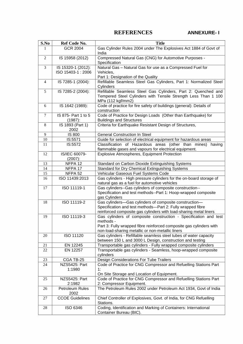
REFERENCES ANNEXURE- I
S.No Ref Code No. Title 1 GCR 2004 Gas Cylinder Rules 2004 under The Explosives Act 1884 of Govt of
India
2 IS 15958 (2012) Compressed Natural Gas (CNG) for Automotive Purposes -Specification
3 IS 15320-1 (2012): ISO 15403-1 : 2006
Natural Gas – Natural Gas for use as a Compressed Fuel for Vehicles, Part 1: Designation of the Quality
4 IS 7285-1 (2004): Refillable Seamless Steel Gas Cylinders, Part 1: Normalized Steel Cylinders
5 IS 7285-2 (2004): Refillable Seamless Steel Gas Cylinders, Part 2: Quenched and Tempered Steel Cylinders with Tensile Strength Less Than 1 100 MPa (112 kgf/mm2)
6 IS 1642 (1989): Code of practice for fire safety of buildings (general): Details of construction
7 IS 875- Part 1 to 5 (1987):
Code of Practice for Design Loads (Other than Earthquake) for Buildings and Structures
8 IS 1893 (Part 1) 2002
Criteria for Earthquake Resistant Design of Structures,
9 IS 800 General Construction In Steel
10 IS:5571 Guide for selection of electrical equipment for hazardous areas
11 IS:5572 Classification of Hazardous areas (other than mines) having flammable gases and vapours for electrical equipment.
12 IS/IEC 60079- (2007):
Explosive Atmospheres, Equipment Protection
13 NFPA 12 Standard on Carbon Dioxide Extinguishing Systems
14 NFPA 17 Standard for Dry Chemical Extinguishing Systems
15 NFPA 52 Vehicular Gaseous Fuel Systems Code
16 ISO 11439:2013 Gas cylinders - High pressure cylinders for the on-board storage of natural gas as a fuel for automotive vehicles
17 ISO 11119-1 Gas cylinders--Gas cylinders of composite construction--Specification and test methods--Part 1: Hoop-wrapped composite gas Cylinders
18 ISO 11119-2 Gas cylinders—Gas cylinders of composite construction—Specification and test methods—Part 2: Fully wrapped fibre reinforced composite gas cylinders with load-sharing metal liners
19 ISO 11119-3 Gas cylinders of composite construction - Specification and test methods - Part 3: Fully wrapped fibre reinforced composite gas cylinders with non-load-sharing metallic or non-metallic liners
20 ISO 11120 Gas cylinders - Refillable seamless steel tubes of water capacity between 150 L and 3000 L Design, construction and testing
21 EN 12245 Transportable gas cylinders - Fully wrapped composite cylinders
22 EN 12257 Transportable gas cylinders - Seamless, hoop-wrapped composite cylinders
23 CGA TB-25 Design Considerations For Tube Trailers
24 NZS5425: Part 1:1980
Code of Practice for CNG Compressor and Refuelling Stations Part 1: On Site Storage and Location of Equipment.
25 NZS5425: Part 2:1982
Code of Practice for CNG Compressor and Refuelling Stations Part 2: Compressor Equipment.
26 Petroleum Rules 2002
The Petroleum Rules 2002 under Petroleum Act 1934, Govt of India
27 CCOE Guidelines Chief Controller of Explosives, Govt. of India, for CNG Refuelling Stations.
28 ISO 6346 Coding, Identification and Marking of Containers: International Container Bureau (BIC).