Embed Size (px)
DESCRIPTION
D9Si4xQzDn2
Citation preview

Release Notes
Version 2012.1
PetroMod
PetroMod petroleum systems modeling software
PetroModPetroModPMPM
2 PetroMod 2012.1
Sch
lum
be
rger P
ub
lic
Copyright Notice
Copyright © 2012 Schlumberger. All rights reserved. No part of this document may be reproduced, stored in a retrieval system, or translated in any form or by any means, electronic or mechanical, including photocopying and recording, without the prior written permission of Schlumberger Information Solutions, 5599 San Felipe, Suite 100, Houston, TX 77056-2722.
Disclaimer
Use of this product is governed by the License Agreement. Schlumberger makes no warranties, express, implied, or statutory, with respect to the product described herein and disclaims without limitation any warranties of merchantability or fitness for a particular purpose. Schlumberger reserves the right to revise the information in this manual at any time without notice.
Trademark Information
*Mark of Schlumberger. Certain other products and product names are trademarks or registered trademarks of their respective companies or organizations.

3 Release Notes
Sch
lum
be
rger P
ub
lic
Contents
About PetroMod ....................................................................................................... 5
New in PetroMod 2012.1 ......................................................................................... 7
PetroMod-LSF (Load Sharing Facility) Integration Kit ......................................... 7
Simulation Cluster Manager (SCM) ...................................................................... 7
PetroMod Command Menu ................................................................................... 7
PetroMod 1D ......................................................................................................... 8
PetroBuilder 3D and PetroBuilder 2D ................................................................... 9
PetroBuilder 3D .................................................................................................. 10
PetroBuilder 2D .................................................................................................. 11
Simulator ............................................................................................................ 12
Kinetics Editor .................................................................................................... 13
Lithology Editor .................................................................................................. 13
Well Editor .......................................................................................................... 13
PetroReport ........................................................................................................ 14
Viewer 2D ........................................................................................................... 15
Viewer 3D ........................................................................................................... 15
Bug Fixes ............................................................................................................... 17
Known Issues ........................................................................................................ 19
All Modules ......................................................................................................... 19
PetroMod 1D ....................................................................................................... 19
PetroBuilder 2D .................................................................................................. 20
PetroBuilder 3D .................................................................................................. 22
Viewer 2D ........................................................................................................... 23
Viewer 3D ........................................................................................................... 24
Simulator ............................................................................................................ 25
PetroCharge Express .......................................................................................... 27
PetroReport ........................................................................................................ 27

4 PetroMod 2012.1
Sch
lum
be
rger P
ub
lic
Lithology Editor .................................................................................................. 28
Well Editor .......................................................................................................... 28
System Requirements ............................................................................................ 30
Hardware requirements ..................................................................................... 30
Software requirements ....................................................................................... 30
Licensing ............................................................................................................... 32
Module-based licensing ...................................................................................... 32
Support .................................................................................................................. 34
Supporting Documentation ................................................................................ 34

5 Release Notes
Sch
lum
be
rger P
ub
lic
About PetroMod
PetroMod* petroleum systems modeling software combines seismic, well, and geological information to model the evolution of a sedimentary basin. PetroMod software will predict if, and how, a reservoir has been charged with hydrocarbons, including the source and timing of hydrocarbon generation, migration routes, quantities, and hydrocarbon type in the subsurface or at surface conditions.
PetroMod oil and gas migration modeling technology is the most advanced commercially available tool and the only commercial system with fully PVT controlled modeling of n-component/3-phase relationships during the entire migration process. Multiple simulation methods, i.e., Darcy, flow path (ray tracing), invasion percolation (IP), and the PetroMod hybrid Darcy/flow path/IP simulator, can be used with the same data models. The 2D and 3D migration modeling technology uses flash calculations throughout the entire model and its geologic history. This delivers an improved understanding and prediction of petroleum properties and oil versus gas probability assessments. PetroMod 2012.1 combines a state-of-the-art user interface and high simulation performance that enables the user to perform sophisticated analyses of the dynamic temperature, pressure and migration history of complex geologic systems in a fast and intuitive, process-focused workflow. The unification of the 2D and 3D model builder and new viewer capabilities allow a fast switch between 2D and 3D model setup and analysis which saves time and costs.
Key capabilities in this release New 1D thrusting: Evaluate temperature and maturity in complex tectonic thrust
systems with stacking of individual thrust sheets. Define the depositional history of each individual thrust sheet and combine them at the correct time of thrusting with the present day position.
2D diagonal faults: A new method to grid 2D faults along diagonal cell splits to improve representation of the grid in the vicinity of faults and reduce artifacts of stair step faults, especially with respect to migration and accumulation.
Dynel 2D link: Load reconstructed paleo-sections directly from Dynel 2D. Direct Geocosm Touchstone1 Support: Extract all necessary data from a 3D
PetroMod model to work with Geocosm’s Touchstone1 tool for silici-clastic reservoir diagenesis. (1 Touchstone is a registered trademark of Geocosm LLC Austin,Texas)
Animation: Create animations of the burial history of 3D models covering all overlays, migration, rotation and zooming of a model with geologic time proportional recording. Combine the recorded model with external screen shots in a story board editor and include the final video in presentations.
IP in parallel P/T runs: You can now run Invasion Percolation with full 2D and 3D pressure/temperature on parallel processors to significantly reduce simulation time.
Improved Darcy Migration: Darcy migration is now up to 10x faster and the results are as accurate as before.
PetroMod-LSF (Load Sharing Facility) Integration Kit: Provides seamless integration with the LSF workload management system from Platform Computing.

6 PetroMod 2012.1
Sch
lum
be
rger P
ub
lic
New modules available as separate Add-Ons: o Thermogenic Sulfate Reduction (TSR): Evaluate the risk of H2S in a petroleum
system. Visualize the risk of H2S in traffic light maps and track H2S as a separate component in migration and accumulation. Have direct access to the potential H2S content of the accumulation and quantify the H2S yield in the model.
o Saturates, Aromatics, Resins and Asphaltene (SARA) Kinetics: Use SARA Kinetics to evaluate the amount of heavy oil components generated, migrated and cracked into lighter components and residual coke.
NVIDIA support for PetroMod Several visualization issues in PetroMod 2011 were due to the use of older graphic drivers. Only the Nvidia driver versions 295.73 and later provide built-in support for PetroMod. We strongly recommend installing these drivers to ensure optimal visualization and avoid visualization problems.
PetroMod documentation and installer can be downloaded from the Software Download Center at: (follow links for Geology & Geophysics
and PetroMod).
7 Release Notes
Sch
lum
be
rger P
ub
lic
New in PetroMod 2012.1
This section provides a brief description of the new features and changes that have been implemented in PetroMod 2012.1. Please refer to the respective user guides for more information on each feature.
PetroMod-LSF (Load Sharing Facility) Integration Kit The PetroMod-LSF integration kit is delivered as part of the PetroMod software and provides seamless integration with the LSF workload management system from Platform Computing -http://www.platform.com. Running PetroMod with LSF simplifies and optimizes the throughput
of multiple simulation jobs in cluster environments. Before starting a job, LSF checks for available PetroMod licenses and hardware resources and schedules the jobs accordingly. It now handles all available PetroMod license features (except Gas Hydrates and SARA kinetics). Please refer to the PetroMod 2012.1 Installation Guide for more details.
Simulation Cluster Manager (SCM)
Simulation Cluster Manager (SCM) has been jointly developed by Schlumberger and Platform Computing. Using Schlumberger software with SCM has the following advantages:
• SCM provides easy set up of high-performance clusters. It comes complete with pre-configured versions of the Platform LSF (Load Share Facility), Platform HPC Web Portal and Platform Cluster Manager as well as the Schlumberger PetroMod, ECLIPSE and INTERSECT simulator software (depending on which licenses you purchase).
• SCM simplifies and optimizes the throughput of multiple simulation jobs in cluster environments. Before starting a job, SCM checks for available Schlumberger licenses and hardware resources and schedules the jobs accordingly.
• SCM provides a unified Web portal that makes it easy to submit, monitor and manage jobs from any machine with a Web browser (workstation, PC, laptop, or mobile device).
SCM is not delivered as part of PetroMod. For more information on SCM, please contact your Schlumberger representative.
PetroMod Command Menu
Video Producer The new Video Producer enables users to generate animated videos of the burial history of 3D models. Use effects such as rotation and zooming to create videos containing all overlays
8 PetroMod 2012.1
Sch
lum
be
rger P
ub
lic
and migration in a geologic time proportional recording. The Video Producer is also integrated into Viewer 3D.
Unit Settings The Default Manager is now called Unit Settings (Tools > Unit Settings).
PetroMod 1D
Output Ages Table An Output Ages table has been added to the Tools folder on the Input pane. The table shows all the ages that will be used by the Simulator to generate the output model. Additional output ages can be added to the table.
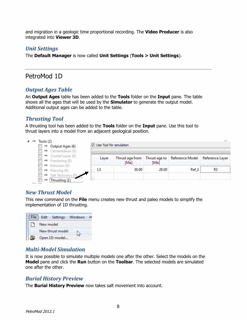
Thrusting Tool A thrusting tool has been added to the Tools folder on the Input pane. Use this tool to thrust layers into a model from an adjacent geological position.
New Thrust Model This new command on the File menu creates new thrust and paleo models to simplify the implementation of 1D thrusting.
Multi-Model Simulation It is now possible to simulate multiple models one after the other. Select the models on the Model pane and click the Run button on the Toolbar. The selected models are simulated one after the other.
Burial History Preview The Burial History Preview now takes salt movement into account.
9 Release Notes
Sch
lum
be
rger P
ub
lic
Simulator Options By default the Use Previous Run option is now turned off.
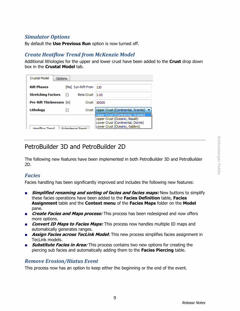
Create Heatflow Trend from McKenzie Model Additional lithologies for the upper and lower crust have been added to the Crust drop down box in the Crustal Model tab.
PetroBuilder 3D and PetroBuilder 2D The following new features have been implemented in both PetroBuilder 3D and PetroBuilder 2D.
Facies Facies handling has been significantly improved and includes the following new features: ■ Simplified renaming and sorting of facies and facies maps: New buttons to simplify
these facies operations have been added to the Facies Definition table, Facies Assignment table and the Context menu of the Facies Maps folder on the Model pane.
■ Create Facies and Maps process: This process has been redesigned and now offers more options.
■ Convert ID Maps to Facies Maps: This process now handles multiple ID maps and automatically generates ranges.
■ Assign Facies across TecLink Model: This new process simplifies facies assignment in TecLink models.
■ Substitute Facies in Area: This process contains two new options for creating the piercing sub facies and automatically adding them to the Facies Piercing table.
Remove Erosion/Hiatus Event This process now has an option to keep either the beginning or the end of the event.

10 PetroMod 2012.1
Sch
lum
be
rger P
ub
lic
Split Layer Process The behavior of the Follow Well Picks option has changed. A pick is now active when at least one instance of the pick is in the selected layer (previously a pick was active only if all instances of the pick were in the selected layer).
1D Extraction The 1D Extraction function contains a new check box called Remove redundant sublayers. When each sublayer in a layer contains the same facies, the sublayers are considered “redundant”. Tick this box to extract only the layer, not the redundant sublayers.
Create Heatflow Trend from McKenzie Model Additional lithologies for the upper and lower crust have been added to the Crust drop down box in the Crustal Model tab.
Model View Depth View has been renamed to Model View.
PetroBuilder 3D The following new features have been implemented in PetroBuilder 3D only.
Collect Model Faults by Name This is a new process in the Faults > Fault Workshop folder in the Processes pane. The process generates model faults from imported line maps. The model faults are generated according to the names of the imported fault lines.

11 Release Notes
Sch
lum
be
rger P
ub
lic
Export Faults Maps in the Fault Workshop and triangle maps can now be exported.
Map View Toolbar and Context Menu The map editing functions in Map View have moved from the main Toolbar to the Map View Toolbar. These functions also available via a context menu: Right-click anywhere in Map View to open the context menu.
Edit Layer Thickness The Edit Layer Thickness function enables users to edit layer thickness maps in Map View and apply the changes directly to layers. Negative thicknesses are shown in red for improved quality control.
Convert Selection Polygons to Line Map The Convert Selection Polygons to Line Map function is now available as a button on the
Map View Toolbar . It was previously only accessible via the Organizer.
Select Intersections A new selection tool for selecting the intersections of two maps is available on the Map View
Toolbar .
Clipping in 3D View The Clipping function on the 3D View Lower Toolbar now enables you to clip the model in
all directions . Click the down arrow and select a clipping direction. A dialog box will open. Use the slide bar or key in a value to set the clipping distance. Add another clipping in a different direction if required. A clipping remains active until you click select the clipping direction again to toggle it off.
PetroBuilder 2D The following new features have been implemented in PetroBuilder 2D only.
Import and Export Structural Data from/to Dynel The File menu contains new items for importing and exporting paleo sections from and to Dynel: New Dynel Based Model: Use this function to create a new TecLink model using data
from Dynel. It is equivalent to the New Line Based Model function.
Import Section from Dynel: Use this function to import additional Dynel sections into an existing TecLink model.
Export Section to Dynel: Export a paleo section to the Dynel file format.

12 PetroMod 2012.1
Sch
lum
be
rger P
ub
lic
Diagonal Faults Faults are now calculated diagonally across grid cells for a more accurate representation of faults and improved charge predictions.
Change Layer/Horizon Naming/Color A new option has been added to the Change Layer/Horizon naming/color process in the Layers folder of the Processes pane. It is now possible to rename horizons according to the names of the pre-grid horizons.
Anchor points on pre-grid lines The Edit pre-grid lines and Edit auxiliary lines functions now support the use of anchor points.
Auxiliary lines and polygons The Digitize New Auxiliary Lines and Digitize New Auxiliary Polygons dialogs contain a new option for changing the line color.
Edit Block Boundaries
A new button for editing block boundaries has been added to the 2D View Toolbar . This functionality was previously accessible from the Edit Pre-grid Lines button.
Simulator
Performance ■ Darcy migration runs are now 2 – 10 times faster. ■ IP migration runs are approx. twice as fast. ■ IP migration can now be run on multiple processors.
TSR (Thermochemical Sulfate Reduction) This is a new option in the Simulator Interface for including H2S in the migration calculation.
Diagonal Faults Faults are now calculated diagonally across grid cells in 2D models for a more accurate representation of faults and improved charge predictions.
General changes to algorithms Improvements to algorithms and convergence criteria might yield small differences in simulation results, e.g. for temperature, pressure and generation amounts, compared to previous versions of PetroMod. In particular, the pressure solution inside thin, high-permeable

13 Release Notes
Sch
lum
be
rger P
ub
lic
layers (e.g. sandstone layers) has been significantly improved. By using the special option “Oprm 1”, you can simulate the model using the PetroMod 2011.1 pressure solution.
Kinetics Editor
Compare Kinetic Reactions Curves (kinetics) can now be added to graphs in the Test tab. This enables kinetics to be graphically compared. Right-click on the graph and select Curves > Add curve …
SARA Kinetics New kinetics in accordance with the SARA scheme from the PEER Institute are available in the Kinetics Editor. The use of these kinetics is license controlled. Please contact the PetroMod support team to obtain the respective license.
There are TI, TII and TII SARA kinetics. The kinetics have the prefix “Tang(2011)_SARA_”.
• SARA kinetics should only be used with secondary cracking. Secondary cracking is a vital part of the overall SARA cracking scheme.
• A Pepper (1991) type component adsorption model is used for HC, CO2 and H2S source rock retention.
• CO2, H2S, and asphaltenes are retained by default in source rocks with high adsorption factors.
• PVT calibration was performed by adjusting C6-C14, C15+Sat, C15+Aro, NSO component
properties (MW, Tc, pc, , Se).
Lithology Editor
Calculate seal properties The calculate seal properties tool in the Seal Properties tab now enables users to calculate either capillary entry pressure or column height.
Well Editor
Well Completion A new table in the Well Editor enables users to enter information on well completion.

14 PetroMod 2012.1
Sch
lum
be
rger P
ub
lic
Convert Calibration Data from PetroMod 2011.1 This tool on the Edit menu fixes a known issue in Well Editor 2011. In PetroMod 2011 calibration data were saved to disk in the wrong unit. As a result, calibration data had the wrong values in other PetroMod modules. This bug has been fixed in PetroMod 2012.1, but when you open a project created in PetroMod 2011 with PetroMod 2012.1, the calibration data are read incorrectly. Use the Convert Calibration Data from v2011.1 tool in the PetroMod 2012.1 Well Editor to correct the calibration data. Note: the known issue is documented in the “Addendum to the PetroMod Well Editor User Guide” that can be downloaded from the PetroMod documentation page (PetroMod 2011) on the Schlumberger Support Portal.
PetroReport
New Source Statistics Pane The new Source Statistics pane shows the amount of hydrocarbons that were generated, expelled or accumulated in the selected source rocks at any given paleo time.
Multiple Models It is now possible to view data from multiple models at the same time in the Events pane.
Change Colors in the Events Pane It is now possible to change the colors of the curves in the Events pane (by changing the color of the corresponding cell in the Table).
New Behavior Option The new Behavior option in the Options pane enables users to control the way data is displayed in the Table and the Components and Events pane.
Unit Settings The Unit Settings function has been added to the Options menu on the Menu bar. Use this function to change the unit settings.
15 Release Notes
Sch
lum
be
rger P
ub
lic
Test Mode A new function called Test has been added to the Options menu on the Menu bar. Select the function to enter test mode. In test mode PetroReport checks whether the values in the Generation and Balance columns have been calculated correctly. Incorrect values are shown as “nan”. Click the Test function again to exit test mode.
Show oil and gas in different volume units on the Events pane A new scroll box on the Events pane enables users to select the volume units for oil components. Gas components continue to be shown according to the units that are set in the Options pane. This enables users to show gas and oil components in different units.
GOR The GOR can be shown in the Events pane.
Viewer 2D
Diagonal Faults Faults are now calculated and shown diagonally across grid cells in 2D models for a more accurate representation of faults and improved charge predictions.
Export Data This is a new function for exporting data to ASCII files. Users define which overlay information is exported for which layers at which events. Open the function from the File menu: File > Export Data.
Viewer 3D
Export/Import Polygons and Drainage Areas It is possible to export polygons, line maps and drainage areas from Viewer 3D. Imported line maps can be converted to polygons again to be used in PetroReport.
Generate Touchstone Input This is a new option in the Export Overlay Maps function for generating files that can be loaded into Touchstone.
Video Producer The new Video Producer enables users to generate animated videos of the burial history of 3D models. Use effects such as rotation and zooming to create videos containing all overlays and migration in a geologic time proportional recording.
16 PetroMod 2012.1
Sch
lum
be
rger P
ub
lic
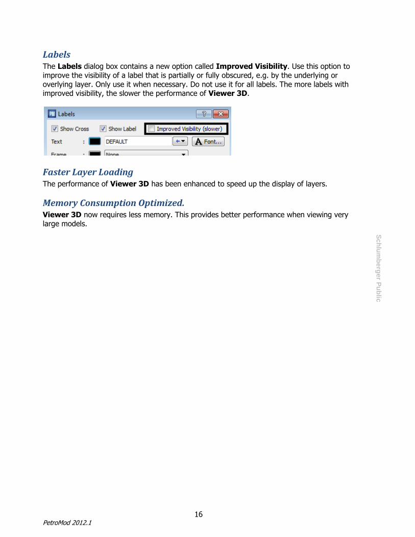
Labels The Labels dialog box contains a new option called Improved Visibility. Use this option to improve the visibility of a label that is partially or fully obscured, e.g. by the underlying or overlying layer. Only use it when necessary. Do not use it for all labels. The more labels with improved visibility, the slower the performance of Viewer 3D.
Faster Layer Loading The performance of Viewer 3D has been enhanced to speed up the display of layers.
Memory Consumption Optimized. Viewer 3D now requires less memory. This provides better performance when viewing very large models.
17 Release Notes
Sch
lum
be
rger P
ub
lic
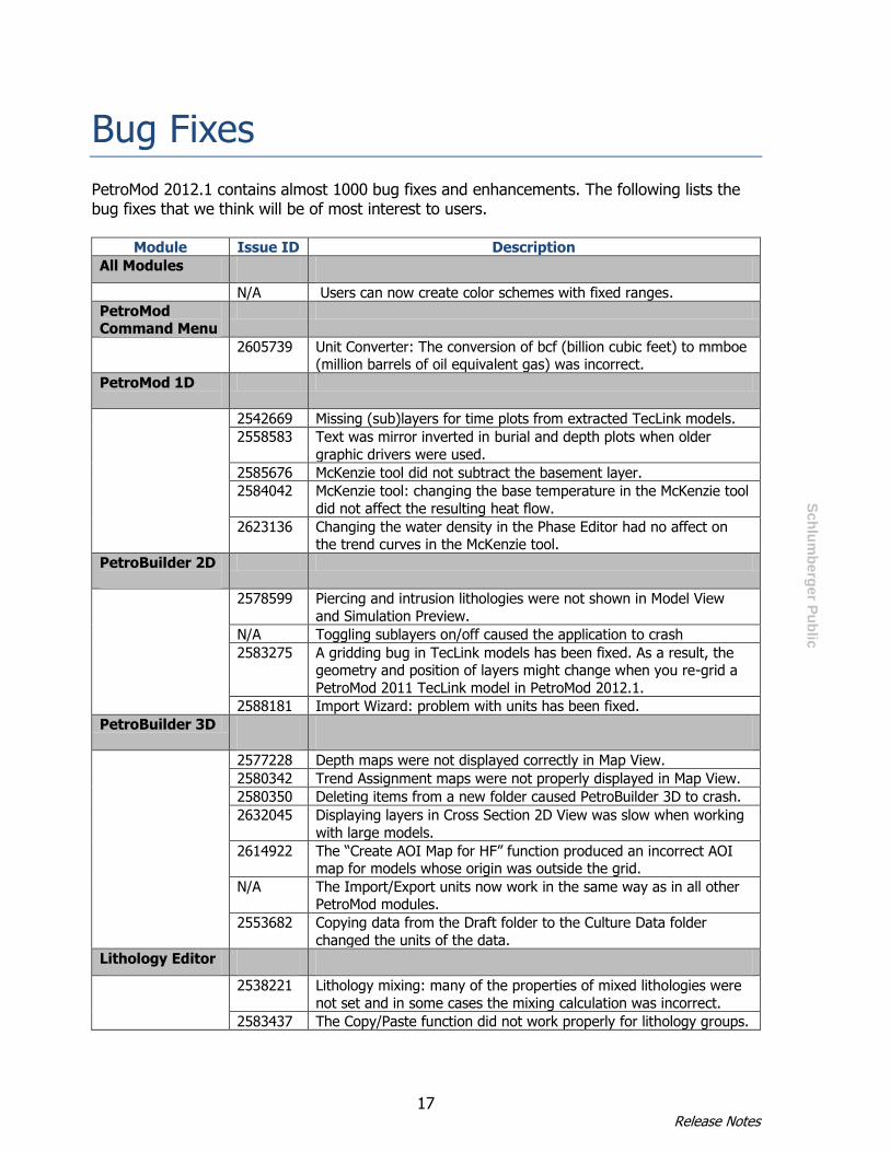
Bug Fixes
PetroMod 2012.1 contains almost 1000 bug fixes and enhancements. The following lists the bug fixes that we think will be of most interest to users.
Module Issue ID Description
All Modules
N/A Users can now create color schemes with fixed ranges.
PetroMod Command Menu
2605739 Unit Converter: The conversion of bcf (billion cubic feet) to mmboe (million barrels of oil equivalent gas) was incorrect.
PetroMod 1D
2542669 Missing (sub)layers for time plots from extracted TecLink models.
2558583 Text was mirror inverted in burial and depth plots when older
graphic drivers were used.
2585676 McKenzie tool did not subtract the basement layer.
2584042 McKenzie tool: changing the base temperature in the McKenzie tool
did not affect the resulting heat flow.
2623136 Changing the water density in the Phase Editor had no affect on the trend curves in the McKenzie tool.
PetroBuilder 2D
2578599 Piercing and intrusion lithologies were not shown in Model View
and Simulation Preview.
N/A Toggling sublayers on/off caused the application to crash
2583275 A gridding bug in TecLink models has been fixed. As a result, the geometry and position of layers might change when you re-grid a
PetroMod 2011 TecLink model in PetroMod 2012.1.
2588181 Import Wizard: problem with units has been fixed.
PetroBuilder 3D
2577228 Depth maps were not displayed correctly in Map View.
2580342 Trend Assignment maps were not properly displayed in Map View.
2580350 Deleting items from a new folder caused PetroBuilder 3D to crash.
2632045 Displaying layers in Cross Section 2D View was slow when working
with large models.
2614922 The “Create AOI Map for HF” function produced an incorrect AOI map for models whose origin was outside the grid.
N/A The Import/Export units now work in the same way as in all other PetroMod modules.
2553682 Copying data from the Draft folder to the Culture Data folder
changed the units of the data.
Lithology Editor
2538221 Lithology mixing: many of the properties of mixed lithologies were
not set and in some cases the mixing calculation was incorrect.
2583437 The Copy/Paste function did not work properly for lithology groups.
18 PetroMod 2012.1
Sch
lum
be
rger P
ub
lic
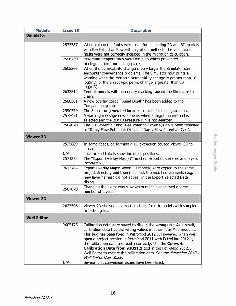
Module Issue ID Description
Simulator
2573587 When volumetric faults were used for simulating 2D and 3D models
with the Hybrid or Flowpath migration methods, the volumetric faults were not correctly included in the migration calculation.
2596739 Maximum temperatures were too high which prevented
biodegradation from taking place.
2605366 When the permeability change is very large, the Simulator can encounter convergence problems. The Simulator now prints a
warning when the isotropic permeability change is greater than 16 log(mD) or the anisotropic perm. change is greater than 10 log(mD).
2633514 TecLink models with secondary cracking caused the Simulator to crash.
2588501 A new overlay called “Burial Depth” has been added to the Compaction group.
2590379 The Simulator generated incorrect results for biodegradation.
2575471 A warning message now appears when a migration method is
selected and the 2D/3D Pressure run is not selected.
2584070 The “Oil Potential” and “Gas Potential” overlays have been renamed
to “Darcy Flow Potential: Oil” and “Darcy Flow Potential: Gas”.
Viewer 3D
2575689 In some cases, performing a 1D extraction caused Viewer 3D to
crash.
N/A Locator and Labels show incorrect positions.
2571273 The “Export Overlay Map(s)” function exported surfaces and layers
incorrectly.
2613784 Export Overlay Maps: When 3D models were copied to the same project directory and then modified, the modified elements (e.g.
new layer names) did not appear in the Export Selected Data
dialog.
2584070 Changing the event was slow when models contained a large
number of layers.
Viewer 2D
2627596 Viewer 2D showed incorrect statistics for risk models with sampled
or tartan grids.
Well Editor
2605175 Calibration data were saved to disk in the wrong unit. As a result, calibration data had the wrong values in other PetroMod modules.
This bug has been fixed in PetroMod 2012.1. However, when you open a project created in PetroMod 2011 with PetroMod 2012.1,
the calibration data are read incorrectly. Use the Convert Calibration Data from v2011.1 tool in the PetroMod 2012.1
Well Editor to correct the calibration data. See the PetroMod 2012.1 Well Editor User Guide.
N/A Several unit conversion issues have been fixed.

19 Release Notes
Sch
lum
be
rger P
ub
lic
Known Issues
All Modules Issue ID 2541011: GUI does not update correctly under Windows Vista and Windows 7
When running PetroMod on Windows Vista or Windows 7 with a non-Aero theme, the GUI often fails to update correctly.
Workaround: Change the theme to Aero:
1. Right-click on the Desktop and select Personalize. The Personalization dialog will open. 2. Select Window Color and Appearance. The Appearance Settings dialog will open. 3. Select “Windows Aero” and click OK.
Issue ID 2544113: On RHEL5 sessions saved using “Save Session As…” cannot be reopened
When users save a session using the “Save Session As…” command, the session is not automatically given the .xml extension. As a result, it cannot be reloaded.
Workaround: When saving a session, add “.xml” to the file name.
PetroMod 1D Issue ID 2640382: SWIT curve does not update after changing values in AutoSWIT
This issue concerns the AutoSWIT tool in the Boundary Conditions dialog. When you change the parameters in the AutoSWIT tool, the corresponding table in the boundary conditions dialog updates, but the plot does not. This is important because the values in the plot are used by the Simulator.
Workaround:
After changing values in the AutoSWIT tool, toggle the AutoSWIT tool off and on (turn the check box off/on) to update the plot.
Issue ID 2615160: Legend does not show overlay name
The legend on 1D plots does not show the full name of the overlay. For example, “TR_Pepper&Corvi TIIH” and “TR_Pepper&Corvi TII” both appear as “Transformation Ratio [%]” in the legend.

20 PetroMod 2012.1
Sch
lum
be
rger P
ub
lic
Issue ID 2544061: Name of calculated overlays is not shown on legend on burial plots
When users create a calculated overlay, the name of the overlay does not appear on the legend of burial plots.
Issue ID 2615153: Calibration points are missing from the legend When calibration data is plotted, for e.g. on a depth plot, the calibration data appears on the plot but is not shown in the legend.
Issue ID 2511554: User-created plots must be saved before simulation
User-created plots are not saved as part of the model when users click the Save button on the main Toolbar. This is the intended behavior. The plots are part of the project data and need to be saved as project plots. Please refer to section “5.5. Saving Plots” in the PetroMod 1D User Guide.
Issue ID 2540239: Extractions of user-generated overlays are not displayed Depth extractions of user-generated overlays from either Viewer 2D, Viewer 3D, or Viewer 3D V11 are not displayed in PetroMod 1D.
Issue ID N/A: 1D Extractions from PetroBuilder models with multiple erosions Due to differences in the Age Table concept, PetroMod 1D cannot properly handle extractions from PetroBuilder 2D and PetroBuilder 3D models with multiple erosions.
PetroBuilder 2D
Issue ID 2562161: Import Wizard cannot import grid-based data as maps Workaround:
1 Create a new map in the appropriate folder on the Model pane. 2 Double-click the map to open the Map Edit dialog. 3 Copy data from another model or spreadsheet and paste it into the table in the Map Edit
dialog. Issue ID 2579777: Create Heatflow Trend from McKenzie Model – PWD Trend is always used instead of Water Depth / Paleo Depth table
This process always uses the Paleo Water Depth Trend that is selected in the Crustal Model tab. If you do not specify a trend, the tool uses the Default_PWD trend.

21 Release Notes
Sch
lum
be
rger P
ub
lic
The Default_PWD trend is used even if the model has been built using values in the Water Depth / Paleo Depth table on the Model pane (instead of a trend).
Workaround: 1 Open the Trend Editor and create a new PWD trend. Leave it blank for now. 2 Extract a 1D model at the same location as your PWD trend. 3 Open PetroMod 1D and open the 1D model you extracted in step1. Open the Boundary
Conditions dialog and copy the PWD trend to the new PWD trend in the PetroBuilder 2D Trend Editor.
3 You can now use the new trend in the Create Heatflow Trend from McKenzie Model process.
Issue ID 2543069: Do not change the order of maps generated by Create Heatflow Maps from McKenzie Crustal Model
The Create Heatflow Maps from McKenzie Crustal Model process generates a number of maps that are listed in different folders on the Model pane. The order in which these maps are listed in the folders affects the curves in the 1D plots. Do not change the order of the maps in these folders! Doing so will result in incorrect 1D curves.
Issue ID N/A: “Save as” function does not save simulator settings When you save a model using the “Save as” function, the simulator settings are not saved. Make sure you check the simulator settings in these models after saving them.
Issue ID 2539364: Holes in gridded faults
When a fault consists of two or more segments, the gridding algorithm might grid them as separate faults. As a result, there could be gaps in gridded faults. Workaround:
Ensure that faults consist of only one segment before gridding. Issue ID 2523052: No session control
There is no session control in PetroBuilder 2D, i.e. it is not possible to save sessions and load sessions.
Issue ID 2632561: Fault property type FCP/Perm not calculated during conversion from PetroMod Version 11
One of the fault types in PetroMod Version 11 was “FCP”. In PetroMod 2011 and PetroMod 2012, the corresponding fault type is “FCP/Perm”. When models are converted from PetroMod 11 to PetroMod 2011, PetroMod 2011 expects permeability values or maps for these faults. Workaround: Use the following formula to calculate the permeability: Perm [log(mD)] = -8 * FCP[MPa]. Add the value to the Permeability column in the Fault Property Definition table.

22 PetroMod 2012.1
Sch
lum
be
rger P
ub
lic
PetroBuilder 3D Issue ID 2642134: Substitute Facies in Volume process
The Substitute Facies in Volume process only works when the depth maps and layers are turned on. Before using this process, tick the check boxes next to the Depth Maps and Layers folders on the Model pane.
Issue ID N/A: Several small bugs in McKenzie Crustal Heat Flow process
The Create Heatflow Maps from McKenzie Crustal Model process contains several small bugs that will be fixed in the next release.
Issue ID 2579777: Create Heatflow Trend from McKenzie Model – Default PWD Trend
See the description of the same known issue in PetroBuilder 2D.
Issue ID 2543069: Order of maps generated by Create Heatflow Maps from McKenzie Crustal Model affects the appearance of curves.
See the description of the same known issue in PetroBuilder 2D.
Issue ID 2632561: Fault property type FCP/Perm not calculated during conversion from PetroMod Version 11
See the description of the same known issue in PetroBuilder 2D. Issue ID 2492780: Imported facies maps must have same origin as model
This issue occurs when the origin of an imported IRAP Ascii facies map is different from the origin of your model. When the map is converted, PetroBuilder re-grids the map from draft resolution to model resolution. The re-gridding process grids the facies map to the origin of the model, resulting in the loss of the defined area of the imported map.
Issue ID 2539018: Default Layout function After re-arranging several windows, the Default Layout function does not always restore the layout as expected.
Issue ID 2542275: Extraction and injection points are not set correctly in Map View.
When the user tries to set an extraction point or injection point in Map View, the points are either set in the wrong place or are not visible. Workaround: Set the points in 3D View.
Issue ID 2523052: No session control There is no session control in PetroBuilder 3D, i.e. it is not possible to save sessions and load sessions.
Issue ID N/A: “Save as” function does not save simulator settings
See the description of the same known issue in PetroBuilder 2D.

23 Release Notes
Sch
lum
be
rger P
ub
lic
Issue ID 2640624: Display of negative thickness values When you open the Edit Layer Thickness tool, negative thicknesses are displayed in red. However, depending on the resolution, some small areas of negative thickness might not be displayed in red. Also, single grid points with negative thickness might not be displayed in red.
Viewer 2D Issue ID 2640748: Wrong CGR value in Accumulation Info box
The CGR value in the Accumulation Info box is too low by a factor of 5.614. Issue ID N/A: Gaps in 2D Models in Viewer 2D
Gaps can appear when viewing 2D models in Viewer 2D. This is a purely visual problem due to current limitations in Viewer 2D. The simulated model itself is complete and does not have any gaps. The gaps occur at locations where the cross-section turns through an angle and the turning point does not lie on a grid point.
2D View 3D View
The diagram on the right is from Viewer 2D looking down on the cross section of a 2D model (in the 3D View tab). The red rectangles mark the locations where the cross-section turns through an angle. The green line is a pre-grid horizon and represents the cross-section as entered by the user in PetroBuilder 2D. The black line is the cross-section as represented in Viewer 2D. You can see that the cross section in Viewer 2D does not turn at the same location as the pre-grid horizon. This is because the turning point of the pre-grid horizon does not lie on a grid point. Viewer 2D shifts the turning point to the adjacent grid point which results in gaps at these locations. As mentioned above, this a visualization problem only, there are no gaps in the simulated model.
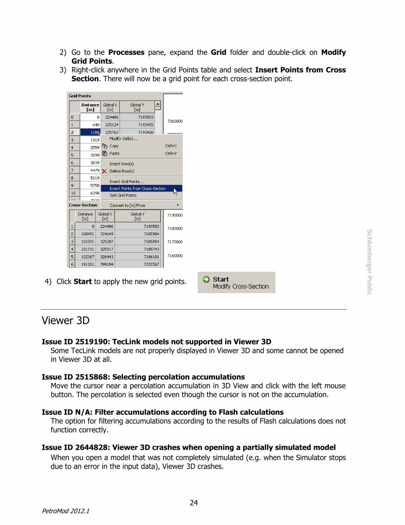
Workaround: Add grid points at each point where the cross-section turns through an angle. The easiest way is to insert a grid point for each cross-section point:
1) Open PetroBuilder 2D and load your model.
24 PetroMod 2012.1
Sch
lum
be
rger P
ub
lic
2) Go to the Processes pane, expand the Grid folder and double-click on Modify Grid Points.
3) Right-click anywhere in the Grid Points table and select Insert Points from Cross Section. There will now be a grid point for each cross-section point.
4) Click Start to apply the new grid points.
Viewer 3D Issue ID 2519190: TecLink models not supported in Viewer 3D
Some TecLink models are not properly displayed in Viewer 3D and some cannot be opened in Viewer 3D at all.
Issue ID 2515868: Selecting percolation accumulations Move the cursor near a percolation accumulation in 3D View and click with the left mouse button. The percolation is selected even though the cursor is not on the accumulation.
Issue ID N/A: Filter accumulations according to Flash calculations The option for filtering accumulations according to the results of Flash calculations does not function correctly.
Issue ID 2644828: Viewer 3D crashes when opening a partially simulated model
When you open a model that was not completely simulated (e.g. when the Simulator stops due to an error in the input data), Viewer 3D crashes.

25 Release Notes
Sch
lum
be
rger P
ub
lic
Simulator Issue ID 2587183: Hydrocarbons inside intrusion body
Hydrocarbon accumulations remain inside the intrusion body and are not vaporized as they should be.
Issue ID 2604436: Migration at block boundaries in TecLink models
In a TecLink model, when there is an open fault at a block boundary and a reservoir rock on the left and right of the boundary, the hydrocarbons pass through the fault.
Issue ID 2606617: Fault Saturation overlay is not realistic
The Fault Saturation overlay does not show realistic results in some models.
Issue ID 2620221: PetroReport shows incorrect values for TecLink models Although this issue is visible in PetroReport, the cause of the issue is in the Simulator which generates incorrect values.
Issue ID 2645722: Masses shown in PetroReport might be incorrect for models simulated with IP in parallel. “Accumulated in Reservoir” and “Migration Losses” might be calculated incorrectly in parallel IP runs when lateral facies variations are present in reservoir layers. For the affected facies, accumulated masses are not shown in the “Accumulated in Reservoir” column (which is zero in this case), but are erroneously added to the “Migration Losses” column. Workaround: Use a serial simulation or contact PetroMod support for a parallel workaround.
Issue ID 2627038: Faults are not calculated when periods are listed from latest to earliest in TecLink models
When faults with multiple time periods are included in TecLink models, the results depend upon the order of the fault periods in the Fault Property Definition table. For each fault, the periods should be listed from earliest to latest; otherwise the fault may be incorrectly deactivated during many paleo times.
Issue ID 2629978: Parallel simulation on Linux Command line parameters containing spaces (e.g. when the path name contains spaces), prevent models from being simulated on parallel processors.
Issue ID 2633585: IP migration does not generate gas hydrate masses When models are simulated using Invasion Percolation, migration pathways cross the gas hydrate stability zone without generating gas hydrates.
Issue ID 2638589: 2D diagonal faults on parallel processors
Simulating 2D diagonal faults using the Hybrid or Darcy migration method on parallel processors causes errors. When this occurs, the Simulator stops with an error message.

26 PetroMod 2012.1
Sch
lum
be
rger P
ub
lic
Workaround: Simulate the model on a single processor. Or Use the special option Odfg 0 to switch off diagonal faults.
Issue ID 2626329: Incorrect accumulation column heights
When a closed or partially open fault (FCP fault) runs through a flowpath layer, the accumulations on either side of the fault might have different column heights. This issue can occur for models simulated using either the Hybrid or Darcy migration method.
Issue ID 2634426: Crustal Layer model does not take half-depth value into account
The (radiogenic heat) half depth value of a lithology (if non-zero) specifies the rate with which the radiogenic heat production in a layer of that lithology should decrease with depth. This value can be set in the Lithology Editor (Radiogenic Heat tab). The half depth value applies to crustal layer models only. The crustal layer model calculation in the Simulator does not consider this half depth value. Consequently, the overall radiogenic heat production is higher than it should be.
Issue ID N/A: Convection does not work with locally refined volumetric faults For convection through faults, use the Volumetric Elements option in the Simulator interface (PetroFlow > Fault Method).
Issue ID 2513022: Simulator interface disappears (crashes)
The Simulator interface might close (crash) when simulating more than one model simultaneously. The crash only concerns the interface. The Simulator continues to process the model even though the interface has disappeared. You can open the Simulator interface again when the simulation has finished.
Issue 2646726: TecLink and diagonal volumetric refined faults When TecLink models are simulated with diagonal volumetric refined faults, the calculated pressures might be wrong.
Workaround: Either turn off diagonal fault gridding by using the special option “Odfg 0” or turn off volumetric fault refinements by changing the fault method to “Boundary Elements” in the Simulator Interface.
Issue ID N/A: 3D faults extending beyond AOI cause the simulator to crash on IP runs
When simulating a 3D model with invasion percolation, the simulation crashes if the faults extend beyond the model’s AOI. Workaround: Crop the faults in PetroBuilder 3D to ensure they do not extend beyond the AOI.
27 Release Notes
Sch
lum
be
rger P
ub
lic
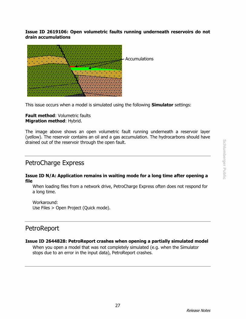
Issue ID 2619106: Open volumetric faults running underneath reservoirs do not drain accumulations
This issue occurs when a model is simulated using the following Simulator settings: Fault method: Volumetric faults Migration method: Hybrid. The image above shows an open volumetric fault running underneath a reservoir layer (yellow). The reservoir contains an oil and a gas accumulation. The hydrocarbons should have drained out of the reservoir through the open fault.
PetroCharge Express Issue ID N/A: Application remains in waiting mode for a long time after opening a file
When loading files from a network drive, PetroCharge Express often does not respond for a long time. Workaround: Use Files > Open Project (Quick mode).
PetroReport Issue ID 2644828: PetroReport crashes when opening a partially simulated model
When you open a model that was not completely simulated (e.g. when the Simulator stops due to an error in the input data), PetroReport crashes.
Accumulations
28 PetroMod 2012.1
Sch
lum
be
rger P
ub
lic
Lithology Editor Issue ID N/A: Mixing lithologies
Multipoint curves cannot be mixed. Formulae cannot be used when mixing lithologies. Problems may arise when mixing two or more properties from different theoretical
schemes (e.g. Athy’s depth law for compaction and Schneider’s effective stress formulation for compaction).
Well Editor Issue ID 2640463: Incorrect unit settings when importing deviation data
When you import deviation data, the Well Editor assumes that the x,y coordinates and the
true vertical depth/measured depth are stored in meters in the file, regardless of the
Import/Export settings. For example: if a true vertical depth value is stored in the file as
100 ft, the Well Editor interprets the value as 100 m. If the Display Unit is set to feet, the
Well Editor will import the value as 328 ft
Workaround:
When importing deviation data that is not in meters, do not use the import functions in
Well Editor. Instead, copy and paste the data into the Deviation table.
Issue ID 2640427: Importing LAS files
If your LAS file contains depth values in meters, you can ignore this issue.
If your LAS file contains depth values in a unit other than meters (e.g. feet), the depth
values will be imported incorrectly. Use the workaround described below.
Workaround:
Before importing the data, check the header of the LAS file. The keyword after “Depth” in
the header indicates the unit in which the depth information is stored. Depending on the
keyword, perform one of the following:
A - If you are importing depth data in feet and the keyword contains a capital “F”:
1 Import the LAS file. The log curves will be imported but they will have the wrong
depth values.
2 Make sure the Display Unit in Well Editor is set to “ft” (File > Unit Settings)
3 For each imported log curve: i. Select the log curve on the Well Browser

29 Release Notes
Sch
lum
be
rger P
ub
lic
ii. In the Table View, select all the imported depth values (Measured Depth
column).
iii. Right-click > Convert to [ft] from [meter]. The imported depth data will now
have the correct values.
B - If you are importing depth data in feet and the keyword does NOT contain a capital
“F”:
1 Import the LAS file. The log curves will be imported but they will have the wrong
depth values
2 Make sure the Display Unit in Well Editor is set to “meter” (File > Unit Settings)
3 For each imported log curve: i. Select the log curve on the Well Browser ii. In the Table View, select all the imported depth values (Measured Depth
column).
iii. Right-click > Convert to [meter] from [feet]
4 You can now change the Display Unit to “ft” (File > Unit Settings)
C - If you are importing depth data in any other unit and the keyword does NOT contain a
capital “F”:
Proceed in the same way as in B. Replace “feet” in Step 3 iii and “ft” in Step 4 with
your unit.

30 PetroMod 2012.1
Sch
lum
be
rger P
ub
lic
System Requirements
Hardware requirements
For workstations (e.g. Dell T7500)
Processor CPU 2 x Intel X5667 (quad core) or X5675 (hexa core)
Memory 12 GB RAM
Disk space 5GB of free disk space
Graphics Nvidia Quadro 5000
Network card 1000 Mbit Nic
For laptops (e.g Dell M4600)
Processor Intel Core i7-2860Q 2.5 GHz
Memory 16 GB RAM
Disk space 5GB of free disk space
Graphics Nvidia Quadro 2000M
For Linux clusters
Processor CPU 2 x Intel X5667 (quad core) or X5675 (hexa core)
Memory 48 GB RAM
Disk space 5GB of free disk space
Network card 1000 Mbit Nic
Software requirements
Microsoft Vista 64-bit
Microsoft Windows 7 (recommended) 64-bit
RedHat Enterprise Linux 5.3 (recommended) 64 bit
Microsoft.NET Framework 2.0
IMPORTANT for Windows users: Several visualization issues in PetroMod 2011 were due
to the use of older graphic drivers. Only the Nvidia driver versions 295.73 and later provide built-in support for PetroMod. We strongly recommend installing these drivers to ensure optimal visualization and avoid visualization problems.

31 Release Notes
Sch
lum
be
rger P
ub
lic
Warning for RHEL 5 users: Due to known issues concerning the instability of OpenGL graphics, PetroMod only supports local rendering on 3D graphic cards with stable graphic drivers. Rendering via a network could cause stability issues. In particular, we observed problems with the Mesa OpenGL package that is delivered with RHEL5 and works as a fall-back when no other driver is installed.
Note for Microsoft Windows users: When running PetroMod on Windows Vista or
Windows 7 with a non-Aero theme, the GUI often fails to update correctly. Change the theme to “Aero” to resolve this issue (see also Issue ID 2541011 in the Known Issues section).
Note for Microsoft Windows 7 and RedHat Enterprise Linux 5.3 users: We
recommend installing the latest graphics drivers available from Nvidia or ATI to avoid OpenGL graphic display errors. In most cases the driver version that comes with the operating system is quite old. Moreover, generic drives are used when the graphics hardware is not recognized correctly during installation of the operating system. These drivers only support basic functionality and do not offer the OpenGL features required by PetroMod. Please be aware that most onboard graphics hardware does not support OpenGL at all. A dedicated graphics card is required for PetroMod.
Recommended: If your notebook has an integrated graphic unit in the processor (GPU), as
is the case with the Intel Sandy Bridge processor, we recommend disabling the GPU in the BIOS. This will help you avoid performance problems and visualization errors.
32 PetroMod 2012.1
Sch
lum
be
rger P
ub
lic
Licensing
Licenses are required to access PetroMod. Certain functionalities or modules are only available with the respective licenses. Contact your Schlumberger SIS Customer Support representative to obtain the necessary licenses. Maintenance contracts are usually yearly contracts, renewed at any time during the year. Prior to 2012.1, PetroMod licenses allowed you to step up to a new PetroMod version based on the PetroMod license expiration date without having a valid maintenance contract. Beginning with 2012.1, upgrades are based on your maintenance contract expiration date. This is how you read the new licensing format: FEATURE petrobuilder3D slbsls <yyyy.mm> <dd-mmm-yyyy> <#> Where • <yyyy.mm> is the maintenance expiration year and month • <dd-mmm-yyyy> is the license expiration day, month, year • <#> is the number of licenses Maintenance renewal is required to run any PetroMod version released after your maintenance expiration date. You will be automatically contacted by Schlumberger Information Systems before your maintenance expires.
Module-based licensing PetroMod 2012 uses a module-based licensing concept. The benefits are:
Easier to understand as the module names describe the functions. More flexibility to match clients’ needs and configure specific packages at a lower cost.
Ability to offer lower-cost entry level options. Functionality and maintenance fees for already purchased packages will not change for
existing clients. Purchasing of lower-cost modules will make it easier for clients to order quickly, based
on their immediate requirements.
Previous PetroMod packages will still be offered. The following table lists all available PetroMod modules.

33 Release Notes
Sch
lum
be
rger P
ub
lic
PetroMod 1D PetroMod 2D PetroMod 3D
PetroMod 1D
2D Model Builder 3D Model Builder
PM1D PetroRisk PM2D Model Builder PM3D Model Builder
2D Pressure-Temperature Simulation 3D Pressure-Temperature Simulation
PM2D Multi-1D Pressure-Temperature PM3D Multi-1D Pressure-Temperature
PM2D Full 2D Pressure-Temperature PM3D Full 3D Pressure-Temperature
2D Kinetics Models 3D Kinetics Models
PM2D 2-Component PM3D 2-Component
PM2D Multi-Component PM3D Multi-Component
2D Petroleum Migration Simulation 3D Petroleum Migration Simulation
PM2D Flowpath PM3D Flowpath
PM2D Invasion Percolation PM3D Invasion Percolation
PM2D Hybrid PM3D Hybrid
2D Add-ons 3D Add-ons
PM2D PetroRisk PM3D PetroRisk*
PM2D TecLink PM3D Geomechanics
PM2D Geomechanics PM3D Gas Hydrates
PM2D Gas Hydrates PM3D Thermal Calibration
PM2D Crustal Modeling PM3D Biodegradation
PM3D Local Grid Refinement (LGR)
PM3D Crustal Modeling
2D and 3D Add-ons
PM Parallel Processing PM SARA Kinetics
PM 14-Component Phase Kinetics PM TSR Modeling
34 PetroMod 2012.1
Sch
lum
be
rger P
ub
lic
Support
Support for PetroMod software is supplied by the Schlumberger Customer Care Center. Please go to the Schlumberger Support Portal at https://support.slb.com and follow the general PetroMod support procedures.
Supporting Documentation The following documentation for PetroMod 2012.1 is available on the Schlumberger Support Portal at http://support.slb.com
PetroMod 2012.1 Installation Guide
PetroMod 2012.1 Release Notes
PetroMod 2012.1 Command Menu User Guide
PetroMod 2012.1 PetroMod1D User Guide
PetroMod 2012.1 PetroBuilder 2D User Guide
PetroMod 2012.1 2DTecLink Reference Guide
PetroMod 2012.1 PetroBuilder 3D User Guide
PetroMod 2012.1 Simulator User Guide
PetroMod 2012.1 Viewer 2D User Guide
PetroMod 2012.1 Viewer 3D User Guide
PetroMod 2012.1 Map Editor User Guide
PetroMod 2012.1 Kinetics Editor User Guide
PetroMod 2012.1 Lithology Editor User Guide
PetroMod 2012.1 Well Editor User Guide
PetroMod 2012.1 Time Scale Editor User Guide
PetroMod_2012.1 PetroRisk User Guide
PetroMod 2012.1 PetroReport User Guide
PetroMod_2012.1 Facies Refinement Tool Reference Guide
PetroMod_2012.1 Heat Flow Calibration Tool Reference Guide
PetroMod 2012.1 Biodegradation, Geomechanics and Gas Hydrates Reference Guide