Embed Size (px)
Citation preview

Betriebsanleitung • Operating InstructionsP
K 0
21
7 B
E/O
(0
90
6)
Translation of the Original Operating Instruction
Diaphragm Pump
MVP 020-3 AC
MVP 020-3 DC
s

2
Table of contents
Table of contents
1 About this manual . . . . . . . . . . . . . . . . . . . . . . . . . . . . . . . . . . . . . . 3
1.1 Validity. . . . . . . . . . . . . . . . . . . . . . . . . . . . . . . . . . . . . . . . . . . . . . . . 3
1.2 Conventions . . . . . . . . . . . . . . . . . . . . . . . . . . . . . . . . . . . . . . . . . . . 3
2 Safety . . . . . . . . . . . . . . . . . . . . . . . . . . . . . . . . . . . . . . . . . . . . . . . . 4
2.1 Safety precautions . . . . . . . . . . . . . . . . . . . . . . . . . . . . . . . . . . . . . . 4
2.2 Proper use. . . . . . . . . . . . . . . . . . . . . . . . . . . . . . . . . . . . . . . . . . . . . 5
2.3 Improper use . . . . . . . . . . . . . . . . . . . . . . . . . . . . . . . . . . . . . . . . . . . 5
3 Transport and storage . . . . . . . . . . . . . . . . . . . . . . . . . . . . . . . . . . 6
3.1 Transport . . . . . . . . . . . . . . . . . . . . . . . . . . . . . . . . . . . . . . . . . . . . . . 6
3.2 Storage . . . . . . . . . . . . . . . . . . . . . . . . . . . . . . . . . . . . . . . . . . . . . . . 6
4 Product description . . . . . . . . . . . . . . . . . . . . . . . . . . . . . . . . . . . . 7
4.1 Product identification . . . . . . . . . . . . . . . . . . . . . . . . . . . . . . . . . . . . . 7
4.2 Function . . . . . . . . . . . . . . . . . . . . . . . . . . . . . . . . . . . . . . . . . . . . . . 8
5 Installation . . . . . . . . . . . . . . . . . . . . . . . . . . . . . . . . . . . . . . . . . . . . 9
5.1 Setting up the pump . . . . . . . . . . . . . . . . . . . . . . . . . . . . . . . . . . . . . 9
5.2 Connecting the vacuum side . . . . . . . . . . . . . . . . . . . . . . . . . . . . . . . 9
5.3 Connecting the exhaust side . . . . . . . . . . . . . . . . . . . . . . . . . . . . . . . 9
5.4 Connecting to the mains power supply . . . . . . . . . . . . . . . . . . . . . . 10
6 Operation . . . . . . . . . . . . . . . . . . . . . . . . . . . . . . . . . . . . . . . . . . . . 12
6.1 Before switching on the pump. . . . . . . . . . . . . . . . . . . . . . . . . . . . . 12
6.2 Control signals. . . . . . . . . . . . . . . . . . . . . . . . . . . . . . . . . . . . . . . . . 12
6.3 Switching on the pump . . . . . . . . . . . . . . . . . . . . . . . . . . . . . . . . . . 13
6.4 Pumping condensable vapours . . . . . . . . . . . . . . . . . . . . . . . . . . . . 14
6.5 Switching off . . . . . . . . . . . . . . . . . . . . . . . . . . . . . . . . . . . . . . . . . . 14
7 Maintenance. . . . . . . . . . . . . . . . . . . . . . . . . . . . . . . . . . . . . . . . . . 15
7.1 Precautions . . . . . . . . . . . . . . . . . . . . . . . . . . . . . . . . . . . . . . . . . . . 15
7.2 Cleaning and replacing diaphragm and valves . . . . . . . . . . . . . . . . 17
7.3 Checking the pump . . . . . . . . . . . . . . . . . . . . . . . . . . . . . . . . . . . . . 20
8 Decommissioning . . . . . . . . . . . . . . . . . . . . . . . . . . . . . . . . . . . . . 21
8.1 Shutting down for longer periods. . . . . . . . . . . . . . . . . . . . . . . . . . . 21
9 Malfunctions . . . . . . . . . . . . . . . . . . . . . . . . . . . . . . . . . . . . . . . . . 21
9.1 Rectifying malfunctions . . . . . . . . . . . . . . . . . . . . . . . . . . . . . . . . . . 22
10 Service . . . . . . . . . . . . . . . . . . . . . . . . . . . . . . . . . . . . . . . . . . . . . . 23
11 Spare parts . . . . . . . . . . . . . . . . . . . . . . . . . . . . . . . . . . . . . . . . . . 24
12 Accessories . . . . . . . . . . . . . . . . . . . . . . . . . . . . . . . . . . . . . . . . . . 24
13 Technical data . . . . . . . . . . . . . . . . . . . . . . . . . . . . . . . . . . . . . . . . 25
13.1 Substances in contact with the media . . . . . . . . . . . . . . . . . . . . . . . 26
13.2 Dimensions . . . . . . . . . . . . . . . . . . . . . . . . . . . . . . . . . . . . . . . . . . . 27
Declaration of conformity . . . . . . . . . . . . . . . . . . . . . . . . . . . . . . 28

About this manual
1 About this manual
1.1 ValidityThis operating manual is for customers of Pfeiffer Vacuum. It describes the func-
tioning of the designated product and provides the most important information for
safe use of the unit. The description follows applicable EU guidelines. All informa-
tion provided in this operating manual refer to the current state of the product's de-
velopment. The documentation remains valid as long as the customer does not
make any changes to the product.
Up-to-date operating instructions can also be downloaded from
www.pfeiffer-vacuum.net.
Applicable docu-
ments
*also available via www.pfeiffer-vacuum.net
For information about other certifications, if applicable, please see the signet on
the product or:
• www.tuvdotcom.com
• TUVdotCOM-ID 0000021320
1.2 Conventions
Safety instructions The safety instructions in Pfeiffer Vacuum operating manuals are the result of risk
evaluations and hazard analyses and are oriented on international certification
standards as specified by UL, CSA, ANSI Z-535, SEMI S1, ISO 3864 and DIN 4844.
In this document, the following hazard levels and information are considered:
MVP 020-3 AC/DC Operating instructions
Safety information for vacuum pumps "Safety Guide" PT 0300 BN*
Declaration of Conformity Part of this document
Operating instructions for accessories (order-specifically) see section "accessories"*
DANGER
Immediate danger
Death or very severe injuries can occur.
WARNING
Possible danger
Injuries or severe property damages can occur.
CAUTION
Possible danger
Injuries or prperty damages can occur.
NOTE
Command or note
Command to perform an action or information about properties, the disregarding of which may result in damage to the product.
3

Safety
Pictograph
definitions
Instructions in the
text
Work instruction: here you have to do something.
Symbols used The following symbols are used consistently throughout in all illustrations:
Vacuum flange
Power connection
Exhaust flange
2 Safety
2.1 Safety precautions
• Before pumping dangerous, corrosive or environmentally hazardous media,
take suitable precautions:
– Test the compatibility with substances in contact with the media.
– Prevent the release of process gases and their reaction products and by-pro-
ducts or dispose of them according to the relevant regulations.
– Safety measures (e.g. wearing protective clothing and safety goggles) to pre-
vent inhalation and skin contact.
Prohibition of an action or activity in connection with a
source of danger, the disregarding of which may result in
serious accidents.
Warning of a displayed source of danger in connection
with operation of the unit or equipment.
Command to perform an action or task associated with a
source of danger, the disregarding of which may result in
serious accidents.
V
NOTE
Duty to inform
Each person involved in the installation, operation or maintenance of the vacuum pump must read and observe the safety-related parts of these operating instructions.
Absolute observe the safety information for vacuum pumps (PT 0300 BN) !The operator is obligated to make operating personnel aware of dangers originating
from the vacuum pump, the pumped medium and the entire system.
NOTE
Installation and operation of accessories
Pfeiffer Vacuum pumps can be equipped with a series of adapted accessories. The installation, operation and maintenance of connected devices are described in detail in the operating instructions of the individual components.
For information on the operating instructions of components, see "Accessories".Use original accessory parts only.
4

Safety
• Connect the vacuum pump to a shockproof socket only.
– Use only undamaged network cables which comply with the regulations.
– Make sure that the grounding is sufficient.
• Do not expose any body parts to the vacuum.
• Observe the safety and accident prevention regulations.
• Check regularly that all safety precautions are being complied with.
• Do not carry out any unauthorised modifications or conversions to the pumps.
• Depending on the operating and ambient conditions, the surface temperature of
the pumps may rise above 70 °C. Use suitable finger guards if necessary.
• The unit has been accredited with protection class IP 54/20. When installing into
ambient conditions, which afford other protection classes, the necessary measu-
res must be taken.
• When returning the pumps to us please note the instructions in the Service sec-
tion.
2.2 Proper use
• The vacuum pump may only be used to generate a vacuum.
• Installation, operating and maintenance regulations must be complied with.
• Other accessories than those described in this manual must not be used without
the agreement of Pfeiffer Vacuum.
• When pumping gases which could form explosive or ignitable mixtures, take
suitable precautions:
– If necessary, connect inert gas for ventilation or gas ballast supply.
2.3 Improper useImproper use will cause all claims for liability and guarantees to be forfeited. Im-
proper use is deemed to be all use for purposes deviating from those mentioned
above, especially:
• Pumping of corrosive or explosive media.
• Operation of the pump in potentially explosive areas.
• Pumping of gases containing impurities such as particles, dusts and condensate;
note the vapour compatibility levels of the pump.
• Pumping of substances that tend to sublime.
• Use of the vacuum pump to generate pressure.
• Pumping of liquids.
• Connection to pumps or units which are not suitable for this purpose according
to their operating instructions.
• Connection to units which have exposed voltage-carrying parts.
NOTE
CE conformity
The manufacturer's declaration of conformity becomes invalid if the operator modifies the original product or installs additional components.
Following installation into a plant and before commissioning, the operator must check the entire system for compliance with the valid EU directives and reassess it accordingly.
5

Transport and storage
3 Transport and storage
3.1 Transport
Remove the locking cap from the vacuum and fore-vacuum flange immediately
before connecting!
Use only the handles provided for that purpose to lift the pump.
– Do not use the interhead connections on the top side of the pump to carry the
pump.
3.2 Storage
Check that all the openings on the pump are securely closed.
Store the pump in a cool, dry place; preferably at room temperatures (approx.
20°C).
– For a longer period of storage, seal the pump in a PE bag with drying agents
enclosed.
6

Product description
4 Product description
4.1 Product identificationTo correctly identify the product when communicating with Pfeiffer Vacuum, al-
ways have the information from the rating plate available.
• Pump model and model number
• Serial number
• Date of manufacture
Scope of delivery • Pump with drive unit
• Operating instructions
Differences between
the pump versions Characteristic MVP 020-3 AC MVP 020-3 DC
Flange (in)• G 1/8" elbow union + enclosed hose DN 6
x 1000 mm with a elbow union in G 1/4" at the end
• G 1/8" + hose wave DN 6
Flange (out) • G 1/8" + hose wave DN 6 • G 1/8" + silencer
Mains requirement: voltage (selectable)
100-120/200-230 V, 50/60 Hz 24 V (+/- 10 %)
Variable speed function
no yes, via control voltage
7

Product description
4.2 FunctionThe diaphragm vacuum pumps of the series MVP 020-3 AC/DC are three stage, dry
compressor vacuum pumps. The pumps are positive displacement pumps with a
periodic change of size of the suction chamber produced by the movement of the
diaphragm. The gas flow causes the valves to open and close automatically. The
pump units are directly connected to the drive motor.
Fig. 1: MVP 020-3 AC
Fig. 2: MVP 020-3 AC
1 Vacuum connection
2 Exhaust (with silencer)
9 Handle, removable
10 Interhead connection
11 Banjo bolt
13 Mains connection with secu-
ring ring and main switch
14 Voltage selection switch
20 Screw plug
20.1 Purge orifice, optional
1 Vacuum connection
2 Exhaust (with silencer)
9 Handle, removable
10 Interhead connection
11 Banjo bolt
13 Power supply connection
16 Connection control voltage
20 Screw plug
20.1 Purge orifice, optional
10
9
2
13
1420/20.1
111
V
10
11
9
2
1316
20/20.1
1
V
8

Installation
5 Installation
5.1 Setting up the pump
Installation location Observe the following requirements when setting up the pump:
• Consider the load-bearing capacity of the installation site.
• Maximum installation altitude 2000 m (above mean sea level)
• Permissible ambient temperature: +12 ... 40°C
• Maximum relative humidity 85%
Always place the pump on a firm, even surface.
– Where stationary installation is involved, anchor the pump on site.
When installing the pump in a closed housing, ensure there is sufficient air cir-
culation.
– Voltage and frequency information given on the motor rating plate must be
visible.
– If vacuum pump is installed above 1000 m above mean sea level check com-
patibillity with applicable safety requirements, e.g. DIN EN 61010 (motor may
overheat due to insufficient cooling).
5.2 Connecting the vacuum side
Remove locking cap on intake connection and connect vacuum pump to the ap-
paratus.
The connection between the pump and the recipient should be kept as short as
possible.
– Depending on the pump type, use metallic hoses or PVC hoses with flange
connections.
– Separators, filters etc. may be installed upstream to protect the pump (see ac-
cessories). However, please observe the loss of pumping capacity due to the
conductivity of the accessories.
5.3 Connecting the exhaust side
Choose the cross-section of the exhaust line to be at least the size of the nominal
connection diameter of the vacuum pump's exhaust connection.
Piping to the pump must be suspended or supported.
– Physical forces from the piping system must not be allowed to act on vacuum
pumps.
Lay piping from the pump sloping downward so that no condensate can flow
back into the pump; otherwise fit a condensate separator.
– If an air trap is created in the system, then a device for draining condensation
water must be provided at the lowest point.
CAUTION
High pressure in the exhaust line!
Danger of damage to the seals and danger of the pump bursting.
Install the line without shut-off valves on the exhaust side.Pumpe nicht mit Überdruck am Einlass betreiben; max. zulässige Drücke und Druck-
differenzen beachten.
9

Installation
5.4 Connecting to the mains power supplyThe pump is driven by single-phase extended voltage range motors with revers-
ible voltage ranges.
Single phase motors The mains voltage must be determined on-site each time before the pump is in-
stalled or moved to a different location.
Changing the voltage range
Disconnect the pump from the power supply.
Set the desired voltage range on the voltage selector switch using a suitable
screwdriver.
WARNING
Emission of toxic substances from the exhaust!
Danger of poisoning from emitted gases or vapours, which can be detrimental to health and/or can pollute the environment, depending on the particular application.
Comply with the applicable regulations when working with toxic substances.Only officially approved filter systems may be used to separate and remove these
substances.
CAUTION
Excess voltage!
Danger of destroying the motor.
Power connections must comply with local regulations. Voltage and frequency infor-mation given on the motor rating plate must correspond to the mains voltage and frequency values.
To protect the motor and supply cable in case of malfunction, mains fuse protection must be implemented.
NOTE
Overvoltage!
An incorrect voltage range setting can damage the motor.
Disconnect the pump from the power supply.Only change the voltage range when the pump is disconnected from the power
mains.
10

Installation
Motor protection
A self-locking thermal winding protector switches off the pump motor in the event
of overheating.
Allow the pump to cool off several minutes and do not switch it back on until it
has cooled off.
Intermittend operation with TC via relay box (accessory)
Connection of diaphragm pumps in the pumping station according wiring diagram
in operating instructions of the Backing Pump Relay Boxes:
Fig. 3: Connection of MVP 020-3 AC with relaiy box (PM 061 372-T/374-T) to TC 110/400
MVP 020-3 DC In addition to the voltage input 13, the pump is equipped with a control signal
input 16.
Fig. 4: Connection of the MVP 020-3 DC at TC for intermittend operation
Switch position: "115" "230"
Voltage ranges: 90 ... 126 V, 50/60 Hz 180 ... 254 V, 50/60 Hz
115
230
115
230
115
230
3
accesso
ry A
MV
P-R
eih
e
MV
P s
eri
esTC
L
N
PEPENL´
4
13 16
13 Power supply, 4-pin socket 16 Control voltage, 2-pin plug
31
12
3
2nc
nc
TC 110
24 V/DC
ext.PE
TPSMVP 020-3 DC4
+ + +- - -
11
Operation
6 Operation
6.1 Before switching on the pump
Compare the voltage information on the rating plate with the mains voltage.
Check that the exhaust connection allows free flow (max. permissible pressure
1.1 bar absolute).
– Activate the shut-off valves in such a way that they open before or at the same
time as the pump is started.
Protect the pump sufficiently from taking in contaminants by means of suitable
precautions (e.g. dust filters).
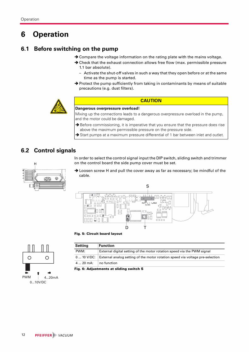
6.2 Control signals
In order to select the control signal input the DIP switch, sliding switch and trimmer
on the control board the side pump cover must be set.
Loosen screw H and pull the cover away as far as necessary; be mindful of the
cable.
Fig. 5: Circuit board layout
Fig. 6: Adjustments at sliding switch S
CAUTION
Dangerous overpressure overload!
Mixing up the connections leads to a dangerous overpressure overload in the pump, and the motor could be damaged.
Before commissioning, it is imperative that you ensure that the pressure does rise above the maximum permissible pressure on the pressure side.
Start pumps at a maximum pressure differential of 1 bar between inlet and outlet.
H
S
D T
PWM
0...10V/DC
4...20mA
Setting Function
PWM: External digital setting of the motor rotation speed via the PWM signal
0 ... 10 V/DC: External analog setting of the motor rotation speed via voltage pre-selection
4 ... 20 mA: no function
12

Operation
Fig. 7: Adjustments at DIP switch
6.3 Switching on the pumpThe pump can be switched on in any pressure range between atmospheric and
ultimate pressure.
The pump attains the stated values for throughput rates and final pressure levels
only once the operating temperature is reached (after approximately 15 minutes).
Switch on the pump with the vacuum flange closed and allow to warm up for 15
minutes.
Intermittent Opera-
tions with turbo elec-
tronics
To prolong the life of diaphragm pumps, intermittent operations can be selected
with lesser gas throughputs of < 0.18 mbar l/s. This means that, dependent on the
TMP power take-up, the backing pump will be switched on and off. TMP power
take-up is dependent on the fore-vacuum pressure and gas throughput.
– By comparing the power take-up with an upper and a lower limit value, the re-
lative switch-on duration with lesser gas throughputs can be reduced to approx.
1 to 60%.
– To avoid too frequent switching on, the buffer volume in the fore-vacuum line
should amount to ≥0.5 liter from approx. 0.018 mbar l/s.
Note! For this operation mode there is no variable speed control possible.
Carry out adjustments at sliding switch and DIP switch for operation with PWM
signal.
Connect galvanic isolated PWM-signal to signal input 16.
– 0 V ==> Pump „off“
– 24 V ==> Pump „on“ (max. rotation speed)
Variable speed
control
Carry out adjustments at sliding switch and DIP switch for operation with PWM
signal.
Connect galvanic isolated PWM signal to signal input 16 for variable customized
speed control.
– (5V ... 24V); absolutely necessary!
– Frequency range: >100 Hz, < 1,5 kHz.
ON
1 21 2 Function
on on Setting the motor rotation speed via the trimmer (programming mode).
on off Interlocking the trimmer pre-selection as previously selected (operating mode).
off on External digital setting of the motor rotation speed via the PWM signal.
off offExternal analog setting of the motor rotation speed via voltage pre-selection (0 ... 10V/DC).
CAUTION
Hot surface!
Danger of burns if hot parts are touched. Depending on the operating and ambient conditions, the surface temperature of the pump may rise above 70 °C.
In this case, use suitable finger guards.
PWM signal < 25 % 25 % 25 % ... 75 % > 75 %
Number ofrevolutions
0 RPM 350 RPM Linear increasing 1600 RPM
13
Operation
6.4 Pumping condensable vapoursSteam or moisture from pumped media can condense in the vacuum pump and
hence impair the suction performance.
Purge orifice (option) The rate of expulsion of condensate can be increased by admitting a purge media
(air) and the pump will attain the specified final pressure within a shorter time.
For this replace the screw plug 20 with a purge orifice 20.1.
6.5 Switching offThe pump can be switched off in any pressure range.
WARNING
Reactive, explosive or otherwise dangerous mixtures!
Uncontrolled gas inlet at the gas ballast valve can result in dangerous mixtures.
By implementing the required safety measures, the user must prevent potentially ex-plosive mixtures from occurring in the inside of the pump and from being ignited in the event of a diaphragm crack by mechanically produced sparks, hot surfaces or static electricity.
If necessary, use inert gas for ventilation and gas ballast supply.
NOTE
Bad final vacuum and damage to the pump!
Danger of condensation and a reduced final vacuum during operation without a gas ballast or in case of insufficient supply of flushing gas.
Only pump vapors when the pump is warm and the gas ballast valve is open.When the process has been completed, allow the pump to continue running for
about 30 minutes at atmospheric pressure with the gas ballast open.
NOTE
Danger of process gas discharge!
For intake pressures > 500 mbar process gas can discharge at the purge orifice.
Use a suction line, if applicable.
14

Maintenance
7 Maintenance
7.1 Precautions
The valves and the diaphragms are wear parts. If the rated ultimate vacuum is no
longer achieved, the pump interior, the diaphragms and the valves must be
cleaned and the diaphragms and valves must be checked for cracks or other dam-
age.
Depending on individual cases it may be efficient to check and clean the pump
heads on a regular basis. In case of normal wear the lifetime of the diaphragms and
valves is > 10000 operating hours.
Turn off the vacuum pump, vent to atmospheric pressure and allow to cool, if
necessary.
Only dismantle the pump as far as necessary in order to repair defects.
Use only alcohol or similar agents for cleaning pump parts.
Re-assemble pump in reverse order.
WARNING
Pump parts may be contaminated from pumped media!
Danger of poisoning due to contact with harmful substances.
Decontaminate the pump before carrying out any maintenance work. In the event of contamination, take suitable safety precautions to prevent your health
from being harmed by any dangerous substances.
NOTE
Service work should be carried out by qualified personal only!
Pfeiffer Vacuum is not liable for any damage to the pump resulting from work carried out improperly.
Take advantage of our service training programs; additional information at www.pfeiffer-vacuum.net.
Please state all the information on the pump rating plate when ordering spare parts.
15

Maintenance
Checklist for inspec-
tion, maintenance
and overhaul
Certain repair and overhaul work should only be performed by Pfeiffer Vacuum
Service (PV). Pfeiffer Vacuum will be released from all warranty and liability claims
if the required intervals for inspection, maintenance, or overhaul are exceeded or
inspection, maintenance, repair or overhaul procedures are not performed proper-
ly. This also applies if replacement parts other than Pfeiffer Vacuum OEM replace-
ment parts are used.
Depending on the process, the required intervals for inspection and maintenance can exceed the
typical values specified in the table. Please consult Pfeiffer Vacuum if necessary.
Acti
vit
y
da
ily
as r
eq
uir
ed
;
at
lea
st
on
ce
ev
ery
six
mo
nth
s
as r
eq
uir
ed
;
at
lea
st
an
nu
all
y
as r
eq
uir
ed
;
at
lea
st
eve
ry 2
ye
ars
Check silencer for contamination X
Clean, change valves and diaphragms X
Change silencer X
16

Maintenance
7.2 Cleaning and replacing diaphragm and valves
Cleaning and repla-
cing the valves
Turn off the vacuum pump, vent to atmospheric pressure and allow to cool, if
necessary.
Disconnect the drive motor from the mains and secure it so that it cannot be
switched on.
Unscrew banjo bolt 11 with open-end wrench (SW 14) at housing cover 1.1;
– loosen interhead connection only at the top.
Loosen Phillips head screws at handle 9 and slide handle off the guide.
Unscrew cylinder head screws 1.3 at the pump head and remove housing cover
1.1; be mindful of the position of the valve seals 3.
– If the valve seals stick to the housing cover, carefully loosen the seals, other-
wise remove the valve seals from the head covers.
– Replace damaged valve seals.
Remove head cover 3.1.
Clean all parts and inspect for wear.
Re-assemble pump in reverse order.
Check the other membrane head in the same way.
NOTE
Damage to the valve seals
Valve seals can be destroyed by gluing to after wrong installation.
Pay attention to the fitting position of the inlet and outlet valve seals. The valve flap of the valves may not cover the groove in the head and housing cover K/G.
17

Maintenance
Fig. 8: MVP 020-3 AC
Changing the Dia-
phragm
1.1 Housing cover I
1.3 Cylinder head screw
2.1 Housing cover II
3 Valve seals
3.1 Head cover
4 Diaphragm spring
washer with square head
screw
5 Diaphragm
6 Diaphragm support disk
7 Washers
8 Housing bearing flange
9 Handle
10 Interhead connection
11 Banjo bolt
12 Usit-Ring
9
3
3.1
4
5
6
7
11
1.3
1.1
2.111108
NOTE
Damage to the pump and reduced final vacuum!
A changed dead centre (TDC) leads in the most unfavorable case to a bearing damage.
Check for washers 7 under diaphragm support washer.Make sure that the original number is reassembled at the individual membrane head.
18

Maintenance
Apply diaphragm key Carry out preliminary work as described before.
Carefully raise the diaphragm at the side without causing it any damage; do not
use sharp-edged tools.
Slide diaphragm key under the diaphragm until it reaches the support disk.
Use the diaphragm key to loosen the diaphragm support disk and unscrew to-
gether with diaphragm and diaphragm spring washer.
Detach diaphragm support disk 6 and diaphragm 5 from the square head of the
connecting screw of the diaphragm clamping disk 4.
– If it is difficult to separate the old diaphragm from the diaphragm support disk
6, loosen in alcohol or cleaning solvent, for example.
Assembly Assembling is carried out in reverse order.
Position new diaphragm 5 between diaphragm spring washer 4 with square
head screw and diaphragm support washer 6; make sure that the square head
screw of the diaphragm clamping disc is correctly seated in the guide hole of the
diaphragm support disc.
Assemble diaphragms
with diaphragm key
Fig. 9: Position of the valve seals
Raise the diaphragm at the side and carefully slide the diaphragm key through
to the diaphragm support disk.
7 6 5 4
3 3.1
19

Maintenance
When existing, re-fit spacers 7 under the diaphragm support washer 6.
Screw diaphragm spring washer, diaphragm, diaphragm support washer and
spacers (if applicable) to connecting rod; optimum torque: 6 Nm.
Bring the diaphragms into a position in which they are in contact with the hou-
sing and centred with respect to the bore.
Refit head cover and valve seals 3 in reverse order, taking care with the position
of valve seals (see fig.).
Mount housing cover 1.1;
– move housing cover slightly to make sure that the head covers are correctly
positioned.
First gently and then firmly tighten diagonally-offset cheesehead screws 1.3;
torque: 6 Nm.
Turn pump 180° and similarly disassemble diaphragm head.
Assemble handle 9 with screws and tighten.
– Check for correct position of the handle over the centre of gravity of the pump.
The handle is in correct position if the end of the handle is positioned over the
end of the housing cover.
Reassemble interhead connection 10 between the diaphragm heads and banjo
bolt tightly with open-end wrench (SW 14).
7.3 Checking the pump
NOTE
The pump doesn’t achieve the specified values for throughput and ultimate pres-
sure!
A run-in period of several hours is required before the pump achieves its specifications.
Check hose connectors between pump heads. If necessary examine the work performed.
20

Decommissioning
8 Decommissioning
8.1 Shutting down for longer periodsBefore shutting down the pump, observe the following procedure and adequately
protect the pump system against corrosion:
Shortly after conden-
sate has formed:
Let the vacuum pump continue to run for several minutes with the intake port
open.
Should media get into the pump which could corrode the pump materials or
form deposits, clean and check the diaphragm heads.
In the long term: Carry out the measures described for brief shutdowns.
Disconnect the pump from the equipment.
Close the manual gas ballast valve.
Close the inlet and outlet opening (e.g. with transport caps).
Store the pump in a dry place.
9 MalfunctionsPlease note the following instructions should the pump malfunction:
CAUTION
Hot surface!
Danger of burns if hot parts are touched. The surface temperature of the pump may rise above 105 °C in case of malfunction.
Carry out work on the pump only after it has cooled to a safe temperature.
21

Malfunctions
9.1 Rectifying malfunctions
MVP 020-3 DC
Problem Possible causes Remedy
Pump will not start up
No mains voltage or voltage does not correspond to the motor data
Check mains voltage and mains fuse protection; check motor switch
Pump temperature too low Warm up pump to > 12°C
Thermal protection switch of the motor has responded
Detect and fix cause of overheating; allow pump to cool off if necessary.
Phase failure Check fuse
Diaphragms or valves dirty Clean pump(see p. 15, chap. 7)
Overpressure in the exhaust lead
Check exhaust lead
One of the integrated fuses is defective
Check fuses and replace if necessary
Pump switches off after a while after being started
Thermal protection switch of the motor has responded
Detect and fix cause of overheating; allow pump to cool off if necessary.
Mains fuse protection triggered due to overload (e.g. cold start)
Warm up pump
Exhaust pressure too highCheck opening of exhaust line and exhaust accessories
Pump not achieving the end pressure
Condensate in the pumpOperate pump for a longer period of time at atmospheric pressure; if neces-sary, open the gas ballast valve
Gas ballast valve open Close gas ballast valve
Valves or diaphragms dirty or defective
Clean or change valves and diaphragms (see p. 15, chap. 7)
Leak in the system Fix leak
Pumping speed of pump too low
Intake line not well-dimensio-ned
Keep connections as short as possible and see that cross-sections are suffi-ciently dimensioned
Exhaust pressure too highCheck opening of exhaust line and exhaust accessories
Unusual noises during operation
Diaphragms or valves defectiveClean or change valves and diaphragms (see p. 15, chap. 7)
Suction chamber dirty Clean suction chamber
Silencer loose or missing Check silencer; replace if necessary
Valves dirty or defectiveClean or change valves and diaphragms (see p. 15, chap. 7)
Motor fan defective Replace motor fan
Connection rod or motor bea-ring defective
Contact Pfeiffer Vacuum Service
Problem Possible causes Remedy
Pump will not start up DC-Version: Control voltage faulty Check control voltage
NOTE
Service work should be carried out by qualified personal only!
Pfeiffer Vacuum is not liable for any damage to the pump resulting from work carried out improperly.
Take advantage of our service training programs; additional information at www.pfeiffer-vacuum.net.
Please state all the information on the pump rating plate when ordering spare parts.
22

Service
10 ServicePfeiffer Vacuum offers first-class service!
• Maintenance/repairs on the spot by Pfeiffer Vacuum field service
• Maintenance/repairs in the nearby service center or service point
• Fast replacement with exchange products in mint condition
• Advice on the most cost-efficient and quickest solution
Detailed information and addresses at: www.pfeiffer-vacuum.net (Service).
Maintenance and repairs in the Pfeiffer Vacuum ServiceCenter
The following steps are necessary to ensure a fast, smooth servicing process:
Download the forms "Service Request" and "Declaration on Contamination".1)
Fill in the "Service Request" form and send it by fax or e-mail to your service
address.
Include the confirmation on the service request from Pfeiffer Vacuum with your
shipment.
Fill in the contamination declaration and enclose it in the shipment (required!).
Dismantle all accessories.
Send the pump in its original packaging if at all possible.
Sending of contaminated pumps or devices
No units will be accepted if they are contaminated with micro-biological, explosive
or radioactive substances. “Hazardous substances” are substances and com-
pounds in accordance with the hazardous goods directive (current version). If
pumps are contaminated or the declaration on contamination is missing, Pfeiffer
Vacuum performs decontamination at the shipper's expense.
Neutralise the pump by flushing it with nitrogen or dry air.
Close all openings airtight.
Seal the pump or unit in suitable protective film.
Return the pump/unit only in a suitable and sturdy transport container and send
it in while following applicable transport conditions.
Service orders
All service orders are carried out exclusively according to our repair conditions for
vacuum units and components.
1) Forms under www.pfeiffer-vacuum.net
23

Spare parts
11 Spare parts
12 Accessories
Further detailed accessories are contained in the Pfeiffer Vacuum printed or Online
Catalogue.
Pos. Spare part pack-
age/
Spare parts
Pie
ce
s
MV
P 0
20
-3 A
C
Pie
ce
s
MV
P 0
20
-3 D
C No. consisting of the parts
Set of wearing parts
PU E22 003 -T
4 x Pos. 5, 8 x Pos. 3
Diaphragm key and sealing ring forsilencer
2 Silencer 1 1 P 0995 942
11 Banjo bolt 1 von 2 1 von 2 P 0995 943
12 Usit sealing ring 1 von 8 1 von 7 P 3529 133 -P
Diaphragm key 1 1 P 0995 941
Description MVP 020-3 AC
Mains cable 115 / 230 V without plug, right angle IEC 320/C13 socket, 3 m
PK 050 111
Mains cable 115 V with UL-plug, right angle IEC 320/C13 socket, 2 m PK 050 110
Mains cable 230 V with safety plug CEE 7, right angle IEC 320/C13 socket, 2 m
PK 050 109
Screw-in flange DN 16 ISO-KF / G 1/8" incl. seal PK 050 108-T
Flushing gas nozzle for MVP 020-3 AC/DC PK 050 122
Description MVP 020-3 DC
TPS 150, mains pack for wall/standard rail fitting PM 051 461-T
Connecting cable, length 3 m PM 051 103-T
115 V AC mains cable with UL plug, IEC power socket (straight), 3 m P 4564 309 ZE
230 V AC mains cable with Euro-style safety plug, IEC power socket (straight), 3 m
P 4564 309 ZA
Screw-in flange DN 16 ISO-KF / G 1/8" incl. seal PK 050 108-T
Connecting cable, length 5 m PM 051 104-T
Flushing gas nozzle for MVP 020-3 AC/DC PK 050 122
Backing pump relay box, single phase 5 A, for TC 110/TCP 350 PM 061 372-T
Control cable 3/2 pole, TC 100 - MVP, 0,5 m PM 061 433 -x
24

Technical data
13 Technical dataMVP 020-3 AC
MVP 020-3 DC
Size MVP 020-3 AC
Flange (in)G 1/8" elbow union + enclosed hose DN 6 x 1000 mm with a elbow union in G 1/4" at the end
Flange (out) G 1/8" + silencer
Nominal pumping speed at 50 Hz 1.2 m3/h
Nominal pumping speed at 60 Hz 1.4 m3/h
Ultimate pressure without gas ballast ≤ 2 mbar
Exhaust pressure max. 1100 mbar
Leak rate 1·10-1 mbar l/s
Sound pressure level 48 dB (A)
Ambient temperature 12-40 ºC
Motor rating 80 W
Rotation speed at 50 Hz 1500 rpm
Rotation speed at 60 Hz 1800 rpm
Mains requirement: voltage (selectable) 100-120/200-230 V, 50/60 Hz
Rated current absorption100-120 V 50/60 Hz, 1.7 A; 200-230 V 50/60 Hz, 0.85 A
Switch Yes
Weight 6.5 kg
Parameter MVP 020-3 DC
Flange (in)G 1/8" + hose wave DN 6
Flange (out) G 1/8" + silencer
Nominal pumping speed 1.2 m3/h
Ultimate pressure without gas ballast ≤ 2 mbar
Exhaust pressure max. 1100 mbar
Leak rate 1·10-1 mbar l/s
Sound pressure level 48 dB (A)
Ambient temperature 12-40 °C
Motor rating 64 W
Rotation speed max. 1500 rpm
Mains requirement: voltage (range) 24 V (± 10 %)
Rated current absorption 24 V, 3.5 A
Switch No
Weight 4.1 kg
25

Technical data
13.1 Substances in contact with the media
Pump components Substances in contact with the media
Housing cover Aluminium
Head cover Aluminium
Diaphragm clamping disc Aluminium
Valve seals FPM
Diaphragm PTFE coated FPM
Vacuum connection, hose nipple Aluminium, anodised
Exhaust, silencer Aluminium and Silicone
Hose Polyethylene, crossed-linked
Fittings Aluminium, anodised
26

Technical data
13.2 Dimensions
Fig. 10: MVP 020-3 AC (PK T01 110)
Fig. 11: MVP 020-3 DC
Schalldämpfer /silencer
10/8 mm, 1000 mm lang/long
163
10
22
226
303 (313)
35
59
117
143
215
14
9
G 1/4
59
117
143
215
14
9
10
Schalldämpfer/
silencer
22
126
223
35
16
3
Schlauchwelle ø 6 /
hose nozzle ø 6
27

Declaration of conformity
according to the EC directive:
• Machinery 2006/42/EC (Annex II, no. 1 A)
We hereby declare that the product cited below satisfies all relevant provisions of
EC directive "Machinery" 2006/42/EC.
In addition, the product cited below satisfies all relevant provisions of EC directive
"Electromagnetic Compatibility" 2004/108/EC .
The agent responsible for compiling the technical documentation is Mr. Sebastian
Oberbeck, Pfeiffer Vacuum GmbH, Berliner Straße 43, 35614 Aßlar.
MVP 020-3 AC/DC
Guidelines, harmonised standards and national standards and specifications
which have been applied:
DIN EN ISO 12100-2 : 2004 DIN EN 61010-1 : 2002 DIN EN 61326-1 : 2006
DIN EN 1012-2 : 1996
Signatures:
Pfeiffer Vacuum GmbH
Berliner Straße 43
35614 Asslar
Germany
(M.Bender)
Managing Director
(Dr. M. Wiemer)
Managing Director
CE/2010

Pfeiffer Vacuum Technology AG · Headquarters/Germany
Tel. +49-(0) 64 41-8 02-0 · Fax +49-(0) 64 41-8 02-2 02 · [email protected] · www.pfeiffer-vacuum.net
Vacuum is nothing, but everything to us!
Turbopumps
Rotary vane pumps
Roots pumps
Dry compressing pumps
Leak detectors
Valves
Components and feedthroughs
Vacuum measurement
Gas analysis
System engineering
Service