Embed Size (px)
Citation preview
Instruction Manual Jul 2006
Version 1.0
Operation & Maintenance Manual
PFLEX
Pneumatic Positioner Electro-Pneumatic Positioner
2 / 35
PFLEX – Valve Positioner
www.dmtech.com.br
CONTENTS TABLE
1. GENERAL INFORMATION..................................................................................………………….3 2. DESCRIPTION ....................................................................................................................... 5 3. ESPECIFICATION .................................................................................................................. 7 4. INSTALATION ....................................................................................................................... 7
4.1 ASSEMBLY.......................................................................................................................... 8 4.2 PRESSURE CONECTION...........................................................................................................11 4.2.1 SUPPLY CONECTION ...........................................................................................................11 4.2.2 EXHAUST PORT ................................................................................................................12 4.2.3 OUTPUT CONECTIONS (ROTARY ACTUATORS)...............................................................................13 4.2.4 OUTPUT CONECTIONS (LINEAR ACTUATORS)................................................................................13 4.3 ELECTRIC CONECTIONS ..........................................................................................................15 4.4 CAM ..............................................................................................................................16
5. CALIBRATION ..................................................................................................................... 18 5.1 ZERO AND SPAN CALIBRATION ..................................................................................................18 5.2 OUTPUT 1 AND 2 FLOW ADJUSTMENT...........................................................................................19
6. OPERATION 7. TROUBLESHOOTING ................................................................................................................22
8. MAINTENANCE.................................................................................................................... 23 8.1 DIAFRAGM KIT....................................................................................................................24
8.1.1 Diaphragm Replacing ...................................................................................24 8.4.2 Diaphragm Kit mounting...............................................................................24
8.2 SPOOL KIT ....................................................................................................................25 8.2.1 Spool Replacement ......................................................................................25 8.4.2 Spool Kit Instalation ....................................................................................25
9. ORDERING INFORMATION.................................................................................................. 26 10. PARTS LIST....................................................................................................................... 27 11. SPARE PARTS LIST............................................................................................................ 29 12. RETURNING FOR REPAIR .................................................................................................. 35
13. WARRANTY ....................................................................................................................... 35
© COPYRIGHT 2005 DMTECH INDUSTRIAL PRODUCTS
Subject to change without previous notice This technical paper is protected by copyright, Translating, photocopying and dissemination it in any form whatsoever even editing or excerpts thereof – specially reprint, photomechanical or electronic reproduction, storage on data processing system or net work is not allowed without permission of the copyright owner and non compliance will lead to both civil and criminal prosecution .
3 / 35
PFLEX – Valve Positioner
www.dmtech.com.br
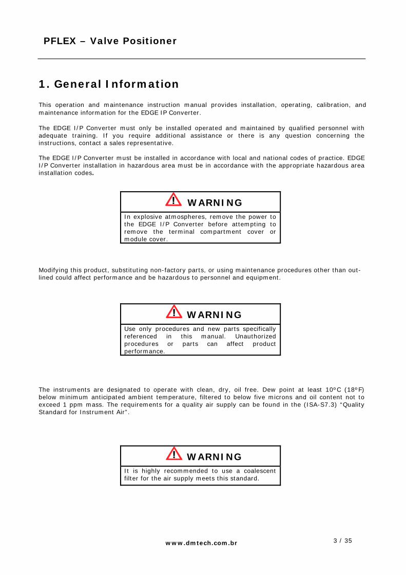
1. General Information This operation and maintenance instruction manual provides installation, operating, calibration, and maintenance information for the EDGE IP Converter. The EDGE I/P Converter must only be installed operated and maintained by qualified personnel with adequate training. If you require additional assistance or there is any question concerning the instructions, contact a sales representative. The EDGE I/P Converter must be installed in accordance with local and national codes of practice. EDGE I/P Converter installation in hazardous area must be in accordance with the appropriate hazardous area installation codes.
WARNING
In explosive atmospheres, remove the power to the EDGE I/P Converter before attempting to remove the terminal compartment cover or module cover.
Modifying this product, substituting non-factory parts, or using maintenance procedures other than out-lined could affect performance and be hazardous to personnel and equipment.
WARNING
Use only procedures and new parts specifically referenced in this manual. Unauthorized procedures or parts can affect product performance.
The instruments are designated to operate with clean, dry, oil free. Dew point at least 10ºC (18ºF) below minimum anticipated ambient temperature, filtered to below five microns and oil content not to exceed 1 ppm mass. The requirements for a quality air supply can be found in the (ISA-S7.3) “Quality Standard for Instrument Air”.
WARNING
It is highly recommended to use a coalescent filter for the air supply meets this standard.

4 / 35
PFLEX – Valve Positioner
www.dmtech.com.br
Figure 1 shows how PFLEX can be assembled using signal adaptor to receive 3- 15 psig or I/P converter to receive 4 to 20 mA used as control signal.
Figure 1 – PFLEX Pneumatic & Electro-Pneumatic Positioner The PFLEX Positioner for rotary version showed on figure 2, it is compliance as standard ISO F05 to assemblies according rules VDI/VDE 3845. Pneumatic connections: 1/4-18 NPT female.
Figure 2 – PFLEX – Rotary Actuators

5 / 35
PFLEX – Valve Positioner
www.dmtech.com.br
Figure 3 shows pneumatic positioner for linear actuators. This device is designated for mounting on linear actuators. All pneumatic connections are 1/4-18 NPT - females.
Figure 3 – PFLEX for Linear actuators
2. Description The PFLEX valve positioner, showed on figure 4, is a Pneumatic Positioner or Electro-Pneumatic Positioner CAM characterized it has high dynamic performance and positioning precision and versatility. This versatile project plus high quality of the construction allows PFLEX to be used under severe industrial conditions. It is constructed to withstand harsh industrial environments without any loss of accuracy. It can be modified in the field from pneumatic to electro-pneumatic positioner just replacing gauge meter block by EDGE I/P converter. The converter is assembled directly on the positioner block allowing a simple conversion.

6 / 35
PFLEX – Valve Positioner
www.dmtech.com.br
Figure 4 – PFLEX –Modular Constructions
7 / 35
PFLEX – Valve Positioner
www.dmtech.com.br
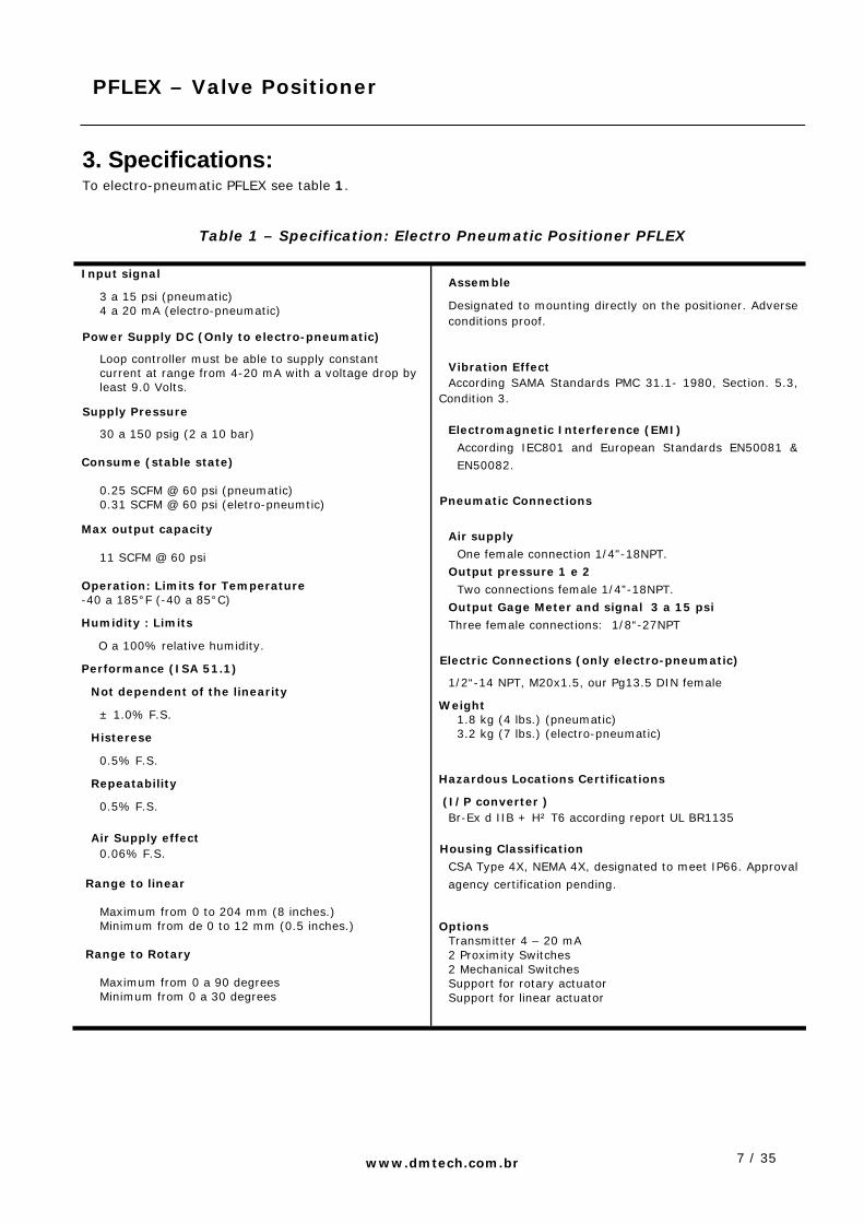
3. Specifications: To electro-pneumatic PFLEX see table 1.
Table 1 – Specification: Electro Pneumatic Positioner PFLEX
Input signal
3 a 15 psi (pneumatic) 4 a 20 mA (electro-pneumatic)
Power Supply DC (Only to electro-pneumatic)
Loop controller must be able to supply constant current at range from 4-20 mA with a voltage drop by least 9.0 Volts.
Supply Pressure
30 a 150 psig (2 a 10 bar)
Consume (stable state) 0.25 SCFM @ 60 psi (pneumatic) 0.31 SCFM @ 60 psi (eletro-pneumtic)
Max output capacity 11 SCFM @ 60 psi
Operation: Limits for Temperature -40 a 185°F (-40 a 85°C)
Humidity : Limits
O a 100% relative humidity.
Performance (ISA 51.1)
Not dependent of the linearity
± 1.0% F.S.
Histerese
0.5% F.S.
Repeatability
0.5% F.S. Air Supply effect
0.06% F.S.
Range to linear Maximum from 0 to 204 mm (8 inches.) Minimum from de 0 to 12 mm (0.5 inches.)
Range to Rotary Maximum from 0 a 90 degrees Minimum from 0 a 30 degrees
Assemble
Designated to mounting directly on the positioner. Adverse conditions proof.
Vibration Effect According SAMA Standards PMC 31.1- 1980, Section. 5.3,
Condition 3. Electromagnetic Interference (EMI)
According IEC801 and European Standards EN50081 &
EN50082.
Pneumatic Connections
Air supply
One female connection 1/4"-18NPT.
Output pressure 1 e 2
Two connections female 1/4”-18NPT.
Output Gage Meter and signal 3 a 15 psi
Three female connections: 1/8“-27NPT
Electric Connections (only electro-pneumatic)
1/2“-14 NPT, M20x1.5, our Pg13.5 DIN female
Weight 1.8 kg (4 lbs.) (pneumatic) 3.2 kg (7 lbs.) (electro-pneumatic)
Hazardous Locations Certifications
(I/P converter ) Br-Ex d IIB + H² T6 according report UL BR1135
Housing Classification
CSA Type 4X, NEMA 4X, designated to meet IP66. Approval
agency certification pending.
Options Transmitter 4 – 20 mA 2 Proximity Switches 2 Mechanical Switches Support for rotary actuator Support for linear actuator

8 / 35
PFLEX – Valve Positioner
www.dmtech.com.br
4. Installation The EDGE I/P Converter must only be maintained by qualified personnel with adequate training. If you require additional assistance or there is any question concerning the instructions, contact a sales Representative. Industrial environments often contain particulate, liquid, and gaseous contaminants. Extended exposure to these contaminants may result in equipment malfunctions. Identify contaminants and implement methods to reduce their presence. The EDGE I/P Converter must be installed in accordance with local and national codes of practice. EDGE I/P Converter installation in hazardous area must be in accordance with the appropriate hazardous area installation codes.
WARNING In explosive atmospheres, remove the power to the EDGE I/P Converter before attempting to remove the terminal compartment cover or module cover.
4.1 Mounting
When acquired with a control valve, the positioner it will installed by contractor, If acquired by end user it
will be necessary to buy a assemble mounting kit to fix it on the actuator.
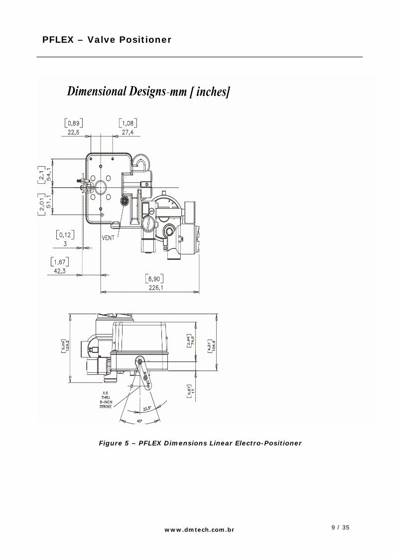
Figure 5 shows dimensions for PFLEX positioner (linear actuators).
Figure 6 shows dimensions for PFLEX positioner (rotary actuators).
9 / 35
PFLEX – Valve Positioner
www.dmtech.com.br
Figure 5 – PFLEX Dimensions Linear Electro-Positioner

10 / 35
PFLEX – Valve Positioner
www.dmtech.com.br
Figure 6 – PFLEX Dimensional Electro-Pneumatic Rotary
11 / 35
PFLEX – Valve Positioner
www.dmtech.com.br
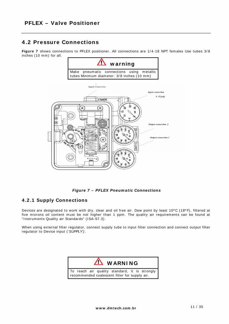
4.2 Pressure Connections
Figure 7 shows connections to PFLEX positioner. All connections are 1/4-18 NPT females Use tubes 3/8 inches (10 mm) for all.
warning Make pneumatic connections using metallic tubes Minimum diameter: 3/8 inches (10 mm)
Figure 7 – PFLEX Pneumatic Connections
4.2.1 Supply Connections Devices are designated to work with dry, clear and oil free air. Dew point by least 10ºC (18ºF), filtered at five microns oil content must be not higher than 1 ppm. The quality air requirements can be found at “Instruments Quality air Standards” (ISA-S7.3). When using external filter regulator, connect supply tube to input filter connection and connect output filter regulator to Device input (‘SUPPLY’).
WARNING To reach air quality standard, it is strongly recommended coalescent filter for supply air.
12 / 35
PFLEX – Valve Positioner
www.dmtech.com.br
ADVISE Without input current the Output 1 will go to zero and the Output 2 will go to maximum supply pressure.
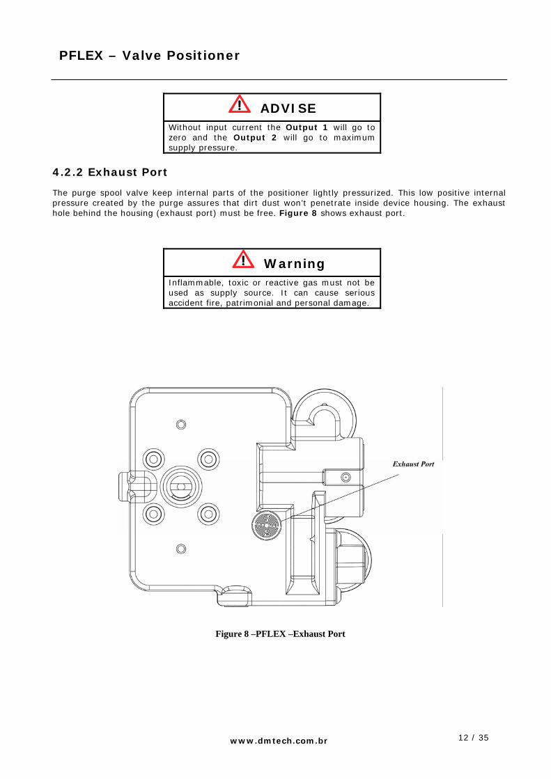
4.2.2 Exhaust Port
The purge spool valve keep internal parts of the positioner lightly pressurized. This low positive internal pressure created by the purge assures that dirt dust won’t penetrate inside device housing. The exhaust hole behind the housing (exhaust port) must be free. Figure 8 shows exhaust port.
Warning Inflammable, toxic or reactive gas must not be used as supply source. It can cause serious accident fire, patrimonial and personal damage.
Figure 8 –PFLEX –Exhaust Port
13 / 35
PFLEX – Valve Positioner
www.dmtech.com.br
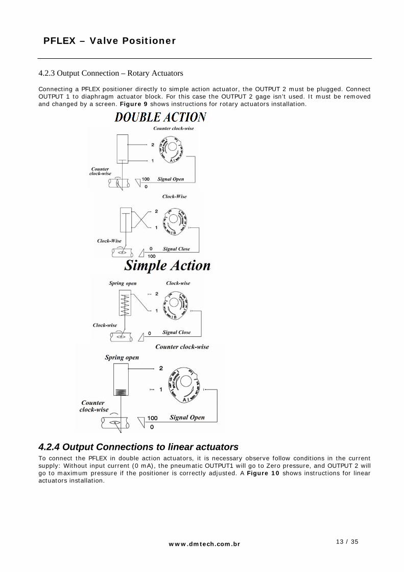
4.2.3 Output Connection – Rotary Actuators Connecting a PFLEX positioner directly to simple action actuator, the OUTPUT 2 must be plugged. Connect OUTPUT 1 to diaphragm actuator block. For this case the OUTPUT 2 gage isn’t used. It must be removed and changed by a screen. Figure 9 shows instructions for rotary actuators installation.
4.2.4 Output Connections to linear actuators To connect the PFLEX in double action actuators, it is necessary observe follow conditions in the current supply: Without input current (0 mA), the pneumatic OUTPUT1 will go to Zero pressure, and OUTPUT 2 will go to maximum pressure if the positioner is correctly adjusted. A Figure 10 shows instructions for linear actuators installation.

14 / 35
PFLEX – Valve Positioner
www.dmtech.com.br
Figure10 –PFLEX – Linear Actuators installations

15 / 35
PFLEX – Valve Positioner
www.dmtech.com.br
4.3 Electric Connections The signal wiring comes to terminal compartment through 1/2-14 NPT connection, M20x1.5 or Pg13.5 DIN, showed in the figure 11. This tube must be sealed. Electric connections are plugged on terminal blocks, when solicited; a special block for grounding must be supplied. See figure11 as example, this unit has an external grounding. Connect positive signal to terminal block indicated with + (positive) and – (negative) as showed in the figure 11. Don’t connect the device directly to a voltage supply; this will damage irreversibly the electronic board. This connection requires a current supply 4-20 mA.
WARNING
Current loop must to be able to supply current 4-20 mA with a voltage range not inferior than 9, 0 Volts.
Figure 11 – EDGE – Electric Connections

16 / 35
PFLEX – Valve Positioner
www.dmtech.com.br
4.4 CAM 4.2.1 CAM Adjust for Rotary Actuators The standard CAM for PFLEX at rotary actuators is angular 90º characterized to linear action and mounted to counter clock-wise position. The Figure 12 shows adjust to install the CAM for rotary actuators.
Figure 12 – PFLEX – CAM Adjust for Rotary Positioner Use following steps to adjust CAM for rotary positioners: 1. It removes coverage and position indicator. 2. Loosen the screw 1 and rotate the nut of the CAM 2 to the CAM to rotate freely. 3. Rotate the actuator for the initial position of turn in 0% of the input signal. 4. Set up the CAM 3 as the indication on the side wanted in agreement with the opening of the actuator and adjustment the CAM 3 as suitable in the illustration 12, guaranteeing that the roller is always in contact with the surface of work of the CAM. 5. Only after the verification if the screw 1 is accordingly the suitable measure in the illustration 12, lock the nut of the CAM 2.
17 / 35
PFLEX – Valve Positioner
www.dmtech.com.br
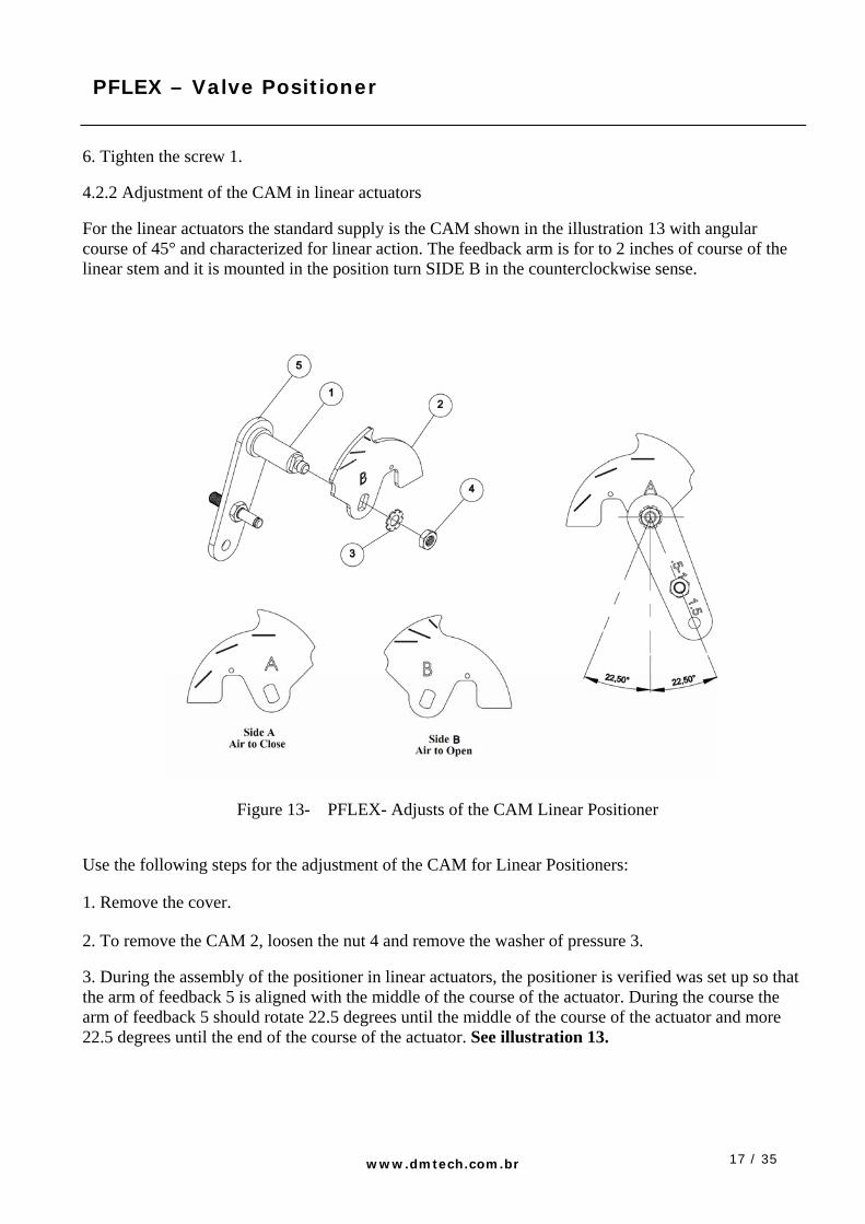
6. Tighten the screw 1. 4.2.2 Adjustment of the CAM in linear actuators For the linear actuators the standard supply is the CAM shown in the illustration 13 with angular course of 45° and characterized for linear action. The feedback arm is for to 2 inches of course of the linear stem and it is mounted in the position turn SIDE B in the counterclockwise sense.
Figure 13- PFLEX- Adjusts of the CAM Linear Positioner
Use the following steps for the adjustment of the CAM for Linear Positioners: 1. Remove the cover. 2. To remove the CAM 2, loosen the nut 4 and remove the washer of pressure 3. 3. During the assembly of the positioner in linear actuators, the positioner is verified was set up so that the arm of feedback 5 is aligned with the middle of the course of the actuator. During the course the arm of feedback 5 should rotate 22.5 degrees until the middle of the course of the actuator and more 22.5 degrees until the end of the course of the actuator. See illustration 13.

18 / 35
PFLEX – Valve Positioner
www.dmtech.com.br
4. Set up the CAM 2 as the indication on the side wanted in agreement with the opening of the actuator, to see illustration 13, guaranteeing that the roller is always in contact with the surface of work of the CAM 2. 5. Set up the washer of pressure 3 and press the nut 4.
5. Calibration Before the delivery, all of the positioners PFLEX are tested and inspected for 0-100% of the range. 5.1 Calibrations of the zero and span Use the following procedures to obtain the calibration of the zero: 1. For calibration zero, supply 0% of input signal for the positioner and await the stabilization of the position of the valve. 2. Adjust the zero position with the help of a suitable in accordance screwdriver in the illustration 14. 3. Supply a complete loop of the input signal, fed with 0%, 100% and returning for 0% for verification of the course of the stem and for warranty that the zero was calibrated properly. 4. For calibration span, maintain the signal of input 0% 5. Adjustment the span rotating the nut of adjustment of the suitable in accordance span in the illustration 14. 6. If necessary, execute the steps from 1 to 3 again for the perfect performance of the positioning of the valve in 0%. 7. Supply a complete loop of the input signal, fed with 0%, 100% and returning for 0% for verification of the course of the stem and for warranty that the zero was calibrated properly. If necessary, execute the steps from 5 to 7 again for the perfect performance of the positioning of the valve in 100%.
19 / 35
PFLEX – Valve Positioner
www.dmtech.com.br
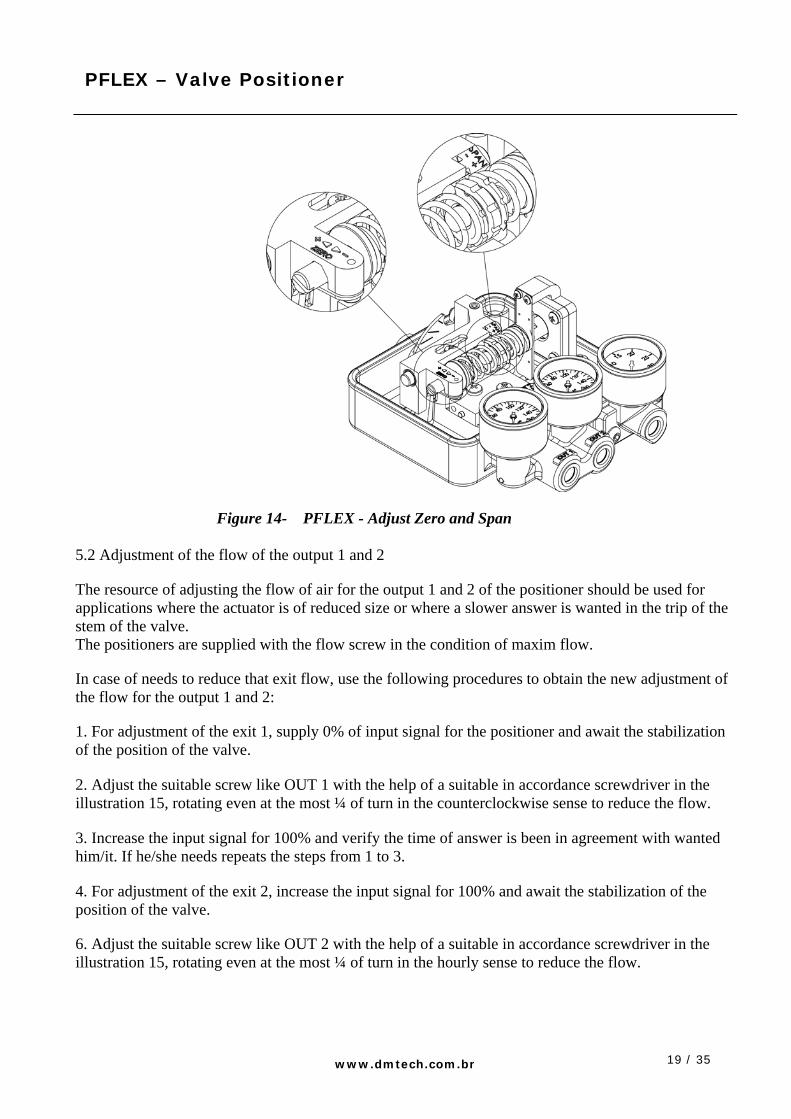
Figure 14- PFLEX - Adjust Zero and Span
5.2 Adjustment of the flow of the output 1 and 2 The resource of adjusting the flow of air for the output 1 and 2 of the positioner should be used for applications where the actuator is of reduced size or where a slower answer is wanted in the trip of the stem of the valve. The positioners are supplied with the flow screw in the condition of maxim flow. In case of needs to reduce that exit flow, use the following procedures to obtain the new adjustment of the flow for the output 1 and 2: 1. For adjustment of the exit 1, supply 0% of input signal for the positioner and await the stabilization of the position of the valve. 2. Adjust the suitable screw like OUT 1 with the help of a suitable in accordance screwdriver in the illustration 15, rotating even at the most ¼ of turn in the counterclockwise sense to reduce the flow. 3. Increase the input signal for 100% and verify the time of answer is been in agreement with wanted him/it. If he/she needs repeats the steps from 1 to 3. 4. For adjustment of the exit 2, increase the input signal for 100% and await the stabilization of the position of the valve. 6. Adjust the suitable screw like OUT 2 with the help of a suitable in accordance screwdriver in the illustration 15, rotating even at the most ¼ of turn in the hourly sense to reduce the flow.

20 / 35
PFLEX – Valve Positioner
www.dmtech.com.br
7. Decrease the input signal to 0% and verify the time of answer is been in agreement with wanted him/it. If he/she needs repeats the steps from 4 to 7.
Figure 15- Adjusts of the flow (output 1 and 2) 6. Operation
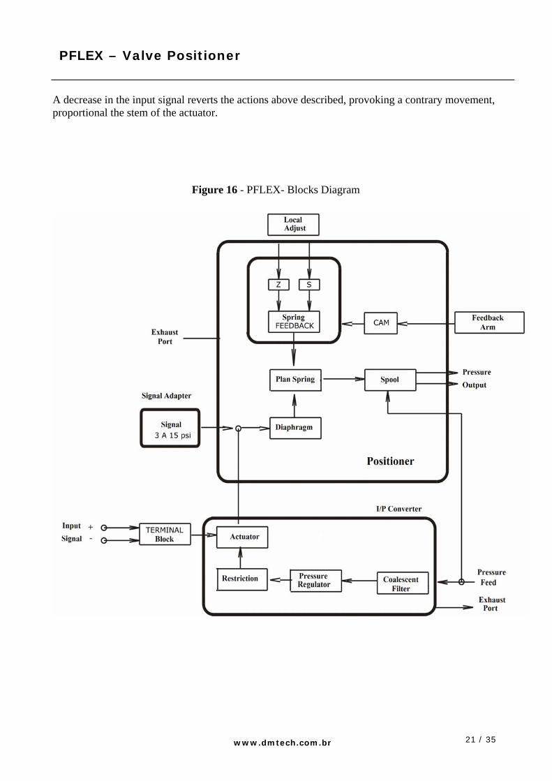
The diagram of blocks of Figures 16 describes the positioner PFLEX with the options of feeding of the input signal through a signal adapter or of a converter me me /P. A better detail about the operation of the converter I/P is described in the manual of installation instruction and maintenance of the same. The positioner PFLEX is a balance instrument among two forces; a proportional one to the input signal and the other proportional one to the position of the stem of the actuator. An increase in the input signal provokes the displacement of the diaphragm, pushing the spring glides against the feedback spring. In the displacement of the spring it glides, the spool is also moved, supplying air for the exit 1 of the positioner that is connected to the input of the actuator. The movement of the actuator, after the reception of the air of supply of the spool, it is transmitted from turn to the positioner through the feedback stem and of the CAM resulting in a larger force on the feedback spring. The stem of the actuator continues the movement until that the force of the feedback spring increases enough to counterbalance the force generated by the diaphragm with the input signal, decreasing the passage of air to the actuator. After the actuator to have reached the wanted position, the force that is on the feedback spring wills is same the force generated by the diaphragm. The spring glides balance position returns without any flow of air for the actuator, until that it happens a new change of input signal.
21 / 35
PFLEX – Valve Positioner
www.dmtech.com.br
A decrease in the input signal reverts the actions above described, provoking a contrary movement, proportional the stem of the actuator.
Figure 16 - PFLEX- Blocks Diagram

22 / 35
PFLEX – Valve Positioner
www.dmtech.com.br
7. Troubleshooting A list of location of problems for the positioner PFLEX is founded in the table 2.
Table 2-Trhoubleshooting
PROBLEM POSSIBLE CAUSE SUGGESTED ACTION Supply of insufficient air Verify the input pressure Damaged diaphragm Substitute the group diaphragm Valve spool is arrested Clean the valve spool
Instrument doesn't answer to the input signal
Installation of the piping between positioner and actuator or position of the wrong CAM
Verify the pneumatic connection between actuator and positioner and correct the position of the CAM.
The actuator reaches the position 100% with a small variation of the input signal
Installation of the piping between positioner and actuator or position of the wrong CAM
Verify the pneumatic connection between actuator and positioner and correct the position of the CAM.
Dirt in the valve spool Clean the valve spool Damaged diaphragm or leaking
Substitute the group diaphragm
Incorrect dimension of the actuator
Increase the supply pressure to the maximum of 150 psi or substitute the actuator
Valve movement with a lot of difficulty, “catching”
Increase the supply pressure to the maximum of 150 psi or substitute the valve
Imprecise positioning
CAM is rotating free in relationship the axis
To execute the procedure of adjustment of the CAM
Dirt in the valve spool Clean the valve spool Incorrect piping of supply air or I filter obstructed regulator
To change the piping of air for the specified or to substitute the filter regulator
Overshooting or reaching the position very slowly
Valve spool is arrested Clean the valve spool
23 / 35
PFLEX – Valve Positioner
www.dmtech.com.br
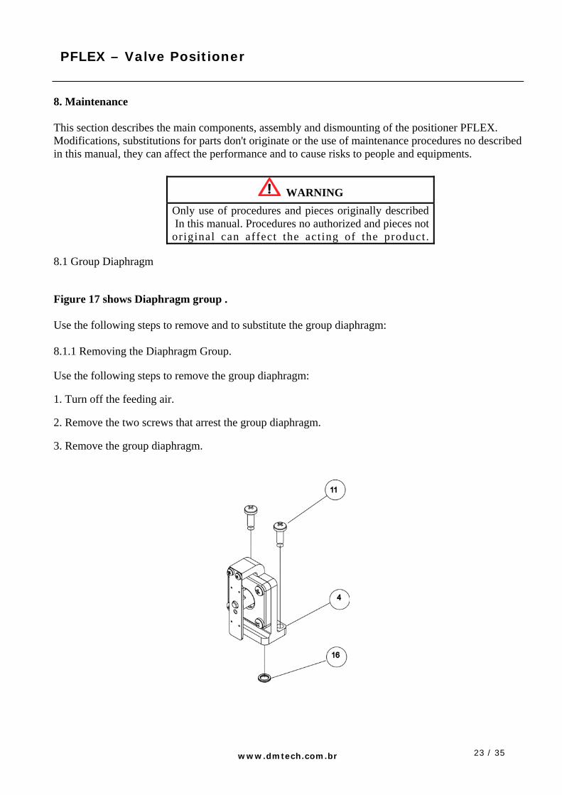
8. Maintenance This section describes the main components, assembly and dismounting of the positioner PFLEX. Modifications, substitutions for parts don't originate or the use of maintenance procedures no described in this manual, they can affect the performance and to cause risks to people and equipments.
WARNING Only use of procedures and pieces originally described In this manual. Procedures no authorized and pieces not original can affect the acting of the product.
8.1 Group Diaphragm Figure 17 shows Diaphragm group . Use the following steps to remove and to substitute the group diaphragm: 8.1.1 Removing the Diaphragm Group. Use the following steps to remove the group diaphragm: 1. Turn off the feeding air. 2. Remove the two screws that arrest the group diaphragm. 3. Remove the group diaphragm.
24 / 35
PFLEX – Valve Positioner
www.dmtech.com.br
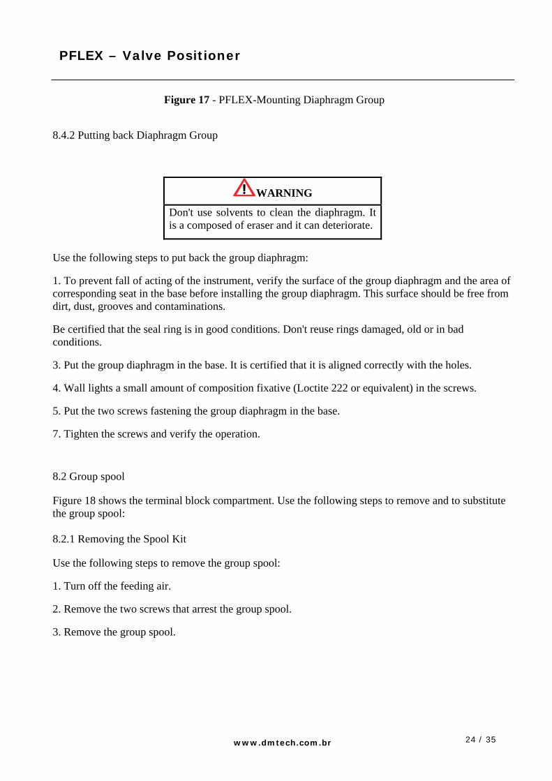
Figure 17 - PFLEX-Mounting Diaphragm Group
8.4.2 Putting back Diaphragm Group
WARNING
Don't use solvents to clean the diaphragm. It is a composed of eraser and it can deteriorate.
Use the following steps to put back the group diaphragm: 1. To prevent fall of acting of the instrument, verify the surface of the group diaphragm and the area of corresponding seat in the base before installing the group diaphragm. This surface should be free from dirt, dust, grooves and contaminations. Be certified that the seal ring is in good conditions. Don't reuse rings damaged, old or in bad conditions. 3. Put the group diaphragm in the base. It is certified that it is aligned correctly with the holes. 4. Wall lights a small amount of composition fixative (Loctite 222 or equivalent) in the screws. 5. Put the two screws fastening the group diaphragm in the base. 7. Tighten the screws and verify the operation.
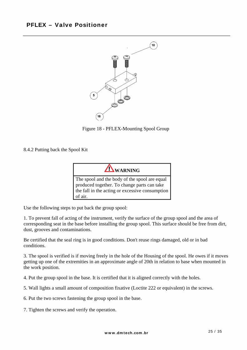
8.2 Group spool Figure 18 shows the terminal block compartment. Use the following steps to remove and to substitute the group spool: 8.2.1 Removing the Spool Kit Use the following steps to remove the group spool: 1. Turn off the feeding air. 2. Remove the two screws that arrest the group spool. 3. Remove the group spool.
25 / 35
PFLEX – Valve Positioner
www.dmtech.com.br
Figure 18 - PFLEX-Mounting Spool Group
8.4.2 Putting back the Spool Kit
WARNING
The spool and the body of the spool are equal produced together. To change parts can take the fall in the acting or excessive consumption of air.
Use the following steps to put back the group spool: 1. To prevent fall of acting of the instrument, verify the surface of the group spool and the area of corresponding seat in the base before installing the group spool. This surface should be free from dirt, dust, grooves and contaminations. Be certified that the seal ring is in good conditions. Don't reuse rings damaged, old or in bad conditions. 3. The spool is verified is if moving freely in the hole of the Housing of the spool. He owes if it moves getting up one of the extremities in an approximate angle of 20th in relation to base when mounted in the work position. 4. Put the group spool in the base. It is certified that it is aligned correctly with the holes. 5. Wall lights a small amount of composition fixative (Loctite 222 or equivalent) in the screws. 6. Put the two screws fastening the group spool in the base. 7. Tighten the screws and verify the operation.
26 / 35
PFLEX – Valve Positioner
www.dmtech.com.br
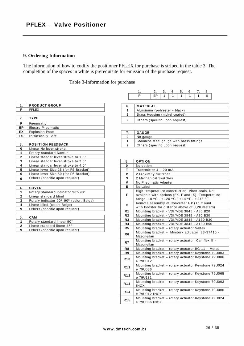
9. Ordering Information The information of how to codify the positioner PFLEX for purchase is striped in the table 3. The completion of the spaces in white is prerequisite for emission of the purchase request.
Table 3-Information for purchase
1. PRODUCT GROUP P PFLEX
2. TYPE
P Pneumatic EP Electro Pneumatic EX Explosion Proof IS Intrinsically Safe
3. POSITION FEEDBACK 0 Linear No lever stroke 1 Rotary standard Namur 2 Linear standar lever stroke to 1.5” 3 Linear standar lever stroke to 2.0” 4 Linear standar lever stroke to 4.0” 5 Linear lever Size 25 (for R5 Bracket) 6 Linear lever Size 50 (for R5 Bracket) 9 Others (specific upon request)
4. COVER 1 Rotary standard indicator 90°-90° 2 Linear standard blind 3 Rotary indicator 90º-90º (color: Beige) 4 Linear blind (color: Beige) 9 Others (specific upon request)
5. CAM 1 Rotary standard linear 90° 2 Linear standard linear 45° 9 Others (specific upon request)
1. 2. 3. 4. 5. 6. 7. 8. P EP 1 1 1 1 1 0
6. MATERIAL 1 Aluminum (polyester - black) 2 Brass Housing (nickel coated)
9 Others (specific upon request)
7. GAUGE 0 No gauge 1 Stainless steel gauge with brass fittings 9 Others (specific upon request)
8. OPTION 0 No option T Transmitter 4 – 20 mA P 2 Proximity Switches S 2 Mechanical Switches V No Pneumatic Adapter E No Label
F High temperature construction. Viton seals. Not available with options (EX, P and IS). Temperature range -10 ºC - +120 ºC / +14 ºF - +248 ºF
G Remote assembly of Converter I/P (To mount with Booster for distance above of 0,20 meters)
R1 Mounting bracket - VDI/VDE 3845 - A80 B20 R2 Mounting bracket - VDI/VDE 3845 - A80 B30 R3 Mounting bracket - VDI/VDE 3845 - A130 B30 R4 Mounting bracket - VDI/VDE 3845 - A130 B50 R5 Mounting bracket – rotary actuator Valtek
R6 Mounting bracket – Minitork actuator 33-37410 - Masoneilan
R7 Mounting bracket – rotary actuator Camflex II - Masoneilan
R8 Mounting bracket – rotary actuator BC-11 – Metso R9 Mounting bracket – rotary actuator Keystone 79U003
R10 Mounting bracket – rotary actuator Keystone 79U006 e 79U012
R11 Mounting bracket – rotary actuator Keystone 79U024 e 79U036
R12 Mounting bracket – rotary actuator Keystone 79U065 e 79U181
R13 Mounting bracket – rotary actuator Keystone 79U003 INOX
R14 Mounting bracket – rotary actuator Keystone 79U006 e 79U012 INOX
R15 Mounting bracket – rotary actuator Keystone 79U024 e 79U036 INOX
27 / 35
PFLEX – Valve Positioner
www.dmtech.com.br
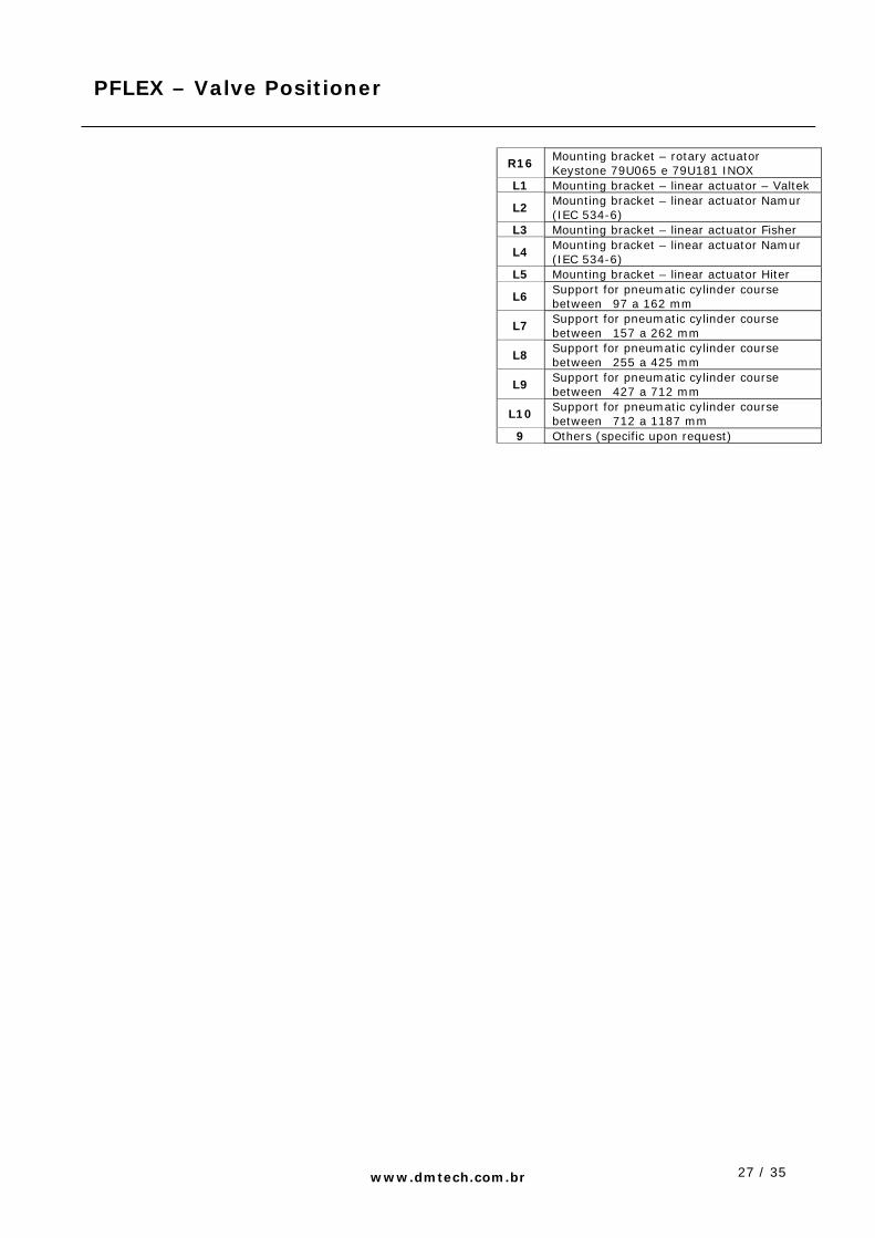
R16 Mounting bracket – rotary actuator Keystone 79U065 e 79U181 INOX
L1 Mounting bracket – linear actuator – Valtek
L2 Mounting bracket – linear actuator Namur (IEC 534-6)
L3 Mounting bracket – linear actuator Fisher
L4 Mounting bracket – linear actuator Namur (IEC 534-6)
L5 Mounting bracket – linear actuator Hiter
L6 Support for pneumatic cylinder course between 97 a 162 mm
L7 Support for pneumatic cylinder course between 157 a 262 mm
L8 Support for pneumatic cylinder course between 255 a 425 mm
L9 Support for pneumatic cylinder course between 427 a 712 mm
L10 Support for pneumatic cylinder course between 712 a 1187 mm
9 Others (specific upon request)
28 / 35
PFLEX – Valve Positioner
www.dmtech.com.br
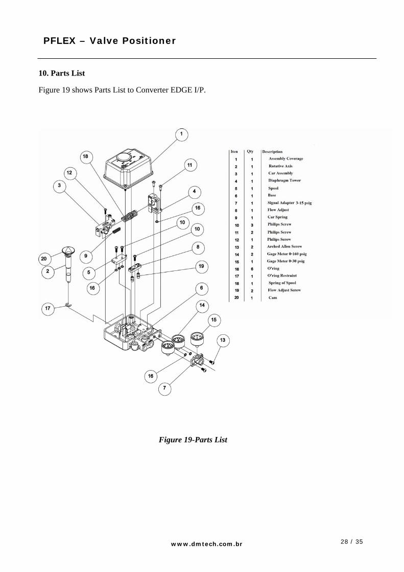
10. Parts List Figure 19 shows Parts List to Converter EDGE I/P.
Figure 19-Parts List

29 / 35
PFLEX – Valve Positioner
www.dmtech.com.br
11. Spare Parts List The spare parts for PFLEX positioners are striped in the table 4. When it specifies a request of purchase of spare parts, refer to the code with 9 digits of each kit as in the list to proceed:
Table 4-Spare Parts list
Description Code Drawing Item Number
Qtd
Gauge box stainless steel with connection in brass (0-30 psi)
109-286-503
15 1
Gauge box stainless steel with connection in brass (0-160 psi)
115-384-200
14 1
11 2
4 1
Kit United Diaphragm 115-384-201
16 1
10 2
5 1
Kit Spool Valve 115-384-202
16 3
Linear CAM 90° - Pattern Rotary Actuator
115-384-203
20 1
Linear CAM 45° - Pattern Linear Actuator
115-384-204
20 1
30 / 35
PFLEX – Valve Positioner
www.dmtech.com.br
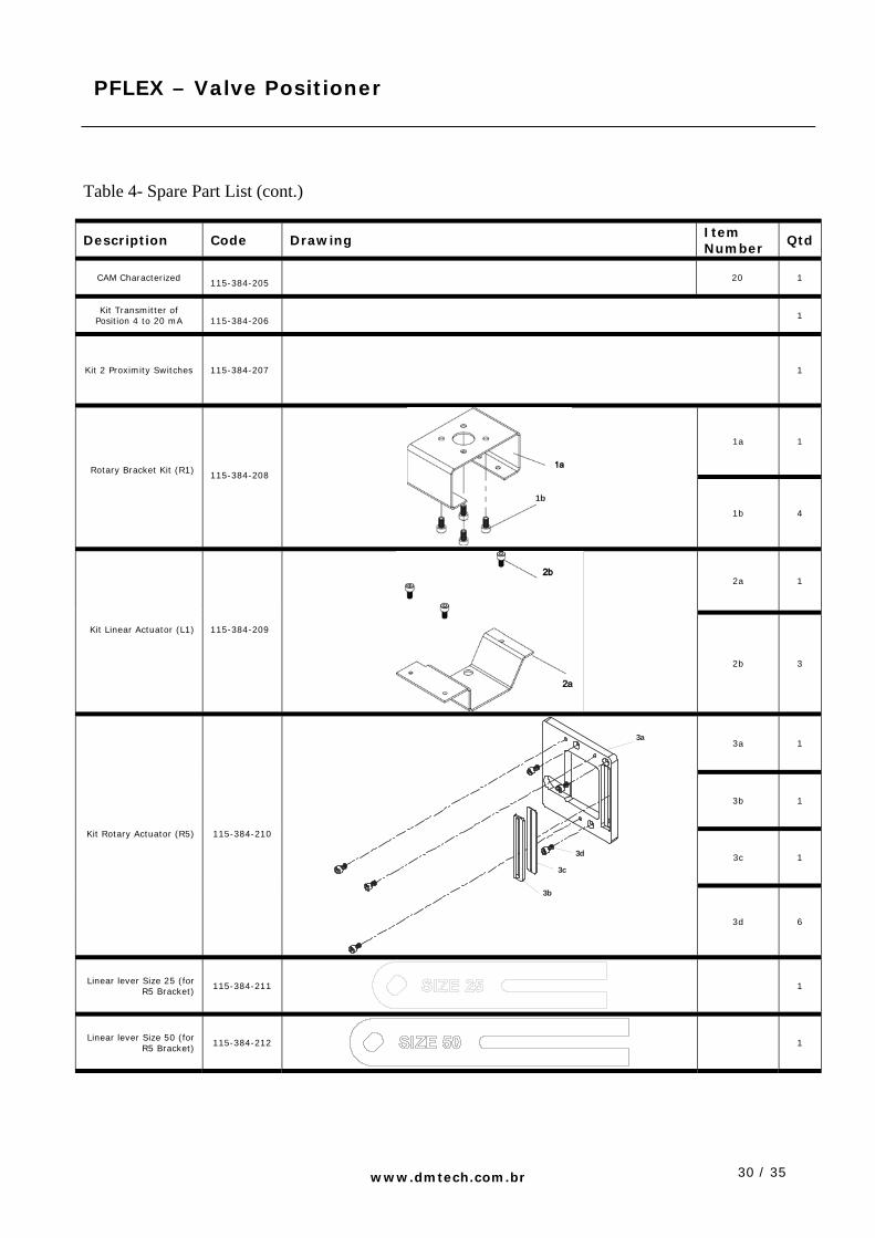
Table 4- Spare Part List (cont.)
Description Code Drawing Item Number
Qtd
CAM Characterized 115-384-205
20 1
Kit Transmitter of Position 4 to 20 mA
115-384-206 1
Kit 2 Proximity Switches 115-384-207 1
1a 1
Rotary Bracket Kit (R1)
115-384-208
1b
1b 4
2a
1
Kit Linear Actuator (L1) 115-384-209
2b 3
3a
1
3b 1
3c 1
Kit Rotary Actuator (R5) 115-384-210
3a
3c
3d
3b
3d 6
Linear lever Size 25 (for R5 Bracket)
115-384-211
1
Linear lever Size 50 (for R5 Bracket)
115-384-212
1

31 / 35
PFLEX – Valve Positioner
www.dmtech.com.br
4ª 1
4b 1 Kit Linear lever stroke to
1.5” 115-384-213
4a
4b
4c
4c 2
5ª 1
5b 1 Kit Linear lever stroke to
2” 115-384-214
5a
5b
5c
5c 2
6ª 1
6b 1 Kit Linear lever stroke to
4” 115-384-215
6a
6b
6c
6c 2
7a 1
7b 1
7c 2
7d 1
Kit Pneumatic Adapter 3–15 psi
Kit Pneumatic Adapter 3–15 psi No gauge
115-384-216
115-384-221
7a
7b
7c
7d
7e
7e 1
32 / 35
PFLEX – Valve Positioner
www.dmtech.com.br
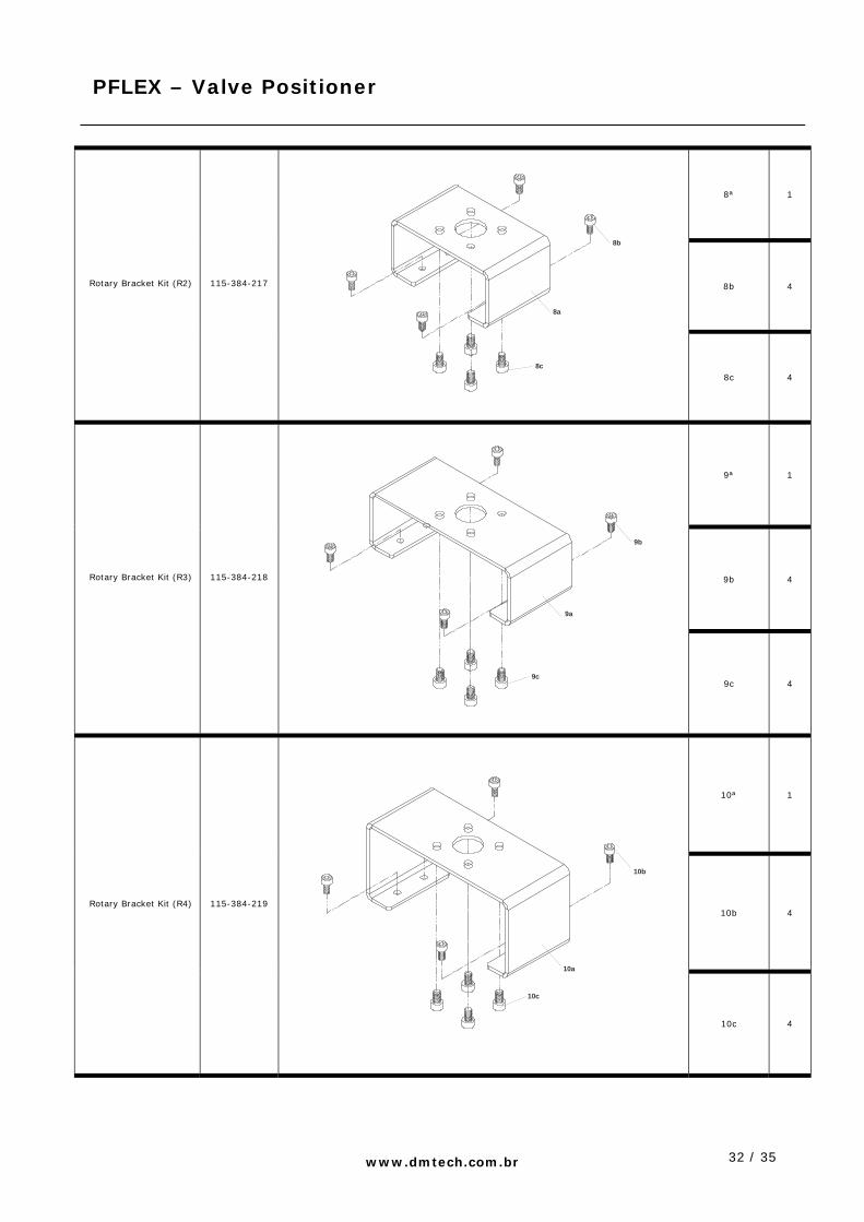
8ª 1
8b 4 Rotary Bracket Kit (R2) 115-384-217
8a
8b
8c
8c 4
9ª 1
9b 4 Rotary Bracket Kit (R3) 115-384-218
9c
9a
9b
9c 4
10ª 1
10b 4 Rotary Bracket Kit (R4) 115-384-219
10c
10b
10a
10c 4

33 / 35
PFLEX – Valve Positioner
www.dmtech.com.br
Linear Bracket Kit (L2) 115-384-220
Rotary Bracket Kit Minitork 33-37410 -
Masoneilan (R6) 115-384-222
Rotary Bracket Kit Camflex II- Masoneilan
(R7) 115-384-223
Rotary Bracket Kit BC-11 – Metso (R8)
115-384-224
Linear Bracket Kit (L3) Fisher
115-384-225
Linear Bracket Kit (L4) Namur (IEC 534-6)
115-384-226
Linear Bracket Kit (L5) Hiter
115-384-227

34 / 35
PFLEX – Valve Positioner
www.dmtech.com.br
Rotary Bracket Kit (R9) Keystone 79U003 115-384-228
Rotary Bracket Kit (R10) Keystone 79U006 e
79U012 115-384-229
Rotary Bracket Kit (R11) Keystone 79U024 e
79U036 115-384-230
Rotary Bracket Kit (R12) Keystone 79U065 e
79U181 115-384-231
Rotary Bracket Kit (R13) Keystone 79U003 INOX 115-384-232
Rotary Bracket Kit (R14) Keystone 79U006 e
79U012 INOX 115-384-233
Rotary Bracket Kit (R15) Keystone 79U024 e
79U036 INOX 115-384-234
Rotary Bracket Kit (R16) Keystone 79U065 e
79U181 INOX 115-384-235
Switchbox - 2 mechanical 115-384-236
35 / 35
PFLEX – Valve Positioner
www.dmtech.com.br
12. Returning for Repair Returning equipment for repair, during the warranty period or no, follow the following steps: 1. Always mention the serial number of the positioner PFLEX. 2. Inform the reasons for return (for instance: mistake code, symptom of the ambient flaw of the installation etc.) 3. The warranty will be annulled if the repair be executed by personnel no authorized for the Department of Services of DMTECH.
13. Warranty DMTECH guarantees the equipments and repairs executed and sold under his mark as free from defects of materials and of manufacture under normal conditions of service and with appropriate use. The warranty is applied for any part of the equipment here described and sold by DMTECH for defect of materials and manufacture within 12 months of the issue date (DMTECH factory).he repairs will be accomplished at DMTECH facilities and the equipments should be returned with freight previously paid. The warranty will be discontinued if the company finds use defect or bad operation for the buyer, their employees or other. DMTECH won't assume warranty for bad use on the part of the buyer.