Embed Size (px)
Citation preview

kÉï=~ë=çÑW= MPKOMMU
rp^
pfoli~ëÉêléÉê~íáåÖ=fåëíêìÅíáçåë

60 88 921 D 34852 D 3485.201.02.10.02 03.2008
No part of this publication may be reproduced, transmitted, stored or translated into any language, in any form or through any electronic, magnetic, optical, chemical, manual, physical device or other means, without the prior written consent from Sirona Dental Systems GmbH, Fabrikstrasse 31, 64625 Bensheim, Germany.
Sirona Dental Systems GmbH reserves the right to correct or modify the present document without prior notice.
SIROLaser is manufactured in compliance with the provisions of Council Directive 93/42/EEC concerning medical devices (MDD). Its compliance is based on the following standards: IEC 60601-1: 1998, IEC 60601-1/A2: 1998 and IEC 60601-2-22: 1997.0123
Index
båÖäáëÜ
båÖäáëÜ
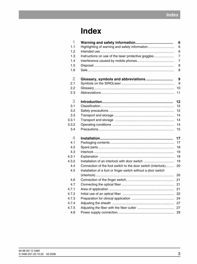
Index1 Warning and safety information..................................... 6
1.1 Highlighting of warning and safety information ............................ 61.2 Intended use ................................................................................ 61.3 Instructions on use of the laser protective goggles...................... 71.4 Interference caused by mobile phones........................................ 71.5 Disposal ....................................................................................... 81.6 Sale.............................................................................................. 8
2 Glossary, symbols and abbreviations........................... 92.1 Symbols on the SIROLaser ......................................................... 92.2 Glossary....................................................................................... 102.3 Abbreviations ............................................................................... 11
3 Introduction...................................................................... 123.1 Classification................................................................................ 123.2 Safety precautions ....................................................................... 123.3 Transport and storage ................................................................. 14
3.3.1 Transport and storage ................................................................ 143.3.2 Operating conditions ................................................................... 14
3.4 Precautions.................................................................................. 15
4 Installation........................................................................ 174.1 Packaging contents ..................................................................... 174.2 Spare parts .................................................................................. 184.3 Interlock ....................................................................................... 19
4.3.1 Explanation ................................................................................. 194.3.2 Installation of an interlock with door switch ................................. 19
4.4 Connection of the foot switch to the door switch (interlock)......... 204.5 Installation of a foot or finger switch without a door switch
(interlock) ..................................................................................... 204.6 Connection of the finger switch.................................................... 214.7 Connecting the optical fiber ......................................................... 21
4.7.1 Area of application ...................................................................... 214.7.2 Initial use of an optical fiber ........................................................ 224.7.3 Preparation for clinical application .............................................. 244.7.4 Adjusting the sheath ................................................................... 274.7.5 Adjusting the fiber with the fiber cutter ........................................ 27
4.8 Power supply connection............................................................. 29
60 88 921 D 3485D 3485.201.02.10.02 03.2008 3

Index
5 Operating Instructions .................................................... 305.1 Warning and error messages ...................................................... 305.2 Switching the laser unit on and off............................................... 325.3 Control panel ............................................................................... 325.4 Electronic access key .................................................................. 325.5 Setting the interface language ..................................................... 335.6 Main menu ................................................................................... 335.7 SURGERY"", "PERIODONTICS" and
"ENDODONTICS" submenus. ..................................................... 355.8 "MANUAL SETTING AREA" submenu ........................................ 375.9 SETUP AREA“” submenu............................................................ 39
6 Indications, contraindications and medical precautions ...................................................................... 40
6.1 Indications.................................................................................... 406.2 List of indications ......................................................................... 40
6.2.1 Examples of treatment risks ....................................................... 406.3 Contraindications ......................................................................... 416.4 Precautions.................................................................................. 41
7 Cleaning and sterilization ............................................... 427.1 Cleaning....................................................................................... 427.2 Disinfection .................................................................................. 437.3 Sterilization .................................................................................. 437.4 Cleaning the laser unit and the finger switch ............................... 44
8 Maintenance and service ................................................ 458.1 Calibration check ......................................................................... 45
8.1.1 Callibration check without an external power meter ................... 458.1.2 Calibration check using an external power meter ....................... 468.1.3 Error message and incorrect parameter values .......................... 47
8.2 Safety checks .............................................................................. 498.3 Maintenance ................................................................................ 498.4 Troubleshooting of simple defects ............................................... 508.5 Technical support, repair and testing........................................... 50
9 Technical data.................................................................. 51
10 Manufacturer's declaration on electromagnetic compatibility .................................................................... 52
10.1 Definitions .................................................................................... 5210.1.1 Emission (electromagnetic) ........................................................ 5210.1.2 Interference immunity ................................................................. 5210.1.3 Immunity level ............................................................................. 52
11 Appendix .......................................................................... 5611.1 Appendix B – Label positions ...................................................... 56
60 88 921 D 34854 D 3485.201.02.10.02 03.2008
60 88 921 D 3485D 3485.201.02.10.02 03.2008 5
List of Figures
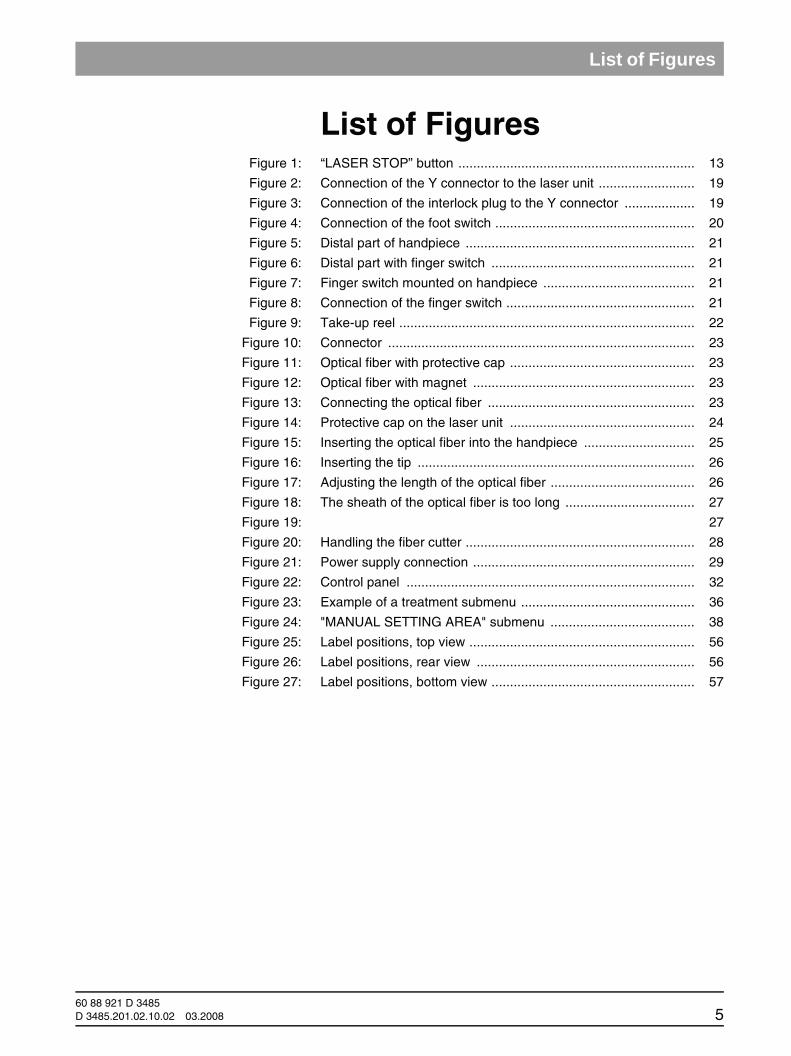
List of FiguresFigure 1: “LASER STOP” button ................................................................ 13
Figure 2: Connection of the Y connector to the laser unit .......................... 19
Figure 3: Connection of the interlock plug to the Y connector ................... 19
Figure 4: Connection of the foot switch ...................................................... 20
Figure 5: Distal part of handpiece .............................................................. 21
Figure 6: Distal part with finger switch ....................................................... 21
Figure 7: Finger switch mounted on handpiece ......................................... 21
Figure 8: Connection of the finger switch ................................................... 21
Figure 9: Take-up reel ................................................................................ 22
Figure 10: Connector ................................................................................... 23
Figure 11: Optical fiber with protective cap .................................................. 23
Figure 12: Optical fiber with magnet ............................................................ 23
Figure 13: Connecting the optical fiber ........................................................ 23
Figure 14: Protective cap on the laser unit .................................................. 24
Figure 15: Inserting the optical fiber into the handpiece .............................. 25
Figure 16: Inserting the tip ........................................................................... 26
Figure 17: Adjusting the length of the optical fiber ....................................... 26
Figure 18: The sheath of the optical fiber is too long ................................... 27
Figure 19: 27
Figure 20: Handling the fiber cutter .............................................................. 28
Figure 21: Power supply connection ............................................................ 29
Figure 22: Control panel .............................................................................. 32
Figure 23: Example of a treatment submenu ............................................... 36
Figure 24: "MANUAL SETTING AREA" submenu ....................................... 38
Figure 25: Label positions, top view ............................................................. 56
Figure 26: Label positions, rear view ........................................................... 56
Figure 27: Label positions, bottom view ....................................................... 57
1 Warning and safety information
1 Warning and safety information
1.1 Highlighting of warning and safety information
To prevent any personal injury or material damage, please observe the warn-ing and safety information provided in the present operating instructions. This information is highlighted as follows:
Offers additional information.
Risk of damaging the laser device.
Immediate danger to life and limb.
This symbol prompts the reader to take action.
This symbol refers to a result.
1.2 Intended use
NOTICE iBefore operating the laser, please read these operating instructions and famil-iarize yourself thoroughly with its functions. The unit must be checked and maintained at regular intervals, as described in the section on Maintenance. If any tissue is unintentionally exposed to irradiation, this may lead to burns. This risk can be reduced by surrounding the target area with moistened sterile drapes or gauze doused in salt. These covering materials must meet the re-quirements of laser surgery. A fume extractor or an in-line filter should be used to remove the drift smoke if possible. The operating personnel should be aware of the fact that the drift smoke constitutes a source of biologically active material. It may contain particles of viable tissue.
NOTICE iThe NOHD (= nominal ocular hazard distance) from the distal end of the opti-cal fiber is 1.5 m.
NOTICE iFor the installation and operation of the SIROLaser, Sirona Dental Systems GmbH requires• compliance with IEC 60825-1 and its amendments as well as• observance of any supplemental national laws and
regulations.
NOTICE i
CAUTION
WARNING
60 88 921 D 34856 D 3485.201.02.10.02 03.2008

1 Warning and safety information
båÖäáëÜ
båÖäáëÜ
NOTICE iSIROLaser can be used for surgery and for coagulating soft tissue in the pa-tient's mouth. The laser may be operated only by qualified personnel. The ap-plicable occupational safety regulations and accident prevention measures and the current operating instructions must be complied with.
NOTICE iUsers are obliged to use only faultless materials, to ensure correct application and to protect themselves, the patient and other persons against hazards.
WARNING This laser device must not be used in areas where an explosion hazard exists or in the vicinity of highly inflammable materials.
WARNING Public legal requirements may include special safety regulations concerning protection against laser radiation. These regulations must be observed.
WARNING Failure to use the settings specified in this manual or perform the actions de-scribed here may lead to a dangerous exposure to radiation.
1.3 Instructions on use of the laser protective goggles
Before using the laser protective goggles, please read and observe the instructions for use provided by the manufacturer and attached to the goggles in the case.
Before using the laser protective goggles, please make sure:
that the laser protective goggles are not damaged,
that the laser protective goggles conform to standard EN 207 with pro-tection level L5,
and that the laser protective goggles are suitable for the correct wave-length (labeled on the goggles).
These instructions apply particularly when using goggles supplied from an outside source that are not included in the scope of delivery of the SIROLaser.
1.4 Interference caused by mobile phones
CAUTION To ensure safe operation of medical electrical equipment, the use of mobile wireless phones in practice or hospital environments must be prohibited.
60 88 921 D 3485D 3485.201.02.10.02 03.2008 7
1 Warning and safety information
1.5 Disposal
If you no longer use your SIROLaser and wish to dispose of it, please be sure to comply with the applicable legal requirements. Please contact your local dental depot or authorized service center prior to disposal of the SIROLaser.
1.6 Sale
CAUTION Federal Law (USA) restricts sale of this device to or on the order of a physi-cian, dentist, or licensed practitioner.
60 88 921 D 34858 D 3485.201.02.10.02 03.2008
2 Glossary, symbols and abbreviations
båÖäáëÜ
båÖäáëÜ
2 Glossary, symbols and abbreviations
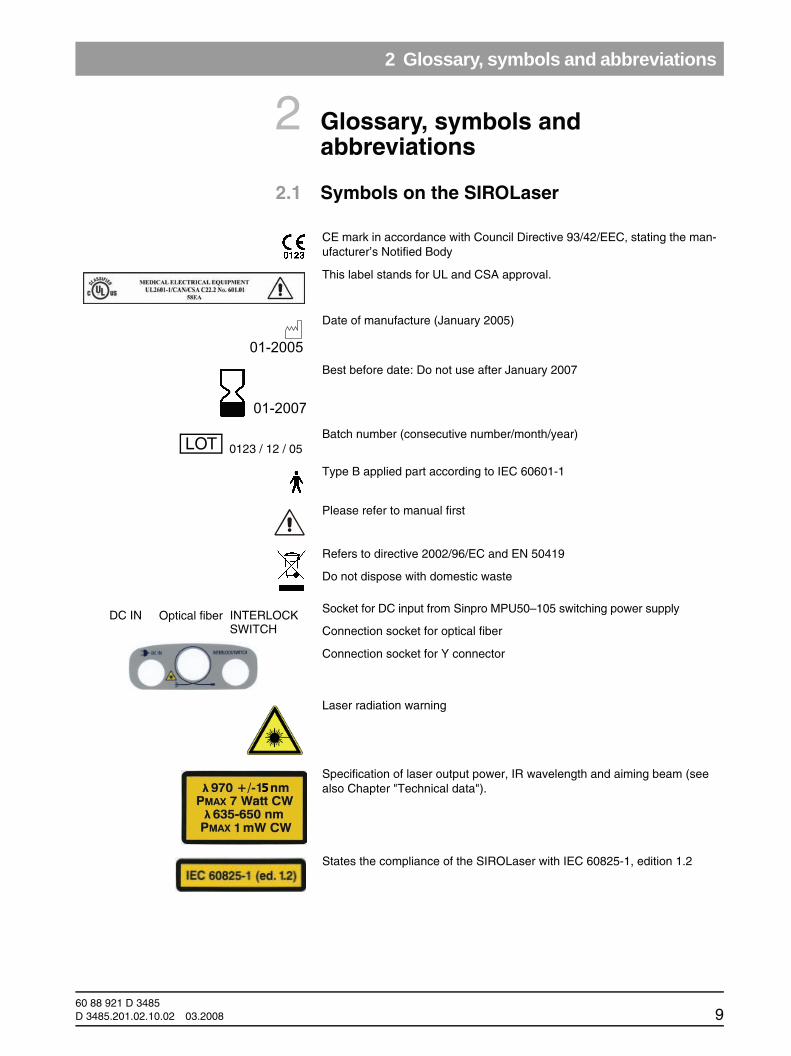
2.1 Symbols on the SIROLaser
CE mark in accordance with Council Directive 93/42/EEC, stating the man-ufacturer’s Notified Body
This label stands for UL and CSA approval.
Date of manufacture (January 2005)
Best before date: Do not use after January 2007
Batch number (consecutive number/month/year)
Type B applied part according to IEC 60601-1
Please refer to manual first
Refers to directive 2002/96/EC and EN 50419
Do not dispose with domestic waste
Socket for DC input from Sinpro MPU50–105 switching power supply
Connection socket for optical fiber
Connection socket for Y connector
Laser radiation warning
Specification of laser output power, IR wavelength and aiming beam (see also Chapter "Technical data").
States the compliance of the SIROLaser with IEC 60825-1, edition 1.2
01-2005
01-2007
0123 / 12 / 05LOT
DC IN INTERLOCKSWITCH
Optical fiber
60 88 921 D 3485D 3485.201.02.10.02 03.2008 9
2 Glossary, symbols and abbreviations
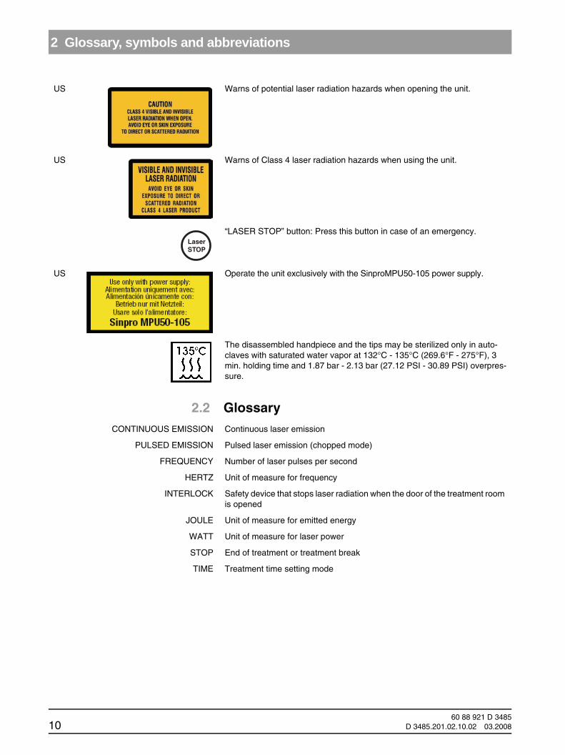
2.2 Glossary
US Warns of potential laser radiation hazards when opening the unit.
US Warns of Class 4 laser radiation hazards when using the unit.
“LASER STOP” button: Press this button in case of an emergency.
US Operate the unit exclusively with the SinproMPU50-105 power supply.
The disassembled handpiece and the tips may be sterilized only in auto-claves with saturated water vapor at 132°C - 135°C (269.6°F - 275°F), 3 min. holding time and 1.87 bar - 2.13 bar (27.12 PSI - 30.89 PSI) overpres-sure.
LaserSTOP
CONTINUOUS EMISSION Continuous laser emission
PULSED EMISSION Pulsed laser emission (chopped mode)
FREQUENCY Number of laser pulses per second
HERTZ Unit of measure for frequency
INTERLOCK Safety device that stops laser radiation when the door of the treatment room is opened
JOULE Unit of measure for emitted energy
WATT Unit of measure for laser power
STOP End of treatment or treatment break
TIME Treatment time setting mode
60 88 921 D 348510 D 3485.201.02.10.02 03.2008

2 Glossary, symbols and abbreviations
båÖäáëÜ
båÖäáëÜ
2.3 Abbreviationscm2 Square centimeter
Hz Hertz
s Seconds
W Watt
mW Milliwatt (one thousandth of a watt)
J Joule
nm Nanometer
V Volt
IR Infrared diode
NOHD NOHD (nominal ocular hazard distance) according to EN 60825-1: 1993 + A1: 1997 + A2: 2001
60 88 921 D 3485D 3485.201.02.10.02 03.2008 11

3 Introduction
3 Introduction
3.1 Classification
According to the applicable standards, the SIROLaser is classified as follows:
Class I Type B according to EN IEC 60601-1: 1990 + A1: 1993 + A2: 1 1995Class IIb (according to Council Directive 93/42/EEC)
Class IV laser device according to IEC 60825-1: 1993 + A1: 1997 + A2: 2001
Degree of protection according to EN IEC 60601-1: 1990 + A1: 1993 + A2: 1 1995 Medical device: IP 20 (cover not waterproof); Foot switch: IPX5
CAUTION The actual laser device cannot be sterilized. However, those accessory parts which come into direct contact must be sterilized.
WARNING The unit is not suitable for use in the presence of anesthetics that are flamma-ble when in contact with air, oxygen or nitrogen monoxide.
3.2 Safety precautions
SIROLaser was manufactured in compliance with the provisions of Council directive 93/42/EWG concerning medical devices (MDD).
Please always observe the following precautions:
WARNING When disconnecting the optical fiber from the laser, always cover the the con-nector with one of the special protection caps supplied.
CAUTION Any use of the controls or adjustment possibilities in a manner not specified here may lead to a dangerous exposure to radiation.
CAUTION Never place your finger or any objects in the exit ports. This could cause dam-age to the optical instrument.
CAUTION Switch the laser unit OFF immediately in case of an emergency. To do this, press the "LASER STOP" button on the control panel.
60 88 921 D 348512 D 3485.201.02.10.02 03.2008

3 Introduction
båÖäáëÜ
båÖäáëÜ
Figure 1: “LASER STOP” button
Observe all labels on the laser unit.
WARNING In order to prevent false or improper use, this laser device must not be used by unauthorized persons.
WARNING Never direct the laser beam or the aiming beam toward a person's eye or thy-roid gland. All persons present in the room (patient, dentist and assistant) must always wear the laser protective goggles delivered along with the laser unit.
WARNING Never use optical instruments such as microscopes, eye loupes or magnifiers together with the original protective goggles. Otherwise sufficient eye protec-tion cannot be ensured.
CAUTION Always cover the connector of the optical fiber with one of the special protec-tion caps supplied.
WARNING The unit is not suitable for use in the presence of anesthetics that are flamma-ble when in contact with air, oxygen or nitrogen monoxide.
WARNING Oxygen-saturated materials such as cotton wool can catch fire owing to the high temperature that the unit reaches during operation. Label removers and flammable solutions used for cleaning and disinfecting the laser device should be allowed to evaporate before using the device. Observe fire hazards caused by flammable gases.
WARNING Never direct the laser beam toward paper, plastics or objects with dark surfac-es. They could catch fire due to the high temperatures produced by the laser.
60 88 921 D 3485D 3485.201.02.10.02 03.2008 13
3 Introduction
WARNING The laser vapor contains tissue particles. Always wear a face mask, as a risk of infection otherwise exists.
Please also observe the following:
NOTICE iThe unit may only be operated in rooms that comply with the requirements of Council Directive 89/336/EEC. Any applicable national or local legal require-ments must be complied with.
CAUTION Avoid interference of the laser emission caused by optical sensors of devices operated in the vicinity of the SIROLASER.
3.3 Transport and storage
3.3.1 Transport and storage
The SIROLaser comes in a case that ensures proper and easy transport.
However, please observe the following:
CAUTION Do not leave the laser unit in a vehicle parked in the sun. The inside tempera-ture of the car could thus heat up to a point where individual components may be damaged.
To ensure its proper storage, the device must always be kept in the case sup-plied by Sirona Dental Systems.
Thus stored, the SIROLaser can withstand the following ambient conditions:Temperatures from -40 °C to +70 °C
Relative humidity from 10% to 90%
Atmospheric pressure from 800 hPa to 1060 hPa
In its original transport packaging, the SIROLaser can withstand the following ambient conditions:
Temperatures from -40°C to +70°C
Relative humidity from 10% to 95%Atmospheric pressure from 800 hPa to 1060 hPa
3.3.2 Operating conditionsThe SIROLaser may be operated under the following environmental conditions:
Temperatures from +10°C to +33°C
Relative humidity from 10% to 95%Atmospheric pressure from 800 hPa to 1060 hPa
CAUTION Following transport and storage, let the laser unit adapt to room temperature for about one hour prior to operation to reduce the risk of malfunctions caused by condensation.
60 88 921 D 348514 D 3485.201.02.10.02 03.2008
3 Introduction
båÖäáëÜ
båÖäáëÜ
3.4 PrecautionsFailure to use the settings specified in this manual or performance of function tests other than those described here may lead to a dangerous exposure to radiation.
Sirona Dental Systems GmbH cannot be held liable for any damage caused by improper use or noncompliance with the instructions and information spec-ified in this manual.
Therefore, observe the following:
CAUTION SIROLaser may only be operated by trained and qualified personnel.
CAUTION Laser equipment must be protected against unauthorized access when not in use. This can be achieved, for example, by switching the laser off following use so that the electronic access key must be entered before using it again.
Set up the SIROLaser unit properly and completely before putting it into oper-ation (see Chapter 4).
Make sure that the electrical system is equipped with the required devices for protection against direct and indirect contact (thermo magnetic switches, residual current circuit breakers) and has been set up by a qualified electrician in compliance with the applicable standards.
National directives regarding electrical installations must be observed.
Verify that the line voltage corresponds to the voltage indicated on the rating plate of the switching power supply or in the technical specifications.
WARNING Do not use the laser unit if a visual inspection shows that it has been dam-aged.
WARNING Do not use the laser unit in the presence of flammable materials or substances.
If you accidentally spill liquid on the unit, immediately stop treatment, discon-nect the power supply and contact your local dental depot or your service cen-ter for assistance.
CAUTION Never under any circumstances try to disassemble the laser unit. This is limit-ed exclusively to trained and authorized personnel.
Do not place the unit near heat sources.
Do not cover the convection openings for air cooling on the sides of the unit.
CAUTION Make sure that no dust or dirt can enter the optical fiber socket or the optical system. Otherwise the unit could be permanently damaged.
60 88 921 D 3485D 3485.201.02.10.02 03.2008 15
3 Introduction
CAUTION Always protect the optical fiber and its connection socket with the special pro-tection caps. Prevent dust, dirt and foreign particles from entering the optical fiber socket. Make sure that the optical system is clean before connecting the optical fiber.
WARNING Prior to each treatment, the handpieces must be sterilized and the optical fi-bers must be steam sterilized.
CAUTION Switch the laser off immediately if the optical fiber is broken. Otherwise the tips may become hot.
NOTICE iThe tips must be checked for sure seating prior to each use.
60 88 921 D 348516 D 3485.201.02.10.02 03.2008
4 Installation
båÖäáëÜ
båÖäáëÜ
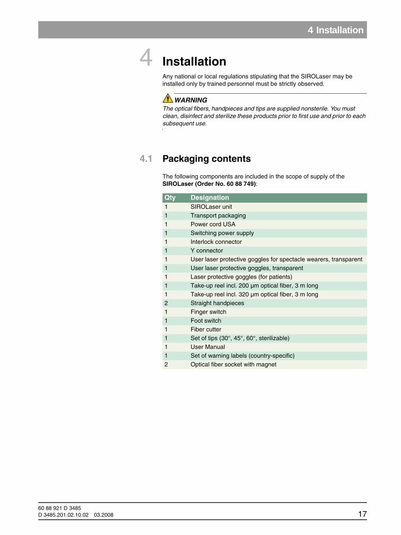
4 InstallationAny national or local regulations stipulating that the SIROLaser may be installed only by trained personnel must be strictly observed.
WARNING The optical fibers, handpieces and tips are supplied nonsterile. You must clean, disinfect and sterilize these products prior to first use and prior to each subsequent use.
4.1 Packaging contents
The following components are included in the scope of supply of the SIROLaser (Order No. 60 88 749):
Qty Designation1 SIROLaser unit
1 Transport packaging1 Power cord USA
1 Switching power supply
1 Interlock connector1 Y connector
1 User laser protective goggles for spectacle wearers, transparent
1 User laser protective goggles, transparent1 Laser protective goggles (for patients)
1 Take-up reel incl. 200 µm optical fiber, 3 m long
1 Take-up reel incl. 320 µm optical fiber, 3 m long2 Straight handpieces
1 Finger switch
1 Foot switch1 Fiber cutter
1 Set of tips (30°, 45°, 60°, sterilizable)
1 User Manual1 Set of warning labels (country-specific)
2 Optical fiber socket with magnet
60 88 921 D 3485D 3485.201.02.10.02 03.2008 17
4 Installation
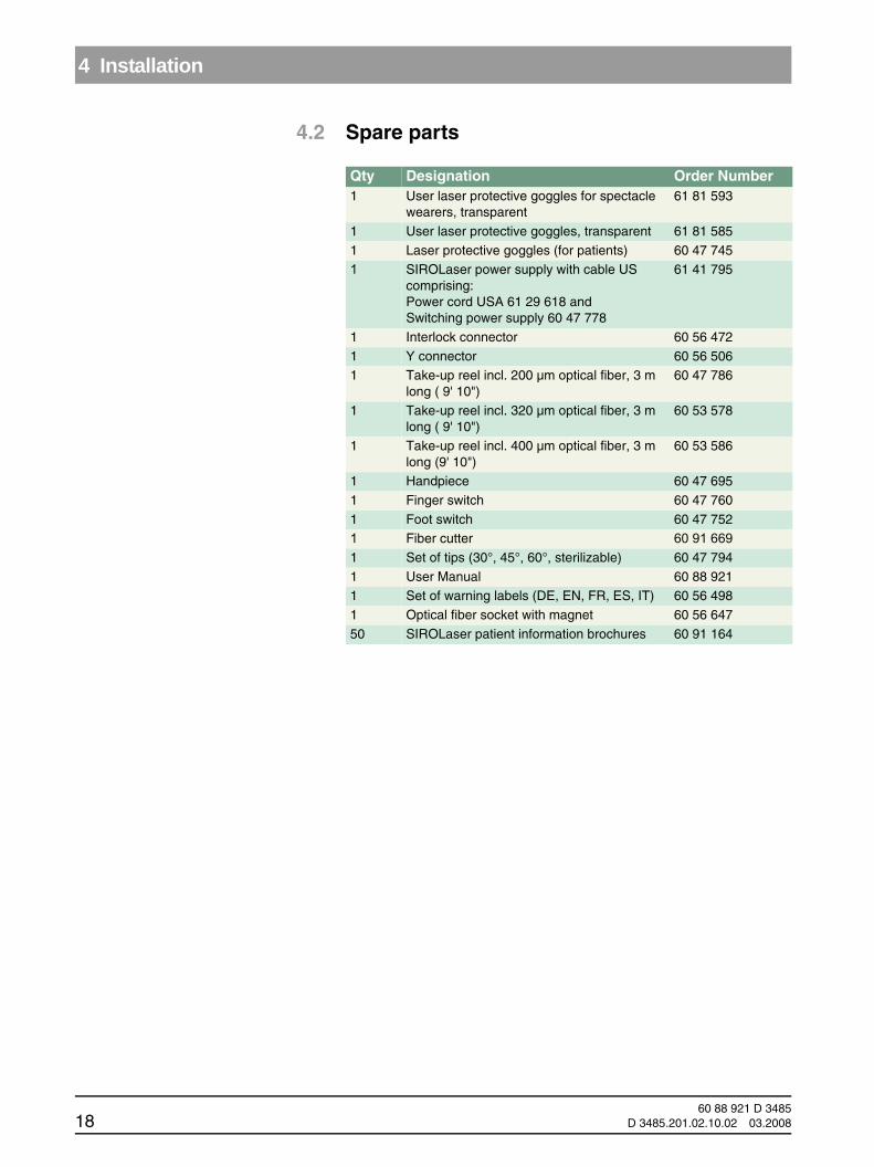
4.2 Spare parts
Qty Designation Order Number1 User laser protective goggles for spectacle
wearers, transparent61 81 593
1 User laser protective goggles, transparent 61 81 585
1 Laser protective goggles (for patients) 60 47 7451 SIROLaser power supply with cable US
comprising:Power cord USA 61 29 618 and Switching power supply 60 47 778
61 41 795
1 Interlock connector 60 56 472
1 Y connector 60 56 5061 Take-up reel incl. 200 µm optical fiber, 3 m
long ( 9' 10")60 47 786
1 Take-up reel incl. 320 µm optical fiber, 3 m long ( 9' 10")
60 53 578
1 Take-up reel incl. 400 µm optical fiber, 3 m long (9' 10")
60 53 586
1 Handpiece 60 47 695
1 Finger switch 60 47 760
1 Foot switch 60 47 7521 Fiber cutter 60 91 6691 Set of tips (30°, 45°, 60°, sterilizable) 60 47 794
1 User Manual 60 88 9211 Set of warning labels (DE, EN, FR, ES, IT) 60 56 498
1 Optical fiber socket with magnet 60 56 647
50 SIROLaser patient information brochures 60 91 164
60 88 921 D 348518 D 3485.201.02.10.02 03.2008
4 Installation
båÖäáëÜ
båÖäáëÜ
4.3 Interlock
4.3.1 ExplanationThe interlock is a safety device that stops laser radiation whenever the door of the treatment room is opened. The interlock circuit must be connected to a switch that is located near the door of the treatment room in order to ensure automatic interruption of the laser emission.
NOTICE iThe installation must be performed by a qualified electrician who is also re-sponsible for the installation and maintenance of the electrical system to which the SIROLaser is connected.
Please request our technical data sheet with circuit diagram for the installa-tion of the interlock circuit (Safety Check Service Manual, REF 6196542).
NOTICE iAdditional or different safety precautions required by the applicable national or local regulations for the protection of dentists, assistant personnel, or patients must also be observed.
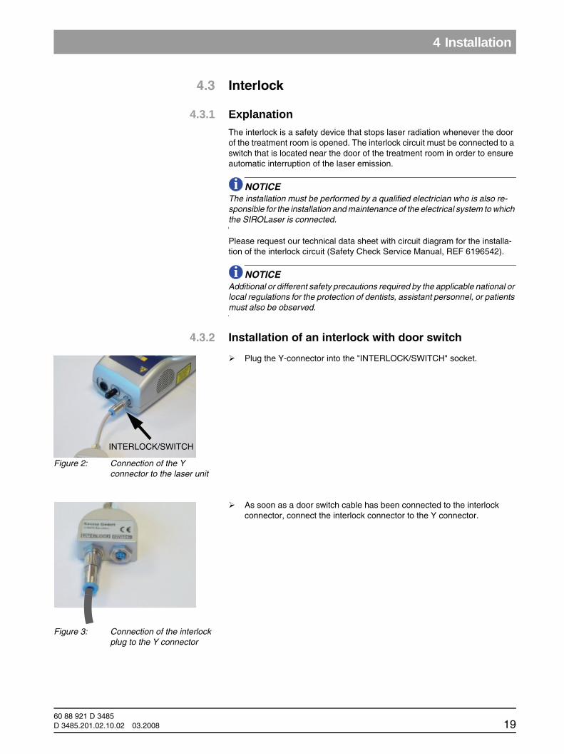
4.3.2 Installation of an interlock with door switch
Plug the Y-connector into the "INTERLOCK/SWITCH" socket.
As soon as a door switch cable has been connected to the interlock connector, connect the interlock connector to the Y connector.
Figure 2: Connection of the Y connector to the laser unit
INTERLOCK/SWITCH
Figure 3: Connection of the interlock plug to the Y connector
60 88 921 D 3485D 3485.201.02.10.02 03.2008 19

4 Installation
4.4 Connection of the foot switch to the door switch (interlock)
Plug the foot switch cable into the socket of the Y connector.
NOTICE iThe foot switch has an IPX5 degree of protection. Therefore this foot switch must not be used in hospital operating rooms. If you would like to operate the laser unit with the foot switch in a hospital or operating room, please contact Sirona Dental Systems LLC or your local dental depot.
4.5 Installation of a foot or finger switch without a door switch (interlock)
The treatment room must be protected by suitable measures (in compliance with IEC 60825-1), e.g. by closing the doors.
Figure 4: Connection of the foot switch
60 88 921 D 348520 D 3485.201.02.10.02 03.2008
4 Installation
båÖäáëÜ
båÖäáëÜ
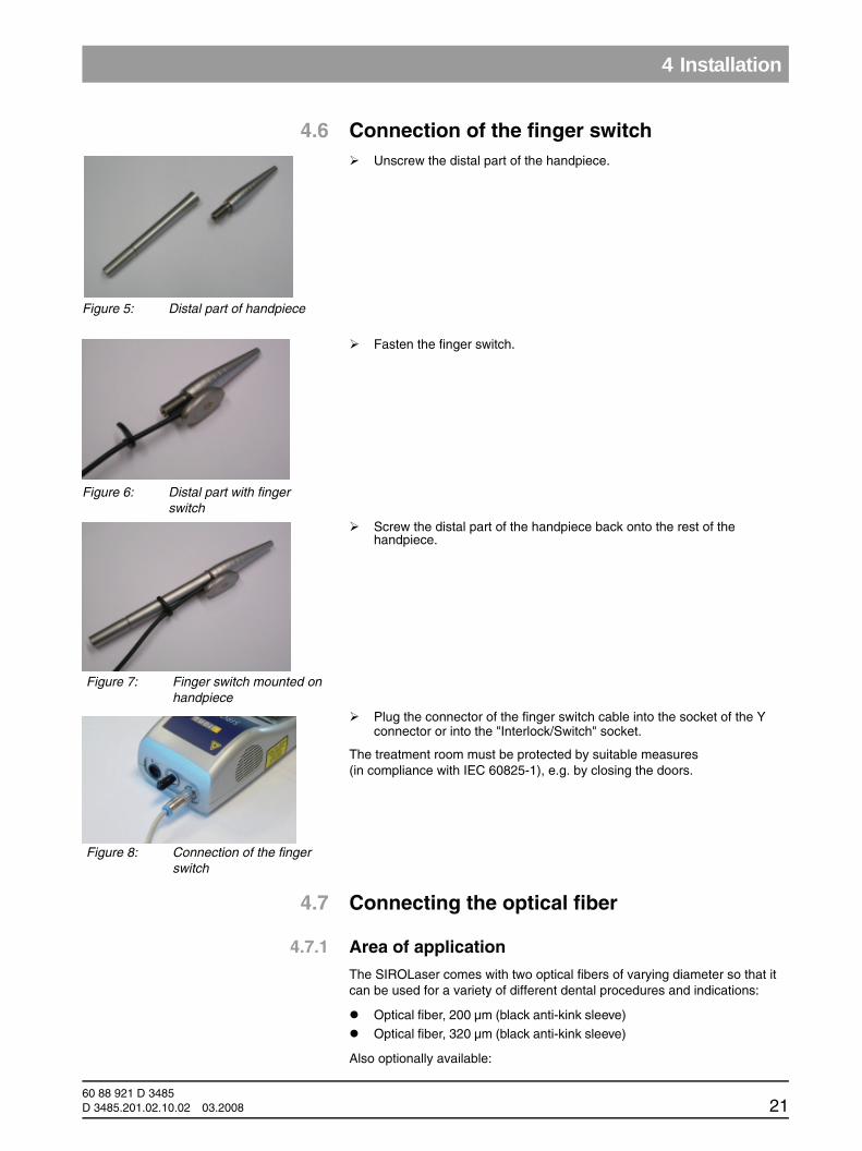
4.6 Connection of the finger switchUnscrew the distal part of the handpiece.
Fasten the finger switch.
Screw the distal part of the handpiece back onto the rest of the handpiece.
Plug the connector of the finger switch cable into the socket of the Y connector or into the "Interlock/Switch" socket.
The treatment room must be protected by suitable measures (in compliance with IEC 60825-1), e.g. by closing the doors.
4.7 Connecting the optical fiber
4.7.1 Area of application
The SIROLaser comes with two optical fibers of varying diameter so that it can be used for a variety of different dental procedures and indications:
Optical fiber, 200 µm (black anti-kink sleeve)
Optical fiber, 320 µm (black anti-kink sleeve)
Also optionally available:
Figure 5: Distal part of handpiece
Figure 6: Distal part with finger switch
Figure 7: Finger switch mounted on handpiece
Figure 8: Connection of the finger switch
60 88 921 D 3485D 3485.201.02.10.02 03.2008 21
4 Installation
Optical fiber, 400 µm (blue anti-kink sleeve)
The laser software will prompt you to select the correct optical fiber for each indication.
SIROLaser optical fibers have a standard SMA-905 connection and can be used only with the SIROLaser in the spectral range of 970 nm ± 15 nm.
If optical fibers from other manufacturers are used, physical properties such as load carrying capacity and transmission behavior may vary. Sirona Dental Systems GmbH therefore assumes no liability in such cases.
Therefore, always use only Sirona optical fibers.
4.7.2 Initial use of an optical fiber
Initial check
Before using an optical fiber for the first time, check its best-before date. A nonsterile optical fiber can be used maximally 4 years after its month of manufacture. This information is printed on the product label of the packaging.
WARNING If the optical fiber is used after the best-before date, some of its physical properties, e.g. its load carrying strength and transmission behavior, will change, thus posing a hazard to the health of the patient, the dentist and the dental assistant.
Do not use the laser probe if its packaging is damaged or the best-before month has been exceeded.
After removing the optical fibers from their original packaging, perform a visual check to make sure that they were not damaged during shipment.
Initial startup
CAUTION The optical fiber and take-up reel must be sterilized prior to initial use.
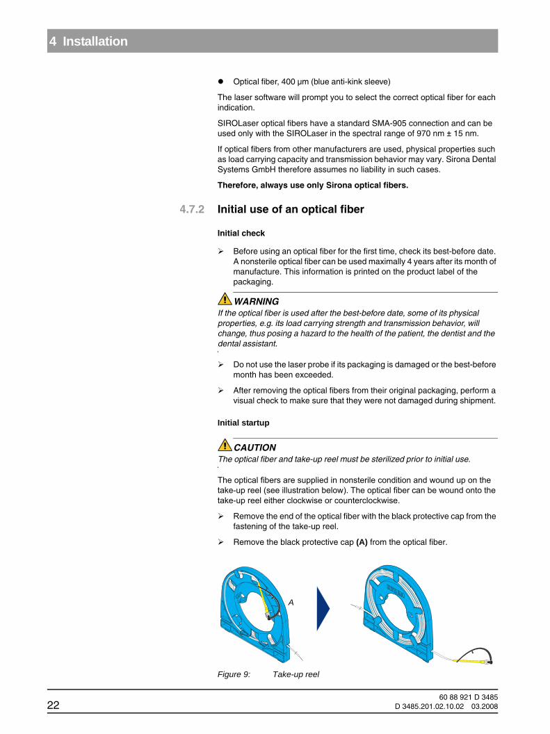
The optical fibers are supplied in nonsterile condition and wound up on the take-up reel (see illustration below). The optical fiber can be wound onto the take-up reel either clockwise or counterclockwise.
Remove the end of the optical fiber with the black protective cap from the fastening of the take-up reel.
Remove the black protective cap (A) from the optical fiber.
Figure 9: Take-up reel
A
60 88 921 D 348522 D 3485.201.02.10.02 03.2008
4 Installation
båÖäáëÜ
båÖäáëÜ
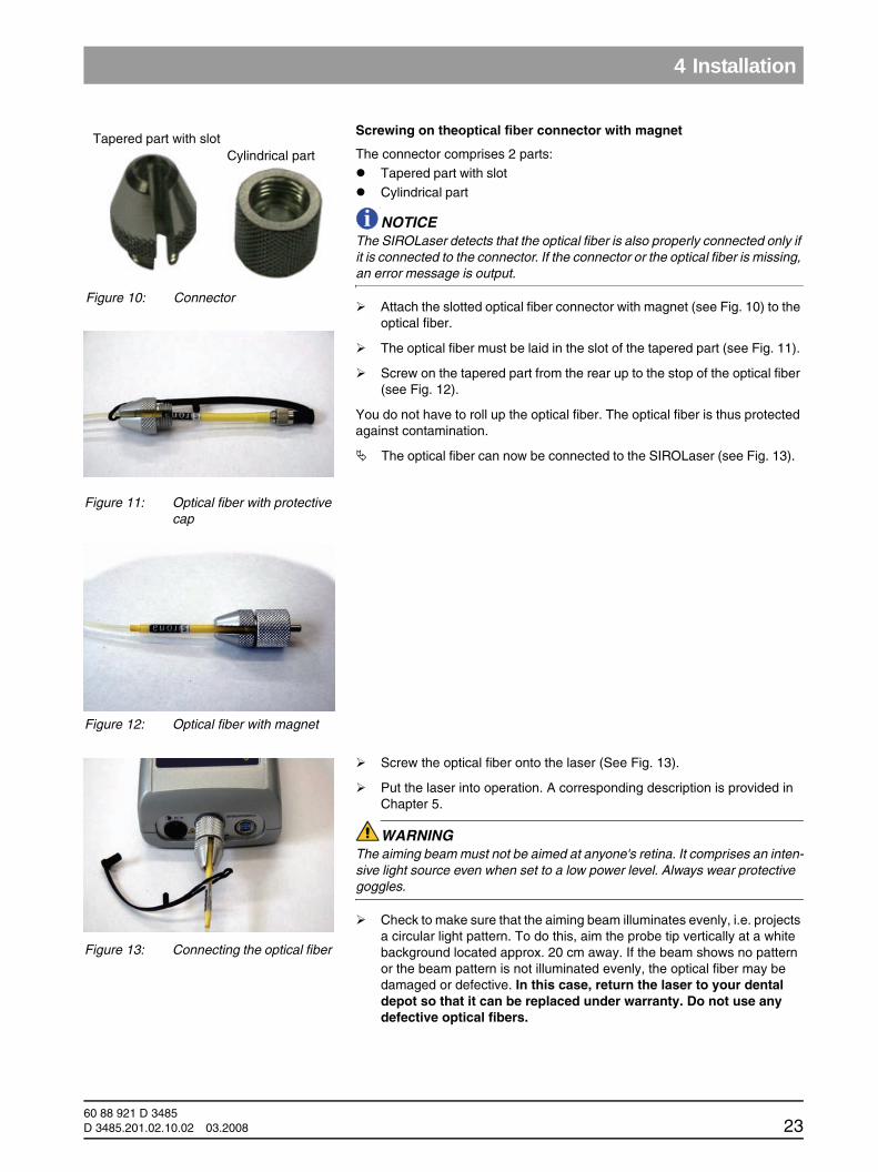
Screwing on theoptical fiber connector with magnet
The connector comprises 2 parts: Tapered part with slot
Cylindrical part
NOTICE iThe SIROLaser detects that the optical fiber is also properly connected only if it is connected to the connector. If the connector or the optical fiber is missing, an error message is output.
Attach the slotted optical fiber connector with magnet (see Fig. 10) to the optical fiber.
The optical fiber must be laid in the slot of the tapered part (see Fig. 11).
Screw on the tapered part from the rear up to the stop of the optical fiber (see Fig. 12).
You do not have to roll up the optical fiber. The optical fiber is thus protected against contamination.
The optical fiber can now be connected to the SIROLaser (see Fig. 13).
Screw the optical fiber onto the laser (See Fig. 13).
Put the laser into operation. A corresponding description is provided in Chapter 5.
WARNING The aiming beam must not be aimed at anyone's retina. It comprises an inten-sive light source even when set to a low power level. Always wear protective goggles.
Check to make sure that the aiming beam illuminates evenly, i.e. projects a circular light pattern. To do this, aim the probe tip vertically at a white background located approx. 20 cm away. If the beam shows no pattern or the beam pattern is not illuminated evenly, the optical fiber may be damaged or defective. In this case, return the laser to your dental depot so that it can be replaced under warranty. Do not use any defective optical fibers.
Figure 10: Connector
Cylindrical partTapered part with slot
Figure 11: Optical fiber with protective cap
Figure 12: Optical fiber with magnet
Figure 13: Connecting the optical fiber
60 88 921 D 3485D 3485.201.02.10.02 03.2008 23
4 Installation
Preparation
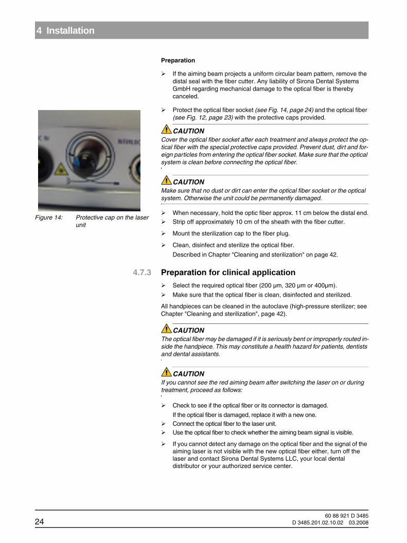
If the aiming beam projects a uniform circular beam pattern, remove the distal seal with the fiber cutter. Any liability of Sirona Dental Systems GmbH regarding mechanical damage to the optical fiber is thereby canceled.
Protect the optical fiber socket (see Fig. 14, page 24) and the optical fiber (see Fig. 12, page 23) with the protective caps provided.
CAUTION Cover the optical fiber socket after each treatment and always protect the op-tical fiber with the special protective caps provided. Prevent dust, dirt and for-eign particles from entering the optical fiber socket. Make sure that the optical system is clean before connecting the optical fiber.
CAUTION Make sure that no dust or dirt can enter the optical fiber socket or the optical system. Otherwise the unit could be permanently damaged.
When necessary, hold the optic fiber approx. 11 cm below the distal end.
Strip off approximately 10 cm of the sheath with the fiber cutter.
Mount the sterilization cap to the fiber plug.
Clean, disinfect and sterilize the optical fiber.
Described in Chapter "Cleaning and sterilization" on page 42.
4.7.3 Preparation for clinical applicationSelect the required optical fiber (200 µm, 320 µm or 400µm).
Make sure that the optical fiber is clean, disinfected and sterilized.
All handpieces can be cleaned in the autoclave (high-pressure sterilizer; see Chapter "Cleaning and sterilization", page 42).
CAUTION The optical fiber may be damaged if it is seriously bent or improperly routed in-side the handpiece. This may constitute a health hazard for patients, dentists and dental assistants.
CAUTION If you cannot see the red aiming beam after switching the laser on or during treatment, proceed as follows:
Check to see if the optical fiber or its connector is damaged.
If the optical fiber is damaged, replace it with a new one.Connect the optical fiber to the laser unit.Use the optical fiber to check whether the aiming beam signal is visible.
If you cannot detect any damage on the optical fiber and the signal of the aiming laser is not visible with the new optical fiber either, turn off the laser and contact Sirona Dental Systems LLC, your local dental distributor or your authorized service center.
Figure 14: Protective cap on the laser unit
60 88 921 D 348524 D 3485.201.02.10.02 03.2008

4 Installation
båÖäáëÜ
båÖäáëÜ
WARNING Use of the laser unit when the aiming beam is not functioning properly may cause injuries to operating personnel, assistants or patients.
CAUTION The optical fiber must be cleaned and disinfected prior to the first treatment.
CAUTION Remove the protective caps only for operation.
CAUTION Never touch the connector ends and protect them against damage.
CAUTION Never bend, fold or jam the optical fiber, as this might cause it to break.
CAUTION Never pull at the optical fiber.
CAUTION Note the maximum permissible bending radius of the optical fiber!• Short-term (during use): 100 x radius of optical fiber• Long-term (during storage): 600 x radius of optical fiber
NOTICE iThe unit detects whether the optical fiber is connected via the magnet.
Inserting the optical fiber into a sterilized handpiece
Loosen the proximal end of the handpiece.
Insert the optical fiber in the handpiece.
Figure 15: Inserting the optical fiber into the handpiece
60 88 921 D 3485D 3485.201.02.10.02 03.2008 25
4 Installation
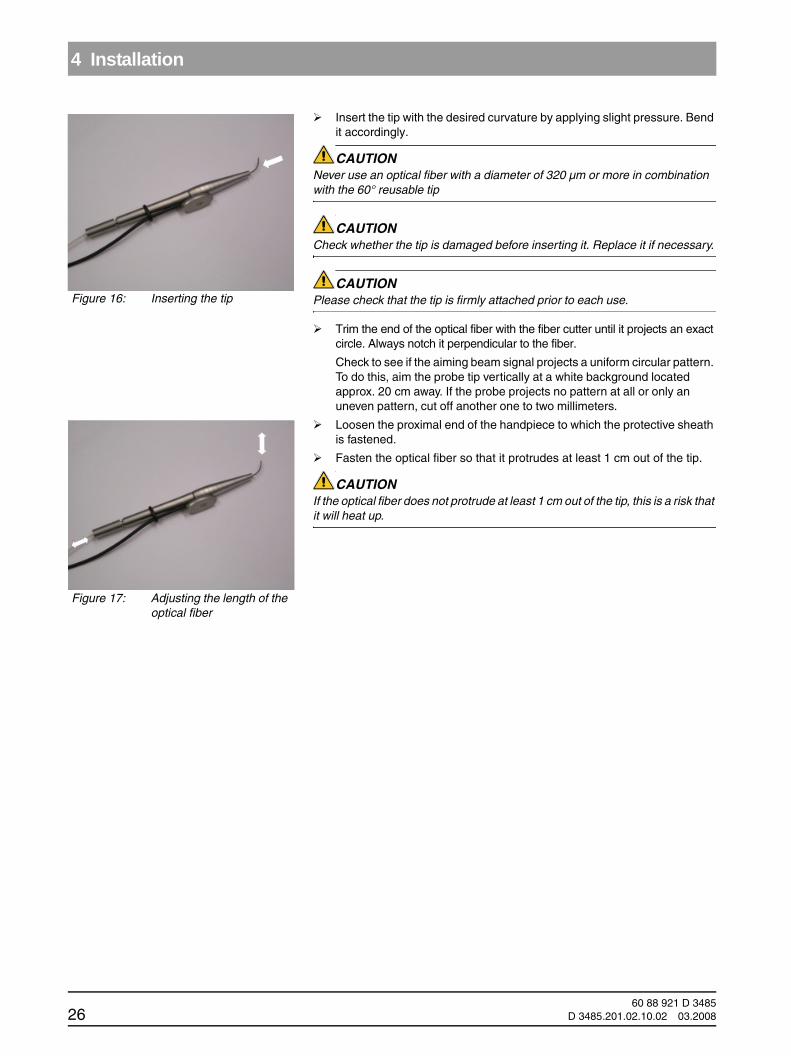
Insert the tip with the desired curvature by applying slight pressure. Bend it accordingly.
CAUTION Never use an optical fiber with a diameter of 320 µm or more in combination with the 60° reusable tip
CAUTION Check whether the tip is damaged before inserting it. Replace it if necessary.
CAUTION Please check that the tip is firmly attached prior to each use.
Trim the end of the optical fiber with the fiber cutter until it projects an exact circle. Always notch it perpendicular to the fiber.
Check to see if the aiming beam signal projects a uniform circular pattern. To do this, aim the probe tip vertically at a white background located approx. 20 cm away. If the probe projects no pattern at all or only an uneven pattern, cut off another one to two millimeters.
Loosen the proximal end of the handpiece to which the protective sheath is fastened.Fasten the optical fiber so that it protrudes at least 1 cm out of the tip.
CAUTION If the optical fiber does not protrude at least 1 cm out of the tip, this is a risk that it will heat up.
Figure 16: Inserting the tip
Figure 17: Adjusting the length of the optical fiber
60 88 921 D 348526 D 3485.201.02.10.02 03.2008
4 Installation
båÖäáëÜ
båÖäáëÜ
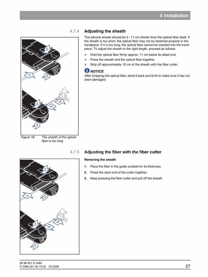
4.7.4 Adjusting the sheathThe silicone sheath should be 5 - 11 cm shorter than the optical fiber itself. If the sheath is too short, the optical fiber may not be fastened properly in the handpiece. If it is too long, the optical fiber cannot be inserted into the hand-piece. To adjust the sheath to the right length, proceed as follows:
Hold the optical fiber firmly approx. 11 cm below its distal end.
Press the sheath and the optical fiber together.
Strip off approximately 10 cm of the sheath with the fiber cutter.
NOTICE iAfter Stripping the optical fiber, bend it back and forth to make sure it has not been damaged.
4.7.5 Adjusting the fiber with the fiber cutter
Removing the sheath
1. Place the fiber in the guide suitable for its thickness.
2. Press the open end of the cutter together.
3. Keep pressing the fiber cutter and pull off the sheath.
Figure 18: The sheath of the optical fiber is too long
2.
135 C°
2.
1.
2.
135 C°
3.
3.2.
2.
135 C°
2.
1.
2.
135 C°
3.
3.2.
60 88 921 D 3485D 3485.201.02.10.02 03.2008 27
4 Installation
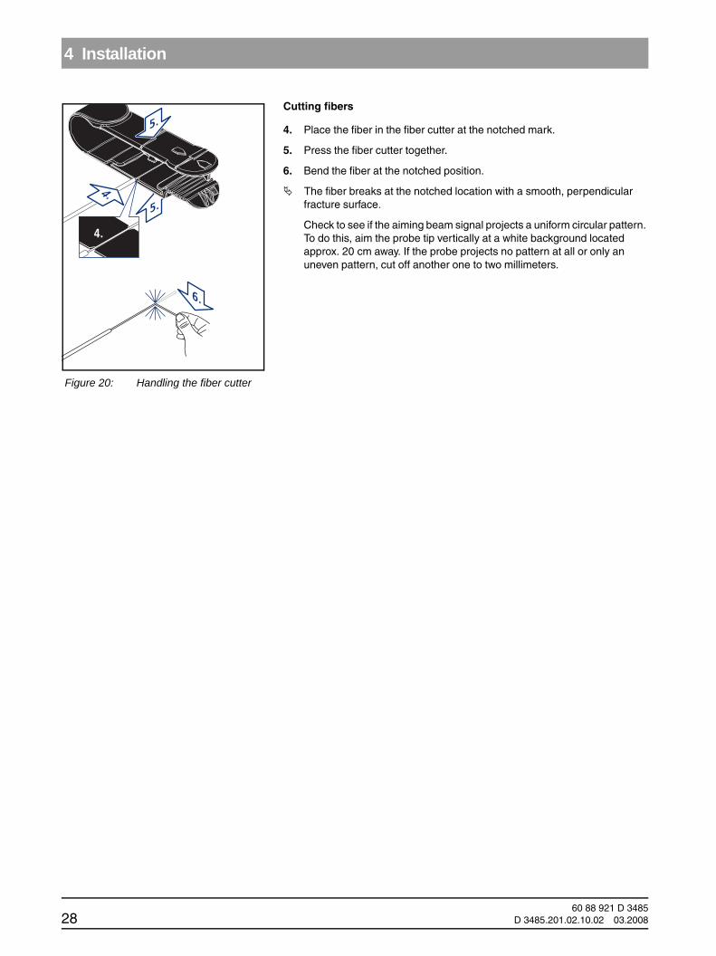
Cutting fibers
4. Place the fiber in the fiber cutter at the notched mark.
5. Press the fiber cutter together.
6. Bend the fiber at the notched position.
The fiber breaks at the notched location with a smooth, perpendicular fracture surface.
Check to see if the aiming beam signal projects a uniform circular pattern. To do this, aim the probe tip vertically at a white background located approx. 20 cm away. If the probe projects no pattern at all or only an uneven pattern, cut off another one to two millimeters.
6.
5.
135 C°
4.
4.
5.
Figure 20: Handling the fiber cutter
60 88 921 D 348528 D 3485.201.02.10.02 03.2008
4 Installation
båÖäáëÜ
båÖäáëÜ
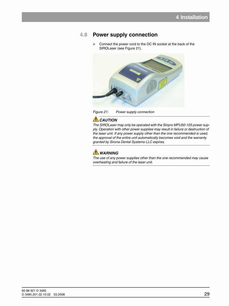
4.8 Power supply connection
Connect the power cord to the DC IN socket at the back of the SIROLaser (see Figure 21).
Figure 21: Power supply connection
CAUTION The SIROLaser may only be operated with the Sinpro MPU50-105 power sup-ply. Operation with other power supplies may result in failure or destruction of the laser unit. If any power supply other than the one recommended is used, the approval of the entire unit automatically becomes void and the warranty granted by Sirona Dental Systems LLC expires.
WARNING The use of any power supplies other than the one recommended may cause overheating and failure of the laser unit.
60 88 921 D 3485D 3485.201.02.10.02 03.2008 29
5 Operating Instructions
5 Operating InstructionsCAUTION
Protect the optical fiber and its connector by attaching the protective caps pro-vided after each treatment (see Fig. 14, page 24).
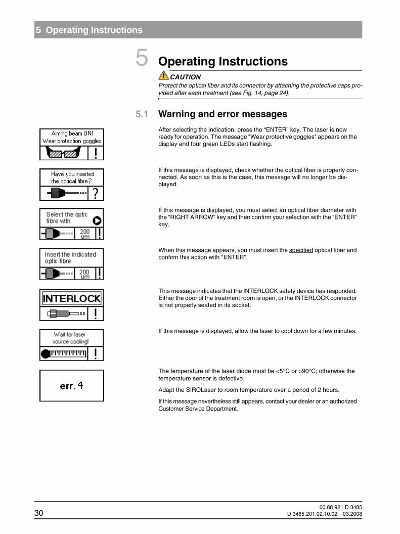
5.1 Warning and error messages
After selecting the indication, press the “ENTER” key. The laser is now ready for operation. The message "Wear protective goggles" appears on the display and four green LEDs start flashing.
If this message is displayed, check whether the optical fiber is properly con-nected. As soon as this is the case, this message will no longer be dis-played.
If this message is displayed, you must select an optical fiber diameter with the “RIGHT ARROW” key and then confirm your selection with the “ENTER” key.
When this message appears, you must insert the specified optical fiber and confirm this action with "ENTER".
This message indicates that the INTERLOCK safety device has responded. Either the door of the treatment room is open, or the INTERLOCK connector is not properly seated in its socket.
If this message is displayed, allow the laser to cool down for a few minutes.
The temperature of the laser diode must be <5°C or >90°C; otherwise the temperature sensor is defective.
Adapt the SIROLaser to room temperature over a period of 2 hours.
If this message nevertheless still appears, contact your dealer or an authorized Customer Service Department.
60 88 921 D 348530 D 3485.201.02.10.02 03.2008
5 Operating Instructions
båÖäáëÜ
båÖäáëÜ
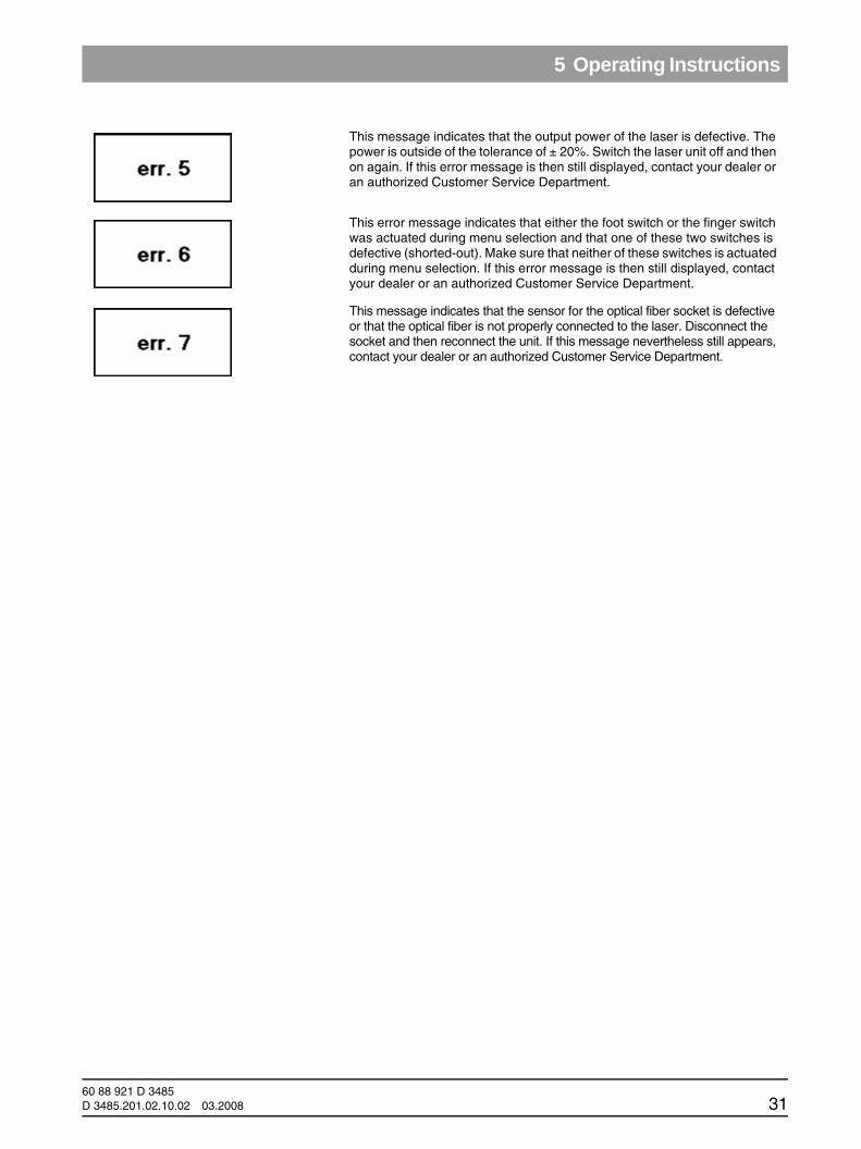
This message indicates that the output power of the laser is defective. The power is outside of the tolerance of ± 20%. Switch the laser unit off and then on again. If this error message is then still displayed, contact your dealer or an authorized Customer Service Department.
This error message indicates that either the foot switch or the finger switch was actuated during menu selection and that one of these two switches is defective (shorted-out). Make sure that neither of these switches is actuated during menu selection. If this error message is then still displayed, contact your dealer or an authorized Customer Service Department.
This message indicates that the sensor for the optical fiber socket is defective or that the optical fiber is not properly connected to the laser. Disconnect the socket and then reconnect the unit. If this message nevertheless still appears, contact your dealer or an authorized Customer Service Department.
60 88 921 D 3485D 3485.201.02.10.02 03.2008 31

5 Operating Instructions
5.2 Switching the laser unit on and off
Once you have completed the installation procedure, press the “ENTER” key to switch on the laser unit.
If the SIROLaser is not operated for more than two minutes, it automatically switches to the standby mode The unit can remain connected in the standby mode.
5.3 Control panel
Figure 22: Control panel
5.4 Electronic access key
The SIROLaser may be operated only by authorized personnel. When the unit has powered up and its self-test has been completed, you will be prompted to enter an access code. This code is your electronic key. The access code comprises four numbers.
The code is: 6 2 5 1To enter the access code, press the following keys consecutively:
Use the "RIGHT ARROW" key to scroll through to one of the numbers.
Change from one selected number to the next one in the series by pressing the "ENTER" key.
WARNING Do not give the access code to unauthorized third parties. This would create a risk of the laser being misused by unauthorized persons.
To switch the laser unit off, select "OFF AREA". Then press "ENTER" and disconnect the power cord.
“LEFT ARROW” key Navigate to the left. Parameters decrease. Quit certain menus.
“ENTER” key Confirms, starts or stops a selected action following setup.
“RIGHT ARROW” key Navigate to the right (in all menus). Parameters increase.
“LASER STOP” button You can stop the laser in an emergency with the "LASER STOP" button.
60 88 921 D 348532 D 3485.201.02.10.02 03.2008

5 Operating Instructions
båÖäáëÜ
båÖäáëÜ
5.5 Setting the interface language
Press the "RIGHT ARROW" key to select the treatment area.
Press the “LEFT ARROW” key twice. The following screen appears on the display:
Press "ENTER".
A new screen appears on the display.
Press the “ENTER” key until the menu item “LANGUAGE EN” is highlighted.
Press the “RIGHT ARROW” key until the desired language appears.
The following abbreviations are used:
Press "ENTER".
Press the “LEFT ARROW” key.
You are now in the main menu.
5.6 Main menu
The following section describes the main menu. Two different menu items are introduced there, and you also will find out how to access the submenus.
EN English
FR French
IT Italian
ESP Spanish
DE German
60 88 921 D 3485D 3485.201.02.10.02 03.2008 33

5 Operating Instructions
Press the “RIGHT ARROW” key to select the treatment area.
SURGERY AREAPress the “ENTER” key to access the surgery area. In this area you will find a number of surgical submenus with preset treatment parameters.
PERIODONTICS AREAPress the “ENTER” key to access the periodontology area.
In this area you will find a number of submenus for periodontology with preset treatment parameters.
Press the “ENTER” key to access the endodontics area.
In this area you will find a number of submenus for endodontics with preset treatment parameters.
Press the “ENTER” key to access the MANUAL SETTING AREA.
In this area you can manually configure up to 10 different sets of treatment parameters. The sets are stored and will be available for use in future treatment sessions.
Press the “ENTER” key to access the setup area.
In this submenu you can make basic settings such as interface language, sound and brightness. The service menu is also located in this area.
Press the “ENTER” key to switch off the laser.
60 88 921 D 348534 D 3485.201.02.10.02 03.2008
5 Operating Instructions
båÖäáëÜ
båÖäáëÜ
5.7 SURGERY"", "PERIODONTICS" and "ENDODONTICS" submenus.
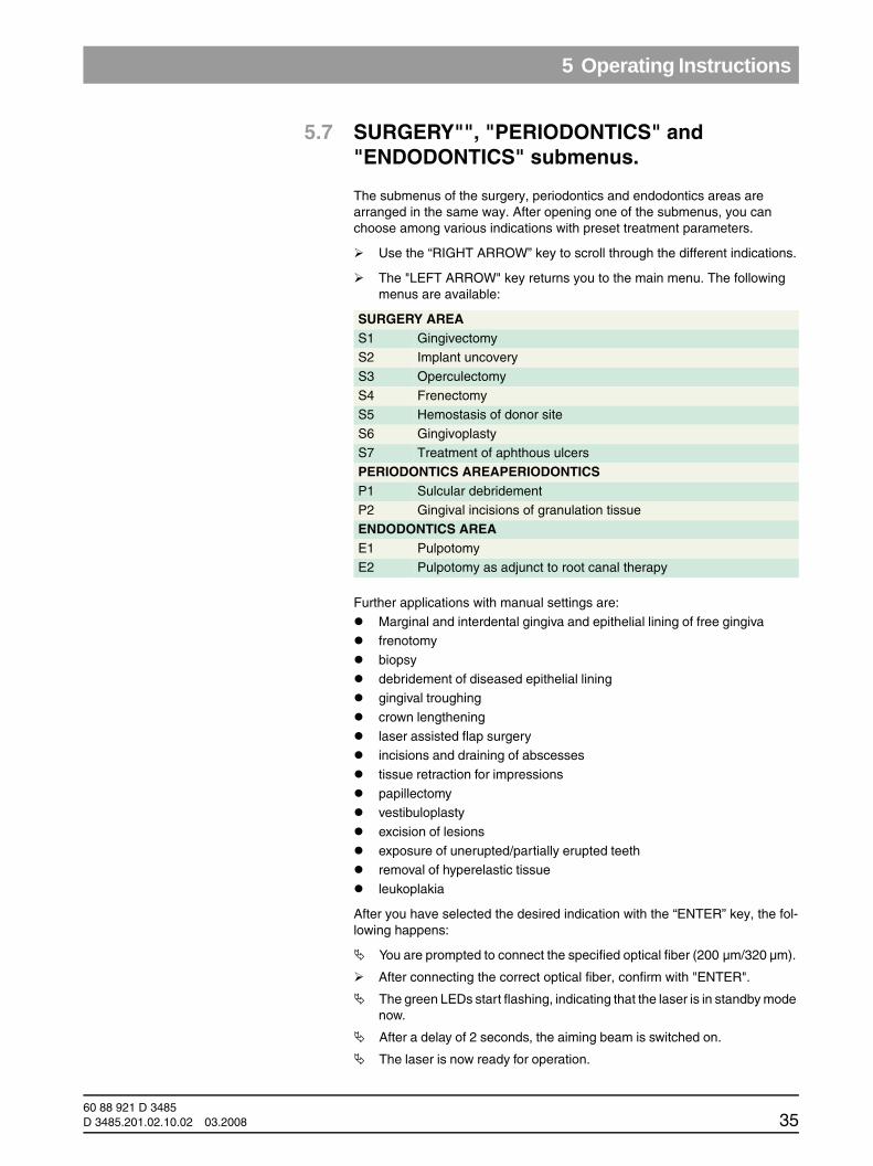
The submenus of the surgery, periodontics and endodontics areas are arranged in the same way. After opening one of the submenus, you can choose among various indications with preset treatment parameters.
Use the “RIGHT ARROW” key to scroll through the different indications.
The "LEFT ARROW" key returns you to the main menu. The following menus are available:
Further applications with manual settings are:
Marginal and interdental gingiva and epithelial lining of free gingivafrenotomy
biopsy
debridement of diseased epithelial lininggingival troughing
crown lengthening
laser assisted flap surgeryincisions and draining of abscesses
tissue retraction for impressions
papillectomyvestibuloplasty
excision of lesions
exposure of unerupted/partially erupted teethremoval of hyperelastic tissue
leukoplakia
After you have selected the desired indication with the “ENTER” key, the fol-lowing happens:
You are prompted to connect the specified optical fiber (200 µm/320 µm).
After connecting the correct optical fiber, confirm with "ENTER".
The green LEDs start flashing, indicating that the laser is in standby mode now.
After a delay of 2 seconds, the aiming beam is switched on.
The laser is now ready for operation.
SURGERY AREAS1 GingivectomyS2 Implant uncovery
S3 Operculectomy
S4 FrenectomyS5 Hemostasis of donor site
S6 Gingivoplasty
S7 Treatment of aphthous ulcersPERIODONTICS AREAPERIODONTICSP1 Sulcular debridement
P2 Gingival incisions of granulation tissueENDODONTICS AREAE1 Pulpotomy
E2 Pulpotomy as adjunct to root canal therapy
60 88 921 D 3485D 3485.201.02.10.02 03.2008 35

5 Operating Instructions
Wear protective goggles whenever the aiming beam is switched on.
WARNING All persons present in the room (operator, assistant and patient) must wear the supplied laser protective goggles whenever the green LEDs are activated.
WARNING Any actuation of the foot or finger switch activates the laser unit.
The following is a typical example of a treatment submenu.
Figure 23: Example of a treatment submenu
1. Selected program: in our example P3: a nonexistent virtual setting.
2. Pulse duration in milliseconds: in single pulse or auto-repeat mode. If set to any time, laser radiation will stop after this time, even if you continue to press the foot control or finger switch. If set to zero, “------” appears on the display, and the laser remains activated as long you press the foot control or finger switch. In the auto repeat mode, the laser unit switches back on after two sec. if the foot switch or finger switch is actuated.
NOTICE iIn the preset menus, the laser activation time cannot be modified by the user.
3. Laser radiation: ON when the foot control or finger switch is actuated,OFF when the laser is in standby mode.
4. Selected laser power: in our example, 0.8 W peak power. Using the “RIGHT ARROW” and “LEFT ARROW” keys, you can adjust the emitted power between 0.5 W and 7 W in increments of 0.1 W.
WARNING The preset power levels are considered to be safe for patients. Setting a higher power level entails the risk of overheating the patient’s soft or hard tissue. Set-ting the power to excessively low levels may result in reduced treatment effica-cy.
5. Frequency: Modulation frequency of the laser unit. The frequency range extends from 1 to 10,000 Hz. If set to zero, CW (for continuous wave mode) is displayed.
60 88 921 D 348536 D 3485.201.02.10.02 03.2008

5 Operating Instructions
båÖäáëÜ
båÖäáëÜ
NOTICE iIn the preset menus, the frequency cannot be modified by the user.
6. Treatment energy: The system calculates the energy used during treatment (in mJ) from the power values and the selected laser activation time. If no activation time has been preset, the energy will not be calculated.
When you actuate the foot control or finger switch, the message “LASER ON” appears. At the same time, four yellow LEDs light up, the audible alarm sounds and the laser starts emitting. When you release the foot control or fin-ger switch to interrupt treatment, the laser is deactivated, but remains ready for operation.
Laser irradiation (and thus the treatment) can be terminated immediately by pressing the red “LASER STOP” emergency button.
To quit the selected preset menu, press the “ENTER” key.
A message stating that therapy has been terminated appears on the display.
"LEFT ARROW" key returns you to the main menu.
5.8 "MANUAL SETTING AREA" submenuAfter the "MANUAL SETTING AREA" is activated, a figure with configuration settings appears on the display (see Fig. 24).
Here you can select from ten different programs with the arrow keys.
Pressing the "ENTER" key takes you to the selected program (PP1 for program 1, PP2 for program 2 etc.......)
Confirm the optical fiber you would like to use for your personal settings (200µm or 320 µm) with "ENTER“, or change this selection with the "RIGHT ARROW" key.
The following happens after you select the submenu:
The green LEDs start flashing, indicating that the laser is in standby mode now.
The laser is now ready for operation.
Wear protective goggles whenever the aiming beam is switched on.
60 88 921 D 3485D 3485.201.02.10.02 03.2008 37

5 Operating Instructions
Figure 24: "MANUAL SETTING AREA" submenu
1. Selected program: in our example P3: a nonexistent virtual setting.
2. Laser activation time in milliseconds: in single pulse or auto-repeat mode. In the auto repeat mode, the laser unit switches back on after two seconds if the foot switch is actuated. If set to any time, laser radiation will stop after this time, even if you continue to press the foot control or finger switch. If set to zero, “------” appears on the display, and the laser remains activated as long you press the foot control or finger switch. You can set a time between 100 ms and 60 s (60,000 ms) in 50 ms intervals. When you press the key for more than 3 seconds, the value increases at a faster rate.
3. Laser radiation: ON when the foot control or finger switch is actuated,OFF when the laser is in standby mode.
4. Selected laser power: in our example, 0.8 W peak power. Using the “RIGHT ARROW” and “LEFT ARROW” keys, you can adjust the emitted power between 0.5 W and 7 W in increments of 0.1 W.
WARNING Setting excessively high power levels entails the risk of overheating the pa-tient’s soft or hard tissue. Setting the power to excessively low levels may re-sult in reduced treatment efficacy.
5. Frequency: Modulation frequency of the laser. The frequency range extends from 1 to 10,000 Hz. If set to zero, CW (for continuous wave mode) is displayed. Up to 100 Hz, the parameter value can be increased in 1 Hz increments Between 100 Hz and 1,000 Hz, the parameter value can be increased in 100 Hz increments. Between 1,000 Hz and 10,000 Hz, the parameter value can be increased in 1,000 Hz increments. When you press the "RIGHT ARROW" key for more than 3seconds, the value increases at a faster rate.
6. Treatment energy: The laser unit calculates the energy used during treatment (in mJ) from the power values and the selected laser activation time. If no activation time has been preset, the energy will not be calculated.
WARNING Following program selection, the SIROLaser is in the standby mode. Any ac-tuation of the foot control or finger switch activates the laser.
60 88 921 D 348538 D 3485.201.02.10.02 03.2008
5 Operating Instructions
båÖäáëÜ
båÖäáëÜ
When you actuate the foot control or finger switch, the message “LASER ON” appears. At the same time, four yellow LEDs light up, the audible alarm sounds and the laser starts emitting. When you release the foot control or fin-ger switch to interrupt treatment, the laser is deactivated, but remains ready for operation.
To change the power, press the "ENTER" key. As soon as the area has been selected, you can change the values by pressing the "RIGHT ARROW" and "LEFT ARROW" keys.
Laser irradiation (and thus the treatment) can be terminated immediately by pressing the red “LASER STOP” emergency button.
To quit the selected menu and save your changes, press Change for more than one second. A message stating that therapy has been terminated appears on the display.
"LEFT ARROW" key returns you to the main menu.
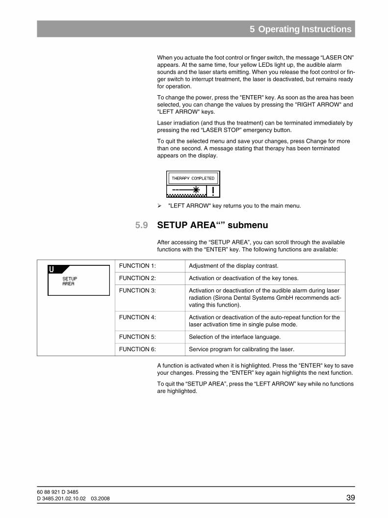
5.9 SETUP AREA“” submenu
After accessing the “SETUP AREA”, you can scroll through the available functions with the “ENTER” key. The following functions are available:
A function is activated when it is highlighted. Press the "ENTER" key to save your changes. Pressing the “ENTER” key again highlights the next function.
To quit the “SETUP AREA”, press the “LEFT ARROW” key while no functions are highlighted.
FUNCTION 1: Adjustment of the display contrast.
FUNCTION 2: Activation or deactivation of the key tones.
FUNCTION 3: Activation or deactivation of the audible alarm during laser radiation (Sirona Dental Systems GmbH recommends acti-vating this function).
FUNCTION 4: Activation or deactivation of the auto-repeat function for the laser activation time in single pulse mode.
FUNCTION 5: Selection of the interface language.
FUNCTION 6: Service program for calibrating the laser.
60 88 921 D 3485D 3485.201.02.10.02 03.2008 39
6 Indications, contraindications and medical precautions
6 Indications, contraindications and medical precautions
6.1 Indications
Compared to conventional dental surgery, treatment with the SIROLaser offers the following advantages: less invasive, minimum cell destruction, less bleeding, better coagulation, negligible post-operative edema. Treatment with the laser is low-pain and not pain-free. We recommend using anesthetics if necessary. The SIROLaser may only be operated by trained and qualified personnel.
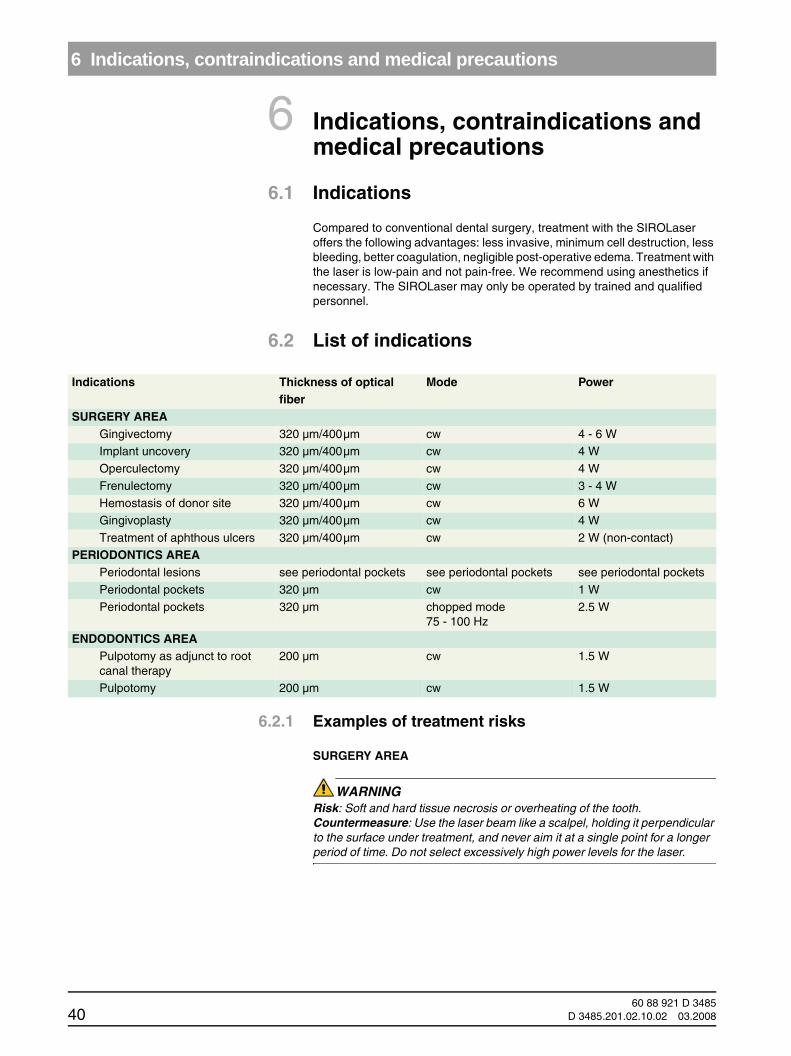
6.2 List of indications
6.2.1 Examples of treatment risks
SURGERY AREA
WARNING Risk: Soft and hard tissue necrosis or overheating of the tooth.Countermeasure: Use the laser beam like a scalpel, holding it perpendicular to the surface under treatment, and never aim it at a single point for a longer period of time. Do not select excessively high power levels for the laser.
Indications Thickness of optical fiber
Mode Power
SURGERY AREAGingivectomy 320 µm/400µm cw 4 - 6 WImplant uncovery 320 µm/400µm cw 4 W
Operculectomy 320 µm/400µm cw 4 W
Frenulectomy 320 µm/400µm cw 3 - 4 WHemostasis of donor site 320 µm/400µm cw 6 W
Gingivoplasty 320 µm/400µm cw 4 W
Treatment of aphthous ulcers 320 µm/400µm cw 2 W (non-contact)PERIODONTICS AREA
Periodontal lesions see periodontal pockets see periodontal pockets see periodontal pockets
Periodontal pockets 320 µm cw 1 W
Periodontal pockets 320 µm chopped mode75 - 100 Hz
2.5 W
ENDODONTICS AREAPulpotomy as adjunct to root canal therapy
200 µm cw 1.5 W
Pulpotomy 200 µm cw 1.5 W
60 88 921 D 348540 D 3485.201.02.10.02 03.2008
6 Indications, contraindications and medical precautions
båÖäáëÜ
båÖäáëÜ
PERIODONTICS AREA
WARNING Risk: Minor necrosis or scarring of the radicular area.Countermeasure: When working in periodontal pockets, always aim the laser parallel to, i.e. never perpendicular to, the roots. Run the distal end of the opti-cal fiber over the entire inner surface of the periodontal pocket.
6.3 ContraindicationsAt present, no contraindications are known for the use of therapeutic lasers in dentistry with devices of the same power and wavelength as the SIROLaser.
6.4 Precautions
WARNING Never direct the laser beam or the aiming beam toward a person's eye or thy-roid gland.
WARNING The eyes of patients, assistants and dentists must always be protected with the laser protective goggles provided with the unit, even when only the aiming beam is active. Special protective goggles are available for eyeglass wearers.
60 88 921 D 3485D 3485.201.02.10.02 03.2008 41

7 Cleaning and sterilization
7 Cleaning and sterilizationFollowing treatment, switch off the laser and disconnect the power cord from the power supply.
WARNING The dental fibers, handpieces and tips are supplied nonsterile. You must clean, disinfect and sterilize these products prior to first use and prior to each subsequent use.
WARNING Disinfect the finger switch prior to the first use and prior to each subsequent use.
Laser protective goggles
Before cleaning the laser protective goggles, please read and observe the instructions for use provided by the manufacturer and attached to the goggles in the case.
7.1 Cleaning
NOTICE iManual cleaning must always be combined with disinfection.
NOTICE iAll tissue residues must be removed from the optical fiber before it is detached from the handpiece. This prevents internal contamination of the tip.
Following treatment:
Optical fiber
CAUTION Reattach the black protective cap to the (laser) end of the connector before taking any hygienic measures.
Remove the optical fiber from the handpiece.
Notch it approx. 4 cm from the distal end of the optical fiber. The notch must be made perpendicular to the axis of the optical fiber.
Remove approx. 4 cm of the sheath if necessary (see Chapter 4.7.4, page 27).
The take-up reel and the optical fiber must be disinfected first.
After it is removed from the reel, the optical fiber can be cleaned with a suitable brush under running water (of at least drinking water quality).
Handpiece
Remove the tip from the handpiece.
Disassemble the handpiece by unscrewing the two threaded joints.Clean the handpiece and reusable tip with a suitable brush under running water. Clean the distal end of the optical fiber using a soft, damp cloth.If a finger switch is installed, remove it as described in Chapter 4.6
60 88 921 D 348542 D 3485.201.02.10.02 03.2008
7 Cleaning and sterilization
båÖäáëÜ
båÖäáëÜ
Installation (Page 21).
Fiber cutter
Clean the fiber cutter in an ultrasonic bath or with a suitable brush under running water.
7.2 DisinfectionDisinfect the following parts using spray or wipe disinfection:
Optical fiber
Fiber cutter
Finger switchTake-up reel
SIROLaser (wipe disinfection only)
NOTICE iUse only disinfectants that comply with the requirements of your national au-thorities and whose bactericidal, fungicidal and virucidal properties have been tested and properly certified.
You can use for instance: MinutenSpray classic from Alpro; MinutenWipes from Alpro. In the USA: Cavicide® and CaviwipesTM.
Observe the instructions provided by the manufacturers of these disinfec-tants.
CAUTION The optical fiber may be damaged if it is seriously bent or improperly routed in-side the handpiece. This may constitute a health hazard for patients, dentists and dental assistants. The minimum bending radius of the optical fiber is 4.5 cm (diameter: 9 cm). Be careful not to pinch or tear the optical fiber when in-serting or cleaning it.
7.3 Sterilization
WARNING You must sterilize the handpiece, the tips and the fiber prior to first use and pri-or to each subsequent use.
NOTICE iRemove any possible water residues from the handpiece, the fiber cutter and the reusable tips.
The disassembled handpiece, tips, coil and fiber must be sterilized only in autoclaves with saturated water vapor at 132°C - 135°C (269.6° F - 275°F), 3 min. holding time (1.87 bar - 2.13 bar; 27.12 psi - 33.88 psi overpressure).
The take-up reel and optical fiber can be sterilized 50 times.
60 88 921 D 3485D 3485.201.02.10.02 03.2008 43

7 Cleaning and sterilization
CAUTION The optical fiber may be damaged if it is seriously bent or improperly routed in-side the handpiece. This may constitute a health hazard for patients, dentists and dental assistants. The minimum bending radius of the optical fiber is 4.5 cm (diameter: 9 cm). Be careful not to pinch or tear the optical fiber when in-serting or cleaning it.
CAUTION Pls. always cover the proximal end of the fiber with the special protection cap for sterilization. Use only this special protection cap for sterilization!
Approved for sterilization are steam sterilizers that fulfill the requirements of EN 13060: 2004 and are suitable for the sterilization of dental handpieces, e.g. Midmark M9 UltraClaveTM Steam Sterilizer (M9-02X).
7.4 Cleaning the laser unit and the finger switchUse a dry, soft cloth to remove dust from the SIROLaser. More stubborn spots can be removed with a damp cloth.
You can disinfect the SIROLaser using any of the products that are commonly used to disinfect medical electrical equipment, e.g. MinutenSpray -classic, CAVICIDE® or Caviwipe.
CAUTION Spray disinfection may allow liquids to penetrate into the laser unit! The SIROLaser can only be disinfected by wiping.
Observe the instructions provided by the manufacturers of these disinfec-tants.
Disinfect the finger switch by spray or wipe disinfection.
You can use for instance: MinutenSpray classic from Alpro; MinutenWipes from Alpro. In the USA: Cavicide® and CaviwipesTM.
Observe the instructions provided by the manufacturers of these disinfec-tants.
CAUTION Be careful not to damage the optical fiber when removing the finger switch.
WARNING For further safety measures, see Chapter 1.3.
CAUTION The SIROLaser unit cannot be sterilized.
CAUTION The handpieces and reusable tips must be sterilized after each treatment.
60 88 921 D 348544 D 3485.201.02.10.02 03.2008
8 Maintenance and service
båÖäáëÜ
båÖäáëÜ
8 Maintenance and service
8.1 Calibration check
WARNING You must wear the supplied laser protective goggles during the entire calibration procedure.
The following section describes the procedure for calibrating the SIROLaser.
We recommend performing this check at least once a week.
In order to enable exact inspection of the performance and flawless functioning of your SIROLaser unit, we recommend performing calibration at three different power levels:
1 W3 W
5 W
The SIROLaser performs a self-calibration. During this procedure, the system checks that the laser emission parameters are correct. We recommend that you check these values using a suitable external measuring instrument at least every six months. If the measurement readings indicate a wavelength of 970 nm +/- 15 nm, a power of 0.5 to 7 W and a resolution of 5% or higher, the calibration is correct.
8.1.1 Callibration check without an external power meter
WARNING You must wear the supplied laser protective goggles during the entire calibration procedure.
Connect an optical fiber to the SIROLaser.
Point the optical fiber in the air in a controlled direction.
Wear the laser protective goggles and verify that the entrance to the room where the calibration is being performed is controlled by an interlock device or is locked.
Switch on the SIROLaser and select the “SETUP AREA”.
Select “SERVICE”.
The first test (1 W) is highlighted.
Use the “RIGHT ARROW” key to select the test you want to perform (1 W, 3 W, 5 W). Press the “LEFT ARROW” key to end the test.
Test for 1 W
Release laser radiation with the foot control or finger switch until the message OK appears.
Test for 3 W
Release laser radiation again until the message OK appears.
Test for 5 W
Release laser radiation again until the message OK appears.
Quit the calibration menu by pressing the “LEFT ARROW” key.
60 88 921 D 3485D 3485.201.02.10.02 03.2008 45
8 Maintenance and service
If you performed the test correctly and got an OK message for all three tests, the laser unit has been successfully calibrated.
8.1.2 Calibration check using an external power meter
Required power meter: Tested, traceable power meter capable of measuring a power level of 10 watts.
WARNING You must wear the supplied laser protective goggles during the entire calibration procedure.
Connect an optical fiber to the SIROLaser.
Aim the optical fiber at the measuring sensor of the power meter. Maintain a distance of at least 20 mm between the optical fiber and the surface of the measuring sensor. This way you can prevent possible damage to the power meter which might otherwise result from the small diameter of the optical fiber and the correspondingly high energy density.
Wear the laser protective goggles and verify that the entrance to the room where the calibration is being performed is controlled by an interlock device or is locked.
Switch on the SIROLaser and select the “SETUP AREA”.
Select “SERVICE”.
Make sure that the optical fiber is cut carefully and that the laser beam projects a red circle. The circle must be as well defined as possible.
The first test (1 W) is highlighted.
Use the “RIGHT ARROW” key to select the test you want to perform (1 W, 3 W, 5 W). Press the “LEFT ARROW” key to end the test.
Test for 1 W
Release laser radiation with the foot control or finger switch until the message OK appears. Check whether the measured result is within the permissible range of 1 W +/-20%.
Test for 3 W
Release laser radiation again until the message OK appears. Check whether the measured result is within the permissible range of 3 W +/-20%.
Test for 5 W
Release laser radiation again until the message OK appears. Check whether the measured result is within the permissible range of 5 W +/-20%.
Quit the calibration menu by pressing the “LEFT ARROW” key.
If the test procedure runs without errors, the message OK will appear for each test, and the values measured on the power meter will be within the permis-sible range. In this case, the unit has been successfully calibrated.
60 88 921 D 348546 D 3485.201.02.10.02 03.2008
8 Maintenance and service
båÖäáëÜ
båÖäáëÜ
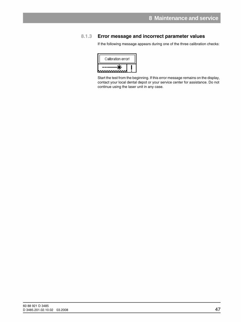
8.1.3 Error message and incorrect parameter values
If the following message appears during one of the three calibration checks:
Start the test from the beginning. If this error message remains on the display, contact your local dental depot or your service center for assistance. Do not continue using the laser unit in any case.
60 88 921 D 3485D 3485.201.02.10.02 03.2008 47

8 Maintenance and service
If the values measured during one of the three calibration checks lie outside of the permissible range, please proceed according to the following flow chart:
Start
One of the three measured values is
outside the permissible range,
Has the optical fiber been prepared
properly?
Cut the end of the optical fiber so that an exact circle becomes
visible.
Is the optical fiber aimed exactly at the
sensor range?
Aim the optical fiber at the measuring sensor from a distance of at least 2 cm, making sure that the red circle is located inside the
sensor range.
The power meteris switched on and
set so that a power of up to 10 W can be
correctly measured at 970 nm ± 10 nm.
Set the power meter to a measuring range of max. 10 W (upper end of scale)
and a wavelength of 970 nm +/– 15 nm.
Does the error persist when repeating
the measure-ment?
Sirona Dental Systems LLC,
Dental Sales or authorized
service center
NO
YES
NO
YES
NO
YES
NO
OK
60 88 921 D 348548 D 3485.201.02.10.02 03.2008

8 Maintenance and service
båÖäáëÜ
båÖäáëÜ
8.2 Safety checks
The following safety checks must be performed every 24 months by a quali-fied service engineer:
Visual inspection of the unit and its accessories for mechanical damage that might impair operationGeneral function check
Check of the visual and audible indicators
NC and SFC earth leakage current acc. to IEC 601NC and SFC housing leakage current acc. to IEC 601
NC and SFC patient leakage current acc. to IEC 601
Laser power measurement with calibrated measuring equipment in the range between 0.5 W and 7 W
8.3 Maintenance
The SIROLaser does not require special maintenance. In case of malfunc-tioning, see chapter Technical support, repair and testing. However, Sirona Dental Systems GmbH recommends taking the following actions at regular intervals:
Action Distance ResponsibleCheck of the optical fiber (see chapter 4.7 "Connecting the optical fiber" on page 21)
before each treatment session
Operator
Calibration of the laser (see chapter 8.1 "Calibration check" on page 45)
weekly Operator
Safety checks every 2 years 800-659-5977
Sirona Dental Systems LLC4835 Sirona DriveSuite 100Charlotte, NC 28273USA
or your local dealerFDA 21 CFR 1040.11 requires a manual for a medical Class IV laser to contain a calibration pro-cedure and schedule.
The user shall perform the calibration procedure at least every six months with the help of a suit-able external power meter, for power measure-ments at a wavelength of 970 nm +/– 10 nm, a power between 0.5 W and 7 W and a resolution better than 5% that has been properly calibrated.
Equipment needed: Certified traceable power meter that can measure a minimum of 10 watts
This procedure is outlined below. If the user is not able to perform this procedure, please contact the Sales Department of Sirona Dental Systems LLC to arrange to have the laser sent to us to perform this procedure.
at least every six months.
800-659-5977
Sirona Dental Systems LLC4835 Sirona DriveSuite 100Charlotte, NC 28273USA
or your local dealer
60 88 921 D 3485D 3485.201.02.10.02 03.2008 49

8 Maintenance and service
NOTICE iIf national or local legal regulations require additional safety checks for your la-ser unit, these regulations must be complied with and the corresponding checks must be performed.
The manufacturer accepts responsibility for the safety of the laser unit only if the following requirements are fulfilled:
Modifications of the laser unit or repair work must be performed by autho-rized personnel.
The electrical installations in the rooms where the SIROLaser is used must fulfill the applicable legal requirements.
The unit must be used in compliance with the instructions provided in the present manual.
8.4 Troubleshooting of simple defectsIn case of malfunctioning, proceed as follows:
Check the connection of the power cord.
Check the connection of the interlock device.
Check the connection of the optical fiber.
Be sure that all operational steps have been carried out correctly.
Check the connection of the foot control.
8.5 Technical support, repair and testing
Sirona provides technical information on the repair of individual components only to authorized dealers and only after conducting an advanced training course for their technical personnel. Please contact your local dental depot or an authorized Customer Service Department for technical support.
The laser unit may be sent in for repair or for safety inspection only in its orig-inal packaging, including all accessories. Disinfect the laser unit and sterilize the accessories according to the relevant instructions for use prior to ship-ment.
60 88 921 D 348550 D 3485.201.02.10.02 03.2008

9 Technical data
båÖäáëÜ
båÖäáëÜ
9 Technical data
Laser system Class IV (according to IEC 60825-1: 2003) and according to 21 CFR 1040.10 and 1040.11
Device classification Class IIb (according to Council Directive 93/42/EEC)
IP degree of protection Laser unit: IP20; foot switch: IPX5
Wavelength 970 nm +/- 15 nm
Power max. approx. 7 W CW (optical)
Aiming beam 635 or 650 nm, max. 1 mW
Emission mode CW (continuous wave) or modulated 1 Hz to 10 kHz
Pulse (chopped mode) Single or repeated pulse
Pulse duration 100 ms to 60 s in 50 ms intervals
Optical fiber thickness 200, 320 and 400 mm, NA > = 0.22
Start Electrical foot control/finger switch plus electronic access key
Adapter External, 100 - 240 VAC, 50 - 60 Hz
Nominal power output: 48 VA
Insulation class Class 1, type B
Performance data displays on the graphic display
Dimensions 87 × 54 × 190 mm
Weight 450 g
Power supply The SIROLaser may only be operated with the Sinpro MPU50-105 power supply.
NOHD (nominal ocular hazarddistance)
approx. 1.5 m for 10 s radiation exposure of the unprotected eye (numerical aperture of the optical fiber NA = 0.22)
60 88 921 D 3485D 3485.201.02.10.02 03.2008 51
10 Manufacturer's declaration on electromagnetic compatibility
10 Manufacturer's declaration on electromagnetic compatibility
NOTICE iThe SIROLaser complies with all requirements for electromagnetic compati-bility according to IEC 60601-1-2: 2005.
10.1 Definitions
10.1.1 Emission (electromagnetic)
When electromagnetic energy is emitted by a source.
10.1.2 Interference immunity
The ability of a device or system to work without errors even if there is elec-tromagnetic interference.
10.1.3 Immunity level
The maximum level of a certain electromagnetic interference that affects a particular device or system, where the device or system remains operative with a certain level of performance.
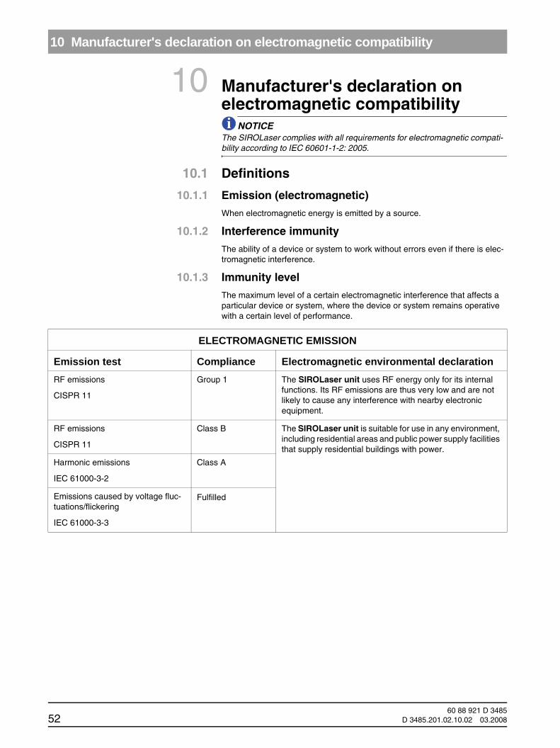
ELECTROMAGNETIC EMISSION
Emission test Compliance Electromagnetic environmental declarationRF emissions
CISPR 11
Group 1 The SIROLaser unit uses RF energy only for its internal functions. Its RF emissions are thus very low and are not likely to cause any interference with nearby electronic equipment.
RF emissions
CISPR 11
Class B The SIROLaser unit is suitable for use in any environment, including residential areas and public power supply facilities that supply residential buildings with power.
Harmonic emissions
IEC 61000-3-2
Class A
Emissions caused by voltage fluc-tuations/flickering
IEC 61000-3-3
Fulfilled
60 88 921 D 348552 D 3485.201.02.10.02 03.2008

10 Manufacturer's declaration on electromagnetic compatibility
båÖäáëÜ
båÖäáëÜ
Interference immunityThe SIROLaser is intended for use in the electromagnetic environment specified below. The user should ensure that it is used in such an environment.
Immunity test EN 60601-1-2 Inspection stage
Compliance level Electromagnetic environmental declaration
Electrostatic discharge (ESD)
EN 61000-4-2
± 6 kV contact dis-charge
± 8 kV contact dis-charge
± 6 kV contact dis-charge
± 8 kV contact dis-charge
The floors should be made of wood or concrete or finished with ceramic tiling. If the floor has a synthetic covering, the relative humidity should be at least 30 %.
Electrical fast transient/burst
EN 61000-4-4
± 2 kV for power supply lines
± 2 kV for power sup-ply lines
The power supply should be of a type that is customary in business environ-ments or in hospitals.
Overvoltage
EN 61000-4-5
± 1 kV push-pull ± 1 kV push-pull The power supply should be of a type that is customary in business environ-ments or in hospitals.
Voltage drops, brief power outages and voltage fluctua-tions on power supply input lines
EN 61000-4-11
< 5% UT
(> 95% drop of UT)
for 0.5 cycles
40% UT
(60% drop in UT)
for 5 cycles
70% UT
(30% drop in UT)
for 25 cycles
< 5% UT
(> 95% drop of UT)
for 5 seconds
< 5% UT
(> 95% drop of UT)
for 0.5 cycles
40% UT
(60% drop in UT)
for 5 cycles
70% UT
(30% drop in UT)
for 25 cycles
< 5% UT
(> 95% drop of UT)
for 5 seconds
The power supply should be of a type that is customary in business environ-ments or in hospitals.
If the user must be able to use the SIROLaser unit even in cases where the power supply is interrupted, we rec-ommend operating the SIROLaser unit with an uninterruptible power source or a battery.
Magnetic field of the power frequency
EN 61000-4-8
3 A/m 3 A/m The magnetic fields of the power fre-quency should move within a range that is normal for a typical commercially zoned or hospital site.
60 88 921 D 3485D 3485.201.02.10.02 03.2008 53
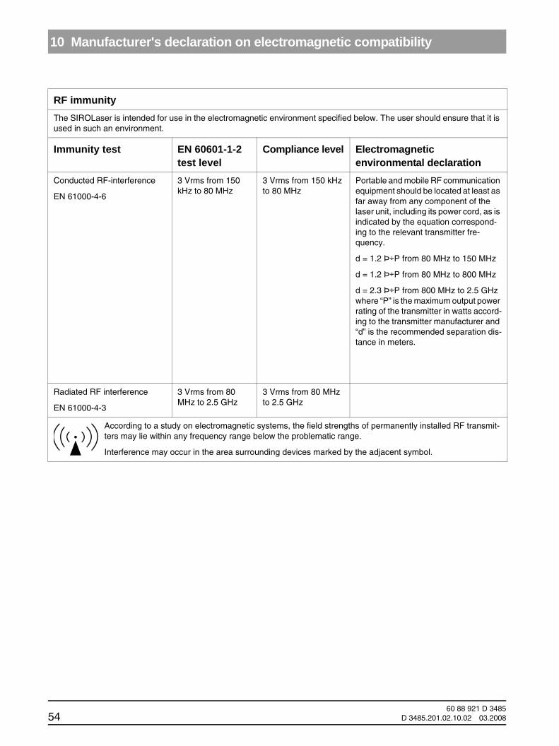
10 Manufacturer's declaration on electromagnetic compatibility
RF immunityThe SIROLaser is intended for use in the electromagnetic environment specified below. The user should ensure that it is used in such an environment.
Immunity test EN 60601-1-2test level
Compliance level Electromagnetic environmental declaration
Conducted RF-interference
EN 61000-4-6
3 Vrms from 150 kHz to 80 MHz
3 Vrms from 150 kHz to 80 MHz
Portable and mobile RF communication equipment should be located at least as far away from any component of the laser unit, including its power cord, as is indicated by the equation correspond-ing to the relevant transmitter fre-quency.
d = 1.2 Þ÷P from 80 MHz to 150 MHz
d = 1.2 Þ÷P from 80 MHz to 800 MHz
d = 2.3 Þ÷P from 800 MHz to 2.5 GHz where “P” is the maximum output power rating of the transmitter in watts accord-ing to the transmitter manufacturer and “d” is the recommended separation dis-tance in meters.
Radiated RF interference
EN 61000-4-3
3 Vrms from 80 MHz to 2.5 GHz
3 Vrms from 80 MHz to 2.5 GHz
According to a study on electromagnetic systems, the field strengths of permanently installed RF transmit-ters may lie within any frequency range below the problematic range.
Interference may occur in the area surrounding devices marked by the adjacent symbol.
60 88 921 D 348554 D 3485.201.02.10.02 03.2008

10 Manufacturer's declaration on electromagnetic compatibility
båÖäáëÜ
båÖäáëÜ
Recommended separation distances between portable and mobile RF communications equipment (transmitters) and the SIROLaserAlthough the SIROLaser is intended for use in an electromagnetic environment, the dispersion of the RF differences should nevertheless be checked. Electromagnetic interference can be prevented by maintaining a minimum distance between portable or mobile RF communications equipment and the SIROLaser. The following table shows what distance should be maintained by a communications device of a specific output.
Rated maximum output power of transmitter (in watts)
Separation distance according to transmitter frequency (in meters)
From 150 kHz to 80 MHz
d = 1.2 Þ÷P
From 80 MHz to 800 MHz
d = 1.2 Þ÷P
From 800 MHz to 2 GHz
d = 2.3 Þ÷P
0,01 0,12 0,12 0,23
0,1 0,38 0,38 0,73
1 1,2 1,2 2,3
10 3,8 3,8 7,3
100 12 12 23
Insofar as the maximum rated output power is not specified for certain transmitters, the recommended separation distance “d” in meters can be determined using the equation applicable to the frequency of the transmitter, where “P” is the maxi-mum output power rating of the transmitter in watts according to the transmitter manufacturer.
Remarks:
The separation distance for the higher frequency range applies at 80 MHz and 800 MHz.
(2) These directives are not always applicable. Electromagnetic propagation is affected by absorption and reflection from structures, objects, and people.
60 88 921 D 3485D 3485.201.02.10.02 03.2008 55

11 Appendix
11 Appendix11.1 Appendix B – Label positions
The following figures show the positions of the labels on the SIROLaser.
Figure 25: Label positions, top view
Figure 26: Label positions, rear view
Label 1a
Label 1 Label 4
Label 5
60 88 921 D 348556 D 3485.201.02.10.02 03.2008

11 Appendix
båÖäáëÜ
båÖäáëÜ
Figure 27: Label positions, bottom view
Label 2
Label 6
Label 3
Label 8
Label 7Label 9
Label 10
60 88 921 D 3485D 3485.201.02.10.02 03.2008 57
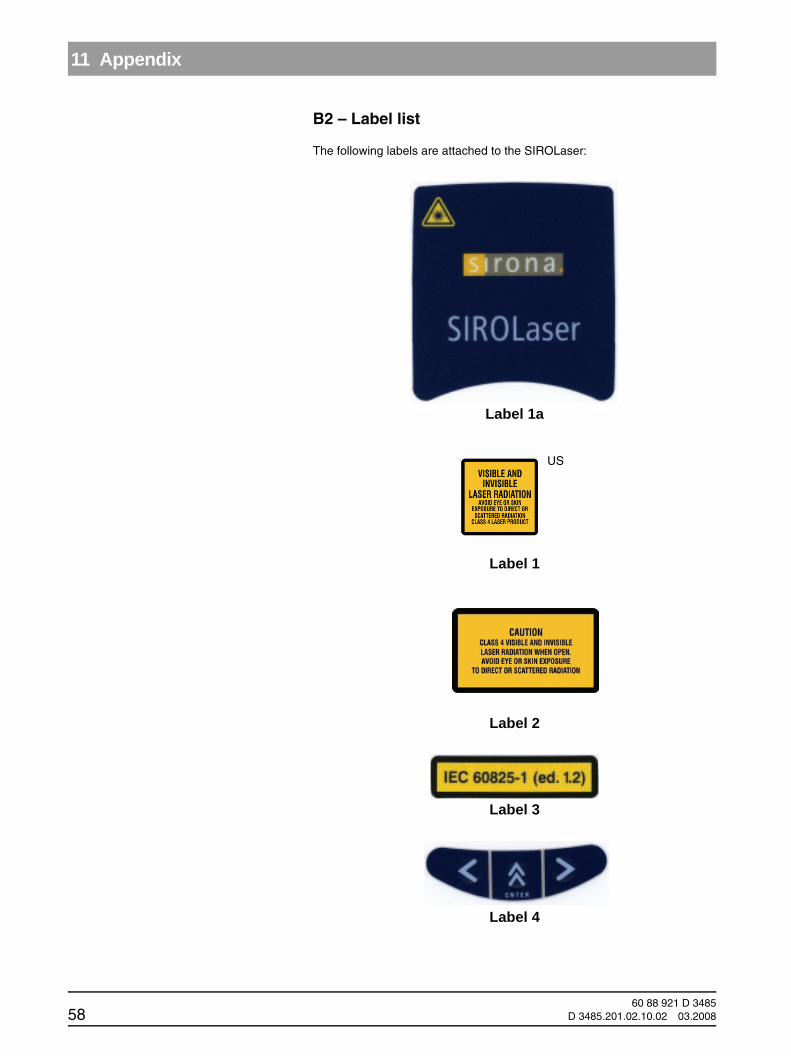
11 Appendix
B2 – Label list
The following labels are attached to the SIROLaser:
Label 1a
Label 1
Label 2
Label 3
Label 4
US
60 88 921 D 348558 D 3485.201.02.10.02 03.2008
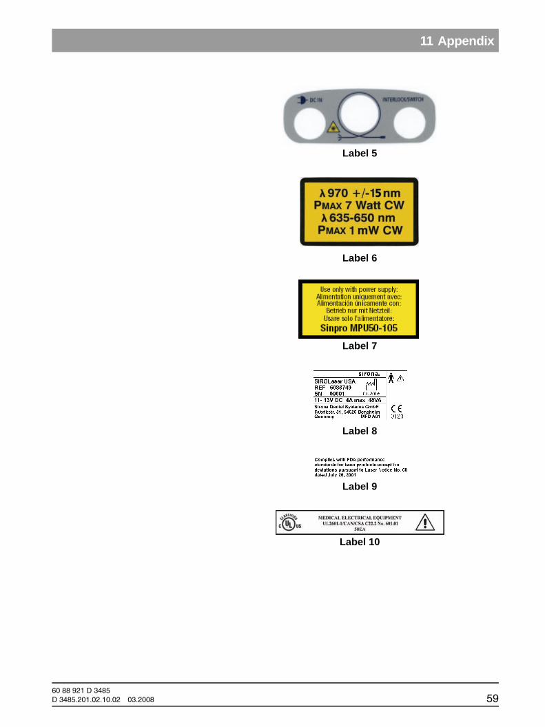
11 Appendix
båÖäáëÜ
båÖäáëÜ
Label 5
Label 6
Label 7
Label 8
Label 9
Label 10
60 88 921 D 3485D 3485.201.02.10.02 03.2008 59

tÉ=êÉëÉêîÉ=íÜÉ=êáÖÜí=íç=ã~âÉ=~åó=~äíÉê~íáçåë=ïÜáÅÜ=ã~ó=ÄÉ=êÉèìáêÉÇ=ÇìÉ=íç=íÉÅÜåáÅ~ä=áãéêçîÉãÉåíëK
«=páêçå~=aÉåí~ä=póëíÉãë=dãÄe=OMMRJOMMU péê~ÅÜÉW= ÉåÖäáëÅÜ= mêáåíÉÇ=áå=dÉêã~åóa=PQURKOMNKMOKNMKMO===MPKOMMU ûKJkêKW= NMT=UOU fãéêáã¨=Éå=^ääÉã~ÖåÉ
páêçå~=aÉåí~ä=póëíÉãë=dãÄeáå=íÜÉ=rp^W
c~Äêáâëíê~≈É=PNSQSOR=_ÉåëÜÉáãdÉêã~åóïïïKëáêçå~KÅçã
páêçå~=aÉåí~ä=póëíÉãë=ii`QUPR=páêçå~=aêáîÉI=pìáíÉ=NMM`Ü~êäçííÉI=k`=OUOTPrp^
lêÇÉê=kç SM=UU=VON=a=PQUR
: + + 49(0)6251/16-1616 in USA: : 800-659-5977F: + + 49(0)6251/16-1818 F: 888-297-8631
: [email protected] : [email protected] 6.00 – 18.00 CET 8am – 8pm EST