Embed Size (px)
Citation preview
PG-2000 user manual
(english)
14.05.2019
© PI 2019
Content1 A short introduction in PG-2000 .......................................................................................................7
1.1 Installation of the software .......................................................................................................81.2 De-installation of PG-2000 .......................................................................................................8
2 Overview of PG-2000 .......................................................................................................................82.1 Treatment of blocks ..................................................................................................................9
2.1.1 Treatment of blocks of a S5D-file .....................................................................................92.1.2 Treatment of blocks in the PLC ........................................................................................9
2.2 Interesting things about the block list .......................................................................................92.3 Force Variables/Force Outputs ................................................................................................102.4 The Statement List-Editor .......................................................................................................11
2.4.1 STL-Editor for blocks .....................................................................................................112.4.2 STL-Editor for comment blocks and symbols list ..........................................................12
2.5 CSF(S5) / FBD(S7) - Editor ...................................................................................................122.5.1 CSF(S5) / FBD(S7) - palette elements ............................................................................14
2.6 LAD-Editor .............................................................................................................................172.6.1 LAD-palette elements .....................................................................................................18
2.7 Cross-Reference, program-structure and I/Q/F-List ...............................................................212.7.1 Cross-reference-rolls .......................................................................................................212.7.2 The structure of the program ...........................................................................................242.7.3 I/Q/F-List ........................................................................................................................25
2.8 Other .......................................................................................................................................262.8.1 Datalogger .......................................................................................................................26
2.8.1.1 Datalogger Graphic settings ....................................................................................292.8.1.2 Autostart Datalogger ................................................................................................30
2.8.2 Context sensitive Help ....................................................................................................323 The Menu of PG-2000 ....................................................................................................................32
3.1 Commands in the menu File ...................................................................................................323.1.1 Create a new file ..............................................................................................................333.1.2 Open a file .......................................................................................................................333.1.3 Close a file ......................................................................................................................343.1.4 Save a file ........................................................................................................................343.1.5 Save a file as ...................................................................................................................343.1.6 Printer configuration .......................................................................................................353.1.7 Print .................................................................................................................................363.1.8 Hotkeys ...........................................................................................................................373.1.9 Exit the program ..............................................................................................................37
3.2 Commands in the menu Window ............................................................................................373.2.1 Cascade ...........................................................................................................................373.2.2 Tile horizontal .................................................................................................................373.2.3 Arrange symbols .............................................................................................................383.2.4 Hotkeys ...........................................................................................................................383.2.5 More Windows ................................................................................................................38
3.3 Commands in the menu Help ..................................................................................................383.3.1 Help function keys ..........................................................................................................383.3.2 Contents ..........................................................................................................................393.3.3 To use Help ......................................................................................................................393.3.4 Introduction .....................................................................................................................393.3.5 About PG-2000 ...............................................................................................................39
Handbook PG-2000 Page 2 of 126
3.4 Commands in the menu Options .............................................................................................393.4.1 Memory address output ...................................................................................................403.4.2 Commands in Symbols file... ..........................................................................................40
3.4.2.1 Symbols file ... New ................................................................................................403.4.2.2 Symbols file... Open ................................................................................................403.4.2.3 Symbols file..., Hotkeys ..........................................................................................40
3.4.3 Functions for Symbols file ..............................................................................................413.4.3.1 Symbols ...................................................................................................................413.4.3.2 View all symbols files .............................................................................................413.4.3.3 View absolute operands ...........................................................................................413.4.3.4 Symbols comment ...................................................................................................413.4.3.5 Symbols & absolute operands .................................................................................41
3.4.4 Footer file... .....................................................................................................................413.4.5 _________________ .......................................................................................................41
3.4.5.1 Footer file ... New ....................................................................................................423.4.5.2 Footer file ... Open ...................................................................................................423.4.5.3 Footer file... Hotkeys ...............................................................................................42
3.4.6 Use reference file ............................................................................................................423.4.7 Select a reference file ... ..................................................................................................423.4.8 Printer configuration for output ... ..................................................................................433.4.9 Configurations .................................................................................................................453.4.10 Font ...............................................................................................................................513.4.11 Colors ............................................................................................................................523.4.12 SEQ -> STL ...................................................................................................................533.4.13 Language .......................................................................................................................533.4.14 Interfaces .......................................................................................................................53
3.4.14.1 Select PG-Path .......................................................................................................553.4.14.1.1 inc. PG-Bus ....................................................................................................553.4.14.1.2 PG-Path selection ...........................................................................................56
3.4.15 Address of the S-Flags in the Memory of the PLC .......................................................573.5 Commands in the menu PLC-Functions .................................................................................58
3.5.1 Start PLC .........................................................................................................................583.5.2 Stop PLC .........................................................................................................................583.5.3 Compress PLC ................................................................................................................583.5.4 Delete PLC ......................................................................................................................593.5.5 Output PLC-Info .............................................................................................................593.5.6 Output memory configuration .........................................................................................593.5.7 Output memory contents .................................................................................................593.5.8 Force-Variables ...............................................................................................................603.5.9 Force-Outputs ..................................................................................................................603.5.10 Start status block ...........................................................................................................613.5.11 Stop status block ............................................................................................................613.5.12 ISTACK .........................................................................................................................61
3.5.12.1 Istack (PLC 95U/100U/115U) ...............................................................................613.5.12.2 Istack (PLC 135U/155U) .......................................................................................643.5.12.3 Istack (PLC 135 PLC) ...........................................................................................683.5.12.4 Istack ( PLC 150 A ) ..............................................................................................713.5.12.5 Istack (PLC 155U) .................................................................................................73
3.5.13 BSTACK .......................................................................................................................763.6 Commands in the menu View .................................................................................................77
Page 3 of 126 Handbook PG-2000
3.6.1 Toolbar ............................................................................................................................783.6.2 Status bar .........................................................................................................................783.6.3 Zoom ...............................................................................................................................793.6.4 Palette ..............................................................................................................................793.6.5 Segment comment ...........................................................................................................793.6.6 Statement List Programming (STL) ................................................................................803.6.7 CSF(S5) / FBD(S7) .........................................................................................................803.6.8 Ladder Logic Programming (LAD) ................................................................................80
3.7 Commands in the menu STL- / DOC- / Symbolic-Editor Search ..........................................803.7.1 Search ..............................................................................................................................813.7.2 Replace ............................................................................................................................813.7.3 Search/Repeat again ........................................................................................................823.7.4 Search double absolute-operands .............................................................................................823.7.5 Search double symbols-operand .....................................................................................823.7.6 View first/second .............................................................................................................833.7.7 Goto segment ..................................................................................................................833.7.8 Goto address ....................................................................................................................833.7.9 Goto block begin .............................................................................................................833.7.10 Goto block end ..............................................................................................................833.7.11 Goto the next segment ...................................................................................................833.7.12 Goto the segment before ...............................................................................................833.7.13 Insert segment ...............................................................................................................843.7.14 Delete segment ..............................................................................................................843.7.15 Goto begin block ...........................................................................................................843.7.16 Goto block end ..............................................................................................................84
3.8 Commands in the STL/DOC/Symbols-Editor-menu Edit ......................................................843.8.1 Block begin .....................................................................................................................843.8.2 Block end ........................................................................................................................853.8.3 Unmark blocks ................................................................................................................853.8.4 Cut out .............................................................................................................................853.8.5 Copy ................................................................................................................................853.8.6 Paste ................................................................................................................................853.8.7 Delete ..............................................................................................................................853.8.8 Paste line .........................................................................................................................853.8.9 Delete line .......................................................................................................................853.8.10 Paste program line .........................................................................................................863.8.11 Delete program line .......................................................................................................863.8.12 Paste comment line .......................................................................................................863.8.13 Delete comment line .....................................................................................................863.8.14 Assort to absolute operands ...........................................................................................863.8.15 Assort to symbols operands ...........................................................................................863.8.16 SEG <-> LINE ..............................................................................................................86
3.9 Commands in the Force-Variable-menu Status ......................................................................863.9.1 Start cycles ......................................................................................................................873.9.2 Stop cycles ......................................................................................................................873.9.3 Send values to PLC .........................................................................................................873.9.4 Datalogger configuration ................................................................................................873.9.5 Datalogger .......................................................................................................................883.9.6 Block ...............................................................................................................................88
Handbook PG-2000 Page 4 of 126
3.10 Commands in the block list menu Mark ...............................................................................883.10.1 Mark all blocks ..............................................................................................................893.10.2 Mark all comment blocks ..............................................................................................893.10.3 Mark all MC5-blocks ....................................................................................................893.10.4 Unmark all blocks .........................................................................................................893.10.5 Unmark all comment blocks .........................................................................................893.10.6 Unmark all MC5-blocks ................................................................................................893.10.7 Change group marks .....................................................................................................893.10.8 Change block marks ......................................................................................................893.10.9 Last mark .......................................................................................................................903.10.10 Sum of the marked blocks ...........................................................................................90
3.11 Commands in the block list menu Block ..............................................................................903.11.1 New block .....................................................................................................................903.11.2 Edit ................................................................................................................................903.11.3 Goto block... ..................................................................................................................913.11.4 Transfer to .....................................................................................................................913.11.5 Rename block ................................................................................................................913.11.6 Delete block ...................................................................................................................913.11.7 Compare block ..............................................................................................................913.11.8 Print ...............................................................................................................................913.11.9 Print block-list ...............................................................................................................913.11.10 Search ..........................................................................................................................913.11.11 Replace ........................................................................................................................923.11.12 XRF list .......................................................................................................................923.11.13 I/Q/F-list ......................................................................................................................933.11.14 Program structure ........................................................................................................933.11.15 Rewire manual .............................................................................................................933.11.16 Rewire automatic .........................................................................................................943.11.17 DB-Mask .....................................................................................................................94
3.11.17.1 Peripheral Access in DB 1 ...................................................................................943.11.17.2 AG 135U parameters (CPU928, R-Prozessor) of DX 0 ......................................953.11.17.3 AG 155U parameters of DX 0 .............................................................................96
3.11.18 AG95F Diagnosis ........................................................................................................973.11.18.1 Messages ..............................................................................................................973.11.18.2 OnBoard - peripheral ...........................................................................................993.11.18.3 Signal group .........................................................................................................993.11.18.4 External Peripheral ............................................................................................1003.11.18.5 AG95F L1 ..........................................................................................................100
3.12 Commands in the XRF-list menu of the XRF-list window ................................................1013.12.1 Goto ... Section of the XRF-List .................................................................................1013.12.2 Editor - find XRF ........................................................................................................1013.12.3 Assort the XRF-list ......................................................................................................101
4 The Option S7 ...............................................................................................................................1025 The Option Controller ..................................................................................................................105
5.1 Introduction ...........................................................................................................................1055.2 The different modes ..............................................................................................................1055.3 The commands in the "Versioning" menu ............................................................................1055.4 Dialogs in the Controller .......................................................................................................106
5.4.1 Choose user ...................................................................................................................1065.4.2 New user .......................................................................................................................107
Page 5 of 126 Handbook PG-2000
5.4.3 Program settings ............................................................................................................1075.4.4 Project properties ..........................................................................................................1085.4.5 PLC module versions ....................................................................................................1085.4.6 Comment changes .........................................................................................................1095.4.7 Instant comment ............................................................................................................1105.4.8 Project history ................................................................................................................1115.4.9 Backup version ..............................................................................................................1125.4.10 Restore version ............................................................................................................113
6 The Option S5-Emu ......................................................................................................................1146.1 Structure ................................................................................................................................1146.2 The S5EMU Application - A short introduction ...................................................................1146.3 Error-Messages .....................................................................................................................117
7 PG-2000 and S5-Emu ...................................................................................................................1187.1 File open - connection ...........................................................................................................1187.2 Example of an Error-correction with S5Emu .......................................................................119
8 Help ..............................................................................................................................................1218.1 Help for Comparison ............................................................................................................1218.2 Help for Timer Functions ......................................................................................................1218.3 Help for Counter Functions ..................................................................................................1218.4 Help for Flip-Flop’s ..............................................................................................................1218.5 Help for Function Blocks ......................................................................................................1228.6 Help for Operands .................................................................................................................1228.7 Help for Input Parameters .....................................................................................................1238.8 Help for Goto Segment .........................................................................................................1238.9 Help for Output Parameters ..................................................................................................1238.10 Help for Force Outputs .......................................................................................................1238.11 Help for Force Variables .....................................................................................................1248.12 Help for View PLC Memory ...............................................................................................1248.13 Help for Error Messages .....................................................................................................1248.14 Help for S5-V5 ....................................................................................................................124
8.14.1 Function keys like S5-V5 ............................................................................................1248.14.2 Dialog Select Simatic S5 Program ..............................................................................1258.14.3 Dialog Settings ............................................................................................................1258.14.4 Dialog Symbol-Settings ..............................................................................................125
9 PG-2000 option "TeleService" .....................................................................................................125
Handbook PG-2000 Page 6 of 126
1 A short introduction in PG-2000 With the software for programming PG-2000 you are able to generate and handle S5D-files easily and comfortably.Every blocks of a opened S5D-file are displayed by the block list.You select the blocks to edit them for changing or for appending some new blocks.
S5D-files - save them on floppy-disk or hard-diskS5D-files - you are able to transmit to the PLC completely or only some parts of them. That means you transmit only the selected blocks.
Read the following: see chapter:Edit blocks of a S5D-file on hard-disk or on disk
With PG-2000 you edit the blocks on the PLC easily
by listing the block listby selecting and changing some blocks or appending some new blocks.transmitting these blocks back to the PLC or saving them on disk or hard-disk.
Read the following: see chapter:Edit the blocks on the PLC
You read some further information of the block list for example how you select and you mark blocks for to edit in the theme (chapter 2.2)
Interesting things about the block list
PG-2000 offers you to use the three effective tools for changing and appending blocks:
the STL-Editor (chapter 2.4)
Define your blocks in form of a Statement List Programming with this special editor.
the CSF(S5) / FBD(S7)-Editor
(chapter 2.5)
Generate your blocks with this graphic-editor in form of CSF(S5) / FBD(S7)
the LAD-Editor (chapter 2.6)
Generate your blocks with this graphic-editor in form of Ladder Logic Programming.
In the menu ”options” offers you to define the colors and the used font of each editor.You get further information of this and the other commands in the menu ”options” in the theme:see chapter: and see chapter:
Commands in the menu Options
PG-2000 with its ”function PLC” offers you different possibilities to observe or to influence easily and clearly the program service of the PLC.There you find for example functions for watching and controlling variables functions for compressing or deleting the PLC, functions for displaying the status of the PLC and so on. Read forfurther information see chapter:
Commands in the PLC-functions menu
If you need more detailed information of some windows, menus or buttons (of the tools for example) you get these information fast and easily by using the context-sensitive help function
Page 7 of 126 Handbook PG-2000
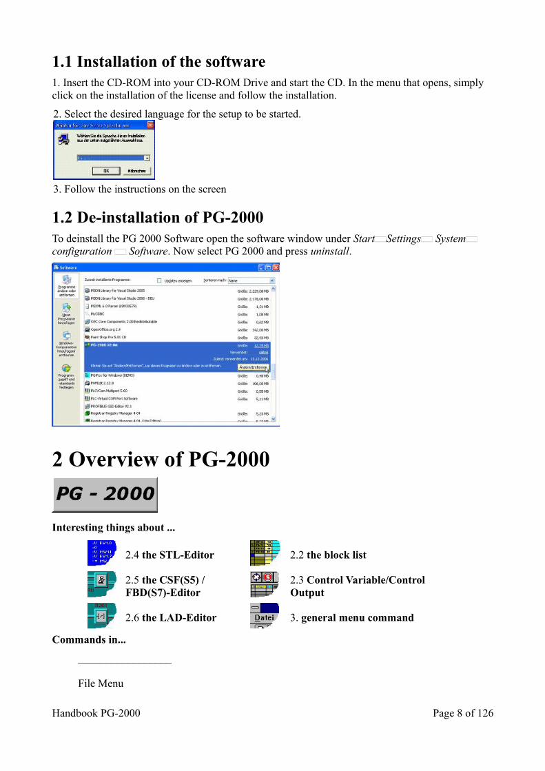
1.1 Installation of the software 1. Insert the CD-ROM into your CD-ROM Drive and start the CD. In the menu that opens, simply click on the installation of the license and follow the installation.
2. Select the desired language for the setup to be started.
3. Follow the instructions on the screen
1.2 De-installation of PG-2000 To deinstall the PG 2000 Software open the software window under Start Settings System configuration Software. Now select PG 2000 and press uninstall.
2 Overview of PG-2000
Interesting things about ...
2.4 the STL-Editor
2.2 the block list
2.5 the CSF(S5) / FBD(S7)-Editor
2.3 Control Variable/Control Output
2.6 the LAD-Editor
3. general menu command
Commands in...
_________________
File Menu
Handbook PG-2000 Page 8 of 126
View MenuPLC-Functions MenuOptions MenuWindow MenuHelp Menu_________________
2.1 Treatment of blocks
2.1.1 Treatment of blocks of a S5D-file
To open or create a file by calling the menu commands. If you have called the command File Open, you press the button File in the following window and choose the file you want in the next dialog.Now the block list shows you all blocks in the actual window. Move the mouse cursor onto the block you want to edit. This selected block will be displayed in a default editor by pressing Return, clicking twice with the mouse or calling the command block edit in the block-menu.
To save your file on floppy-disk or hard-disk by calling the command Save or Save as in the File-menu and you press the button File in the following dialog.
To transmit your file to the PLC by calling the command Save in the File-menu and you press the button PLC in the following dialog.
2.1.2 Treatment of blocks in the PLC
To open the PLC by calling the command File Open in the File-menu and pressing the button PLC in the following dialog.
Now the block list shows you all blocks in the actual window. Move the mouse cursor onto the block you want to edit. This selected block will be displayed in a default editor by pressing Return, clicking twice with the mouse or calling the command block edit in the block-menu.
To save your file on floppy-disk or hard-disk by calling the command Save or Save as in the File-menu and you press the button File in the following dialog.
To transmit your file to the PLC by calling the command Save as in the File-menu and pressing the button PLC in the following dialog.
2.2 Interesting things about the block list The block list displays the containing blocks in a list. To move inside this block list use the cursor keys.
Go to the first line of the list Key : POS1 (Home) Go one page back Key : Page up Go one line back Key : Arrow up Go one line forward Key : Arrow down Go one page forward Key : Page down
Go to the last line of the list TKey:
End
Page 9 of 126 Handbook PG-2000
Printing the block list
You can choose the blocks to be displayed by pressing the button in the block list toolbar.
You can search some blocks by using the block list's toolbar. You enter a block name, maybe not complete, and after each pressed key a corresponding block will be searched. The cursor will be set on the corresponding block if it is found.
You get into the input line by calling the command "Block/Goto block" in the menu (hot-key Crtl-F)or you enter directly the name you are looking for. If you call the command in the menu, the name you entered rests in the input line and can be edited. By entering the name directly each time a new line will be begun. You leave the input line by pressing the key ESC or RETURN.
The marked blocks are displayed in the left column in the list by showing the code ">>". You mark or unmark the block by pressing the button
or you calculate the sum of all the blocks, which are marked, by calling the command "Mark/Sum of the marked blocks". The sum is displayed in the input line of the block list's input line.
For further information about marking and unmarking see: see chapter:Commands in the menu PLC-Functions
You can apply the command in the menu Block to the marked blocks.for further information see: Commands in the block list's menu ”Block”
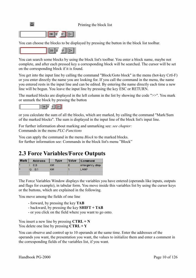
2.3 Force Variables/Force Outputs
The Force Variables Window displays the variables you have entered (operands like inputs, outputs and flags for example), in tabular form. You move inside this variables list by using the cursor keys or the buttons, which are explained in the following.
You move among the fields of one line
- forward, by pressing the key TAB- backward, by pressing the key SHIFT + TAB- or you click on the field where you want to go onto.
You insert a new line by pressing CTRL + NYou delete one line by pressing CTRL + Y
You can observe and control up to 10 operands at the same time. Enter the addresses of the operands you want, the presentation you want, the values to initialize them and enter a comment in the corresponding fields of the variables list, if you want.
Handbook PG-2000 Page 10 of 126
For example:
FW 15 KH F65A Temperature -Sensor 1
FW 27 KM 0111010100011111
Relay10-25
F 10.1 KM 1 In the KM-Format only Please do notice that the bit-operands can be displayed in KM-Format only.
Force Outputs differs from Force Variables like to follow:
• only the operands QD (double word output), QW (word output), QB (byte output) are allowed,• the PLC must be stopped otherwise the controlling is not possible,• the cycle is not available but the command Transfer to the PLC.
The commands in the Menu Status are placed at your disposal for transmitting the values, you have entered, or for observing the actual values in the PLC.
Finally you can save the operands, you have entered, including the newest value by using the commands Open and Save in the menu File.
With the toolbar you can choose the command out of the Status in the following order, from left to the right side.
start dataloggersend values to PLCstart cyclestop cycle
2.4 The Statement List-Editor
2.4.1 STL-Editor for blocks
For editing your block in the STL-Editor, first of all you have to move the cursor on the corresponding line. Then you choose the command Edit in the menu Block.You can also click twice with the mouse the corresponding line or press RETURN there. This selected block will be displayed on the editor that you choose as default.You choose the STL, CSF(S5) / FBD (S7) or LAD editor in the menu View or on the toolbar buttons. This is the following button:
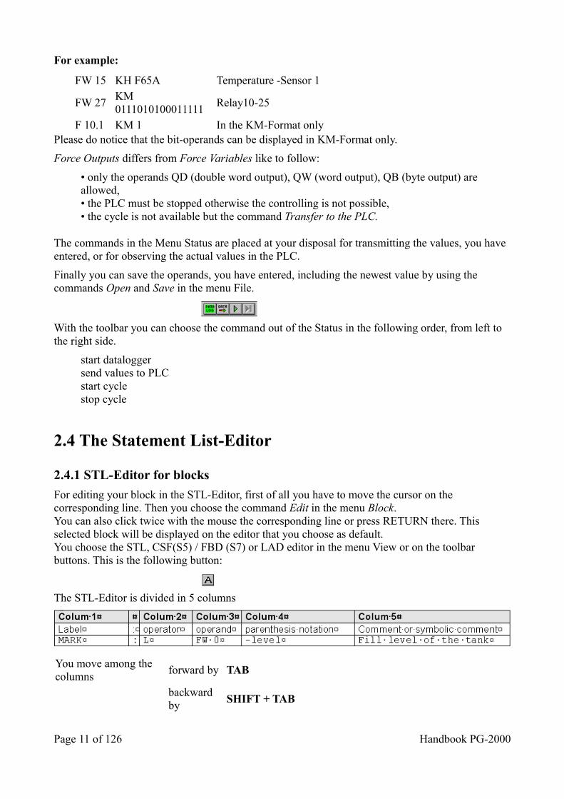
The STL-Editor is divided in 5 columns
You move among the columns
forward by TAB
backward by
SHIFT + TAB
Page 11 of 126 Handbook PG-2000
You insert a new line by pressing the keys CTRL + N or by calling the command Paste line in the STL-editor's menu Edit.You delete one line by pressing the keys CTRL + Y or by calling the command Delete line in the STL-editor's menu Edit.
See also: chapter 3.8 Commands in the STL/DOC/Symbols-Editor-menu Edit.
You insert a new segment like it is usual in STEP5. See the following to this:
1. Insert a new line on the desired position (Ctrl-N).2. Enter "***” in this new line.3. Confirm with ENTER. Thereon the previous segment will be closed and a new segment will be created.
• You do not have to set the operand and the operator in position. They will be entered automatically on the right position when you have pressed the key RETURN.• When you pressed RETURN a reasonableness test is started. If an error is detectedthe line is displayed in that color for errors, which can be defined in the menu Options-Colors• The major letters and small letters are not distinguished. They will be converted inmajor letters when you have pressed RETURN.• Labels have to be in column 1 and it is not allowed to name them with a blank as first char.• Comments must be in column 5.
If you want to display a block in the STL for which no DV-block (Reference Blocks) exists for the first time, you have to select a method for displaying the data in this dialog. Therefore you have to select one of the specified formats with the mouse or keyboard and confirm by clicking the OK-button. If you store the block in a file the DV-block will be created and stored automatically. This DV-block contains information about all formatting at the moment of saving. Naturally additional changes will be stored, too.
2.4.2 STL-Editor for comment blocks and symbols list
The STL-Editor for the comment blocks and the symbols list is a variant of the STL-Editor. It is divided and to employ in the same way as the STL-Editor.
There are difference in the construction of the menu Edit and Search:You get an explication of the modified commands in these menus by calling help about the commands.
2.5 CSF(S5) / FBD(S7) - Editor For editing your block in the CSF(S5) / FBD(S7) - Editor, first of all you have to move the cursor on the corresponding line. Then you choose the command Edit in the menu Block.You can also click twice with the mouse the corresponding line or press RETURN there. This selected block will be displayed on the editor which you choose as default.You choose the STL, CSF(S5) / FBD(S7) or LAD editor in the menu View or on the toolbar buttons. This is the following button:
The window rests empty if the block is not notable. You move inside the CSF(S5) / FBD(S7) -
Handbook PG-2000 Page 12 of 126
Editor by using the two scroll-bars of the window.
You insert a new segment after the actual segment by pressing the following button:
You move one segment up by pressing Ctrl - Page up or pressing the following button:
You move one segment down by pressing Ctrl - Page down or pressing the following button:
The following button will remove a segment, after a security-check:
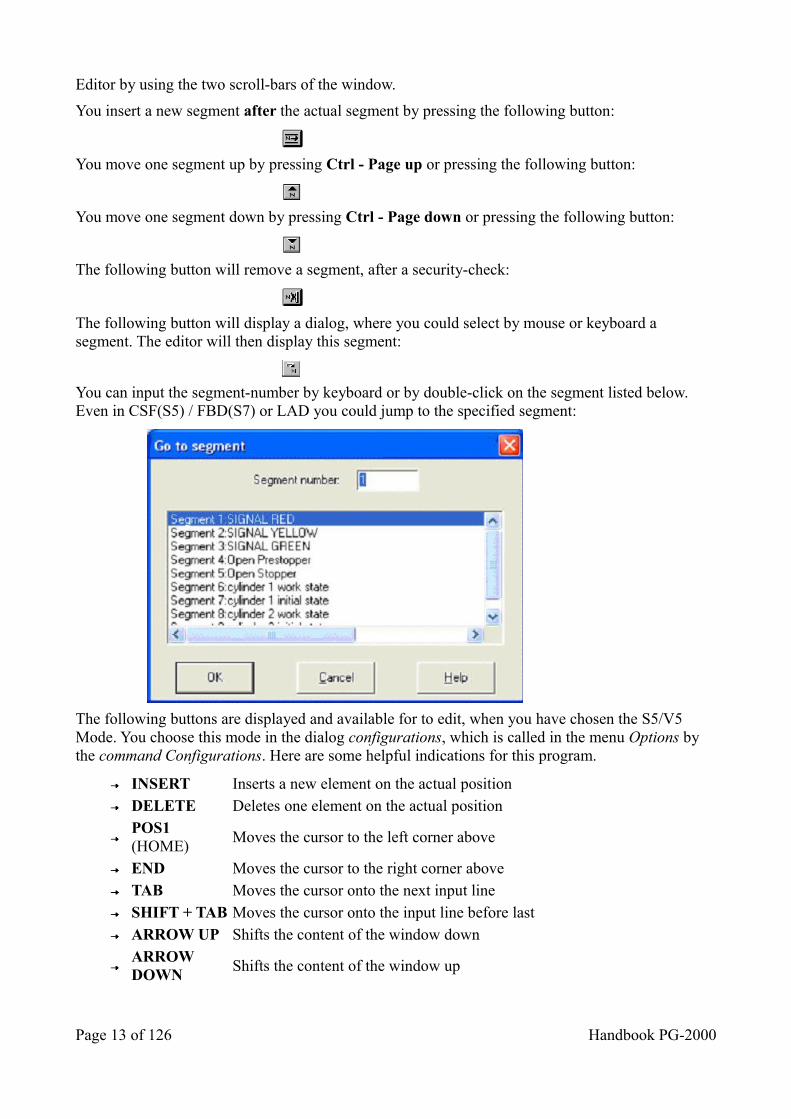
The following button will display a dialog, where you could select by mouse or keyboard a segment. The editor will then display this segment:
You can input the segment-number by keyboard or by double-click on the segment listed below. Even in CSF(S5) / FBD(S7) or LAD you could jump to the specified segment:
The following buttons are displayed and available for to edit, when you have chosen the S5/V5 Mode. You choose this mode in the dialog configurations, which is called in the menu Options by the command Configurations. Here are some helpful indications for this program.
INSERT Inserts a new element on the actual position DELETE Deletes one element on the actual position
POS1 (HOME)
Moves the cursor to the left corner above
END Moves the cursor to the right corner above TAB Moves the cursor onto the next input line SHIFT + TAB Moves the cursor onto the input line before last ARROW UP Shifts the content of the window down
ARROW DOWN
Shifts the content of the window up
Page 13 of 126 Handbook PG-2000
ARROW LEFT
Shifts the content of the window to the right
ARROW RIGHT
Shifts the content of the window to the left
2.5.1 CSF(S5) / FBD(S7) - palette elements
For inserting a new element, you have to choose the corresponding element of the palette with the mouse. Then you click the connection in which the element shall be inserted.
You also have the possibility to change an already placed element into a element of the same type. That means, you are able to change an AND-element into an OR-element, etc. The type of the element has to be the same as before. The following elements are available:
• AND/OR• Timer• Counter• Comparator• Set/Reset precedence• arithmetic with one operand• arithmetic with two operands• special functions without operands
For changing an element, you choose the new element in the palette and click on the old element to change it. You set the parameter or delete elements as it is explained aside the symbol below.
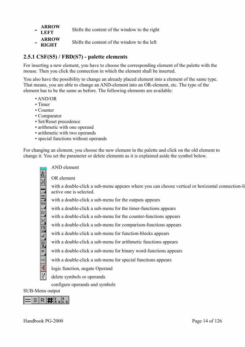
AND element
OR element
with a double-click a sub-menu appears where you can choose vertical or horizontal connection-lines, the active one is selected.
with a double-click a sub-menu for the outputs appears
with a double-click a sub-menu for the timer-functions appears
with a double-click a sub-menu for the counter-functions appears
with a double-click a sub-menu for comparison-functions appears
with a double-click a sub-menu for function-blocks appears
with a double-click a sub-menu for arithmetic functions appears
with a double-click a sub-menu for binary word-functions appears
with a double-click a sub-menu for special functions appears
logic function, negate Operand
delete symbols or operands
configure operands and symbols SUB-Menu output
Handbook PG-2000 Page 14 of 126
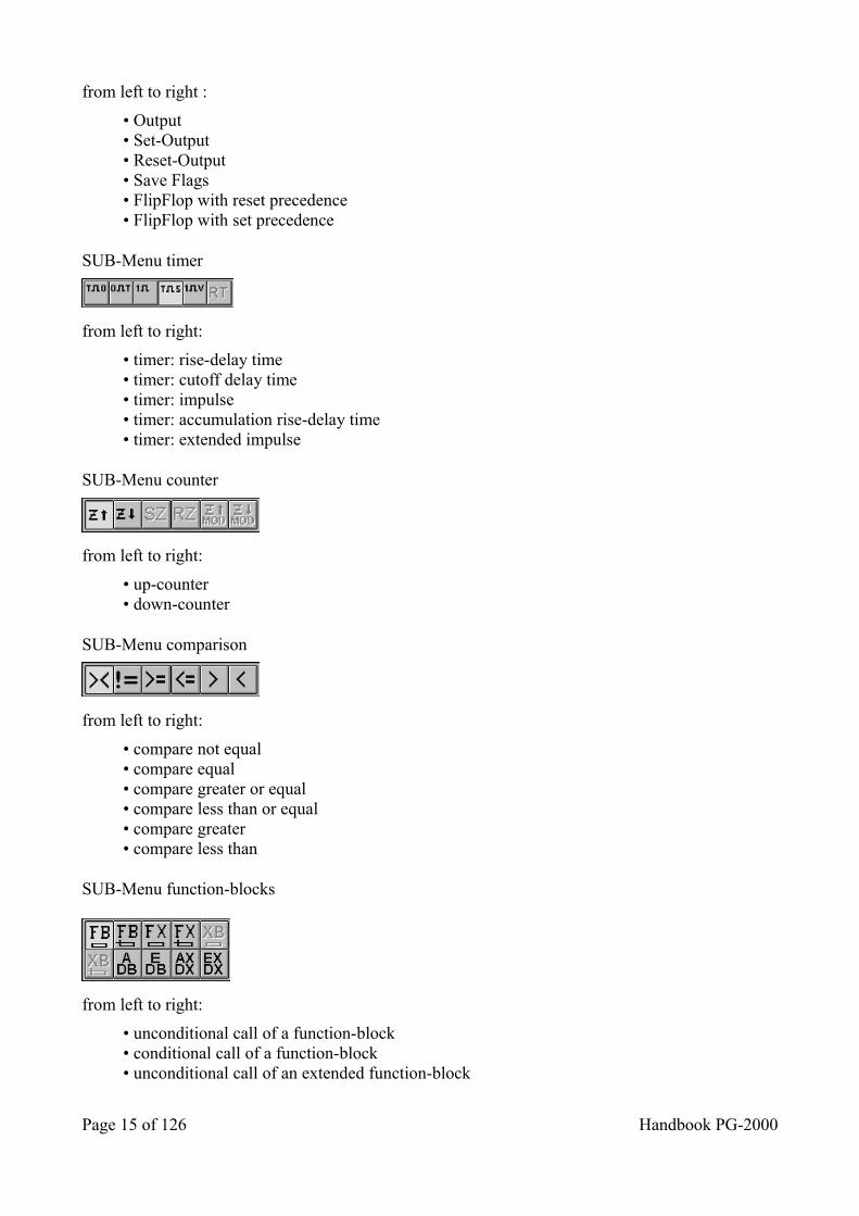
from left to right :
• Output• Set-Output• Reset-Output• Save Flags• FlipFlop with reset precedence• FlipFlop with set precedence
SUB-Menu timer
from left to right:
• timer: rise-delay time• timer: cutoff delay time• timer: impulse• timer: accumulation rise-delay time• timer: extended impulse
SUB-Menu counter
from left to right:
• up-counter• down-counter
SUB-Menu comparison
from left to right:
• compare not equal• compare equal• compare greater or equal• compare less than or equal• compare greater• compare less than
SUB-Menu function-blocks
from left to right:
• unconditional call of a function-block• conditional call of a function-block• unconditional call of an extended function-block
Page 15 of 126 Handbook PG-2000
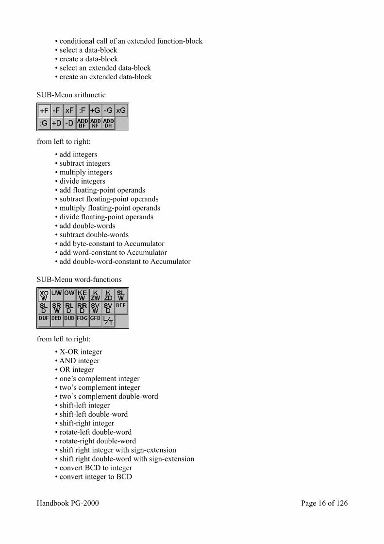
• conditional call of an extended function-block• select a data-block• create a data-block• select an extended data-block• create an extended data-block
SUB-Menu arithmetic
from left to right:
• add integers• subtract integers• multiply integers• divide integers• add floating-point operands• subtract floating-point operands• multiply floating-point operands• divide floating-point operands• add double-words• subtract double-words• add byte-constant to Accumulator• add word-constant to Accumulator• add double-word-constant to Accumulator
SUB-Menu word-functions
from left to right:
• X-OR integer• AND integer• OR integer• one’s complement integer• two’s complement integer• two’s complement double-word• shift-left integer• shift-left double-word• shift-right integer• rotate-left double-word• rotate-right double-word• shift right integer with sign-extension• shift right double-word with sign-extension• convert BCD to integer• convert integer to BCD
Handbook PG-2000 Page 16 of 126
• convert BCD to double-word• convert double-word to BCD• convert integer to floating-point• convert floating-point to integer• transfer word-operands
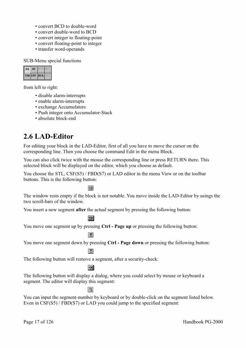
SUB-Menu special functions
from left to right:
• disable alarm-interrupts• enable alarm-interrupts• exchange Accumulators• Push integer onto Accumulator-Stack• absolute block-end
2.6 LAD-Editor For editing your block in the LAD-Editor, first of all you have to move the cursor on the corresponding line. Then you choose the command Edit in the menu Block.
You can also click twice with the mouse the corresponding line or press RETURN there. This selected block will be displayed on the editor, which you choose as default.
You choose the STL, CSF(S5) / FBD(S7) or LAD editor in the menu View or on the toolbar buttons. This is the following button:
The window rests empty if the block is not notable. You move inside the LAD-Editor by usings the two scroll-bars of the window.
You insert a new segment after the actual segment by pressing the following button:
You move one segment up by pressing Ctrl - Page up or pressing the following button:
You move one segment down by pressing Ctrl - Page down or pressing the following button:
The following button will remove a segment, after a security-check:
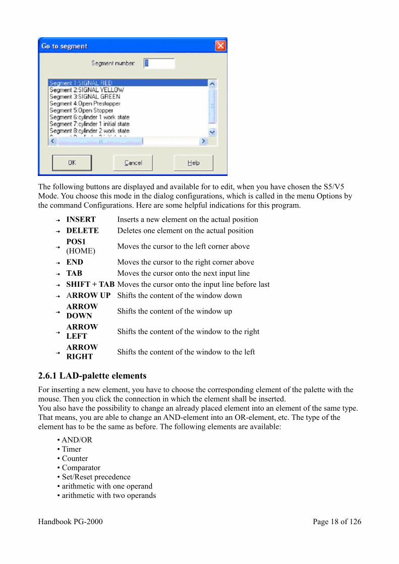
The following button will display a dialog, where you could select by mouse or keyboard a segment. The editor will display this segment:
You can input the segment-number by keyboard or by double-click on the segment listed below. Even in CSF(S5) / FBD(S7) or LAD you could jump to the specified segment:
Page 17 of 126 Handbook PG-2000
The following buttons are displayed and available for to edit, when you have chosen the S5/V5 Mode. You choose this mode in the dialog configurations, which is called in the menu Options by the command Configurations. Here are some helpful indications for this program.
INSERT Inserts a new element on the actual position DELETE Deletes one element on the actual position
POS1 (HOME)
Moves the cursor to the left corner above
END Moves the cursor to the right corner above TAB Moves the cursor onto the next input line SHIFT + TAB Moves the cursor onto the input line before last ARROW UP Shifts the content of the window down
ARROW DOWN
Shifts the content of the window up
ARROW LEFT
Shifts the content of the window to the right
ARROW RIGHT
Shifts the content of the window to the left
2.6.1 LAD-palette elements
For inserting a new element, you have to choose the corresponding element of the palette with the mouse. Then you click the connection in which the element shall be inserted.You also have the possibility to change an already placed element into an element of the same type. That means, you are able to change an AND-element into an OR-element, etc. The type of the element has to be the same as before. The following elements are available:
• AND/OR• Timer• Counter• Comparator• Set/Reset precedence• arithmetic with one operand• arithmetic with two operands
Handbook PG-2000 Page 18 of 126
• special functions without operands
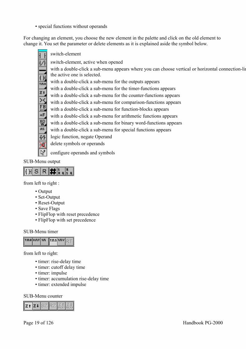
For changing an element, you choose the new element in the palette and click on the old element to change it. You set the parameter or delete elements as it is explained aside the symbol below.
switch-element
switch-element, active when opened with a double-click a sub-menu appears where you can choose vertical or horizontal connection-lines, the active one is selected. with a double-click a sub-menu for the outputs appears with a double-click a sub-menu for the timer-functions appears with a double-click a sub-menu for the counter-functions appears with a double-click a sub-menu for comparison-functions appears with a double-click a sub-menu for function-blocks appears with a double-click a sub-menu for arithmetic functions appears with a double-click a sub-menu for binary word-functions appears with a double-click a sub-menu for special functions appears logic function, negate Operand delete symbols or operands
configure operands and symbols
SUB-Menu output
from left to right :
• Output• Set-Output• Reset-Output• Save Flags• FlipFlop with reset precedence• FlipFlop with set precedence
SUB-Menu timer
from left to right:
• timer: rise-delay time• timer: cutoff delay time• timer: impulse• timer: accumulation rise-delay time• timer: extended impulse
SUB-Menu counter
Page 19 of 126 Handbook PG-2000
from left to right:
• up-counter• down-counter
SUB-Menu comparison
from left to right:
• compare not equal• compare equal• compare greater or equal• compare less than or equal• compare greater• compare less than
SUB-Menu function-blocks
from left to right:
• unconditional call of a function-block• conditional call of a function-block• unconditional call of an extended function-block• conditional call of an extended function-block• select a data-block• create a data-block• select an extended data-block• create an extended data-block
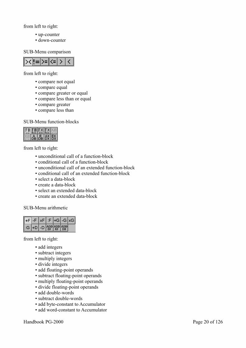
SUB-Menu arithmetic
from left to right:
• add integers• subtract integers• multiply integers• divide integers• add floating-point operands• subtract floating-point operands• multiply floating-point operands• divide floating-point operands• add double-words• subtract double-words• add byte-constant to Accumulator• add word-constant to Accumulator
Handbook PG-2000 Page 20 of 126
• add double-word-constant to Accumulator
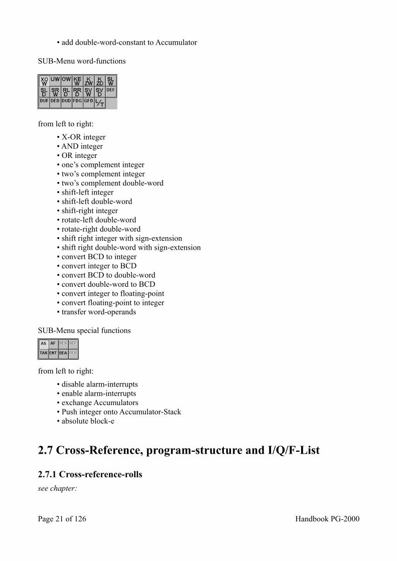
SUB-Menu word-functions
from left to right:
• X-OR integer• AND integer• OR integer• one’s complement integer• two’s complement integer• two’s complement double-word• shift-left integer• shift-left double-word• shift-right integer• rotate-left double-word• rotate-right double-word• shift right integer with sign-extension• shift right double-word with sign-extension• convert BCD to integer• convert integer to BCD• convert BCD to double-word• convert double-word to BCD• convert integer to floating-point• convert floating-point to integer• transfer word-operands
SUB-Menu special functions
from left to right:
• disable alarm-interrupts• enable alarm-interrupts• exchange Accumulators• Push integer onto Accumulator-Stack• absolute block-e
2.7 Cross-Reference, program-structure and I/Q/F-List
2.7.1 Cross-reference-rolls
see chapter:
Page 21 of 126 Handbook PG-2000
The XRF-List displays for one operand where else in the blocks this operand exists. The XRF-List refers always to all blocks in the actual block list. The XRF-list always refers to all components of the current block list.
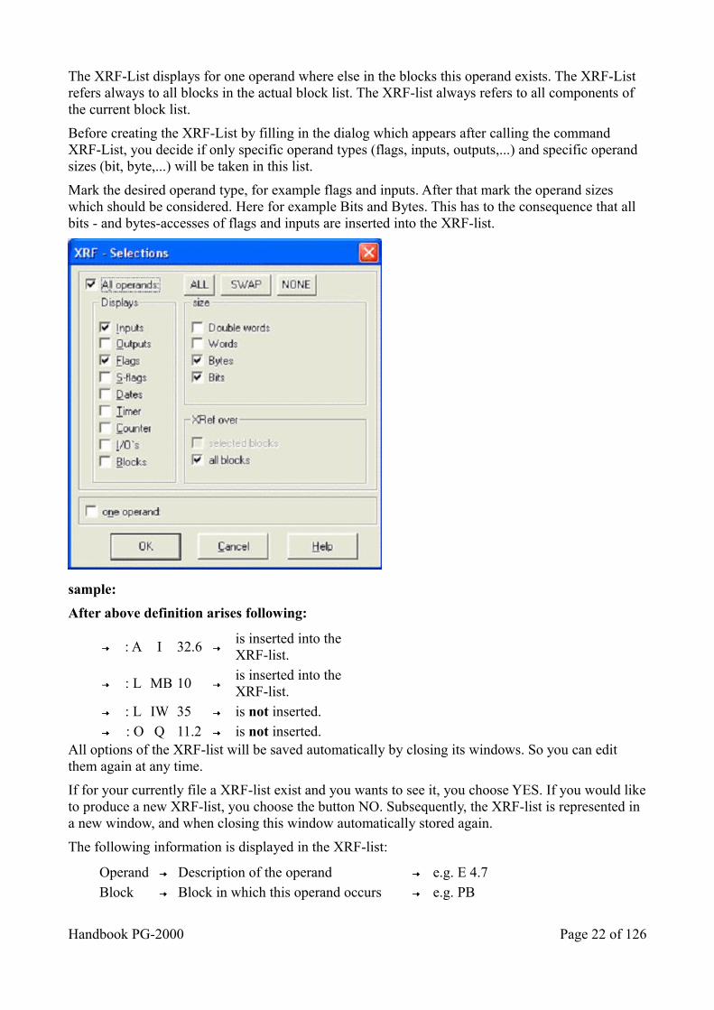
Before creating the XRF-List by filling in the dialog which appears after calling the command XRF-List, you decide if only specific operand types (flags, inputs, outputs,...) and specific operand sizes (bit, byte,...) will be taken in this list.
Mark the desired operand type, for example flags and inputs. After that mark the operand sizes which should be considered. Here for example Bits and Bytes. This has to the consequence that all bits - and bytes-accesses of flags and inputs are inserted into the XRF-list.
sample:
After above definition arises following:
: A I 32.6 is inserted into the XRF-list.
: L MB 10 is inserted into the XRF-list.
: L IW 35 is not inserted. : O Q 11.2 is not inserted. All options of the XRF-list will be saved automatically by closing its windows. So you can edit them again at any time.
If for your currently file a XRF-list exist and you wants to see it, you choose YES. If you would liketo produce a new XRF-list, you choose the button NO. Subsequently, the XRF-list is represented in a new window, and when closing this window automatically stored again.
The following information is displayed in the XRF-list:
Operand Description of the operand e.g. E 4.7 Block Block in which this operand occurs e.g. PB
Handbook PG-2000 Page 22 of 126
20
SegmentSegment in which this operand is saved
e.g. 26
Line Line in which this operand is written down
e.g. 12
Access Displays the access to the operand e.g. * The following are available:
- reading access - displayed by a blank.
- writing access - displayed by a ‘ * ’.
- parameter of a FB/FX-Call - displayed by a ‘ P ‘
After the access-mode, the program code line is displayed, in which the operand is used.
You move inside the XRF-list window by pressing the cursor keys or using the scroll-bars. If the cursor is on list line and you press <ENTER>, you change into the corresponding block window in that line, in which this operand occurs. Then the cursor is set on the corresponding line.
In consideration of the big amount of data that occur, always only a part of the data will be displayed. This depends of font's size. You can move in one part of the data from the begin to the end of the part. You move to the next part by using the key Page Up/Page Down. The end of the XRF-list is displayed specially.
You can jump among the different areas by pressing the first character:
I InputQ OutputF FlagD DataT TimeC CounterS S-FlagP Periphery
There is the command XRF in the menu XRF-list with functions for jumping into the correspondingblock window and for jumping to a specific area in the XRF-list.This menu contains also a function for sorting, which offers to get a XRF-list in variable order.
You can copy the context of the XRF-list into the clip board by calling the command Copy .
In the window ” Sort XRF ” you can choose on which way the XRF list should be sorted.
Page 23 of 126 Handbook PG-2000
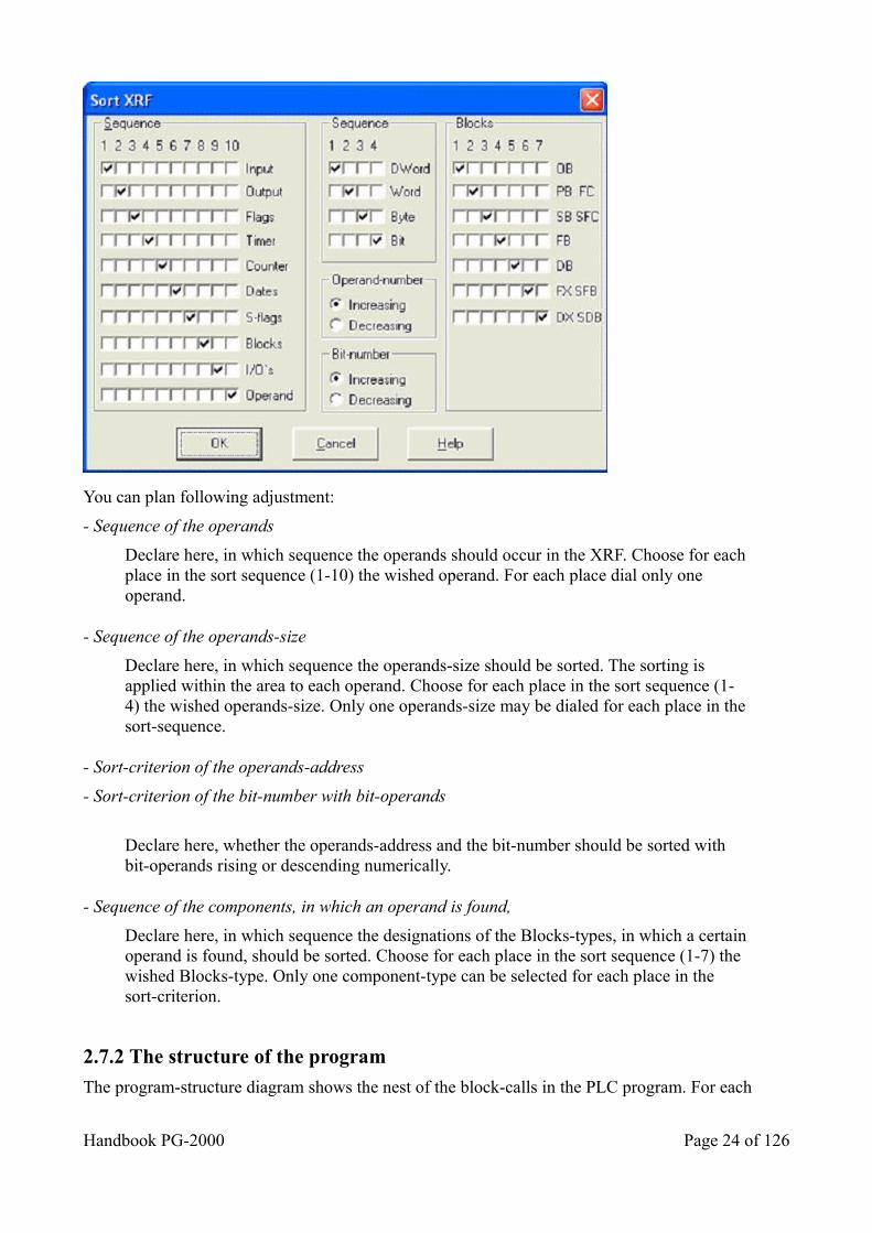
You can plan following adjustment:
- Sequence of the operands
Declare here, in which sequence the operands should occur in the XRF. Choose for eachplace in the sort sequence (1-10) the wished operand. For each place dial only one operand.
- Sequence of the operands-size
Declare here, in which sequence the operands-size should be sorted. The sorting is applied within the area to each operand. Choose for each place in the sort sequence (1-4) the wished operands-size. Only one operands-size may be dialed for each place in thesort-sequence.
- Sort-criterion of the operands-address
- Sort-criterion of the bit-number with bit-operands
Declare here, whether the operands-address and the bit-number should be sorted with bit-operands rising or descending numerically.
- Sequence of the components, in which an operand is found,
Declare here, in which sequence the designations of the Blocks-types, in which a certainoperand is found, should be sorted. Choose for each place in the sort sequence (1-7) the wished Blocks-type. Only one component-type can be selected for each place in the sort-criterion.
2.7.2 The structure of the program
The program-structure diagram shows the nest of the block-calls in the PLC program. For each
Handbook PG-2000 Page 24 of 126
marked block, all the blocks, which are called by it, are displayed.
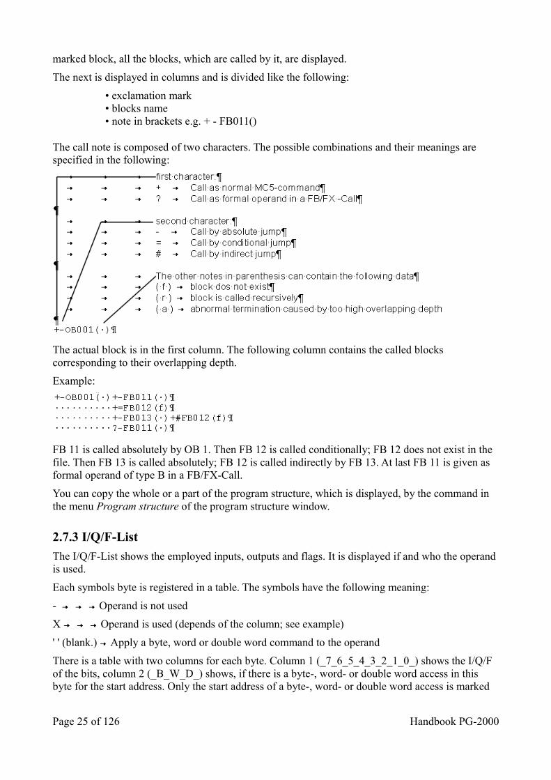
The next is displayed in columns and is divided like the following:
• exclamation mark• blocks name• note in brackets e.g. + - FB011()
The call note is composed of two characters. The possible combinations and their meanings are specified in the following:
The actual block is in the first column. The following column contains the called blocks corresponding to their overlapping depth.
Example:
FB 11 is called absolutely by OB 1. Then FB 12 is called conditionally; FB 12 does not exist in the file. Then FB 13 is called absolutely; FB 12 is called indirectly by FB 13. At last FB 11 is given as formal operand of type B in a FB/FX-Call.
You can copy the whole or a part of the program structure, which is displayed, by the command in the menu Program structure of the program structure window.
2.7.3 I/Q/F-List
The I/Q/F-List shows the employed inputs, outputs and flags. It is displayed if and who the operand is used.
Each symbols byte is registered in a table. The symbols have the following meaning:
- Operand is not used
X Operand is used (depends of the column; see example)
' ' (blank.) Apply a byte, word or double word command to the operand
There is a table with two columns for each byte. Column 1 (_7_6_5_4_3_2_1_0_) shows the I/Q/F of the bits, column 2 (_B_W_D_) shows, if there is a byte-, word- or double word access in this byte for the start address. Only the start address of a byte-, word- or double word access is marked
Page 25 of 126 Handbook PG-2000
with a X on the suitable place in the _B_W_D_ - column.
You have to look for X-marks in column 1, if you want to verify if one byte's single bits are used.
You have to look for X-marks in column 2 (X under B = byte access, X under W = word access, X under D = double word access), if you want to verify if one byte is the start address of byte-, word- or double word access.
There are two possibilities for checking a byte on being a part of a word or double word access:
1. Not every bit of the concerned bytes is used as bit-operand.2. Every bit of the concerned bytes is used as bit-operand.
In the first case you only have to verify if there is a blank filled in instead of "-" on a bit. In this case, the concerned byte is part of a word or double word access.In the second case you have to verify if the start address is given either for the concerned byte (byte access) or for the precede byte (word access) or for one of the three bytes before (double word access).
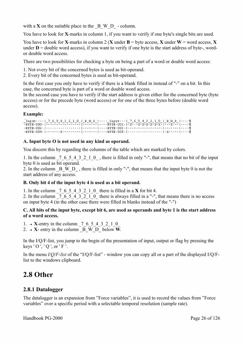
Example:
A. Input byte O is not used in any kind as operand.
You discern this by regarding the columns of the table which are marked by colors.
1. In the column _7_6_5_4_3_2_1_0_ , there is filled in only "-", that means that no bit of the input byte 0 is used as bit operand.2. In the column _B_W_D_ , there is filled in only "-", that means that the input byte 0 is not the start address of any access.
B. Only bit 4 of the input byte 4 is used as a bit operand.
1. In the column _7_6_5_4_3_2_1_0_ there is filled in a X for bit 4.2. In the column _7_6_5_4_3_2_1_0_ there is always filled in a "-", that means there is no access on input byte 4 (in the other case there were filled in blanks instead of the "-")
C. All bits of the input byte, except bit 6, are used as operands and byte 1 is the start address of a word access.
1. X-entry in the column _7_6_5_4_3_2_1_0_2. X- entry in the column _B_W_D_ below W.
In the I/Q/F-list, you jump to the begin of the presentation of input, output or flag by pressing the keys ' O ', ' Q ', or ' F ‘.
In the menu I/Q/F-list of the “I/Q/F-list” - window you can copy all or a part of the displayed I/Q/F-list to the windows clipboard.
2.8 Other
2.8.1 Datalogger
The datalogger is an expansion from ”Force variables”, it is used to record the values from ”Force variables” over a specific period with a selectable temporal resolution (sample rate).
Handbook PG-2000 Page 26 of 126
Enter in the window ”Forced variables” the data which should be observed. In the menu item ”Status” you can configurate the records. Following options are possible:
load datalogger only the configuration-data of the datalogger are loaded. If you would like to load the input variables in“Force variables”enter it over the option ”File/Open”.
save datalogger only the configuration data of the datenlogger will be stored.
configure datalogger
to call up the configuration-masks of the datalogger a description will follow.
start datalogger activate the datenlogger.
datalogger active shows if the datalogger is active at the next record. With this menu item the datalogger can switch into on or off
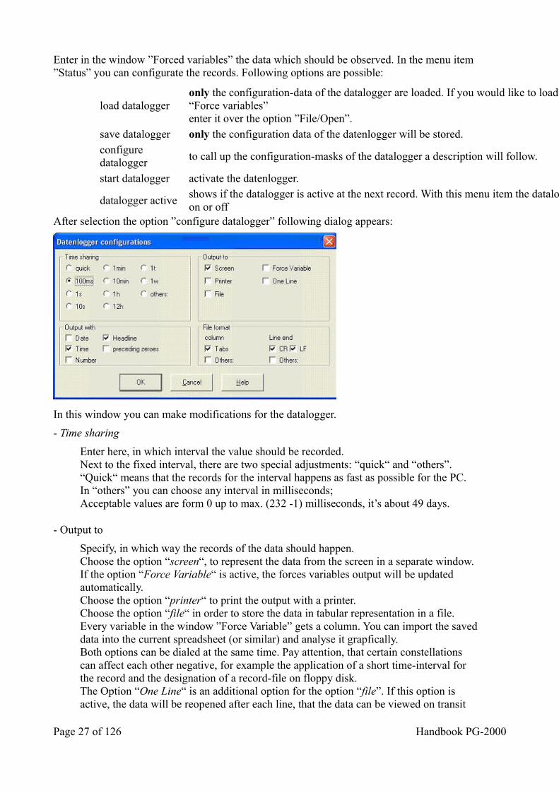
After selection the option ”configure datalogger” following dialog appears:
In this window you can make modifications for the datalogger.
- Time sharing
Enter here, in which interval the value should be recorded.Next to the fixed interval, there are two special adjustments: “quick“ and “others”.“Quick“ means that the records for the interval happens as fast as possible for the PC.In “others” you can choose any interval in milliseconds;Acceptable values are form 0 up to max. (232 -1) milliseconds, it’s about 49 days.
- Output to
Specify, in which way the records of the data should happen.Choose the option “screen“, to represent the data from the screen in a separate window.If the option “Force Variable“ is active, the forces variables output will be updated automatically.Choose the option “printer“ to print the output with a printer.Choose the option “file“ in order to store the data in tabular representation in a file. Every variable in the window ”Force Variable” gets a column. You can import the saveddata into the current spreadsheet (or similar) and analyse it grapfically.Both options can be dialed at the same time. Pay attention, that certain constellations can affect each other negative, for example the application of a short time-interval for the record and the designation of a record-file on floppy disk.The Option “One Line“ is an additional option for the option “file”. If this option is active, the data will be reopened after each line, that the data can be viewed on transit
Page 27 of 126 Handbook PG-2000
time.
- Output with
Specify, which supplementary files of the record should be contained in a data.
With the option “date“, you can save another column with the date of the record in the denoted file.
With the option “time“, you can save another column with the time of the record in the denoted file.
The two above named options are designated for long-lasting records.
With the option “number”, you can save another column with consecutively numbers for each line in the denoted file.
With the option “headline”, you can save headlines for the table-column in the denoted file. This option always can be dialed; the possibility of deactivating the table heading can be used to ease the imports of older programms.
With the option “preceding zeroes“ you can show zeros in front of the number. For example: 10 ? 0010
- File format
Here you can enter especial data format for saving the data.
- Column
With the option “tabs”, you can use the usual tabulator control character as table-separator.
With the option “others”, you can use your fixed symbol as table-separator.
- Line-end
The options “CR” (carriage return) and “LF” (line feed) is for the usual, common used line-end symbols.
With the option “others” you can use your own fixed symboles as line-end symbols.
The reference to the “Force Variable”-window above includes the “Force outputs”-window.The best result can be reached if the datalogger works out of the “Force Variable” window.
Handbook PG-2000 Page 28 of 126
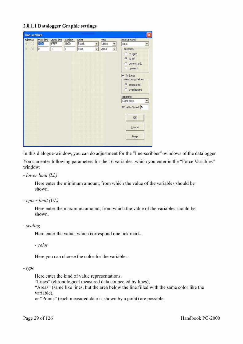
2.8.1.1 Datalogger Graphic settings
In this dialogue-window, you can do adjustment for the ”line-scribber”-windows of the datalogger.
You can enter following parameters for the 16 variables, which you enter in the “Force Variables”-window:
- lower limit (LL)
Here enter the minimum amount, from which the value of the variables should be shown.
- upper limit (UL)
Here enter the maximum amount, from which the value of the variables should be shown.
- scaling
Here enter the value, which correspond one tick mark.
- color
Here you can choose the color for the variables.
- type
Here enter the kind of value representations.“Lines” (chronological measured data connected by lines),“Areas” (same like lines, but the area below the line filled with the same color like the variable),or “Points” (each measured data is shown by a point) are possible.
Page 29 of 126 Handbook PG-2000
You can also enter following options:
- background
Enter the color of the background from the “line-scribber”-window.
- direction
Here enter one of the four possible directions: “downwards”, “upwards”, “to left” or “to right”.
- fix lines
If this option is active, separating lines will be marked between each period.
- measuring values
Here enter, if the gradient for more variables should drawn parallel or on top of each other.
- separator
Here enter the color of the separating lines for the periods.
- Pixel to Scroll
The number of pixels for the distance between each record.
2.8.1.2 Autostart Datalogger
The datalogger can be started automatically via command-line parameters. Therefor you need a BLT-file (what to record) and a DLG-file (how to record). Both files have the same name, except the flaring DLG/BLT. If you use S7 you have to switch the PG-2000 on S7 and choose the correct PLC. In the program-arguments will be entered “-DATALOG” together with a space and a file-name with BLT at the end.
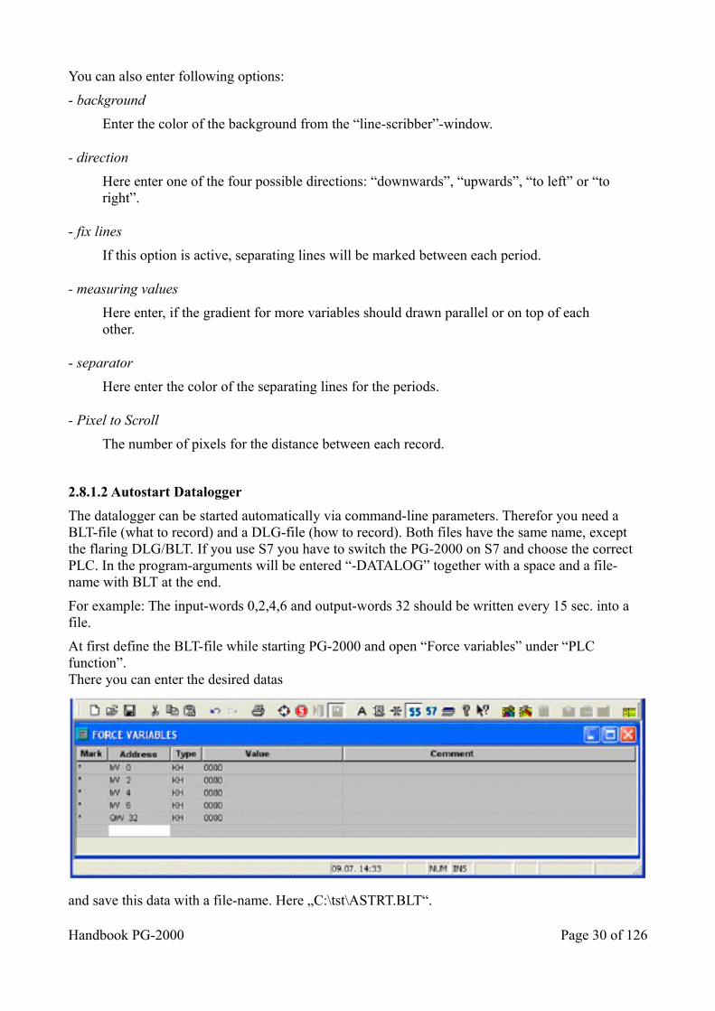
For example: The input-words 0,2,4,6 and output-words 32 should be written every 15 sec. into a file.
At first define the BLT-file while starting PG-2000 and open “Force variables” under “PLC function”.There you can enter the desired datas
and save this data with a file-name. Here „C:\tst\ASTRT.BLT“.
Handbook PG-2000 Page 30 of 126
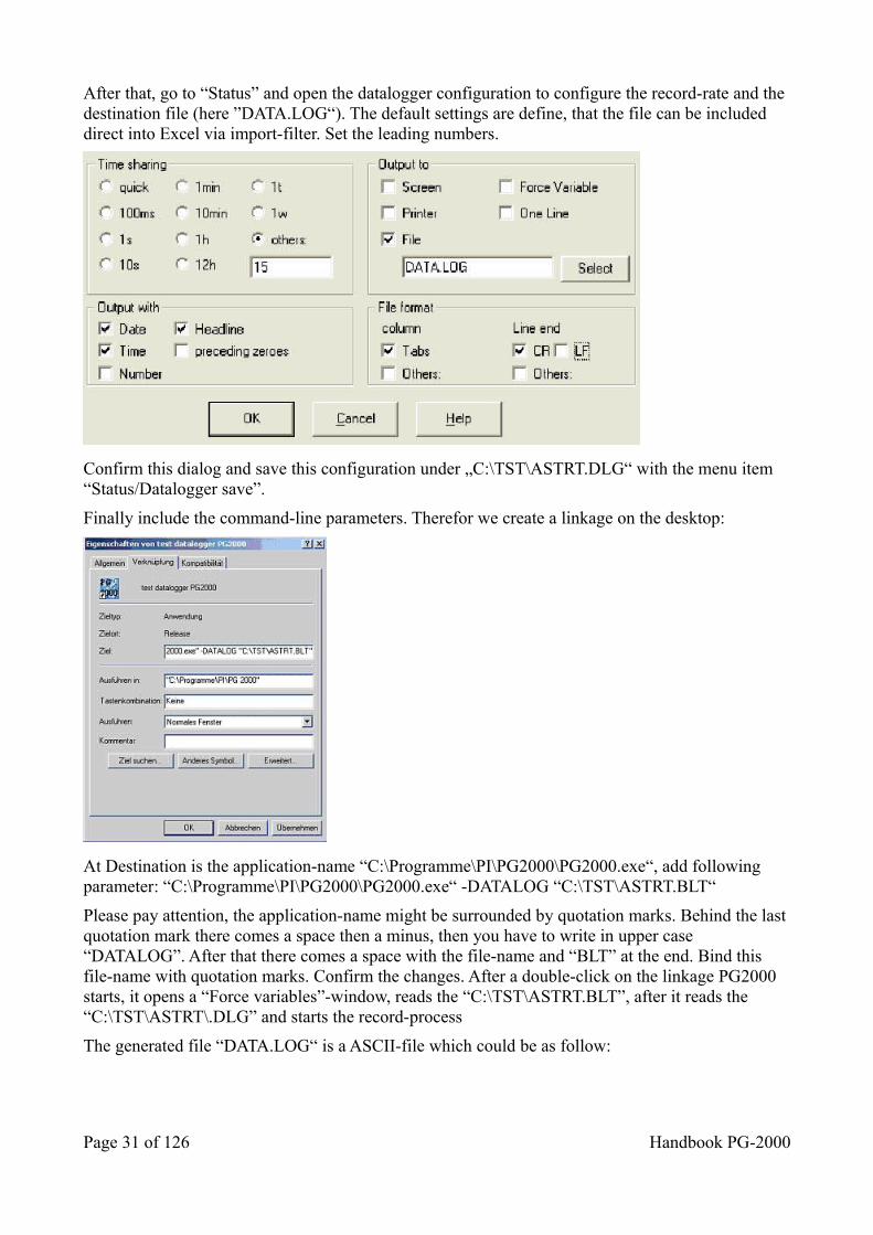
After that, go to “Status” and open the datalogger configuration to configure the record-rate and the destination file (here ”DATA.LOG“). The default settings are define, that the file can be included direct into Excel via import-filter. Set the leading numbers.
Confirm this dialog and save this configuration under „C:\TST\ASTRT.DLG“ with the menu item“Status/Datalogger save”.
Finally include the command-line parameters. Therefor we create a linkage on the desktop:
At Destination is the application-name “C:\Programme\PI\PG2000\PG2000.exe“, add following parameter: “C:\Programme\PI\PG2000\PG2000.exe“ -DATALOG “C:\TST\ASTRT.BLT“
Please pay attention, the application-name might be surrounded by quotation marks. Behind the last quotation mark there comes a space then a minus, then you have to write in upper case “DATALOG”. After that there comes a space with the file-name and “BLT” at the end. Bind this file-name with quotation marks. Confirm the changes. After a double-click on the linkage PG2000 starts, it opens a “Force variables”-window, reads the “C:\TST\ASTRT.BLT”, after it reads the “C:\TST\ASTRT\.DLG” and starts the record-process
The generated file “DATA.LOG“ is a ASCII-file which could be as follow:
Page 31 of 126 Handbook PG-2000
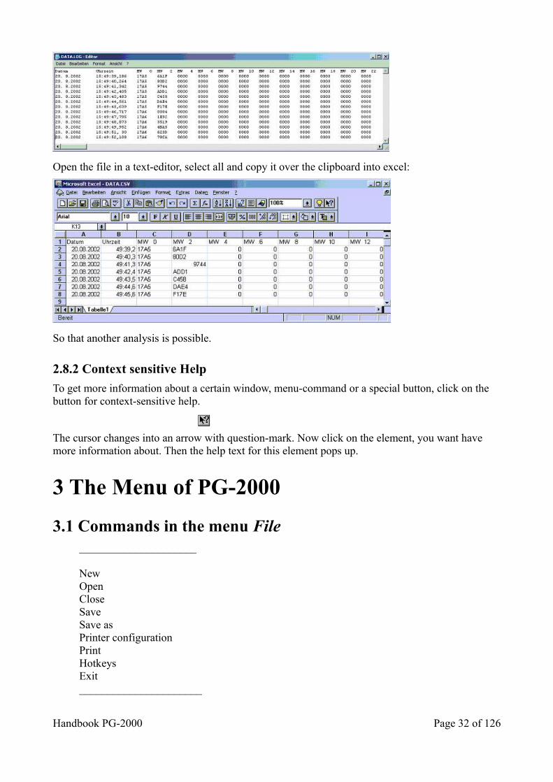
Open the file in a text-editor, select all and copy it over the clipboard into excel:
So that another analysis is possible.
2.8.2 Context sensitive Help
To get more information about a certain window, menu-command or a special button, click on the button for context-sensitive help.
The cursor changes into an arrow with question-mark. Now click on the element, you want have more information about. Then the help text for this element pops up.
3 The Menu of PG-2000
3.1 Commands in the menu File _____________________
NewOpenCloseSaveSave asPrinter configurationPrintHotkeysExit______________________
Handbook PG-2000 Page 32 of 126
3.1.1 Create a new file
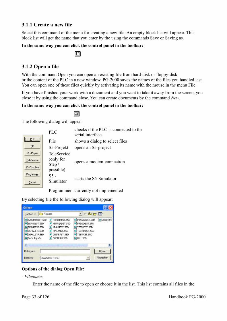
Select this command of the menu for creating a new file. An empty block list will appear. This block list will get the name that you enter by the using the commands Save or Saving as.
In the same way you can click the control panel in the toolbar:
3.1.2 Open a file
With the command Open you can open an existing file from hard-disk or floppy-diskor the content of the PLC in a new window. PG-2000 saves the names of the files you handled last.You can open one of these files quickly by activating its name with the mouse in the menu File.
If you have finished your work with a document and you want to take it away from the screen, you close it by using the command close. You can create documents by the command New.
In the same way you can click the control panel in the toolbar:
The following dialog will appear
PLC
checks if the PLC is connected to the serial interface
File shows a dialog to select files S5-Projekt opens an S5-project TeleService (only for Step7 possible)
opens a modem-connection
S5 - Simulator
starts the S5-Simulator
Programmer currently not implemented
By selecting file the following dialog will appear:
Options of the dialog Open File:
- Filename:
Enter the name of the file to open or choose it in the list. This list contains all files in the
Page 33 of 126 Handbook PG-2000
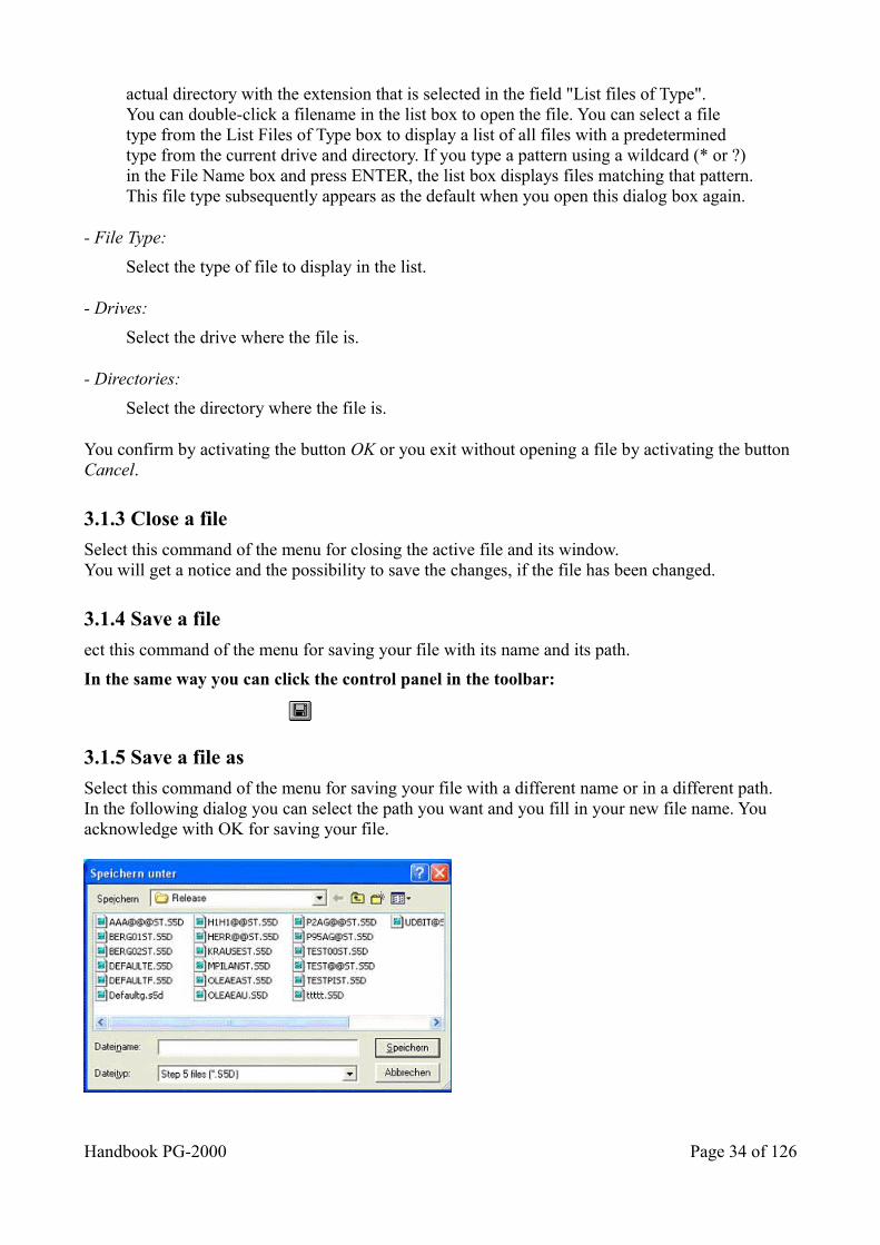
actual directory with the extension that is selected in the field "List files of Type".You can double-click a filename in the list box to open the file. You can select a file type from the List Files of Type box to display a list of all files with a predetermined type from the current drive and directory. If you type a pattern using a wildcard (* or ?) in the File Name box and press ENTER, the list box displays files matching that pattern.This file type subsequently appears as the default when you open this dialog box again.
- File Type:
Select the type of file to display in the list.
- Drives:
Select the drive where the file is.
- Directories:
Select the directory where the file is.
You confirm by activating the button OK or you exit without opening a file by activating the button Cancel.
3.1.3 Close a file
Select this command of the menu for closing the active file and its window.You will get a notice and the possibility to save the changes, if the file has been changed.
3.1.4 Save a file
ect this command of the menu for saving your file with its name and its path.
In the same way you can click the control panel in the toolbar:
3.1.5 Save a file as
Select this command of the menu for saving your file with a different name or in a different path.In the following dialog you can select the path you want and you fill in your new file name. You acknowledge with OK for saving your file.
Handbook PG-2000 Page 34 of 126
You can transfer your file completely into the PLC in the same way.Select the button PLC in the following dialog.
Options of the dialog Save As:
- Filename:
Enter the name of the file to save or choose it in the list. This list contains all files in the actual directory with the extension that is selected in the field "List files of Type".You can double-click a filename in the list box to open the file. You can select a file type from the List Files of Type box to display a list of all files with a predetermined type from the current drive and directory. If you type a pattern using a wildcard (* or ?) in the File Name box and press ENTER, the list box displays files matching that pattern. This file type subsequently appears as the default when you open this dialog box again.
- File Type:
Select the type of file to display in the list.
- Drives:
Select the drive where to save the file.
- Directories:
Select the directory where to save the file.
You confirm by activating the button OK or you exit without saving this file by activating the buttonCancel.
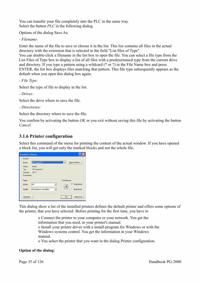
3.1.6 Printer configuration
Select this command of the menu for printing the content of the actual window. If you have opened a block list, you will get only the marked blocks and not the whole file.
This dialog show a list of the installed printers defines the default printer and offers some options ofthe printer, that you have selected. Before printing for the first time, you have to
o Connect the printer to your computer or your network. You get the information that you need, in your printer's manual.o Install your printer driver with a install-program for Windows or with the Windows systems control. You get the information in your Windows manual.o You select the printer that you want in the dialog Printer configuration.
Option of the dialog:
Page 35 of 126 Handbook PG-2000
- Standard printer:
Show the name of the standard printer and the connection.
- Special printer:
Choose your printer. PG-2000 shows the printers that are installed in Windows. You get information about the installation of printers in your Windows manual.
- Format
Choose your format for the print.
- Paper - size and feeding
Enter the size of the paper and the paper feeding
- Options
Controls the print options of the printer that is selected in the list. The available options depend of the installed printer driver. You get information about the selected printer by clicking the Options-button and then the Help-button.
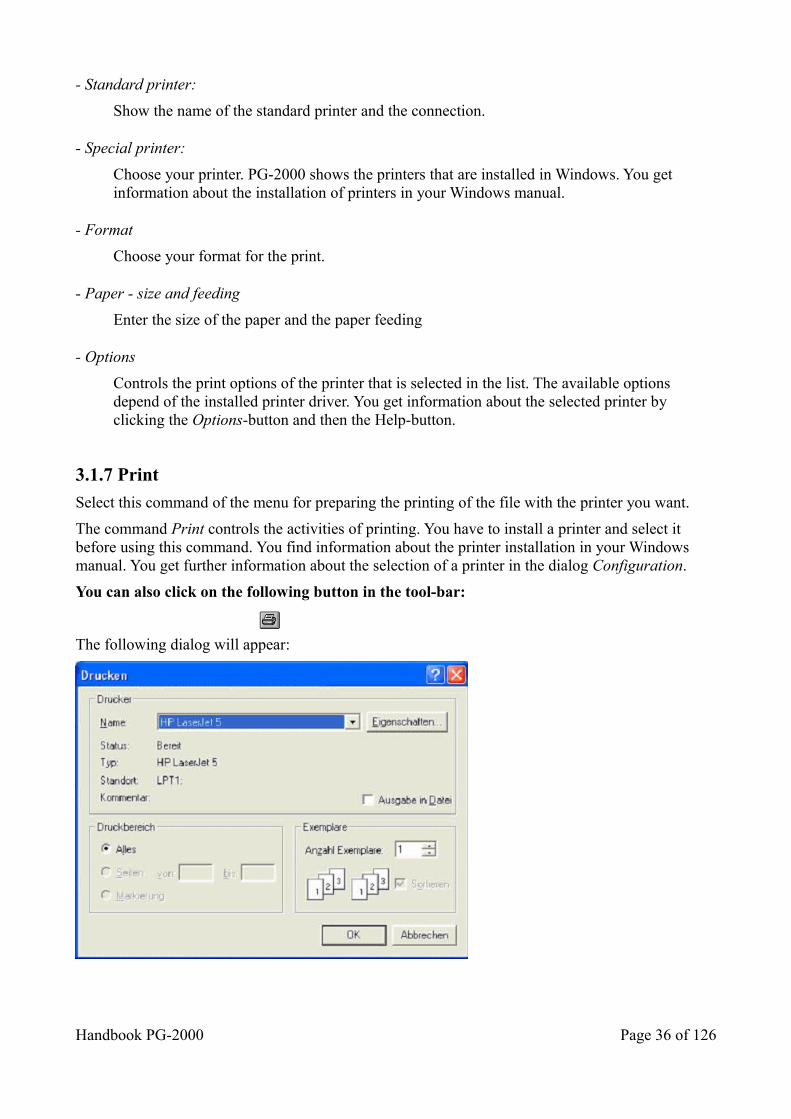
3.1.7 Print
Select this command of the menu for preparing the printing of the file with the printer you want.
The command Print controls the activities of printing. You have to install a printer and select it before using this command. You find information about the printer installation in your Windows manual. You get further information about the selection of a printer in the dialog Configuration.
You can also click on the following button in the tool-bar:
The following dialog will appear:
Handbook PG-2000 Page 36 of 126
Options in the dialog:
- Printer
Show the name of the actual printer and the connection.
- All
Prints the whole document.
- Pages
Prints the page that you enter.
- Copies
Enter the number of copies that you want to print.
- Assort copies
Assorts the page to exemplars if you print several exemplars of a file.
- Quality
You choose the resolution of the print.
3.1.8 Hotkeys
Here you get the last ten files, which were opened by you. For opening one of these files you choose one by mouse or you use the hot-keys: 1, 2, 3, ... 9
3.1.9 Exit the program
Select this command of the menu for to exit the program PG-2000.
3.2 Commands in the menu Window ______________________
CascadeTile horizontalArrange symbolsHotkeysMore Windows______________________
3.2.1 Cascade
This command displays all windows in a cascade.
3.2.2 Tile horizontal
This command displays all windows side by side.
Page 37 of 126 Handbook PG-2000
3.2.3 Arrange symbols
If you have minimized your documents into symbols, you can arrange them in lines with this command.
3.2.4 Hotkeys
Here is the list of the ten current windows which have been opened by you. You select one of these windows by using the mouse in the menu or by pressing the hot-keys: 1, 2, 3, … 9
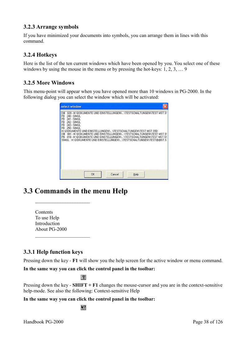
3.2.5 More Windows
This menu-point will appear when you have opened more than 10 windows in PG-2000. In the following dialog you can select the window which will be activated:
3.3 Commands in the menu Help ______________________
ContentsTo use HelpIntroductionAbout PG-2000______________________
3.3.1 Help function keys
Pressing down the key - F1 will show you the help screen for the active window or menu command.
In the same way you can click the control panel in the toolbar:
Pressing down the key - SHIFT + F1 changes the mouse-cursor and you are in the context-sensitivehelp-mode. See also the following: Context-sensitive Help
In the same way you can click the control panel in the toolbar:
Handbook PG-2000 Page 38 of 126
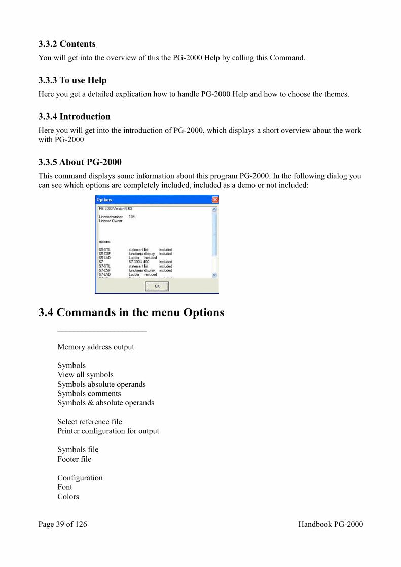
3.3.2 Contents
You will get into the overview of this the PG-2000 Help by calling this Command.
3.3.3 To use Help
Here you get a detailed explication how to handle PG-2000 Help and how to choose the themes.
3.3.4 Introduction
Here you will get into the introduction of PG-2000, which displays a short overview about the workwith PG-2000
3.3.5 About PG-2000
This command displays some information about this program PG-2000. In the following dialog youcan see which options are completely included, included as a demo or not included:
3.4 Commands in the menu Options ______________________
Memory address output
SymbolsView all symbolsSymbols absolute operandsSymbols commentsSymbols & absolute operands
Select reference filePrinter configuration for output
Symbols fileFooter file
ConfigurationFontColors
Page 39 of 126 Handbook PG-2000
Address of the S-flag fieldSEQ->STLInterfaces______________________
3.4.1 Memory address output
A dialog will be displayed after activating this command, in which you can indicate if and how to display the memory addresses of each STL-Command.There are the following possibilities:
• none The memory addresses of the commands are not displayed in the STL.
• hexadecimal in words
The first column of the STL contains the memory addresses of the following command in words hexadecimal.
• hexadecimal in bytesThe first column of the STL contains the memory addresses of the following command in bytes hexadecimal.
• decimal in words The first column of the STL contains the memory addresses of the following command in words decimal.
• decimal in bytes The first column of the STL contains the memory addresses of the following command in bytes decimal.
3.4.2 Commands in Symbols file...
_________________
NewOpenHotkeys_________________
3.4.2.1 Symbols file ... New
Select this command for creating a new symbol file. An empty symbol editor window will be displayed at first. The file gets the filename that you enter in the dialog which follows the commands save or save as.
3.4.2.2 Symbols file... Open
Choose in the following dialog the file, which contains the desired symbol definitions.
Call the command View all symbols in the menu Options for changing some symbols or for appending some new symbols.
You create a new symbols file by calling the command New in the menu Options-Symbols file.
Save your symbol file by using the commands save or save as in the menu File.
3.4.2.3 Symbols file..., Hotkeys
Here is the list of the ten last symbol files which has been opened by you. You select one of these file to open by using the mouse in the menu or by pressing the hot-keys: 1, 2, 3, … 9The first file in this list always is regarded as valid and is handled as already chosen.
Handbook PG-2000 Page 40 of 126
3.4.3 Functions for Symbols file
3.4.3.1 Symbols
Select this command for changing between ”Symbol active” and ”Symbol inactive”. Symbol can beused in the STL-editor, in the CSF(S5) / FBD(S7) - editor and in the LAD-editor.All defined Symbol Operands are substituted by the corresponding symbol. In the editor you can use the Symbol Operands (for example QW 15) directly or the symbol for it (for example MOTOR 2).If Symbol is active, its command in the menu is marked.If you have activated Symbol, the symbol definitions are printed after the printed program.
3.4.3.2 View all symbols files
This command calls the symbol editor. This editor displays all symbols of the selected symbol file.You can change, delete or create any symbols. Save your changed symbol file by using the command save or save as in the menu File.
3.4.3.3 View absolute operands
This command displays the allocation of a symbolic operand. Select this command (if the cursor is placed on a program line which contains a symbolic operand) for displaying the absolute operand, the symbolic operand and the corresponding symbols comment in a dialog.
3.4.3.4 Symbols comment
Select this command for displaying the statement comment instead of the symbols comment. This function is only active for the program lines in which a symbol operand is associated. There is no possibility to edit the symbol comment.
If the symbol comment is active, the command in the menu is marked.
3.4.3.5 Symbols & absolute operands
Select this command for displaying the absolute and the symbol operand. This command is possiblein all program lines which contain a symbol operand association. The absolute operand can be edited.
If the Symbol and the Absolute operand are active, this command in the menu is marked.
3.4.4 Footer file...
3.4.5 _________________
NewOpenHotkeys_________________
The footer offers you the possibility to print specific data of the project or the person. You can enter here the project number, name of the employee etc.On each print the selected footer is printer on the end of each page. You choose in the dialog print
Page 41 of 126 Handbook PG-2000
format if you want to print a footer or not. You call this dialog by calling the command Printer configuration for output in the menu Options. If you once have defined a footer, the first footer in the file list in the menu Options/Footer file is the default footer.
The footer editor displays the footer in the same disposition like it will be printed. You can choose between the standard formats of Siemens (80 char or 132 char large) with defined sections. You change among the several sections by pressing TAB or SHIFT + TAB. Inside a section, you move with the cursor keys and you edit like usually in Windows.If you have selected the 132 char large footer, it cannot be displayed in the whole size. You change between the left and the right part by activating the buttons Part 1... and Part 2... .
You save the changed file by activating the button Save with the original name or by activating the button Save as with a different name.
3.4.5.1 Footer file ... New
Select this command in the menu for creating a footer file. You have to indicate the desired foots width in the following dialog. The empty footer dialog is displayed after acknowledging the choice. You save your entries by pressing the buttons save or saving as in the footer dialog.
3.4.5.2 Footer file ... Open
Select this command for opening an existing footer file. The footer dialog depends of the entered format of the selected file (80 or 132 characters width).You choose file in the dialog File Open, which contains the desired footer definitions.The command New in the menu Options-Footer File creates a new symbols file. Save your edited footer file by using the buttons save or saving as in the footer dialog.
3.4.5.3 Footer file... Hotkeys
Here you see the list of the last ten footer files, which have been opened by you. For opening one ofthese windows you may use the command of the menu or use the hot-keys: 1, 2, 3, … 10The first file in the list is regarded as actual valid footer file and will be used for the following print activities.
3.4.6 Use reference file
With this menu item you can enable or disable the usage of a reference file.To disable the checkbox must be checked.
The alternate option is to click the following symbol:
3.4.7 Select a reference file ...
If you transfer the data and MC5-blocks into the PLC, the corresponding Reference Blocks (DV) and the Documentation Blocks (DC) will not be transferred.For editing the blocks in the PLC you have the possibility to declare the corresponding S5D-file by using this command.
You can open the corresponding file in the following dialog. You select the reference-file for the contents in the PLC, and now you have all reference data and documentation data while you edit theblocks on the PLC.
Handbook PG-2000 Page 42 of 126
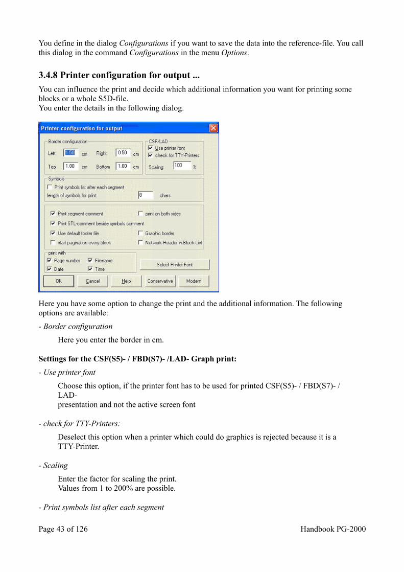
You define in the dialog Configurations if you want to save the data into the reference-file. You call this dialog in the command Configurations in the menu Options.
3.4.8 Printer configuration for output ...
You can influence the print and decide which additional information you want for printing some blocks or a whole S5D-file.You enter the details in the following dialog.
Here you have some option to change the print and the additional information. The following options are available:
- Border configuration
Here you enter the border in cm.
Settings for the CSF(S5)- / FBD(S7)- /LAD- Graph print:
- Use printer font
Choose this option, if the printer font has to be used for printed CSF(S5)- / FBD(S7)- / LAD-presentation and not the active screen font
- check for TTY-Printers:
Deselect this option when a printer which could do graphics is rejected because it is aTTY-Printer.
- Scaling
Enter the factor for scaling the print.Values from 1 to 200% are possible.
- Print symbols list after each segment
Page 43 of 126 Handbook PG-2000
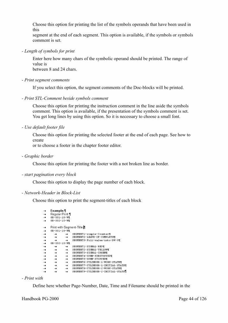
Choose this option for printing the list of the symbols operands that have been used in thissegment at the end of each segment. This option is available, if the symbols or symbolscomment is set.
- Length of symbols for print
Enter here how many chars of the symbolic operand should be printed. The range of value isbetween 8 and 24 chars.
- Print segment comments
If you select this option, the segment comments of the Doc-blocks will be printed.
- Print STL-Comment beside symbols comment
Choose this option for printing the instruction comment in the line aside the symbols comment. This option is available, if the presentation of the symbols comment is set. You get long lines by using this option. So it is necessary to choose a small font.
- Use default footer file
Choose this option for printing the selected footer at the end of each page. See how to createor to choose a footer in the chapter footer editor.
- Graphic border
Choose this option for printing the footer with a not broken line as border.
- start pagination every block
Choose this option to display the page number of each block.
- Network-Header in Block-List
Choose this option to print the segment-titles of each block
- Print with
Define here whether Page-Number, Date, Time and Filename should be printed in the
Handbook PG-2000 Page 44 of 126
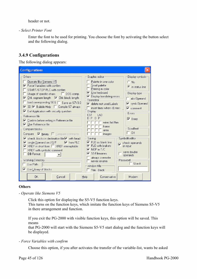
header or not.
- Select Printer Font
Enter the font to be used for printing. You choose the font by activating the button selectand the following dialog.
3.4.9 Configurations
The following dialog appears:
Others
- Operate like Siemens V5
Click this option for displaying the S5-V5 function keys.This turns on the function keys, which imitate the function keys of Siemens S5-V5in there arrangement and function.
If you exit the PG-2000 with visible function keys, this option will be saved. This meansthat PG-2000 will start with the Siemens S5-V5 start dialog and the function keys willbe displayed.
- Force Variables with confirm
Choose this option, if you after activates the transfer of the variable-list, wants be asked
Page 45 of 126 Handbook PG-2000
again whether the data should really be transferred to the PLC.
- START/STOP PLC with confirm
Choose this option, when you want with each attempt the PLC starting or stop, toreceive an explicit message. With out this option, the PLC is immediately started or stopped.
- Usage of specific chars
Select this option for using specific and national characters as valid input characters.
These chars can not be displayed properly in the orginal Siemens PG´s
- DOS comp.
The specific chars are coded differently under Windows as in DOS.Turn this option on, when you want to use DOS-compatible chars.
- Check segment length
Choose this option in order to test the segment-length for 255 words and, to receive amistake-news with demand.
- Check block length
It is testing when saving, whether the block becomes not too big. If the block shouldbecome too big, so the user is pointed out of this. With voting out, not SIEMENScompatible files, which work correctly in the PLC, can be generated. They could notread with SIEMENS programming software.
- Load corresponding SEQ
When active, the corresponding Symbolic-File will be loaded as well when opening anS5D-File
- Save as S7V3.0
In Version 3.0 of the S7 the root-file has had a different format. Therefore this optionexists. But today this option is not needed anymore.
- 3D-effect
Choose this option, about to turn on 3D-effect.
- Bubble-Help
Choose this option in order to switch on the Bubble-Help. If you let a certain time standthe mouse-pointer over a button, a help is shown under the button.
- Compile S7 Always
The complete project will be reorganized (time-consuming).
Handbook PG-2000 Page 46 of 126
- Exit Application with security question
When this option is active a Message box will appear before exiting the program.
Reference file
- Confirm before writing Reference file
If this adjustment is turned on, you must confirm each writing process into the selected reference file, presupposed application of the put in reference file is active.You select the reference file under OPTIONS, SELECT REFERENCE FILES.
- Use Reference file
Is this adjustment is choose, a connection exist to a defaulted reference file. Under OPTIONS, SELECT REFERENCE FILES can be selected this file. The selectedreference-file may not be opened with the access on the PLC then. If you open then the PLC you get the comments and the symbolic to see, because the connection with the reference file. With each storage process, now stored in the PLC and in the selected reference file, with retrieval or without, dependence from adjustment inCONFIGURATION, REFERENCE FIL, CONFIRM BEFORE WRITING IN REFERENCE FILE.
If you would not like to work with a reference file, so you don’t choose this adjustment.
Compare blocks
- Compare binary
Choose this option, to compare only the pure STEP 5 Code.
- Compare comments
If you select this option, it compares also different commentaries.
- check blocks in destination file
The blocks in the destination file will be checked
- with head
When this option is active the block header will be checked, too and displayedcorrespondingly when the content differs. (default value is off)
- Single Operand on I/Q/F
Choose this option in order only to show the operand in the XRF-list, in the first lines. Ifthere are several lines with the same operand, so the operand is represented only in thefirst line.
- XREF in short form
Choose this option, to show more than a position with the XRF-list within on line.
- XREF interruptible
If the XRF-list should be generated in the background, however, still to execute other
Page 47 of 126 Handbook PG-2000
works in the foreground, it (like for example texts prints or produces) can be admitted the message handling by adjustment of this point. The disadvantage is that the XRF-list over many blocks are quite long.
- XREF with symbolic comment
The symbolic comment of the operant will be displayed, too.
- DB-Format
If the reference-data is not present in the S5D-file or in the PLC then this will be thedefault displaying format
Working Directory
- Use Path
That here put in file-path is defaulted with all file accesses in PG-2000.
- Use Library of blocks
Choose this option, if you want to work with the blocks from the blocks library. If you now generate a new block that exists in the block library, you get a block with the parameter of the block in the library.
The block library consists of 6 files in the PI/ PG-2000 directory:
- DEFAULTE.S5D/S7P for adjustment in English language- DEFAULTF.S5D/S7P for adjustment in French language- DEFAULTD.S5D/S7P for adjustment in German language
If you create a new block into one of the above 3 file, the automatic parameter becomes effective for this block, first after finish PG-2000 and started again. This adjustment is absolutely necessary for S7.
Graphic editor
Options of the CSF(S5)- / FBD(S7)- / LAD- graphic editor.
- Palette in one color
Select this option for getting a white/gray colored presentation of the toolbar.This option is recommended for systems with reduced color display,like LCD-displays for example.
- Small palette
Select this option for getting a smaller palette. This option is recommended for thestandard VGA resolution for economizing place on the screen. This option is only in theone color mode available because of it’s visibility.
- Printings in color
Select this option for printing the CSF(S5)- / FBD(S7)- / LAD- print in colors if you have a color printer. There is no conversion in black/white output.
Handbook PG-2000 Page 48 of 126
- Use keyboard
A courser, which can be controlled with the keyboard, is displayed. The functions from the menu refer to this cursor.
- Display translating errors
With a mistake in the transposition, to the user is pointed out.
Texteditor
- delete not used Labels
If a label is never used, then it will be deleted. This label will be erased permanently.
- insert lines when <Enter>
When active, a new line after the current line will be inserted when pressing enter.
Display
These options define the displaying of the symbol’s background and the symbol’s frames and the way to draw the wire connections.The options are separate for the displaying of CSF(S5) / FBD(S7) and LAD and for the displaying on the screen (D= Display) and on the printer (P=Printer).
- wires fat/thin
The wire connections will be displayed large and plastically if this option is on. The status blocks will be displayed in colors which correspond to their actual logic mode.The wire connection will be displayed as small lines if this option is off. The actual logic mode will be displayed by the line. A line means logic 1 and a broken line means logic 0.
- frame
The frame of the symbols is drawn in the selected color if this option is on. No frame is drawn if this option is off.
- area
The background of the symbols is displayed in the selected color if this option is on. If this option is off no background is displayed.
- images
If this option is turned on, so a picture is showed within the symbol.If this option is turned off, a text is showed within the symbol.
The print job runs faster if the last three options are off
Saving
- FLO as blank line
Between connections in a network there will be generated a blank line.
Page 49 of 126 Handbook PG-2000
- FLO with brackets
The first bracket about the first connection in a network can be left out without loss of the logical function. These networks are not representable in the SIEMENS original PG in CSF(S5) / FBD(S7).
- NOP in T/C
Without parameter Input/output in times and counters, Siemens concurring NOP 0 lines are generated. PG-2000 doesn’t require these lines to recognition of a Timer/Counter. If the NOPs are missing however, the Siemens-PG can represent this network not in CSF(S5) / FBD(S7) or LAD.
- S5-Filenames
The Siemes convention is now used with the file-names. Name cut off on 6 signs,lacking signs with ”@” replenished and in the end ”ST.S5D” appended.
Example:
T ...................T@@@@@ST.S5DTEST.S5D..... TEST@@ST.S5DTESTST........ TESTSTST.S5Dtest00st.S5D.. TEST00ST.S5D
- always overwrite
When transferring a block from A to B and the block to transfer already exists a Message box appears whether the existing block should be overwritten or not. When this option is active, the Message box won’t appear and the existing block will always be overwritten.
- never rename
When transferring a block from A to B always a Message box appears where you can rename the block for the destination. When this option is active, this dialog will notappear.
Window title
- 'file - Block'
When active, the filename will be displayed before the block name in the window title when opening a block.
Display symbols
(right mouse button)You define where to display the information about the selected symbolic operands by calling this command. The following settings are available:
- No
No information about the symbolic operand is displayed.
- in status line
Handbook PG-2000 Page 50 of 126
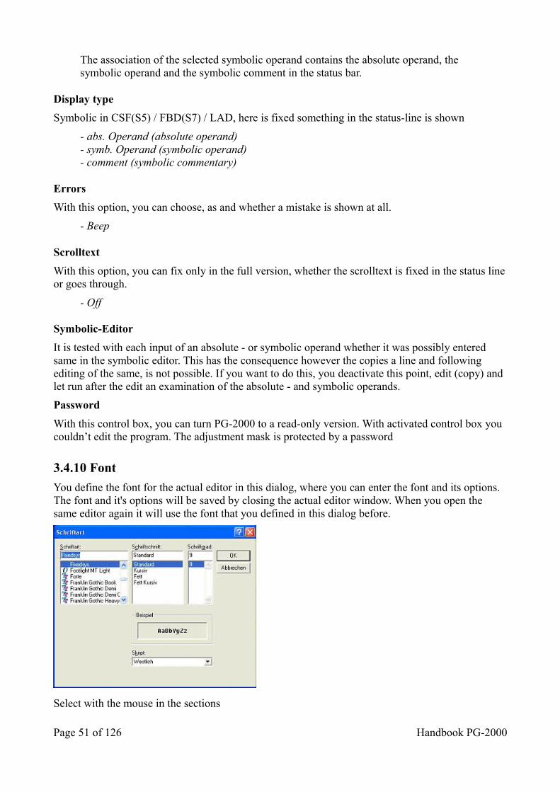
The association of the selected symbolic operand contains the absolute operand, the symbolic operand and the symbolic comment in the status bar.
Display type
Symbolic in CSF(S5) / FBD(S7) / LAD, here is fixed something in the status-line is shown
- abs. Operand (absolute operand)- symb. Operand (symbolic operand)- comment (symbolic commentary)
Errors
With this option, you can choose, as and whether a mistake is shown at all.
- Beep
Scrolltext
With this option, you can fix only in the full version, whether the scrolltext is fixed in the status lineor goes through.
- Off
Symbolic-Editor
It is tested with each input of an absolute - or symbolic operand whether it was possibly entered same in the symbolic editor. This has the consequence however the copies a line and following editing of the same, is not possible. If you want to do this, you deactivate this point, edit (copy) and let run after the edit an examination of the absolute - and symbolic operands.
Password
With this control box, you can turn PG-2000 to a read-only version. With activated control box you couldn’t edit the program. The adjustment mask is protected by a password
3.4.10 Font
You define the font for the actual editor in this dialog, where you can enter the font and its options. The font and it's options will be saved by closing the actual editor window. When you open the same editor again it will use the font that you defined in this dialog before.
Select with the mouse in the sections
Page 51 of 126 Handbook PG-2000
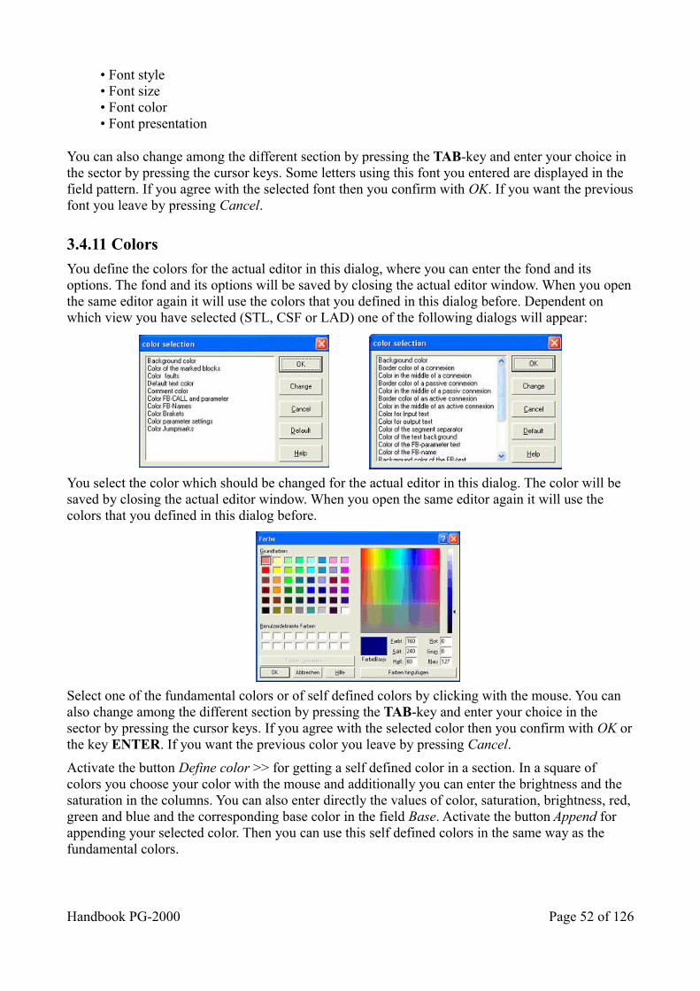
• Font style• Font size• Font color• Font presentation
You can also change among the different section by pressing the TAB-key and enter your choice in the sector by pressing the cursor keys. Some letters using this font you entered are displayed in the field pattern. If you agree with the selected font then you confirm with OK. If you want the previousfont you leave by pressing Cancel.
3.4.11 Colors
You define the colors for the actual editor in this dialog, where you can enter the fond and its options. The fond and its options will be saved by closing the actual editor window. When you openthe same editor again it will use the colors that you defined in this dialog before. Dependent on which view you have selected (STL, CSF or LAD) one of the following dialogs will appear:
You select the color which should be changed for the actual editor in this dialog. The color will be saved by closing the actual editor window. When you open the same editor again it will use the colors that you defined in this dialog before.
Select one of the fundamental colors or of self defined colors by clicking with the mouse. You can also change among the different section by pressing the TAB-key and enter your choice in the sector by pressing the cursor keys. If you agree with the selected color then you confirm with OK orthe key ENTER. If you want the previous color you leave by pressing Cancel.
Activate the button Define color >> for getting a self defined color in a section. In a square of colors you choose your color with the mouse and additionally you can enter the brightness and the saturation in the columns. You can also enter directly the values of color, saturation, brightness, red,green and blue and the corresponding base color in the field Base. Activate the button Append for appending your selected color. Then you can use this self defined colors in the same way as the fundamental colors.
Handbook PG-2000 Page 52 of 126
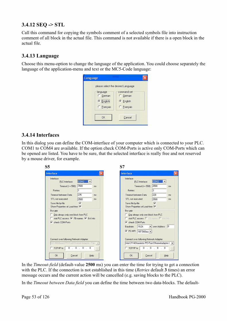
3.4.12 SEQ -> STL
Call this command for copying the symbols comment of a selected symbols file into instruction comment of all block in the actual file. This command is not available if there is a open block in the actual file.
3.4.13 Language
Choose this menu-option to change the language of the application. You could choose separately thelanguage of the application-menu and text or the MC5-Code language:
3.4.14 Interfaces
In this dialog you can define the COM-interface of your computer which is connected to your PLC. COM1 to COM4 are available. If the option check COM-Ports is active only COM-Ports which canbe opened are listed. You have to be sure, that the selected interface is really free and not reserved by a mouse driver, for example.
S5 S7
In the Timeout-field (default-value 2500 ms) you can enter the time for trying to get a connection with the PLC. If the connection is not established in this time (Retries default 3 times) an error message occurs and the current action will be cancelled (e.g. saving blocks to the PLC).
In the Timeout between Data field you can define the time between two data-blocks. The default-
Page 53 of 126 Handbook PG-2000
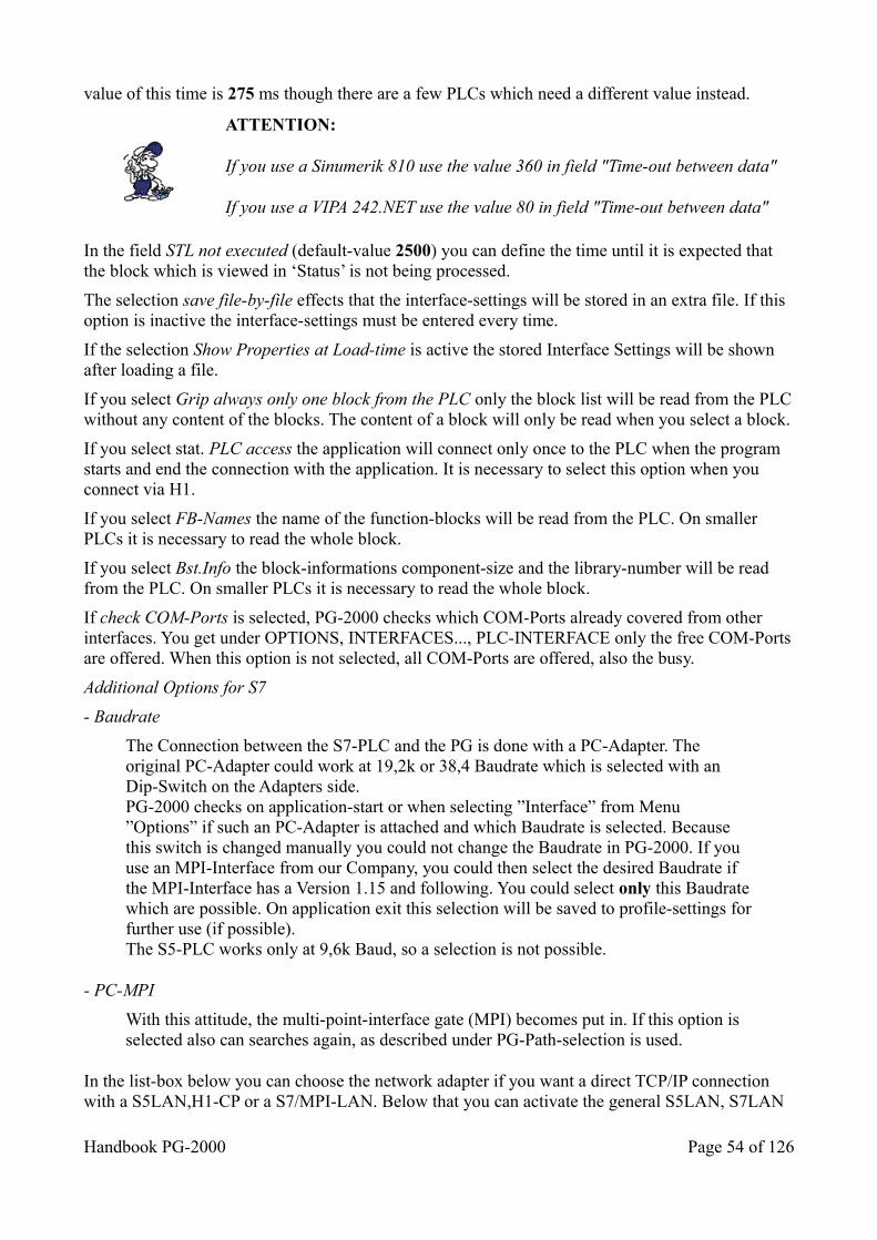
value of this time is 275 ms though there are a few PLCs which need a different value instead.
ATTENTION:
If you use a Sinumerik 810 use the value 360 in field "Time-out between data"
If you use a VIPA 242.NET use the value 80 in field "Time-out between data"
In the field STL not executed (default-value 2500) you can define the time until it is expected that the block which is viewed in ‘Status’ is not being processed.
The selection save file-by-file effects that the interface-settings will be stored in an extra file. If this option is inactive the interface-settings must be entered every time.
If the selection Show Properties at Load-time is active the stored Interface Settings will be shown after loading a file.
If you select Grip always only one block from the PLC only the block list will be read from the PLCwithout any content of the blocks. The content of a block will only be read when you select a block.
If you select stat. PLC access the application will connect only once to the PLC when the program starts and end the connection with the application. It is necessary to select this option when you connect via H1.
If you select FB-Names the name of the function-blocks will be read from the PLC. On smaller PLCs it is necessary to read the whole block.
If you select Bst.Info the block-informations component-size and the library-number will be read from the PLC. On smaller PLCs it is necessary to read the whole block.
If check COM-Ports is selected, PG-2000 checks which COM-Ports already covered from other interfaces. You get under OPTIONS, INTERFACES..., PLC-INTERFACE only the free COM-Portsare offered. When this option is not selected, all COM-Ports are offered, also the busy.
Additional Options for S7
- Baudrate
The Connection between the S7-PLC and the PG is done with a PC-Adapter. The original PC-Adapter could work at 19,2k or 38,4 Baudrate which is selected with an Dip-Switch on the Adapters side.PG-2000 checks on application-start or when selecting ”Interface” from Menu ”Options” if such an PC-Adapter is attached and which Baudrate is selected. Because this switch is changed manually you could not change the Baudrate in PG-2000. If you use an MPI-Interface from our Company, you could then select the desired Baudrate if the MPI-Interface has a Version 1.15 and following. You could select only this Baudratewhich are possible. On application exit this selection will be saved to profile-settings forfurther use (if possible).The S5-PLC works only at 9,6k Baud, so a selection is not possible.
- PC-MPI
With this attitude, the multi-point-interface gate (MPI) becomes put in. If this option is selected also can searches again, as described under PG-Path-selection is used.
In the list-box below you can choose the network adapter if you want a direct TCP/IP connection with a S5LAN,H1-CP or a S7/MPI-LAN. Below that you can activate the general S5LAN, S7LAN
Handbook PG-2000 Page 54 of 126
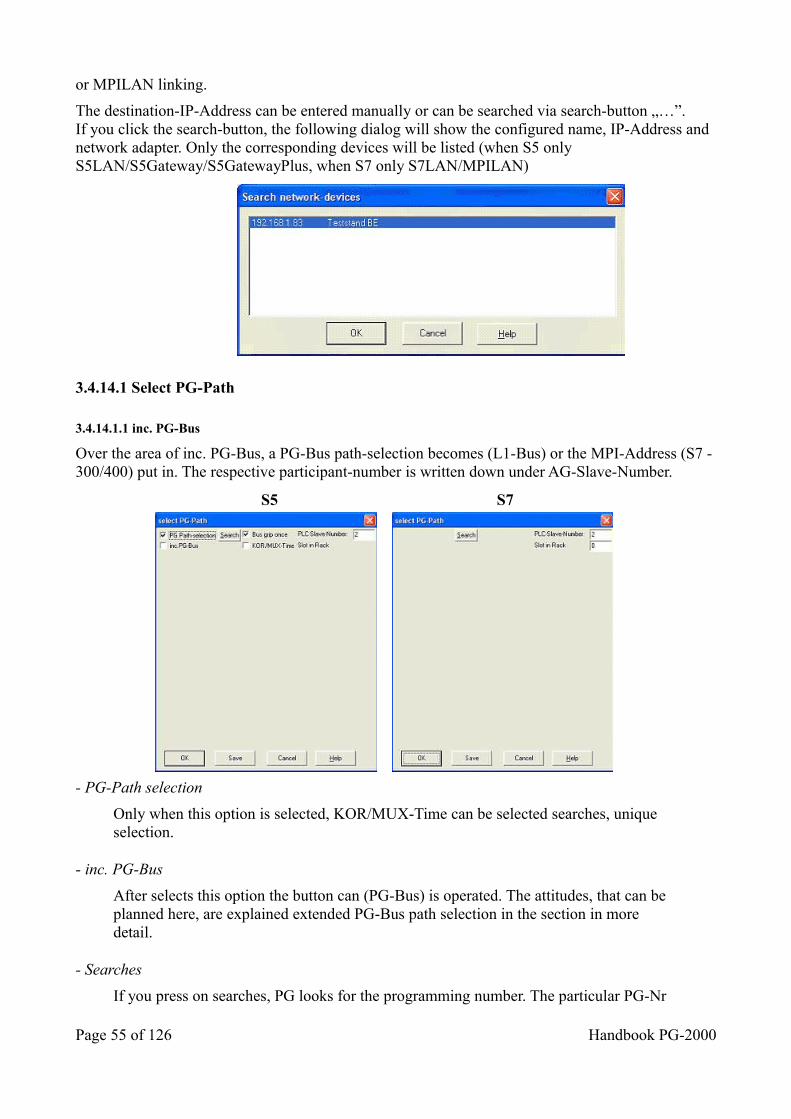
or MPILAN linking.
The destination-IP-Address can be entered manually or can be searched via search-button „…”.If you click the search-button, the following dialog will show the configured name, IP-Address and network adapter. Only the corresponding devices will be listed (when S5 only S5LAN/S5Gateway/S5GatewayPlus, when S7 only S7LAN/MPILAN)
3.4.14.1 Select PG-Path
3.4.14.1.1 inc. PG-Bus
Over the area of inc. PG-Bus, a PG-Bus path-selection becomes (L1-Bus) or the MPI-Address (S7 -300/400) put in. The respective participant-number is written down under AG-Slave-Number.
S5 S7
- PG-Path selection
Only when this option is selected, KOR/MUX-Time can be selected searches, unique selection.
- inc. PG-Bus
After selects this option the button can (PG-Bus) is operated. The attitudes, that can be planned here, are explained extended PG-Bus path selection in the section in more detail.
- Searches
If you press on searches, PG looks for the programming number. The particular PG-Nr
Page 55 of 126 Handbook PG-2000
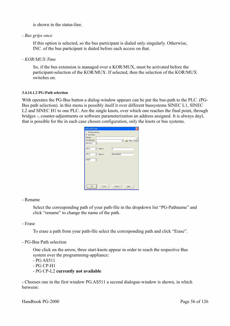
is shown in the status-line.
- Bus grips once
If this option is selected, so the bus participant is dialed only singularly. Otherwise, INC. of the bus participant is dialed before each access on that.
- KOR/MUX-Time
So, if the bus extension is managed over a KOR/MUX, must be activated before the participant-selection of the KOR/MUX. If selected, then the selection of the KOR/MUXswitches on.
3.4.14.1.2 PG-Path selection
With operates the PG-Bus button a dialog-window appears can be put the bus-path to the PLC. (PG-Bus path selection). in this menu is possibly itself it over different bussystems SINEC L1, SINEC L2 and SINEC H1 to one PLC. Are the single knots, over which one reaches the final point, throughbridges -, counter-adjustments or software parameterization an address assigned. It is always dayl, that is possible for the in each case chosen configuration, only the knots or bus systems.
- Rename
Select the corresponding path of your path-file in the dropdown list “PG-Pathname” andclick “rename” to change the name of the path.
- Erase
To erase a path from your path-file select the corresponding path and click “Erase”.
- PG-Bus Path selection
One click on the arrow, three start-knots appear in order to reach the respective Bus system over the programming-appliance:- PG AS511- PG CP-H1- PG CP-L2 currently not available
- Chooses one in the first window PG.AS511 a second dialogue-window is shown, in which between:
Handbook PG-2000 Page 56 of 126
- KOR/MUX- CP-H1- CP-L2- CP-L1 can be chosen.
- Chooses one in the first window PG CP-H1 a second dialogue-window is shown, in which between:
- PG CP-H1- CP-H1 can be chosen.
- Chooses one in the first Window. PG CP-L2 a second dialogue-window is shown, in which between:
- PG CP-L2- CP-L2 can be chosen.
- Chooses one in the second window SINEC H1, three more windows appear:
- Ethernet-Address (must be inputted as hexadecimal)- Password (to the protection before forbidden access)- Windows to the selection between PG CP-H1, CP-H1
- Chooses one in the second window KOR/MUX, two windows appear:
- Address (here is inputted the respective address)- Windows to the selection betweenENDP for final point (end-knots)CP-H1, CP-L1, CP-L2, in order to change to another Bus system,
!!! The PG CP-H1, PG CP-L2 chose is possibly not yet !!!
Example:
From PG (AS511) over CP-L1 to CP-L1 address 0021A00602C to the PLC
3.4.15 Address of the S-Flags in the Memory of the PLC
Here you enter the address of the S-flag area in the memory of the PLC in hexadecimal numbers.
This option is necessary for function "Status Block" and "Force Variable" with the PLCs S5-PLC135U/PLC155U.
If this option is not entered correctly, the displayed values of the S-flag instructions in "Status Block", e.g. in the instruction like "U S 1000.0", and for access to the S-flag-area in "Force Variable", e.g. with operands like "SW 10", do not match with their originally values in the PLC.
You get this value in your system manual (in the chapter "Memory structure" or some like this). Also if the PLC works in a 20-bit-address area, the address must be declared as 16-bit-base address;if the S-flag area is e.g. at EA000, you have to enter the value EA00.
Values for different PLCs:
• PLC 115U ( CPU 945 ) .....E000• PLC 135U ( CPU 928B )... E400• PLC 155U ( CPU 948 )..... EA00
Page 57 of 126 Handbook PG-2000
If 0 is entered the corresponding value for the PLC will be selected automatically.
3.5 Commands in the menu PLC-Functions ______________________
Start PLCStop PLCCompress PLCDelete PLCForce variablesStart status blockStop status blockOutput PLC infoOutput memory configurationOutput memory contentsISTACKBSTACK______________________
3.5.1 Start PLC
This command starts the PLC and the program starts running.
In the same way you can click the control panel in the toolbar:
3.5.2 Stop PLC
This command stops the PLC and the program stops running.
In the same way you can click the control panel in the toolbar:
3.5.3 Compress PLC
When you delete a block in the PLC, the block is not deleted in the memory but marked as deleted. The memory is fragmented by doing this. So you have to call the command compress for getting a cohered free memory again. All blocks, which are not marked as deleted, are contracted by this command and the one piece of free memory rests, which contains the free part of the memory and the deleted blocks.
Handbook PG-2000 Page 58 of 126

Tip:While the PLC is running in cycle only one block per cycle pass is shifted. Depending on the cycle timethis can take very long (e.g. 270 blocks by 1 second cycle time are approximately 4,5 minutes). According to possibility stop the PLC for a moment or enter a BEA in the beginning of OB1. Thereby the cycle-time will be reduced and the PLC will be faster. However the machine will be changed, so this step should be well-considered or only used in the manual operating mode without PLC.
3.5.4 Delete PLC
This command deletes all block in the PLC. The marked blocks are deleted and removed. This command is equivalent to the command Factory Reset of the PLC. The PLC will be in the STOP-mode and only the internal system blocks and the DB 1 will rest, corresponding to the Factory Resetof the PLC.
3.5.5 Output PLC-Info
Here you get information about the status and the content of the memory in the PLC.
3.5.6 Output memory configuration
You get information of the memory configuration in your PLC by calling this command.These are the following:
- The start address and the end address of the available memory.- The start address and the end address of the memory used by the program.- The size of the free memory.
3.5.7 Output memory contents
The content of the whole PLC's memory is displayed by calling this command.The value of each memory address from 0 hex to maximal FFF hex (depends of the PLC type) is displayed in a list box.
Page 59 of 126 Handbook PG-2000
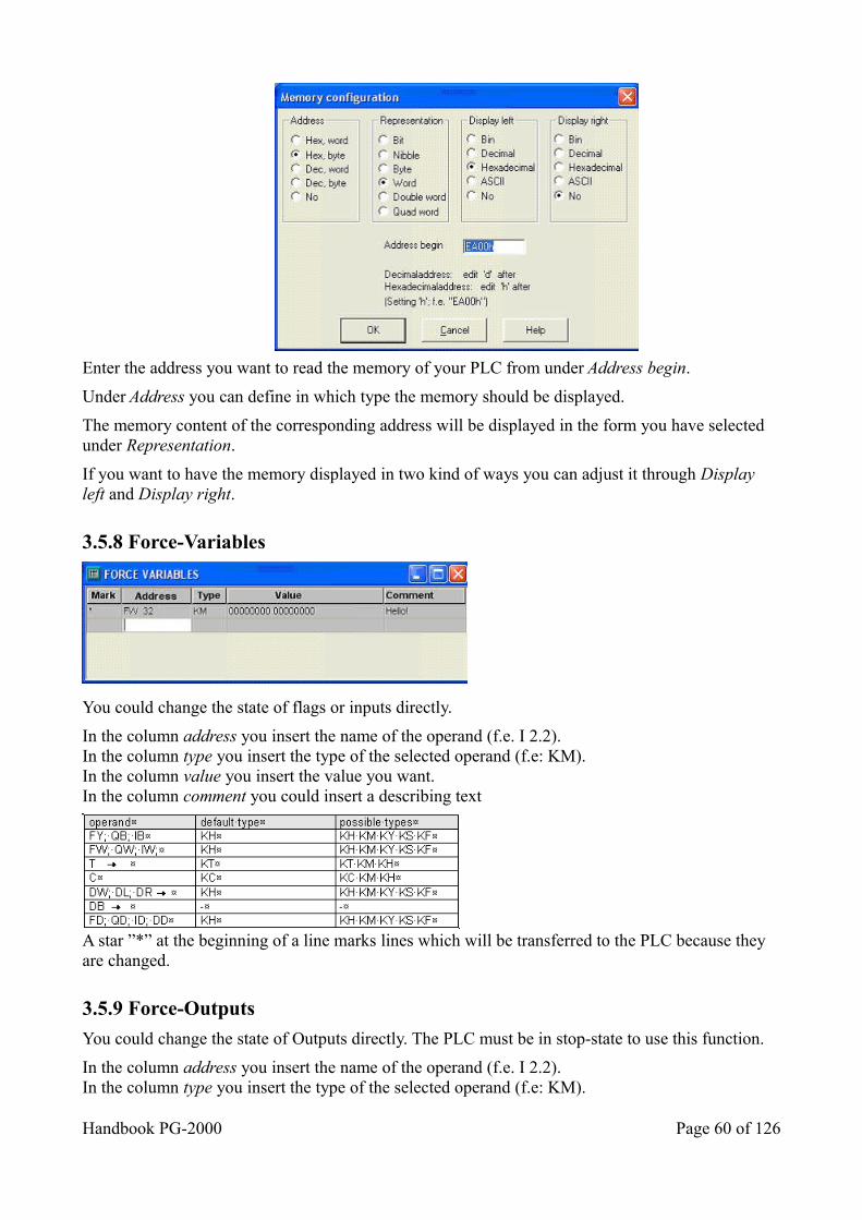
Enter the address you want to read the memory of your PLC from under Address begin.
Under Address you can define in which type the memory should be displayed.
The memory content of the corresponding address will be displayed in the form you have selected under Representation.
If you want to have the memory displayed in two kind of ways you can adjust it through Display left and Display right.
3.5.8 Force-Variables
You could change the state of flags or inputs directly.
In the column address you insert the name of the operand (f.e. I 2.2).In the column type you insert the type of the selected operand (f.e: KM).In the column value you insert the value you want.In the column comment you could insert a describing text
A star ”*” at the beginning of a line marks lines which will be transferred to the PLC because they are changed.
3.5.9 Force-Outputs
You could change the state of Outputs directly. The PLC must be in stop-state to use this function.
In the column address you insert the name of the operand (f.e. I 2.2).In the column type you insert the type of the selected operand (f.e: KM).
Handbook PG-2000 Page 60 of 126
In the column value you insert the value you want.In the column comment you could insert a describing text
Only Bytes and Words possible!
3.5.10 Start status block
The command start status block starts the presentation of the actual window's status. This command is only available, if
a) the PLC is already opened by you andb) you are actually in a window of a block that exists on the PLC
The command status block is available for block in MC5-code only, that means not for data blocks for example. If this command has been selected, the following information will be displayed behindeach Step5 command-line.
1) DBADR = Address of the actual data block. This address is not assigned to any block or 0 2) DB-Nr = Number of Data-block actually selected 3) VKE = Actual logic result at this point.
4)Status/Accu1
= Content of accu 1 or status (depends of the instruction)
5) Acc2 = Content of accu 2. 6) Stytus = the set bits are displayed here after the respective instruction
7) SAC =Step5 Address counter. The addresses of the respective program code are displayed in the PLC.
The values above will be read in the PLC and displayed after each PLC-cycle. This will happen until you stop the mode Status Block by calling the command Status blocks stop
3.5.11 Stop status block
This command stops displaying the status of the actual block window. After this command, the status information will not be read and displayed any longer.
3.5.12 ISTACK
This command displays the Interrupt Stack in your PLC. The Interrupt Stack contains data which contain some information of the reason why the PLC has stopped the program. You get further explication of the specifications by clicking the Help-button in the dialog ISTACK
3.5.12.1 Istack (PLC 95U/100U/115U)
This dialog displays the Interrupt-Stack in your PLC. The Interrupt-Stack contains the information of the cause of interrupt and why the program has been stopped. The following information is savedin this stack:
Symbol operand
signification
Page 61 of 126 Handbook PG-2000
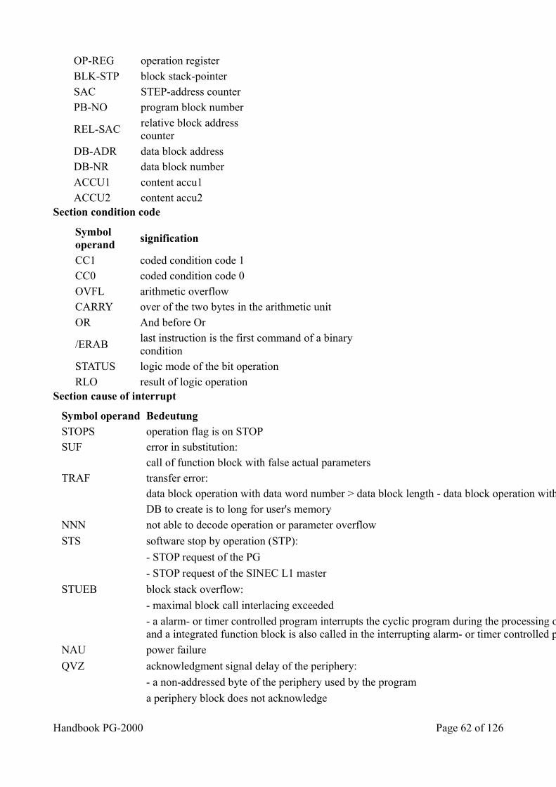
OP-REG operation register BLK-STP block stack-pointer SAC STEP-address counter PB-NO program block number
REL-SAC relative block address counter
DB-ADR data block address DB-NR data block number ACCU1 content accu1 ACCU2 content accu2 Section condition code
Symbol operand
signification
CC1 coded condition code 1 CC0 coded condition code 0 OVFL arithmetic overflow CARRY over of the two bytes in the arithmetic unit OR And before Or
/ERAB last instruction is the first command of a binarycondition
STATUS logic mode of the bit operation RLO result of logic operation Section cause of interrupt
Symbol operand Bedeutung STOPS operation flag is on STOP SUF error in substitution: call of function block with false actual parameters TRAF transfer error: data block operation with data word number > data block length - data block operation without opened DB DB to create is to long for user's memory
NNN not able to decode operation or parameter overflow
STS software stop by operation (STP):
- STOP request of the PG
- STOP request of the SINEC L1 master
STUEB block stack overflow:
- maximal block call interlacing exceeded
- a alarm- or timer controlled program interrupts the cyclic program during the processing of an integrated function blockand a integrated function block is also called in the interrupting alarm- or timer controlled program.
NAU power failure
QVZ acknowledgment signal delay of the periphery:
- a non-addressed byte of the periphery used by the program
a periphery block does not acknowledge
Handbook PG-2000 Page 62 of 126
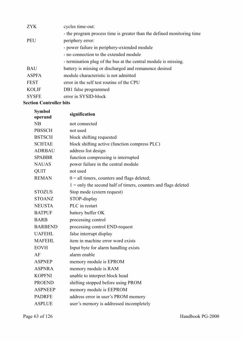
ZYK cycles time-out:
- the program process time is greater than the defined monitoring time
PEU periphery error:
- power failure in periphery-extended module
- no connection to the extended module
- termination plug of the bus at the central module is missing.
BAU battery is missing or discharged and remanence desired
ASPFA module characteristic is not admitted
FEST error in the self test routine of the CPU
KOLIF DB1 false programmed
SYSFE error in SYSID-block Section Controller bits
Symbol operand
signification
NB not connected PBSSCH not used BSTSCH block shifting requested SCHTAE block shifting active (function compress PLC) ADRBAU address list design SPABBR function compressing is interrupted NAUAS power failure in the central module
QUIT not used
REMAN 0 = all timers, counters and flags deleted;
1 = only the second half of timers, counters and flags deleted
STOZUS Stop mode (extern request)
STOANZ STOP-display
NEUSTA PLC in restart
BATPUF battery buffer OK
BARB processing control
BARBEND processing control END-request
UAFEHL false interrupt display
MAFEHL item in machine error word exists
EOVH Input byte for alarm handling exists
AF alarm enable
ASPNEP memory module is EPROM
ASPNRA memory module is RAM
KOPFNI unable to interpret block head
PROEND shifting stopped before using PROM
ASPNEEP memory module is EEPROM
PADRFE address error in user’s PROM memory
ASPLUE user’s memory is addressed incompletely
Page 63 of 126 Handbook PG-2000
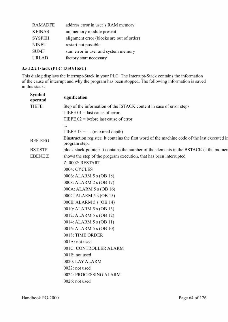
RAMADFE address error in user’s RAM memory
KEINAS no memory module present
SYSFEH alignment error (blocks are out of order)
NINEU restart not possible
SUMF sum error in user and system memory
URLAD factory start necessary
3.5.12.2 Istack (PLC 135U/155U)
This dialog displays the Interrupt-Stack in your PLC. The Interrupt-Stack contains the information of the cause of interrupt and why the program has been stopped. The following information is savedin this stack:
Symbol operand
signification
TIEFE Step of the information of the ISTACK content in case of error steps TIEFE 01 = last cause of error, TIEFE 02 = before last cause of error ... TIEFE 13 = .... (maximal depth)
BEF-REG Binstruction register: It contains the first word of the machine code of the last executed instruction of the interrupted program step.
BST-STP block stack-pointer: It contains the number of the elements in the BSTACK at the moment of the interrupted program step.
EBENE Z shows the step of the program execution, that has been interrupted
Z: 0002: RESTART
0004: CYCLES
0006: ALARM 5 s (OB 18)
0008: ALARM 2 s (OB 17)
000A: ALARM 5 s (OB 16)
000C: ALARM 5 s (OB 15)
000E: ALARM 5 s (OB 14)
0010: ALARM 5 s (OB 13)
0012: ALARM 5 s (OB 12)
0014: ALARM 5 s (OB 11)
0016: ALARM 5 s (OB 10)
0018: TIME ORDER
001A: not used
001C: CONTROLLER ALARM
001E: not used
0020: LAY ALARM
0022: not used
0024: PROCESSING ALARM
0026: not used
Handbook PG-2000 Page 64 of 126
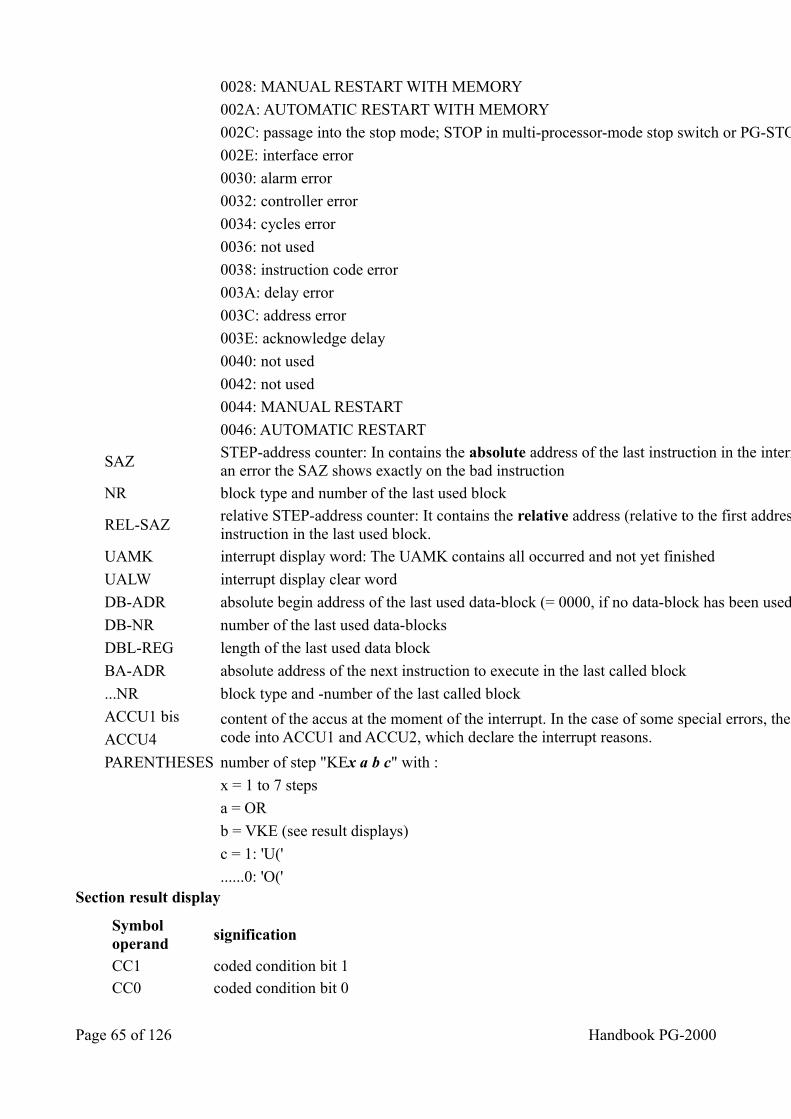
0028: MANUAL RESTART WITH MEMORY
002A: AUTOMATIC RESTART WITH MEMORY
002C: passage into the stop mode; STOP in multi-processor-mode stop switch or PG-STOP
002E: interface error
0030: alarm error
0032: controller error
0034: cycles error
0036: not used
0038: instruction code error
003A: delay error
003C: address error
003E: acknowledge delay
0040: not used
0042: not used
0044: MANUAL RESTART
0046: AUTOMATIC RESTART
SAZ STEP-address counter: In contains the absolute address of the last instruction in the interrupted program step. In the case of an error the SAZ shows exactly on the bad instruction
NR block type and number of the last used block
REL-SAZ relative STEP-address counter: It contains the relative address (relative to the first address of the block) of the last instruction in the last used block.
UAMK interrupt display word: The UAMK contains all occurred and not yet finished
UALW interrupt display clear word
DB-ADR absolute begin address of the last used data-block (= 0000, if no data-block has been used)
DB-NR number of the last used data-blocks
DBL-REG length of the last used data block
BA-ADR absolute address of the next instruction to execute in the last called block
...NR block type and -number of the last called block
ACCU1 bis content of the accus at the moment of the interrupt. In the case of some special errors, the system program saves an error code into ACCU1 and ACCU2, which declare the interrupt reasons. ACCU4
PARENTHESES number of step "KEx a b c" with :
x = 1 to 7 steps
a = OR
b = VKE (see result displays)
c = 1: 'U('
......0: 'O(' Section result display
Symbol operand
signification
CC1 coded condition bit 1 CC0 coded condition bit 0
Page 65 of 126 Handbook PG-2000
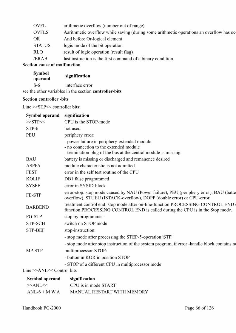
OVFL arithmetic overflow (number out of range) OVFLS Aarithmetic overflow while saving (during some arithmetic operations an overflow has occurred) OR And before Or-logical element STATUS logic mode of the bit operation RLO result of logic operation (result flag)
/ERAB last instruction is the first command of a binary condition Section cause of malfunction
Symbol operand
signification
S-6 interface error see the other variables in the section controller-bits
Section controller -bits
Line >>STP<< controller bits:
Symbol operand signification >>STP<< CPU is the STOP-mode STP-6 not used PEU periphery error:
- power failure in periphery-extended module- no connection to the extended module- termination plug of the bus at the central module is missing.
BAU battery is missing or discharged and remanence desired ASPFA module characteristic is not admitted FEST error in the self test routine of the CPU
KOLIF DB1 false programmed
SYSFE error in SYSID-block
FE-STP error-stop: stop mode caused by NAU (Power failure), PEU (periphery error), BAU (battery is missing), STUEB (BSTACK-overflow), STUEU (ISTACK-overflow), DOPP (double error) or CPU-error
BARBEND treatment control end: stop mode after on-line-function PROCESSING CONTROL END (new start necessary). Is not set if the function PROCESSING CONTROL END is called during the CPU is in the Stop mode.
PG-STP stop by programmer
STP-SCH switch on STOP mode
STP-BEF stop-instruction:
- stop mode after processing the STEP-5-operation 'STP'
- stop mode after stop instruction of the system program, if error -handle block contains no program
MP-STP multiprocessor-STOP:
- button in KOR in position STOP
- STOP of a different CPU in multiprocessor mode Line >>ANL<< Control bits
Symbol operand signification >>ANL<< CPU is in mode START ANL-6 + M W A MANUAL RESTART WITH MEMORY
Handbook PG-2000 Page 66 of 126
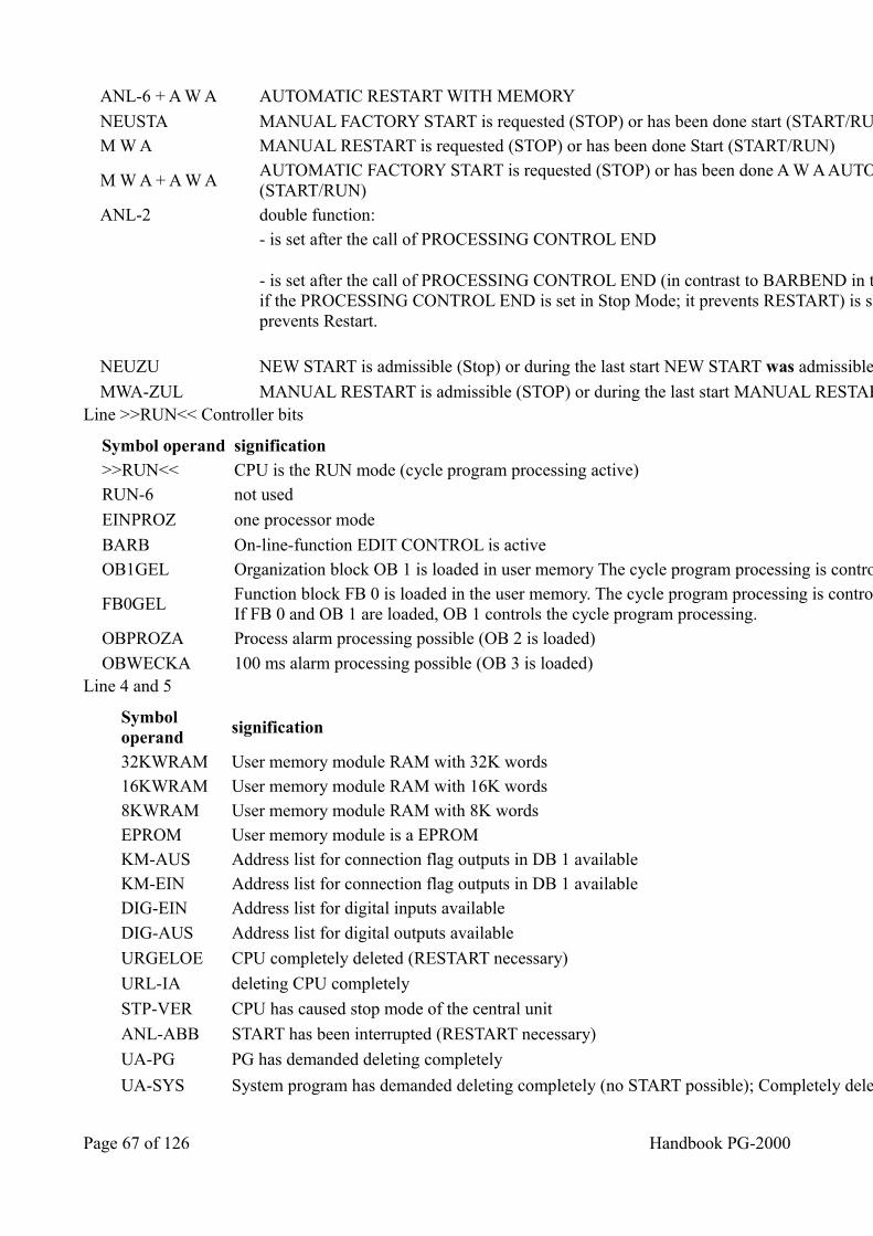
ANL-6 + A W A AUTOMATIC RESTART WITH MEMORY
NEUSTA MANUAL FACTORY START is requested (STOP) or has been done start (START/RUN) M W A MANUAL RESTART is requested (STOP) or has been done Start (START/RUN)
M W A + A W A AUTOMATIC FACTORY START is requested (STOP) or has been done A W A AUTOMATIC NEW START executed (START/RUN)
ANL-2 double function:
- is set after the call of PROCESSING CONTROL END
- is set after the call of PROCESSING CONTROL END (in contrast to BARBEND in the first line of the mask it is also set if the PROCESSING CONTROL END is set in Stop Mode; it prevents RESTART) is set after ‘Compress in Stop Mode’; prevents Restart.
NEUZU NEW START is admissible (Stop) or during the last start NEW START was admissible (START/RUN)
MWA-ZUL MANUAL RESTART is admissible (STOP) or during the last start MANUAL RESTART Line >>RUN<< Controller bits
Symbol operand signification >>RUN<< CPU is the RUN mode (cycle program processing active) RUN-6 not used
EINPROZ one processor mode
BARB On-line-function EDIT CONTROL is active OB1GEL Organization block OB 1 is loaded in user memory The cycle program processing is controlled by OB1
FB0GEL Function block FB 0 is loaded in the user memory. The cycle program processing is controlled by FB 0 if OB 1 is not loaded.If FB 0 and OB 1 are loaded, OB 1 controls the cycle program processing.
OBPROZA Process alarm processing possible (OB 2 is loaded)
OBWECKA 100 ms alarm processing possible (OB 3 is loaded) Line 4 and 5
Symbol operand
signification
32KWRAM User memory module RAM with 32K words 16KWRAM User memory module RAM with 16K words 8KWRAM User memory module RAM with 8K words EPROM User memory module is a EPROM KM-AUS Address list for connection flag outputs in DB 1 available KM-EIN Address list for connection flag outputs in DB 1 available DIG-EIN Address list for digital inputs available
DIG-AUS Address list for digital outputs available
URGELOE CPU completely deleted (RESTART necessary)
URL-IA deleting CPU completely
STP-VER CPU has caused stop mode of the central unit
ANL-ABB START has been interrupted (RESTART necessary)
UA-PG PG has demanded deleting completely
UA-SYS System program has demanded deleting completely (no START possible); Completely deleting has to be done
Page 67 of 126 Handbook PG-2000
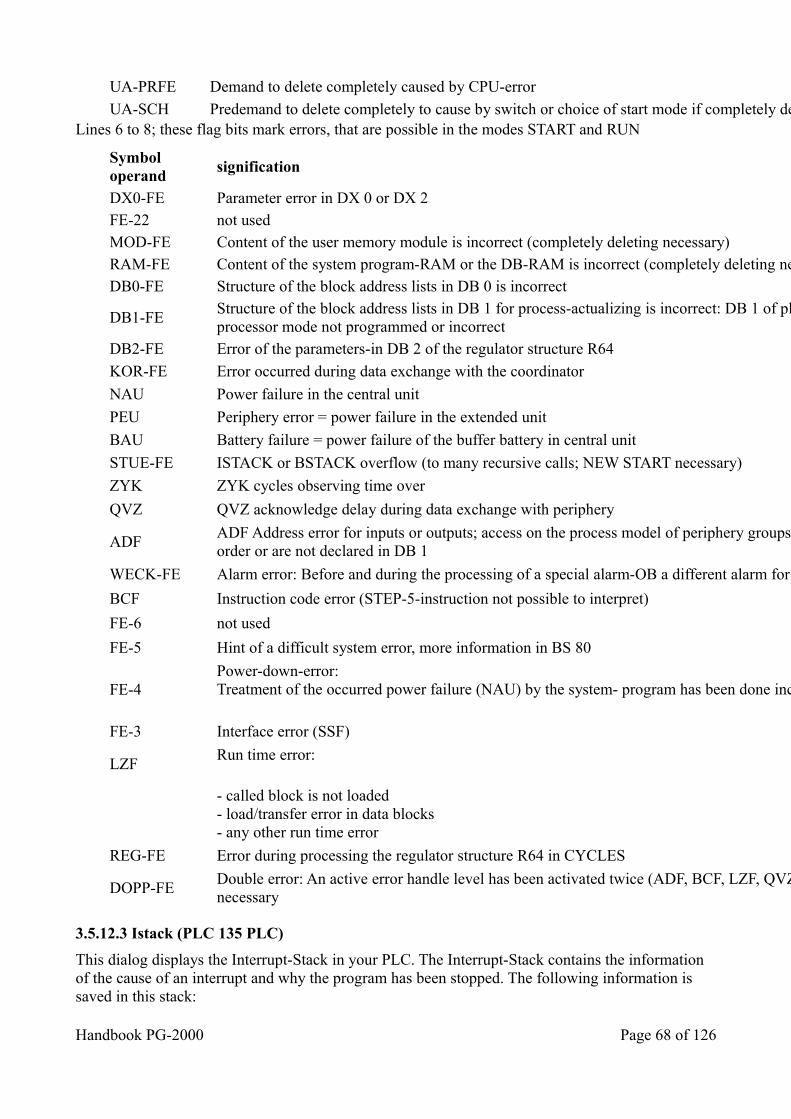
UA-PRFE Demand to delete completely caused by CPU-error
UA-SCH Predemand to delete completely to cause by switch or choice of start mode if completely deleting is not wanted Lines 6 to 8; these flag bits mark errors, that are possible in the modes START and RUN
Symbol operand
signification
DX0-FE Parameter error in DX 0 or DX 2 FE-22 not used MOD-FE Content of the user memory module is incorrect (completely deleting necessary) RAM-FE Content of the system program-RAM or the DB-RAM is incorrect (completely deleting necessary) DB0-FE Structure of the block address lists in DB 0 is incorrect
DB1-FE Structure of the block address lists in DB 1 for process-actualizing is incorrect: DB 1 of plugged coordinator or multi processor mode not programmed or incorrect
DB2-FE Error of the parameters-in DB 2 of the regulator structure R64
KOR-FE Error occurred during data exchange with the coordinator
NAU Power failure in the central unit
PEU Periphery error = power failure in the extended unit
BAU Battery failure = power failure of the buffer battery in central unit
STUE-FE ISTACK or BSTACK overflow (to many recursive calls; NEW START necessary)
ZYK ZYK cycles observing time over
QVZ QVZ acknowledge delay during data exchange with periphery
ADF ADF Address error for inputs or outputs; access on the process model of periphery groups that do not exist or are out of order or are not declared in DB 1
WECK-FE Alarm error: Before and during the processing of a special alarm-OB a different alarm for this OB has been occurred.
BCF Instruction code error (STEP-5-instruction not possible to interpret)
FE-6 not used
FE-5 Hint of a difficult system error, more information in BS 80
FE-4 Power-down-error:Treatment of the occurred power failure (NAU) by the system- program has been done incorrectly. RUN not possible
FE-3 Interface error (SSF)
LZF Run time error:
- called block is not loaded- load/transfer error in data blocks- any other run time error
REG-FE Error during processing the regulator structure R64 in CYCLES
DOPP-FE Double error: An active error handle level has been activated twice (ADF, BCF, LZF, QVZ, REG, ZYK). NEW START necessary
3.5.12.3 Istack (PLC 135 PLC)
This dialog displays the Interrupt-Stack in your PLC. The Interrupt-Stack contains the information of the cause of an interrupt and why the program has been stopped. The following information is saved in this stack:
Handbook PG-2000 Page 68 of 126
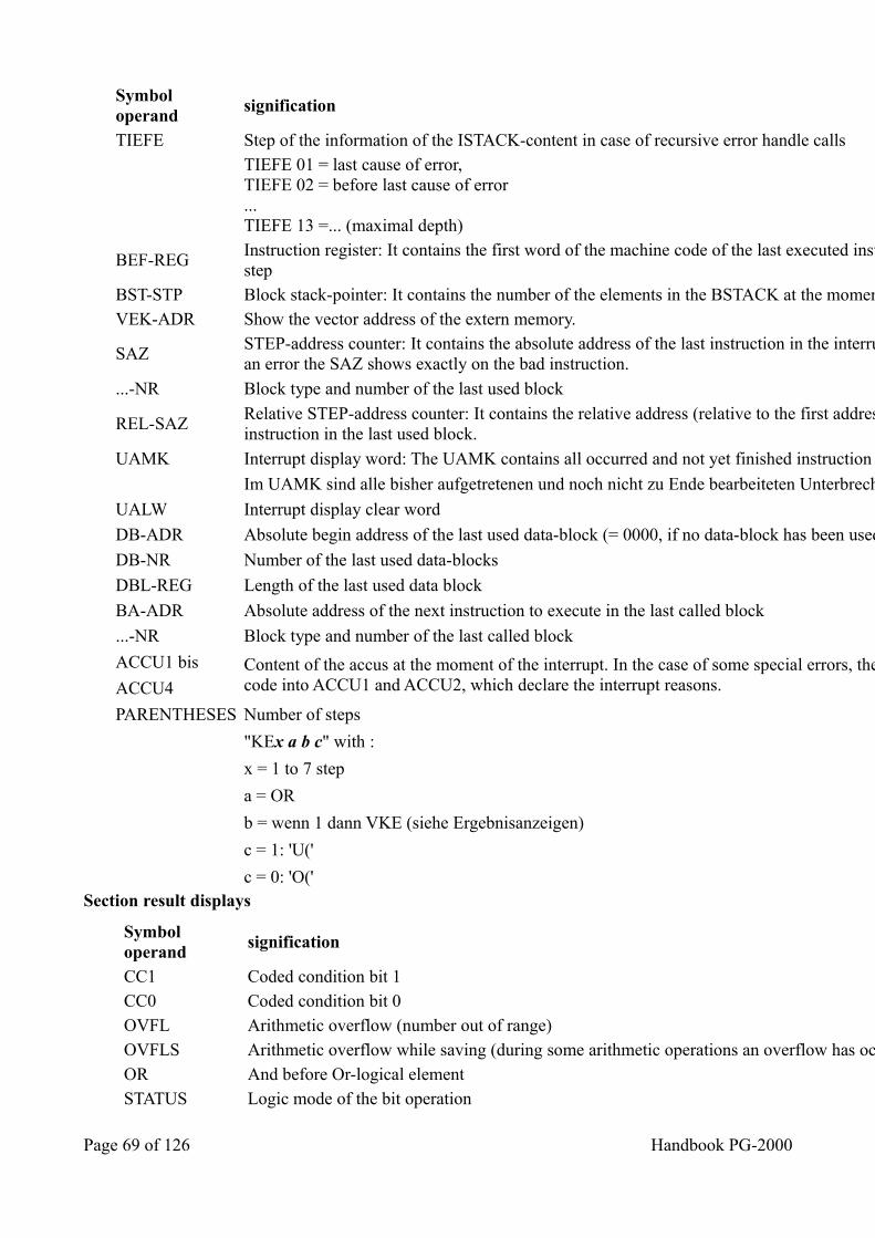
Symbol operand
signification
TIEFE Step of the information of the ISTACK-content in case of recursive error handle calls
TIEFE 01 = last cause of error,TIEFE 02 = before last cause of error...TIEFE 13 =... (maximal depth)
BEF-REG Instruction register: It contains the first word of the machine code of the last executed instruction of the interrupted programstep
BST-STP Block stack-pointer: It contains the number of the elements in the BSTACK at the moment of the interrupted program step VEK-ADR Show the vector address of the extern memory.
SAZ STEP-address counter: It contains the absolute address of the last instruction in the interrupted program step. In the case of an error the SAZ shows exactly on the bad instruction.
...-NR Block type and number of the last used block
REL-SAZ Relative STEP-address counter: It contains the relative address (relative to the first address of the block) of the last instruction in the last used block.
UAMK Interrupt display word: The UAMK contains all occurred and not yet finished instruction causes.
Im UAMK sind alle bisher aufgetretenen und noch nicht zu Ende bearbeiteten Unterbrechungsursachen angezeigt.
UALW Interrupt display clear word
DB-ADR Absolute begin address of the last used data-block (= 0000, if no data-block has been used)
DB-NR Number of the last used data-blocks
DBL-REG Length of the last used data block
BA-ADR Absolute address of the next instruction to execute in the last called block
...-NR Block type and number of the last called block
ACCU1 bis Content of the accus at the moment of the interrupt. In the case of some special errors, the system program saves an error code into ACCU1 and ACCU2, which declare the interrupt reasons. ACCU4
PARENTHESES Number of steps
"KEx a b c" with :
x = 1 to 7 step
a = OR
b = wenn 1 dann VKE (siehe Ergebnisanzeigen)
c = 1: 'U('
c = 0: 'O(' Section result displays
Symbol operand
signification
CC1 Coded condition bit 1 CC0 Coded condition bit 0 OVFL Arithmetic overflow (number out of range) OVFLS Arithmetic overflow while saving (during some arithmetic operations an overflow has occurred) OR And before Or-logical element STATUS Logic mode of the bit operation
Page 69 of 126 Handbook PG-2000
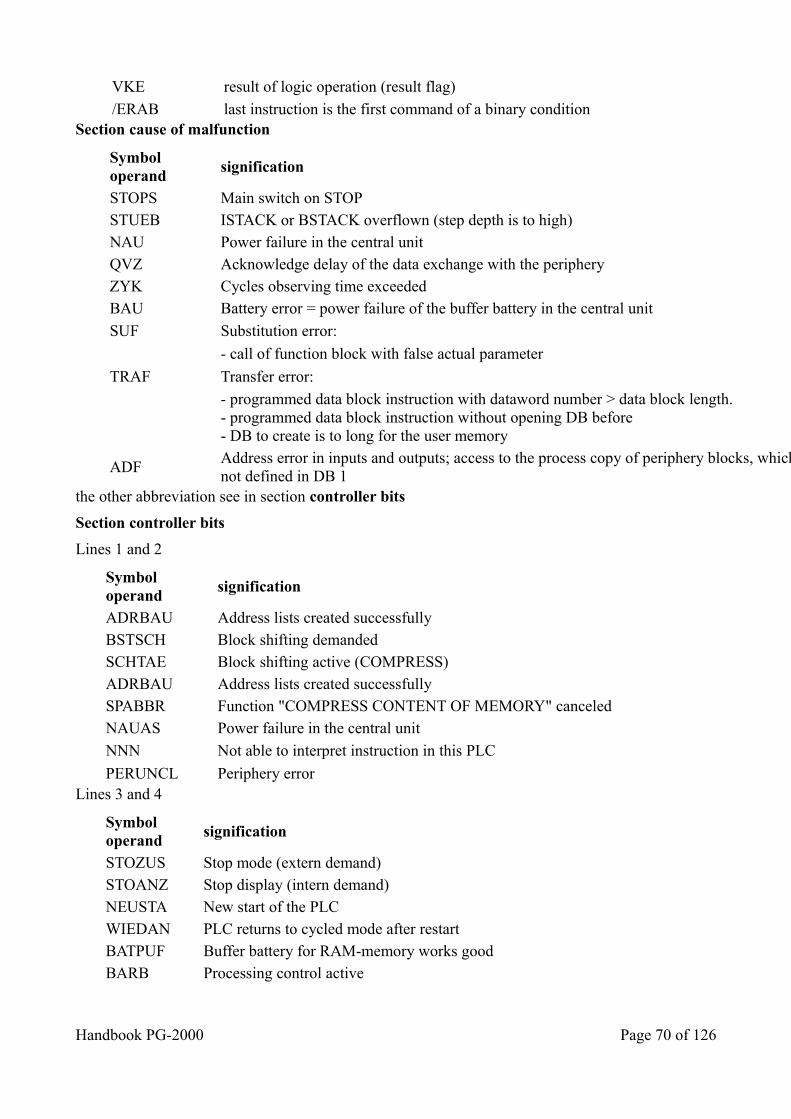
VKE result of logic operation (result flag)
/ERAB last instruction is the first command of a binary condition Section cause of malfunction
Symbol operand
signification
STOPS Main switch on STOP STUEB ISTACK or BSTACK overflown (step depth is to high) NAU Power failure in the central unit QVZ Acknowledge delay of the data exchange with the periphery ZYK Cycles observing time exceeded BAU Battery error = power failure of the buffer battery in the central unit
SUF Substitution error:
- call of function block with false actual parameter
TRAF Transfer error:
- programmed data block instruction with dataword number > data block length.- programmed data block instruction without opening DB before- DB to create is to long for the user memory
ADF Address error in inputs and outputs; access to the process copy of periphery blocks, which do not exist or are out of order ornot defined in DB 1
the other abbreviation see in section controller bits
Section controller bits
Lines 1 and 2
Symbol operand
signification
ADRBAU Address lists created successfully BSTSCH Block shifting demanded SCHTAE Block shifting active (COMPRESS) ADRBAU Address lists created successfully SPABBR Function "COMPRESS CONTENT OF MEMORY" canceled NAUAS Power failure in the central unit
NNN Not able to interpret instruction in this PLC
PERUNCL Periphery error Lines 3 and 4
Symbol operand
signification
STOZUS Stop mode (extern demand) STOANZ Stop display (intern demand) NEUSTA New start of the PLC WIEDAN PLC returns to cycled mode after restart BATPUF Buffer battery for RAM-memory works good BARB Processing control active
Handbook PG-2000 Page 70 of 126
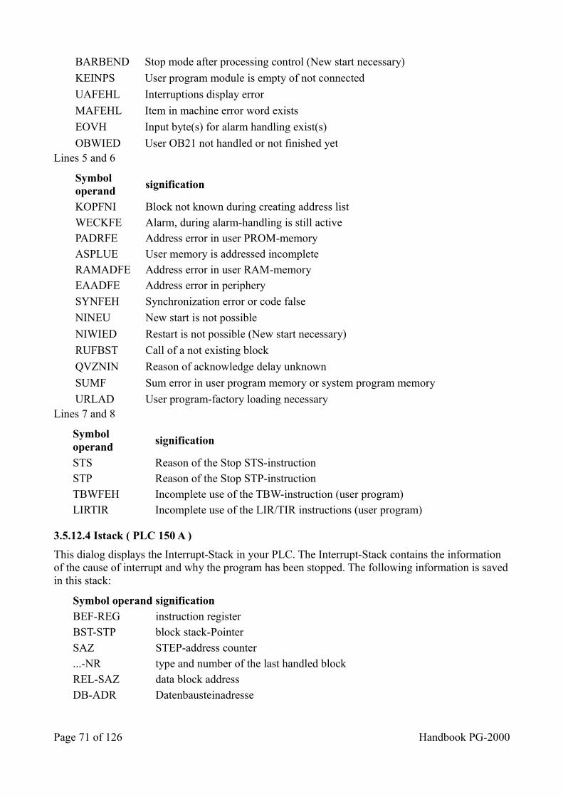
BARBEND Stop mode after processing control (New start necessary)
KEINPS User program module is empty of not connected
UAFEHL Interruptions display error
MAFEHL Item in machine error word exists
EOVH Input byte(s) for alarm handling exist(s)
OBWIED User OB21 not handled or not finished yet Lines 5 and 6
Symbol operand
signification
KOPFNI Block not known during creating address list WECKFE Alarm, during alarm-handling is still active PADRFE Address error in user PROM-memory ASPLUE User memory is addressed incomplete RAMADFE Address error in user RAM-memory EAADFE Address error in periphery
SYNFEH Synchronization error or code false
NINEU New start is not possible
NIWIED Restart is not possible (New start necessary)
RUFBST Call of a not existing block
QVZNIN Reason of acknowledge delay unknown
SUMF Sum error in user program memory or system program memory
URLAD User program-factory loading necessary Lines 7 and 8
Symbol operand
signification
STS Reason of the Stop STS-instruction STP Reason of the Stop STP-instruction TBWFEH Incomplete use of the TBW-instruction (user program) LIRTIR Incomplete use of the LIR/TIR instructions (user program)
3.5.12.4 Istack ( PLC 150 A )
This dialog displays the Interrupt-Stack in your PLC. The Interrupt-Stack contains the information of the cause of interrupt and why the program has been stopped. The following information is savedin this stack:
Symbol operand signification BEF-REG instruction register BST-STP block stack-Pointer SAZ STEP-address counter ...-NR type and number of the last handled block REL-SAZ data block address DB-ADR Datenbausteinadresse
Page 71 of 126 Handbook PG-2000
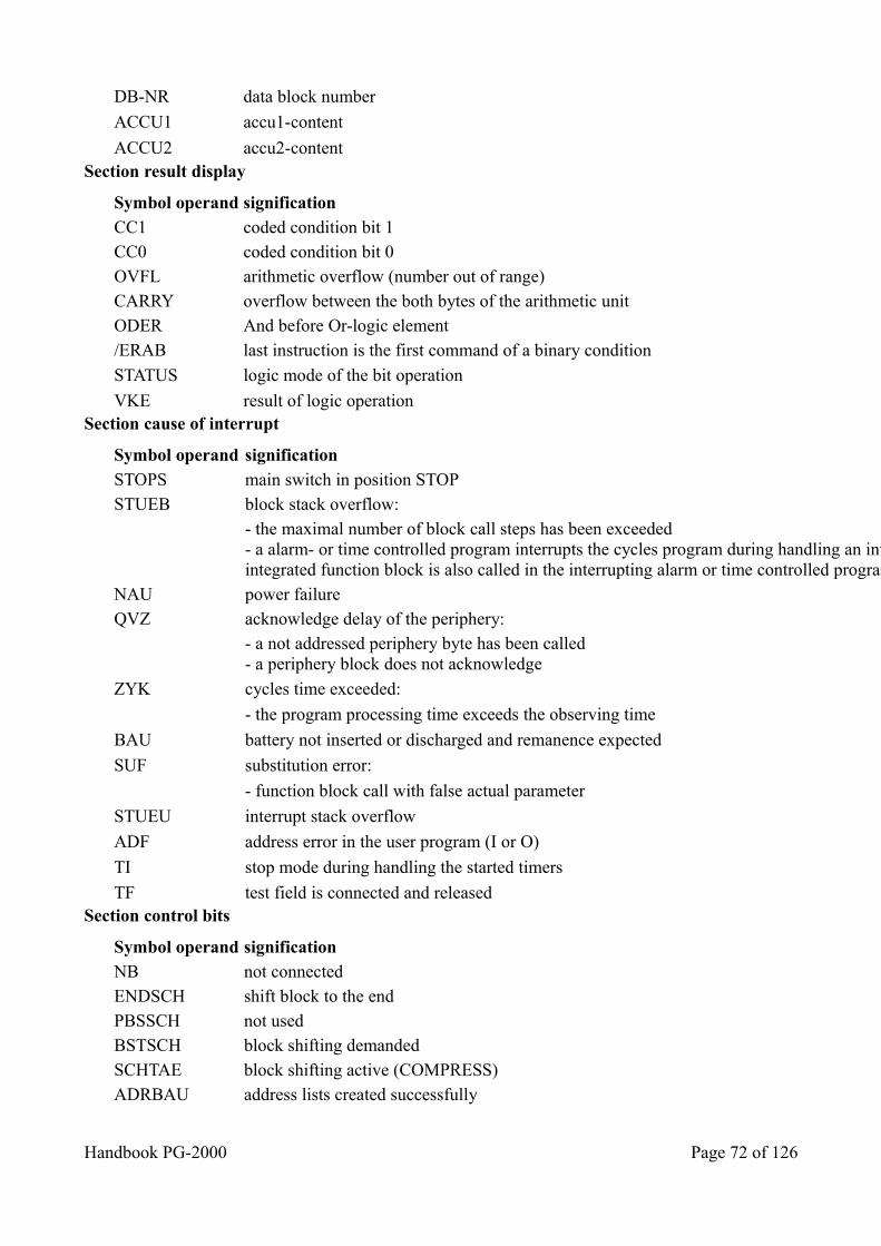
DB-NR data block number
ACCU1 accu1-content
ACCU2 accu2-content Section result display
Symbol operand signification CC1 coded condition bit 1 CC0 coded condition bit 0 OVFL arithmetic overflow (number out of range) CARRY overflow between the both bytes of the arithmetic unit ODER And before Or-logic element /ERAB last instruction is the first command of a binary condition
STATUS logic mode of the bit operation
VKE result of logic operation Section cause of interrupt
Symbol operand signification STOPS main switch in position STOP STUEB block stack overflow:
- the maximal number of block call steps has been exceeded- a alarm- or time controlled program interrupts the cycles program during handling an integrated function block and a integrated function block is also called in the interrupting alarm or time controlled program.
NAU power failure QVZ acknowledge delay of the periphery:
- a not addressed periphery byte has been called- a periphery block does not acknowledge
ZYK cycles time exceeded:
- the program processing time exceeds the observing time
BAU battery not inserted or discharged and remanence expected
SUF substitution error:
- function block call with false actual parameter
STUEU interrupt stack overflow
ADF address error in the user program (I or O)
TI stop mode during handling the started timers
TF test field is connected and released Section control bits
Symbol operand signification NB not connected ENDSCH shift block to the end PBSSCH not used BSTSCH block shifting demanded SCHTAE block shifting active (COMPRESS) ADRBAU address lists created successfully
Handbook PG-2000 Page 72 of 126
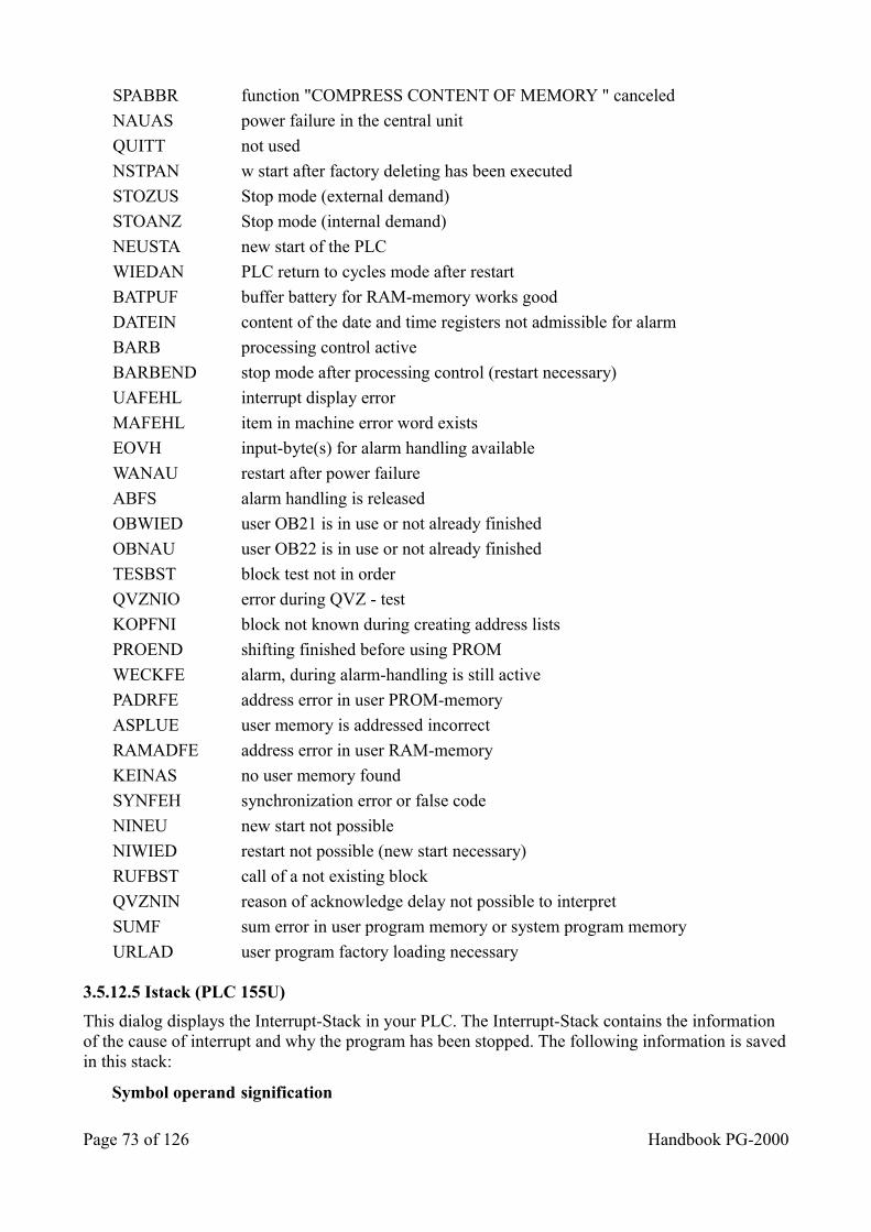
SPABBR function "COMPRESS CONTENT OF MEMORY " canceled
NAUAS power failure in the central unit
QUITT not used
NSTPAN w start after factory deleting has been executed
STOZUS Stop mode (external demand)
STOANZ Stop mode (internal demand)
NEUSTA new start of the PLC
WIEDAN PLC return to cycles mode after restart
BATPUF buffer battery for RAM-memory works good
DATEIN content of the date and time registers not admissible for alarm
BARB processing control active
BARBEND stop mode after processing control (restart necessary)
UAFEHL interrupt display error
MAFEHL item in machine error word exists
EOVH input-byte(s) for alarm handling available
WANAU restart after power failure
ABFS alarm handling is released
OBWIED user OB21 is in use or not already finished
OBNAU user OB22 is in use or not already finished
TESBST block test not in order
QVZNIO error during QVZ - test
KOPFNI block not known during creating address lists
PROEND shifting finished before using PROM
WECKFE alarm, during alarm-handling is still active
PADRFE address error in user PROM-memory
ASPLUE user memory is addressed incorrect
RAMADFE address error in user RAM-memory
KEINAS no user memory found
SYNFEH synchronization error or false code
NINEU new start not possible
NIWIED restart not possible (new start necessary)
RUFBST call of a not existing block
QVZNIN reason of acknowledge delay not possible to interpret
SUMF sum error in user program memory or system program memory
URLAD user program factory loading necessary
3.5.12.5 Istack (PLC 155U)
This dialog displays the Interrupt-Stack in your PLC. The Interrupt-Stack contains the information of the cause of interrupt and why the program has been stopped. The following information is savedin this stack:
Symbol operand signification
Page 73 of 126 Handbook PG-2000
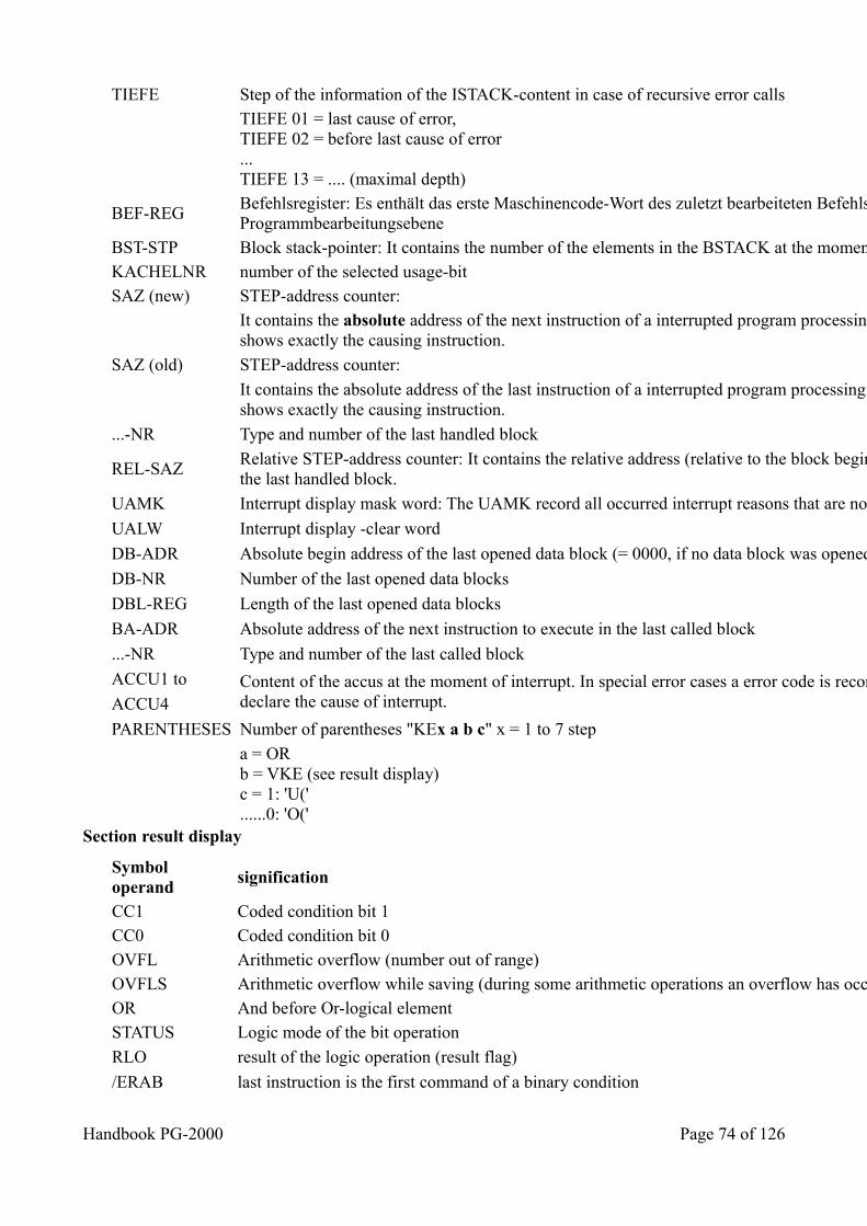
TIEFE Step of the information of the ISTACK-content in case of recursive error calls
TIEFE 01 = last cause of error,TIEFE 02 = before last cause of error...TIEFE 13 = .... (maximal depth)
BEF-REG Befehlsregister: Es enthält das erste Maschinencode-Wort des zuletzt bearbeiteten Befehls einer unterbrochenen Programmbearbeitungsebene
BST-STP Block stack-pointer: It contains the number of the elements in the BSTACK at the moment of the interrupted program step. KACHELNR number of the selected usage-bit SAZ (new) STEP-address counter:
It contains the absolute address of the next instruction of a interrupted program processing step. In case of an error the SAZ shows exactly the causing instruction.
SAZ (old) STEP-address counter:
It contains the absolute address of the last instruction of a interrupted program processing step. In case of an error the SAZ shows exactly the causing instruction.
...-NR Type and number of the last handled block
REL-SAZ Relative STEP-address counter: It contains the relative address (relative to the block begin address) of the next instruction inthe last handled block.
UAMK Interrupt display mask word: The UAMK record all occurred interrupt reasons that are not already finished
UALW Interrupt display -clear word
DB-ADR Absolute begin address of the last opened data block (= 0000, if no data block was opened)
DB-NR Number of the last opened data blocks
DBL-REG Length of the last opened data blocks
BA-ADR Absolute address of the next instruction to execute in the last called block
...-NR Type and number of the last called block
ACCU1 to Content of the accus at the moment of interrupt. In special error cases a error code is recorded in ACCU1 and ACCU2 that declare the cause of interrupt. ACCU4
PARENTHESES Number of parentheses "KEx a b c" x = 1 to 7 step
a = ORb = VKE (see result display)c = 1: 'U('......0: 'O('
Section result display
Symbol operand
signification
CC1 Coded condition bit 1 CC0 Coded condition bit 0 OVFL Arithmetic overflow (number out of range) OVFLS Arithmetic overflow while saving (during some arithmetic operations an overflow has occurred) OR And before Or-logical element STATUS Logic mode of the bit operation
RLO result of the logic operation (result flag)
/ERAB last instruction is the first command of a binary condition
Handbook PG-2000 Page 74 of 126
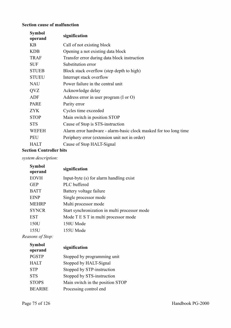
Section cause of malfunction
Symbol operand
signification
KB Call of not existing block KDB Opening a not existing data block TRAF Transfer error during data block instruction SUF Substitution error STUEB Block stack overflow (step depth to high) STUEU Interrupt stack overflow
NAU Power failure in the central unit
QVZ Acknowledge delay
ADF Address error in user program (I or O)
PARE Parity error
ZYK Cycles time exceeded
STOP Main switch in position STOP
STS Cause of Stop is STS-instruction
WEFEH Alarm error hardware - alarm-basic clock masked for too long time
PEU Periphery error (extension unit not in order)
HALT Cause of Stop HALT-Signal Section Controller bits
system description:
Symbol operand
signification
EOVH Input-byte (s) for alarm handling exist GEP PLC buffered BATT Battery voltage failure EINP Single processor mode MEHRP Multi processor mode SYNCR Start synchronization in multi processor mode
EST Mode T E S T in multi processor mode
150U 150U Mode
155U 155U Mode Reasons of Stop:
Symbol operand
signification
PGSTP Stopped by programming unit HALT Stopped by HALT-Signal STP Stopped by STP-instruction STS Stopped by STS-instruction STOPS Main switch in the position STOP BEARBE Processing control end
Page 75 of 126 Handbook PG-2000
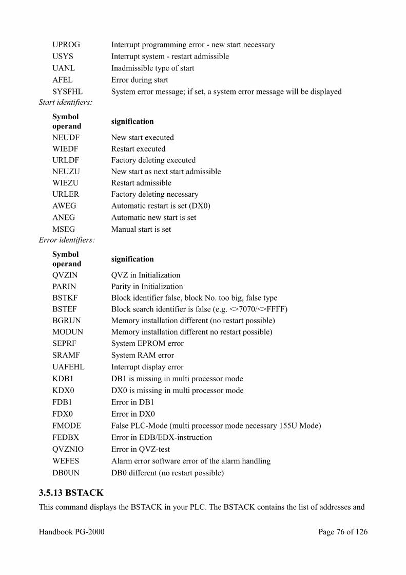
UPROG Interrupt programming error - new start necessary
USYS Interrupt system - restart admissible
UANL Inadmissible type of start
AFEL Error during start
SYSFHL System error message; if set, a system error message will be displayed Start identifiers:
Symbol operand
signification
NEUDF New start executed WIEDF Restart executed URLDF Factory deleting executed NEUZU New start as next start admissible WIEZU Restart admissible URLER Factory deleting necessary
AWEG Automatic restart is set (DX0)
ANEG Automatic new start is set
MSEG Manual start is set Error identifiers:
Symbol operand
signification
QVZIN QVZ in Initialization PARIN Parity in Initialization BSTKF Block identifier false, block No. too big, false type BSTEF Block search identifier is false (e.g. <>7070/<>FFFF) BGRUN Memory installation different (no restart possible) MODUN Memory installation different no restart possible)
SEPRF System EPROM error
SRAMF System RAM error
UAFEHL Interrupt display error
KDB1 DB1 is missing in multi processor mode
KDX0 DX0 is missing in multi processor mode
FDB1 Error in DB1
FDX0 Error in DX0
FMODE False PLC-Mode (multi processor mode necessary 155U Mode)
FEDBX Error in EDB/EDX-instruction
QVZNIO Error in QVZ-test
WEFES Alarm error software error of the alarm handling
DB0UN DB0 different (no restart possible)
3.5.13 BSTACK
This command displays the BSTACK in your PLC. The BSTACK contains the list of addresses and
Handbook PG-2000 Page 76 of 126
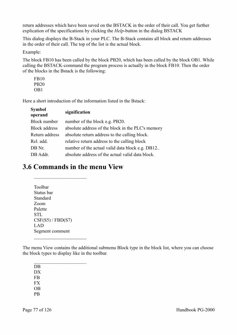
return addresses which have been saved on the BSTACK in the order of their call. You get further explication of the specifications by clicking the Help-button in the dialog BSTACK
This dialog displays the B-Stack in your PLC. The B-Stack contains all block and return addresses in the order of their call. The top of the list is the actual block.
Example:
The block FB10 has been called by the block PB20, which has been called by the block OB1. Whilecalling the BSTACK-command the program process is actually in the block FB10. Then the order of the blocks in the Bstack is the following:
FB10PB20OB1
Here a short introduction of the information listed in the Bstack:
Symbol operand
signification
Block number number of the block e.g. PB20. Block address absolute address of the block in the PLC's memory Return address absolute return address to the calling block. Rel. add. relative return address to the calling block DB Nr. number of the actual valid data block e.g. DB12.. DB Addr. absolute address of the actual valid data block.
3.6 Commands in the menu View ______________________
ToolbarStatus barStandardZoomPaletteSTLCSF(S5) / FBD(S7)LADSegment comment______________________
The menu View contains the additional submenu Block type in the block list, where you can choosethe block types to display like in the toolbar.
______________________DBDXFBFXOBPB
Page 77 of 126 Handbook PG-2000
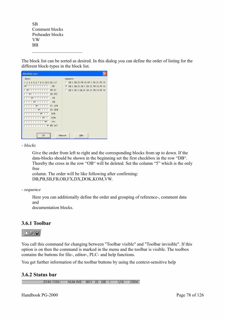
SBComment blocksPreheader blocksVWBB______________________
The block list can be sorted as desired. In this dialog you can define the order of listing for the different block-types in the block list.
- blocks
Give the order from left to right and the corresponding blocks from up to down. If thedata-blocks should be shown in the beginning set the first checkbox in the row “DB“.Thereby the cross in the row “OB“ will be deleted. Set the column “5” which is the onlyfreecolumn. The order will be like following after confirming:DB,PB,SB,FB,OB,FX,DX,DOK,KOM,VW.
- sequence
Here you can additionally define the order and grouping of reference-, comment data anddocumentation blocks.
3.6.1 Toolbar
You call this command for changing between "Toolbar visible" and "Toolbar invisible". If this option is on then the command is marked in the menu and the toolbar is visible. The toolbox contains the buttons for file-, editor-, PLC- and help functions.
You get further information of the toolbar buttons by using the context-sensitive help
3.6.2 Status bar
Handbook PG-2000 Page 78 of 126
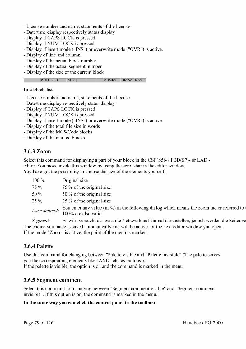
- License number and name, statements of the license- Date/time display respectively status display- Display if CAPS LOCK is pressed- Display if NUM LOCK is pressed- Display if insert mode ("INS") or overwrite mode ("OVR") is active.- Display of line and column- Display of the actual block number- Display of the actual segment number- Display of the size of the current block
In a block-list
- License number and name, statements of the license- Date/time display respectively status display- Display if CAPS LOCK is pressed- Display if NUM LOCK is pressed- Display if insert mode ("INS") or overwrite mode ("OVR") is active.- Display of the total file size in words- Display of the MC5-Code blocks- Display of the marked blocks
3.6.3 Zoom
Select this command for displaying a part of your block in the CSF(S5)- / FBD(S7)- or LAD - editor. You move inside this window by using the scroll-bar in the editor window.You have got the possibility to choose the size of the elements yourself.
100 % Original size 75 % 75 % of the original size 50 % 50 % of the original size 25 % 25 % of the original size
User defined: You enter any value (in %) in the following dialog which means the zoom factor referred to the original size. Values above 100% are also valid.
Segment: Es wird versucht das gesamte Netzwerk auf einmal darzustellen, jedoch werden die Seitenverhältnisse gewahrt. The choice you made is saved automatically and will be active for the next editor window you open.If the mode "Zoom" is active, the point of the menu is marked.
3.6.4 Palette
Use this command for changing between "Palette visible and "Palette invisible" (The palette serves you the corresponding elements like "AND" etc. as buttons.).If the palette is visible, the option is on and the command is marked in the menu.
3.6.5 Segment comment
Select this command for changing between "Segment comment visible" and "Segment comment invisible". If this option is on, the command is marked in the menu.
In the same way you can click the control panel in the toolbar:
Page 79 of 126 Handbook PG-2000
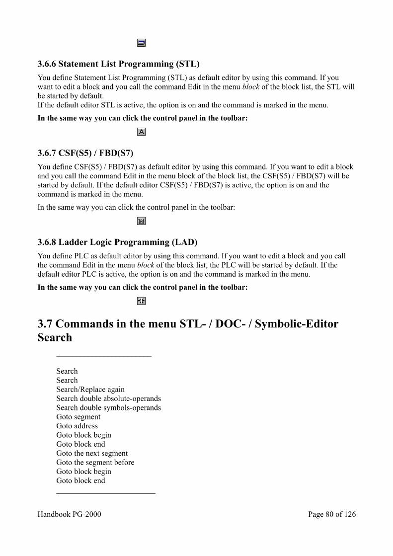
3.6.6 Statement List Programming (STL)
You define Statement List Programming (STL) as default editor by using this command. If you want to edit a block and you call the command Edit in the menu block of the block list, the STL willbe started by default.If the default editor STL is active, the option is on and the command is marked in the menu.
In the same way you can click the control panel in the toolbar:
3.6.7 CSF(S5) / FBD(S7)
You define CSF(S5) / FBD(S7) as default editor by using this command. If you want to edit a block and you call the command Edit in the menu block of the block list, the CSF(S5) / FBD(S7) will be started by default. If the default editor CSF(S5) / FBD(S7) is active, the option is on and the command is marked in the menu.
In the same way you can click the control panel in the toolbar:
3.6.8 Ladder Logic Programming (LAD)
You define PLC as default editor by using this command. If you want to edit a block and you call the command Edit in the menu block of the block list, the PLC will be started by default. If the default editor PLC is active, the option is on and the command is marked in the menu.
In the same way you can click the control panel in the toolbar:
3.7 Commands in the menu STL- / DOC- / Symbolic-Editor Search
________________________
SearchSearchSearch/Replace againSearch double absolute-operandsSearch double symbols-operandsGoto segmentGoto addressGoto block beginGoto block endGoto the next segmentGoto the segment beforeGoto block beginGoto block end_________________________
Handbook PG-2000 Page 80 of 126
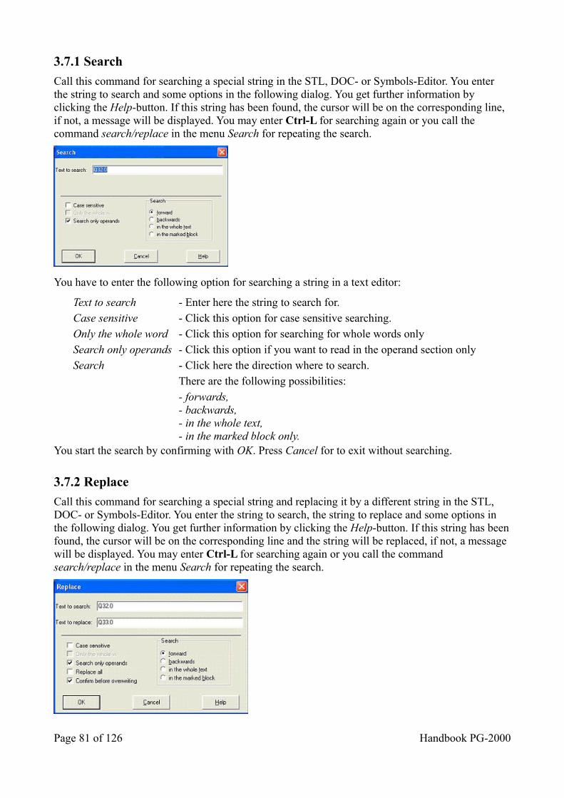
3.7.1 Search
Call this command for searching a special string in the STL, DOC- or Symbols-Editor. You enter the string to search and some options in the following dialog. You get further information by clicking the Help-button. If this string has been found, the cursor will be on the corresponding line, if not, a message will be displayed. You may enter Ctrl-L for searching again or you call the command search/replace in the menu Search for repeating the search.
You have to enter the following option for searching a string in a text editor:
Text to search - Enter here the string to search for. Case sensitive - Click this option for case sensitive searching. Only the whole word - Click this option for searching for whole words only Search only operands - Click this option if you want to read in the operand section only Search - Click here the direction where to search. There are the following possibilities:
- forwards,- backwards,- in the whole text,- in the marked block only.
You start the search by confirming with OK. Press Cancel for to exit without searching.
3.7.2 Replace
Call this command for searching a special string and replacing it by a different string in the STL, DOC- or Symbols-Editor. You enter the string to search, the string to replace and some options in the following dialog. You get further information by clicking the Help-button. If this string has beenfound, the cursor will be on the corresponding line and the string will be replaced, if not, a message will be displayed. You may enter Ctrl-L for searching again or you call the command search/replace in the menu Search for repeating the search.
Page 81 of 126 Handbook PG-2000
You have to enter the following option for searching a string in a text editor:
Text to search - Enter here the string to search for. Text to replace - Enter here the string to replace the searched string. Case sensitive - Click this option for case sensitive searching. Only the whole word - Click this option for searching for whole words only Search only operands - Click this option if you want to read in the operand section only
Replace all - Click this option if you are sure that you want replace all the strings. The position will not be displayed and you cannot confirm or cancel the action of replacing.
Confirm before overwriting
Click this option if you want to be ask before replacing a string in the text. The position will not be displayed and you must confirm or cancel the action of replacing.
Search - Click here the direction where to search. There are the following possibilities:
- forwards,- backwards,- in the whole text,- in the marked block only.
You start the search by confirming with OK. Press Cancel/ for to exit without searching.
3.7.3 Search/Repeat again
Call this command for repeating the search you started last. You may also employ the hot-key Ctrl-L.
3.7.4 Search double absolute-operands
This command is offered to you by the symbols-editor for finding the absolute operands that are used more than one time. The cursor moves onto the list with the first of the operand that is used more than one time. You correct this and call this function again. You repeat this until there is not any operand used more than one time any more.
_____________________________________________________________________________
Example:
The actual content of symbols-editor is the following:
I 2.1 DOORI 3.4 PUMPI 2.1 DOOR 1 CHECK
The cursor is in the last line on IW 2.1 after calling this command. This absolute operand has been used inadmissible twice with the same symbols name._____________________________________________________________________________
3.7.5 Search double symbols-operand
This command is offered to you by the symbols-editor for finding the absolute operands that are used more than one time. The cursor moves onto the list with the first of the operand that is used
Handbook PG-2000 Page 82 of 126
more than one time. You correct this and call this function again. You repeat this until there is not any operand used more than one time any more._____________________________________________________________________________
The actual content of symbols-editor is the following:
I 2.1 DOOR1I 3.4 PUMPI 5.1 DOOR1
The cursor is in the last line on I 2.1 after calling this command. This absolute operand has been used inadmissible twice with the same symbols name._____________________________________________________________________________
3.7.6 View first/second
You can change among the operands you have found by calling the command Search double absolute operands respectively Search double symbols operands.
3.7.7 Goto segment
This command sets the cursor to the beginning of a special segment. When you call this command adialog appears, in which you can enter the segment's number. You confirm by pressing OK. Then the cursor is on the first instruction of the segment t1hat you have selected.
3.7.8 Goto address
This command sets the cursor onto the beginning of a STL-instruction. When you call this command a dialog appears, in which you can enter the address of the instruction that you want. Thisaddress is exactly that address that you get by calling the menu Options/Output address. Then the cursor is on the first instruction of the segment that you have selected. You confirm by pressing OK.The cursor is set this address by this command.
3.7.9 Goto block begin
This command sets the cursor to the beginning of a block which is defined by you. You can define ablock by using the commands Block begin, Block end in the menu Edit->.
3.7.10 Goto block end
This command sets the cursor to the end of a defined block. You define a block by using the commands Block begin, Block end in the menu Edit->.
3.7.11 Goto the next segment
This command sets the cursor to the begin of the next segment. The next segment is the segment after the actual.
3.7.12 Goto the segment before
This command sets the cursor to the begin of the segment before. The segment before is the segment before the actual.
Page 83 of 126 Handbook PG-2000
3.7.13 Insert segment
This command inserts a new, empty segment at the cursor's actual position.
3.7.14 Delete segment
This command deletes the segment at the cursor's actual position.
3.7.15 Goto begin block
This command sets the cursor to the begin of the block that process now.
3.7.16 Goto block end
This command sets the cursor to the end of the block that process now.
3.8 Commands in the STL/DOC/Symbols-Editor-menu Edit ______________________
Cut outCopyPaste fromDelete
Block beginBlock endUnmark blocks
Paste lineDelete line
Paste program lineDelete program linePaste comment lineDelete comment line
Assort to absolute operandsAssort to symbols operands
SEG <-> LINE______________________
3.8.1 Block begin
This commands marks the begin of a text block. You mark the end of the selected block by using the command Block end. The text that you defined like this is displayed in a different color. You cantreat this text by calling the commands of the menu Edit.
Handbook PG-2000 Page 84 of 126
3.8.2 Block end
This commands marks the end of a text block. You mark the begin of the selected block by using the command Block begin. The text that you defined like this is displayed in a different color. You can treat this text by calling the commands of the menu Edit.
3.8.3 Unmark blocks
This command unmarks the actual text block.
3.8.4 Cut out
This command cuts the marked part out of the text and copies it to the clip-board. You get this part of the text back from the clip-board for appending it in your text by calling the commandPaste from in the menu Edit.
In the same way you can click the control panel in the toolbar:
3.8.5 Copy
This command copies the marked part of the text to the clip-board. The text will not be changed. You get this part of the text from the clip-board for appending it in your text by calling the commandPaste from in the menu Edit.
In the same way you can click the control panel in the toolbar:
3.8.6 Paste
This command appends a text from the clip-board into the actual text at the actual cursor position. You call the commands Cut out or Copy in the menu Edit for copying a part of a text to the clip-board.
In the same way you can click the control panel in the toolbar:
3.8.7 Delete
You call this command for deleting the marked part of the text without copying it to the clip-board. The actual content in the clip-board rests the same as before.
3.8.8 Paste line
This command appends an empty line at the cursor position.
3.8.9 Delete line
This command deletes the line of the cursor position.
Page 85 of 126 Handbook PG-2000
3.8.10 Paste program line
This command appends an empty line at the actual line without shifting the comments.
3.8.11 Delete program line
This command deletes the actual program line without shifting the comments. If there is a commentin the last line of the actual segment, you have to acknowledge it before.
3.8.12 Paste comment line
This command appends an empty line at the actual line without shifting the program text. The comments from the actual line to the end will be shifted down a line. If there is a comment in the last line of the actual segment, you have to acknowledge it before.
3.8.13 Delete comment line
This command deletes the comment in the actual line without shifting the program text. The comments from the actual line to the end will be shifted up a line.
3.8.14 Assort to absolute operands
This command sorts the symbols list to absolute operands. It is available in a symbol editor only.
The assortment happens in different sections, this means each section of the symbols list will be sorted. A section means all lines between two section separators. This are pure comment lines (lines which begin with a ' ; ') and lines with an empty absolute operand. In this way, the parts separated by comment lines are preserved in the symbols list.
3.8.15 Assort to symbols operands
This command assorts the symbols list to symbols operands. It is available in the symbols editor only.
The assortment happens in different sections, this means each section of the symbols list will be sorted. A section means all lines between two section separators. This are pure comment lines (lines which begin with a ' ; ') and lines with an empty absolute operand. In this way, the parts separated by comment lines are preserved in the symbols list.
3.8.16 SEG <-> LINE
You can convert a segment comment into a block comment by calling this command. This command is available only if you edit a block of the types FK, FKX, OK, PK or SK. This commandis not available for the first comment line of a segment, because there has to be always a segment comment in the first line of a comment block.
3.9 Commands in the Force-Variable-menu Status _____________________
Start cyclesStop cycles
Handbook PG-2000 Page 86 of 126
Send values to PLCConfiguration dataloggerDatalogger______________________
3.9.1 Start cycles
This command starts the PG-2000 cycles, which reads in the PLC the actual values of the selected variables. You select this variables in the list that you get by calling the command Force variables. This means you can display only these variables that you have defined in the list. You cannot define more than 10 variables in the list.
Important:The PLC must be in the RUN-mode when you start the cycles for watching the changing values. If the PLC is the STOP-mode, only the static values are displayed but the PLC will not be set on the RUN-mode. Use the command Start PLC in the menu PLC functions or activates the button in the tool-bar for starting the PLC.
In the same way you can click the control panel in the toolbar:
If the datalogger is on, the values will be recorded in the datalogger. The values will be recorded in a file, in a solid line recorder or in both, which depends of the configuration of the datalogger. Use the command Datalogger in the menu Status.
3.9.2 Stop cycles
This command stops the PG-2000 cycles, which dates up the values of the selected variables. So thevariables will not be updated any longer. This variables are selected in the variables list that you get by calling the command Force variables.
Important:If the PLC gets into the STOP-mode, these cycles will not stop automatically but the static values in thePLC will be read and displayed.
In the same way you can click the control panel in the toolbar:
3.9.3 Send values to PLC
This command saves the values of the selected variables into the PLC. The variables have been select by calling the command Force-variables. It does not matter if the PLC is in the STOP-mode or the RUN-mode. After the transfer of these values, the cycles will be started.
In the same way you can click the control panel in the toolbar:
3.9.4 Datalogger configuration
see chapter:
With this command you can set the properties of the data-logger. You can record and display the
Page 87 of 126 Handbook PG-2000
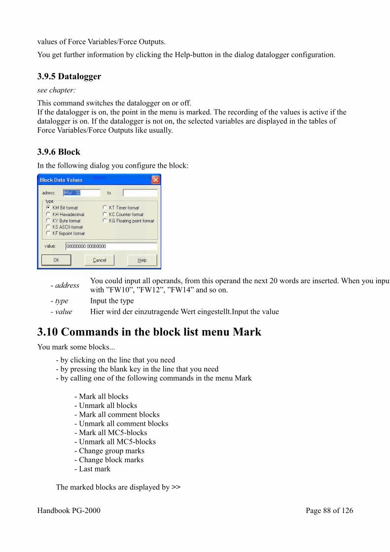
values of Force Variables/Force Outputs.
You get further information by clicking the Help-button in the dialog datalogger configuration.
3.9.5 Datalogger
see chapter:
This command switches the datalogger on or off.If the datalogger is on, the point in the menu is marked. The recording of the values is active if the datalogger is on. If the datalogger is not on, the selected variables are displayed in the tables of Force Variables/Force Outputs like usually.
3.9.6 Block
In the following dialog you configure the block:
- address You could input all operands, from this operand the next 20 words are inserted. When you input FW10 there will be created 10 Lines with ”FW10”, ”FW12”, ”FW14” and so on.
- type Input the type - value Hier wird der einzutragende Wert eingestellt.Input the value
3.10 Commands in the block list menu Mark You mark some blocks...
- by clicking on the line that you need- by pressing the blank key in the line that you need- by calling one of the following commands in the menu Mark
- Mark all blocks- Unmark all blocks- Mark all comment blocks- Unmark all comment blocks- Mark all MC5-blocks- Unmark all MC5-blocks- Change group marks- Change block marks- Last mark
The marked blocks are displayed by >>
Handbook PG-2000 Page 88 of 126
in the left column of the block list.
Please notice, that all commands in the menu Mark are applied to the displayed blocks. If you wantto transfer all MC5-blocks you have to display all MC5-blocks and to mark them all for transferringthem. This avoids to delete or to transfer wrong blocks by accident
By calling the command
- Sum of the marked blocks- you get the number of bytes that a program needs.
3.10.1 Mark all blocks
This command marks all blocks in the block list.The marked blocks are displayed by >>in the left column of the block list.
3.10.2 Mark all comment blocks
This command marks all comment blocks in the block list.The marked blocks are displayed by >>in the left column of the block list.
3.10.3 Mark all MC5-blocks
This command marks all MC5-blocks (blocks with Step5 program code) in the block list.The marked blocks are displayed by >>in the left column of the block list.
3.10.4 Unmark all blocks
This command unmarks all blocks in the block list.
3.10.5 Unmark all comment blocks
This command unmarks all comment blocks in the block list.
3.10.6 Unmark all MC5-blocks
This command unmarks all MC5-blocks (blocks with Step5 program code) in the block list.
3.10.7 Change group marks
This command changes the mark of the actual block and all blocks of the same type (function blocks for example) in the block list.
3.10.8 Change block marks
This command changes the mark of the actual block where the cursor is.
Page 89 of 126 Handbook PG-2000
3.10.9 Last mark
This command undoes the last action of marking and recreates the marks as before.
3.10.10 Sum of the marked blocks
This command calculated the memory of all marked blocks. The result in byte is displayed in the field in the tool-bar of the block list.
3.11 Commands in the block list menu Block _____________________
New blockEdit
Goto block
TransferRename blockDelete blockCompare blockPrintPrint Blocklist
SearchReplace
XRF listI/Q/F listProgram structure
Rewire manualRewire automatic
DB-MaskAG95FDiagnosis______________________
3.11.1 New block
Call this command for appending a new block. You must enter its name in the following dialog.
3.11.2 Edit
This command displays the block in STL- / CSF(S5)- / FBD(S7)- or LAD-editor. You activate this command also by pressing RETURN or clicking twice with the mouse in the corresponding line. The default editor is defined in the menu View.
Handbook PG-2000 Page 90 of 126
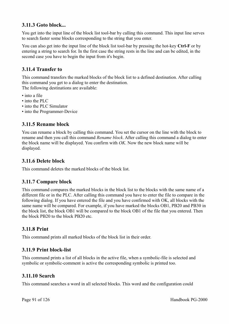
3.11.3 Goto block...
You get into the input line of the block list tool-bar by calling this command. This input line serves to search faster some blocks corresponding to the string that you enter.
You can also get into the input line of the block list tool-bar by pressing the hot-key Ctrl-F or by entering a string to search for. In the first case the string rests in the line and can be edited, in the second case you have to begin the input from it's begin.
3.11.4 Transfer to
This command transfers the marked blocks of the block list to a defined destination. After calling this command you get to a dialog to enter the destination.The following destinations are available:
• into a file• into the PLC• into the PLC Simulator• into the Programmer-Device
3.11.5 Rename block
You can rename a block by calling this command. You set the cursor on the line with the block to rename and then you call this command Rename block. After calling this command a dialog to enterthe block name will be displayed. You confirm with OK. Now the new block name will be displayed.
3.11.6 Delete block
This command deletes the marked blocks of the block list.
3.11.7 Compare block
This command compares the marked blocks in the block list to the blocks with the same name of a different file or in the PLC. After calling this command you have to enter the file to compare in the following dialog. If you have entered the file and you have confirmed with OK, all blocks with the same name will be compared. For example, if you have marked the blocks OB1, PB20 and PB30 in the block list, the block OB1 will be compared to the block OB1 of the file that you entered. Then the block PB20 to the block PB20 etc.
3.11.8 Print
This command prints all marked blocks of the block list in their order.
3.11.9 Print block-list
This command prints a list of all blocks in the active file, when a symbolic-file is selected and symbolic or symbolic-comment is active the corresponding symbolic is printed too.
3.11.10 Search
This command searches a word in all selected blocks. This word and the configuration could
Page 91 of 126 Handbook PG-2000
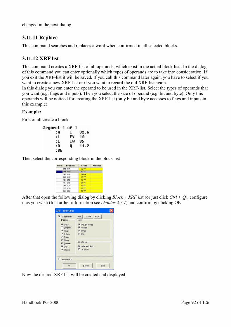
changed in the next dialog.
3.11.11 Replace
This command searches and replaces a word when confirmed in all selected blocks.
3.11.12 XRF list
This command creates a XRF-list of all operands, which exist in the actual block list . In the dialog of this command you can enter optionally which types of operands are to take into consideration. If you exit the XRF-list it will be saved. If you call this command later again, you have to select if youwant to create a new XRF-list or if you want to regard the old XRF-list again.In this dialog you can enter the operand to be used in the XRF-list. Select the types of operands that you want (e.g. flags and inputs). Then you select the size of operand (e.g. bit and byte). Only this operands will be noticed for creating the XRF-list (only bit and byte accesses to flags and inputs in this example).
Example:
First of all create a block
Then select the corresponding block in the block-list
After that open the following dialog by clicking Block XRF list (or just click Ctrl + Q), configure it as you wish (for further information see chapter 2.7.1) and confirm by clicking OK.
Now the desired XRF list will be created and displayed
Handbook PG-2000 Page 92 of 126
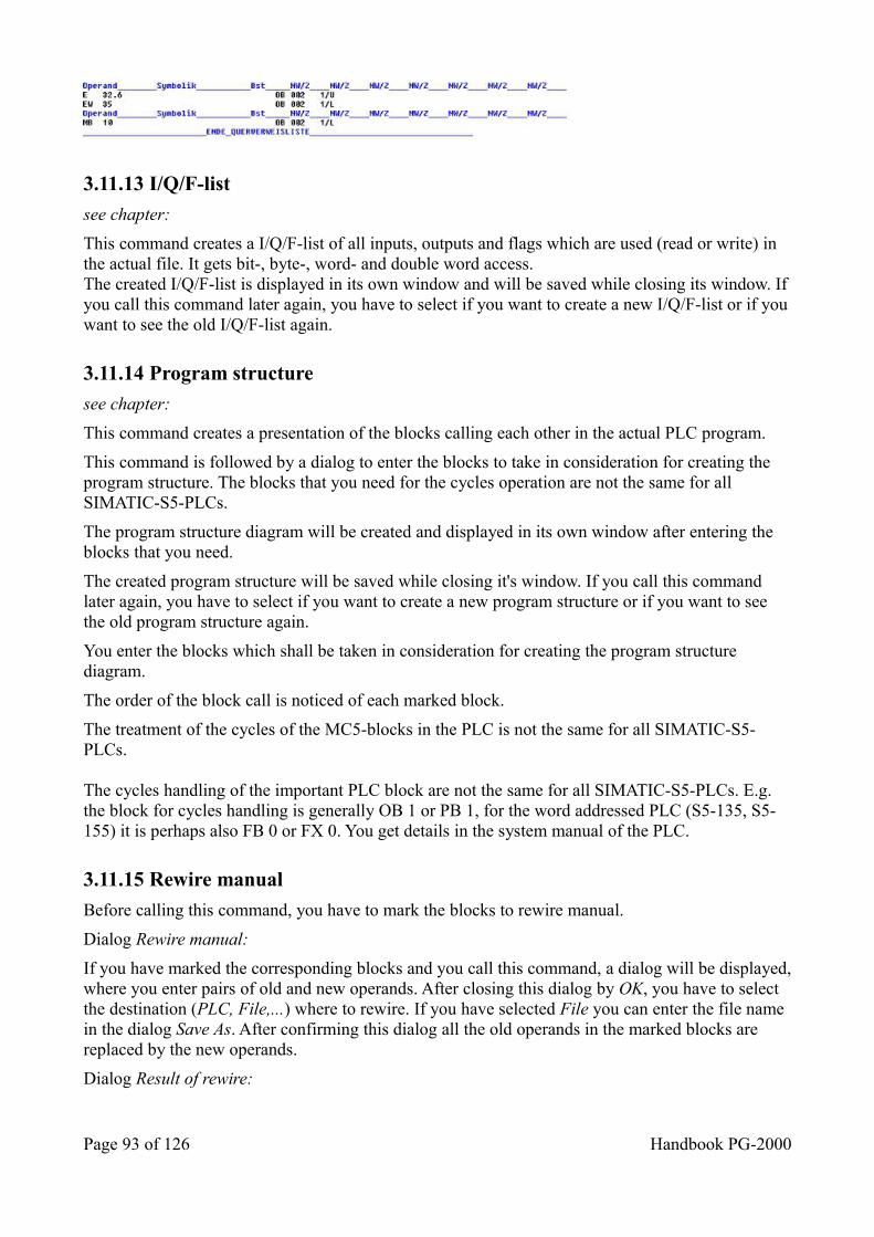
3.11.13 I/Q/F-list
see chapter:
This command creates a I/Q/F-list of all inputs, outputs and flags which are used (read or write) in the actual file. It gets bit-, byte-, word- and double word access.The created I/Q/F-list is displayed in its own window and will be saved while closing its window. Ifyou call this command later again, you have to select if you want to create a new I/Q/F-list or if youwant to see the old I/Q/F-list again.
3.11.14 Program structure
see chapter:
This command creates a presentation of the blocks calling each other in the actual PLC program.
This command is followed by a dialog to enter the blocks to take in consideration for creating the program structure. The blocks that you need for the cycles operation are not the same for all SIMATIC-S5-PLCs.
The program structure diagram will be created and displayed in its own window after entering the blocks that you need.
The created program structure will be saved while closing it's window. If you call this command later again, you have to select if you want to create a new program structure or if you want to see the old program structure again.
You enter the blocks which shall be taken in consideration for creating the program structure diagram.
The order of the block call is noticed of each marked block.
The treatment of the cycles of the MC5-blocks in the PLC is not the same for all SIMATIC-S5-PLCs.
The cycles handling of the important PLC block are not the same for all SIMATIC-S5-PLCs. E.g. the block for cycles handling is generally OB 1 or PB 1, for the word addressed PLC (S5-135, S5-155) it is perhaps also FB 0 or FX 0. You get details in the system manual of the PLC.
3.11.15 Rewire manual
Before calling this command, you have to mark the blocks to rewire manual.
Dialog Rewire manual:
If you have marked the corresponding blocks and you call this command, a dialog will be displayed,where you enter pairs of old and new operands. After closing this dialog by OK, you have to select the destination (PLC, File,...) where to rewire. If you have selected File you can enter the file name in the dialog Save As. After confirming this dialog all the old operands in the marked blocks are replaced by the new operands.
Dialog Result of rewire:
Page 93 of 126 Handbook PG-2000
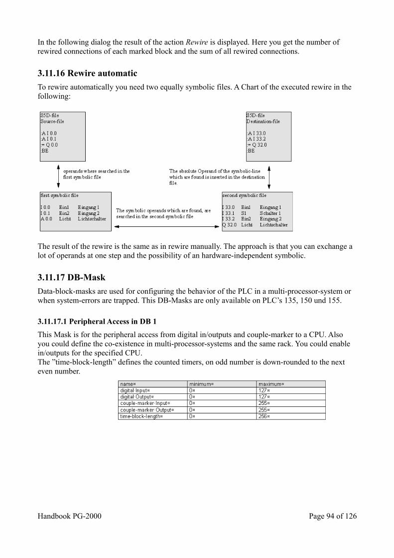
In the following dialog the result of the action Rewire is displayed. Here you get the number of rewired connections of each marked block and the sum of all rewired connections.
3.11.16 Rewire automatic
To rewire automatically you need two equally symbolic files. A Chart of the executed rewire in the following:
The result of the rewire is the same as in rewire manually. The approach is that you can exchange a lot of operands at one step and the possibility of an hardware-independent symbolic.
3.11.17 DB-Mask
Data-block-masks are used for configuring the behavior of the PLC in a multi-processor-system or when system-errors are trapped. This DB-Masks are only available on PLC’s 135, 150 und 155.
3.11.17.1 Peripheral Access in DB 1
This Mask is for the peripheral access from digital in/outputs and couple-marker to a CPU. Also you could define the co-existence in multi-processor-systems and the same rack. You could enable in/outputs for the specified CPU.The ”time-block-length” defines the counted timers, on odd number is down-rounded to the next even number.
Handbook PG-2000 Page 94 of 126
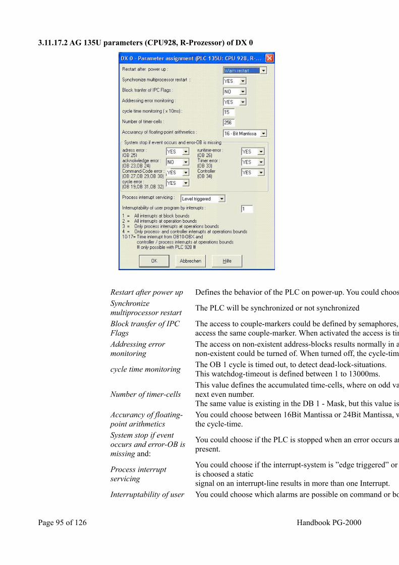
3.11.17.2 AG 135U parameters (CPU928, R-Prozessor) of DX 0
Restart after power up Defines the behavior of the PLC on power-up. You could choose between ”Restart” and ”New-Start”
Synchronize multiprocessor restart
The PLC will be synchronized or not synchronized
Block transfer of IPC Flags
The access to couple-markers could be defined by semaphores, so it is not possible for two CPU’s to access the same couple-marker. When activated the access is timed longer.
Addressing error monitoring
The access on non-existent address-blocks results normally in a PLC-Stop. The testing of this access onnon-existent could be turned of. When turned off, the cycle-time is less than with activated.
cycle time monitoring The OB 1 cycle is timed out, to detect dead-lock-situations.This watchdog-timeout is defined between 1 to 13000ms.
Number of timer-cells This value defines the accumulated time-cells, where on odd values the value is down-rounded to the next even number.The same value is existing in the DB 1 - Mask, but this value is higher priorised than the one in DB 1.
Accurancy of floating-point arithmetics
You could choose between 16Bit Mantissa or 24Bit Mantissa, which have a proportional influence on the cycle-time.
System stop if event occurs and error-OB is missing and:
You could choose if the PLC is stopped when an error occurs and the corresponding error-OB is not present.
Process interrupt servicing
You could choose if the interrupt-system is ”edge triggered” or ”state triggered”. When state triggered is choosed a staticsignal on an interrupt-line results in more than one Interrupt.
Interruptability of user You could choose which alarms are possible on command or borders
Page 95 of 126 Handbook PG-2000
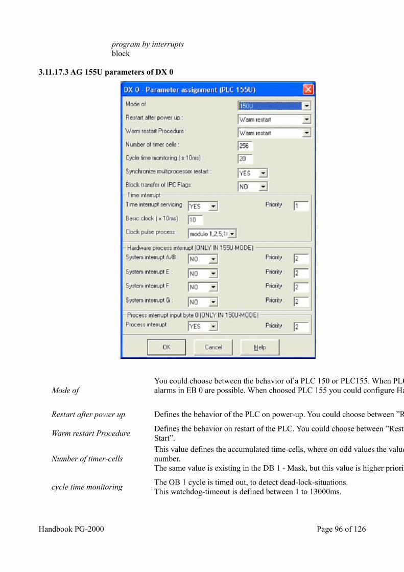
program by interrupts block
3.11.17.3 AG 155U parameters of DX 0
Mode of You could choose between the behavior of a PLC 150 or PLC155. When PLC 150 is choosed extended process-alarms in EB 0 are possible. When choosed PLC 155 you could configure Hardware-process-alarms
Restart after power up Defines the behavior of the PLC on power-up. You could choose between ”Restart” and ”New-Start”
Warm restart Procedure Defines the behavior on restart of the PLC. You could choose between ”Restart” (the default) and ”remanent New Start”.
Number of timer-cells This value defines the accumulated time-cells, where on odd values the value is down-rounded to the next even number.The same value is existing in the DB 1 - Mask, but this value is higher priorised than the one in DB 1.
cycle time monitoring The OB 1 cycle is timed out, to detect dead-lock-situations.This watchdog-timeout is defined between 1 to 13000ms.
Handbook PG-2000 Page 96 of 126
Synchronize multiprocessor restart
The PLC will be synchronized or not synchronized
Block transfer of IPC Flags The access to couple-markers could be defined by semaphores, so it is not possible for two CPU’s to access the same couple-marker. When activated the access is timed longer.
Time interrupt servicing Hier wird eingestellt ob überhaupt Zeitalarme erzeugt werden.
Priority Defines the Priority from 1 to 5.
Basic clock Defines the timing of the alarms, default is 10ms.
Clock pulse process Defines the clock for the alarm-timer. You could choosebetween 1,2,5,10 or 1,2,4,8.
System interrupt A/B Defines if the system-interrupt A,B,C and D are processed and which priority is used.
System interrupt E Defines if the system-interrupt E are processed and which priority is used.
System interrupt F Defines if the system-interrupt F are processed and which priority is used.
System interrupt G Defines if the system-interrupt G are processed and which priority is used.
Process interrupt Defines if the hardware-interrupts are processed and which priority is used.
3.11.18 AG95F Diagnosis
In this menu you could let analyze the diagnostic data-block of the AG95F. It is always analyzed theDB 254 of the active document, whether the document is a file or a PLC. The following dialogs are for disposal:
______________________
MessagesOnBoardSignalgroupExternalL1______________________
3.11.18.1 Messages
In DB 254 the data words 1, 34, 37, 62 as well as 64 to 191 are analyzed and represented in the following dialog:
System - ID the system – ID is displayed here, which was taken over fromthe DB1
Position the error locations are displayed which are detected so far
Page 97 of 126 Handbook PG-2000
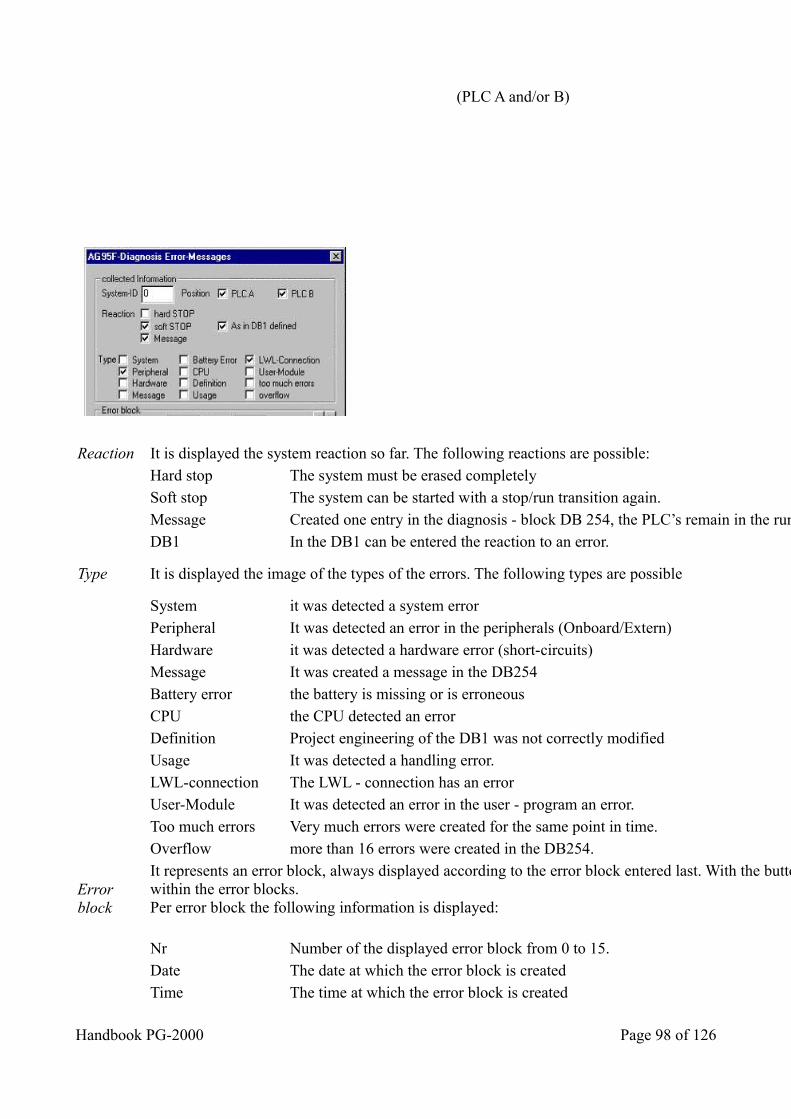
(PLC A and/or B)
Reaction It is displayed the system reaction so far. The following reactions are possible: Hard stop The system must be erased completely Soft stop The system can be started with a stop/run transition again. Message Created one entry in the diagnosis - block DB 254, the PLC’s remain in the run State. DB1 In the DB1 can be entered the reaction to an error.
Type It is displayed the image of the types of the errors. The following types are possible
System it was detected a system error Peripheral It was detected an error in the peripherals (Onboard/Extern) Hardware it was detected a hardware error (short-circuits) Message It was created a message in the DB254 Battery error the battery is missing or is erroneous CPU the CPU detected an error Definition Project engineering of the DB1 was not correctly modified Usage It was detected a handling error. LWL-connection The LWL - connection has an error User-Module It was detected an error in the user - program an error. Too much errors Very much errors were created for the same point in time. Overflow more than 16 errors were created in the DB254.
Error block
It represents an error block, always displayed according to the error block entered last. With the buttons " < " and " > " you could navigate within the error blocks.Per error block the following information is displayed:
Nr Number of the displayed error block from 0 to 15. Date The date at which the error block is created Time The time at which the error block is created
Handbook PG-2000 Page 98 of 126
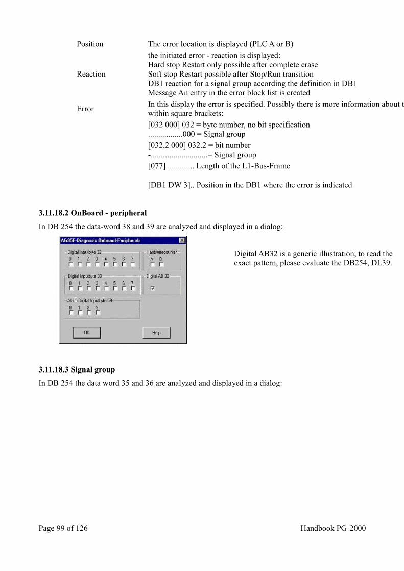
Position The error location is displayed (PLC A or B)
Reaction
the initiated error - reaction is displayed:Hard stop Restart only possible after complete eraseSoft stop Restart possible after Stop/Run transitionDB1 reaction for a signal group according the definition in DB1Message An entry in the error block list is created
Error In this display the error is specified. Possibly there is more information about the error which then will be display within square brackets:
[032 000] 032 = byte number, no bit specification.................000 = Signal group
[032.2 000] 032.2 = bit number-............................= Signal group
[077].............. Length of the L1-Bus-Frame
[DB1 DW 3].. Position in the DB1 where the error is indicated
3.11.18.2 OnBoard - peripheral
In DB 254 the data-word 38 and 39 are analyzed and displayed in a dialog:
Digital AB32 is a generic illustration, to read the exact pattern, please evaluate the DB254, DL39.
3.11.18.3 Signal group
In DB 254 the data word 35 and 36 are analyzed and displayed in a dialog:
Page 99 of 126 Handbook PG-2000
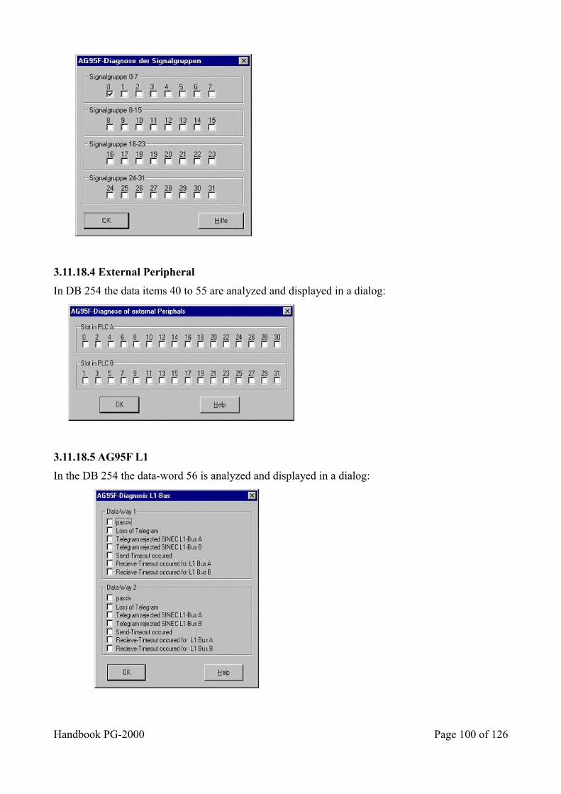
3.11.18.4 External Peripheral
In DB 254 the data items 40 to 55 are analyzed and displayed in a dialog:
3.11.18.5 AG95F L1
In the DB 254 the data-word 56 is analyzed and displayed in a dialog:
Handbook PG-2000 Page 100 of 126
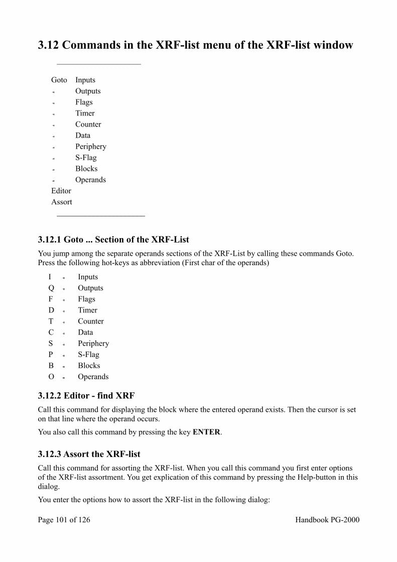
3.12 Commands in the XRF-list menu of the XRF-list window _____________________
Goto Inputs Outputs Flags Timer Counter Data Periphery S-Flag Blocks Operands Editor Assort
______________________
3.12.1 Goto ... Section of the XRF-List
You jump among the separate operands sections of the XRF-List by calling these commands Goto. Press the following hot-keys as abbreviation (First char of the operands)
I Inputs Q Outputs F Flags D Timer T Counter C Data S Periphery P S-Flag B Blocks O Operands
3.12.2 Editor - find XRF
Call this command for displaying the block where the entered operand exists. Then the cursor is set on that line where the operand occurs.
You also call this command by pressing the key ENTER.
3.12.3 Assort the XRF-list
Call this command for assorting the XRF-list. When you call this command you first enter options of the XRF-list assortment. You get explication of this command by pressing the Help-button in thisdialog.
You enter the options how to assort the XRF-list in the following dialog:
Page 101 of 126 Handbook PG-2000
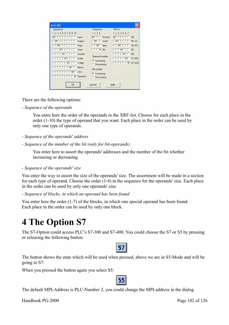
There are the following options:
- Sequence of the operands
You enter here the order of the operands in the XRF-list. Choose for each place in the order (1-10) the type of operand that you want. Each place in the order can be used by only one type of operands.
- Sequence of the operands' address
- Sequence of the number of the bit (only for bit-operands)
You enter here to assort the operands' addresses and the number of the bit whether increasing or decreasing.
- Sequence of the operands' size
You enter the way to assort the size of the operands' size. The assortment will be made in a section for each type of operand. Choose the order (1-4) in the sequence for the operands' size. Each place in the order can be used by only one operands' size.
- Sequence of blocks, in which an operand has been found
You enter here the order (1-7) of the blocks, in which one special operand has been found.Each place in the order can be used by only one block.
4 The Option S7 The S7-Option could access PLC’s S7-300 and S7-400. You could choose the S7 or S5 by pressing or releasing the following button:
The button shows the state which will be used when pressed, above we are in S5-Mode and will be going to S7:
When you pressed the button again you select S5:
The default MPI-Address is PLC-Number 2, you could change the MPI-address in the dialog
Handbook PG-2000 Page 102 of 126
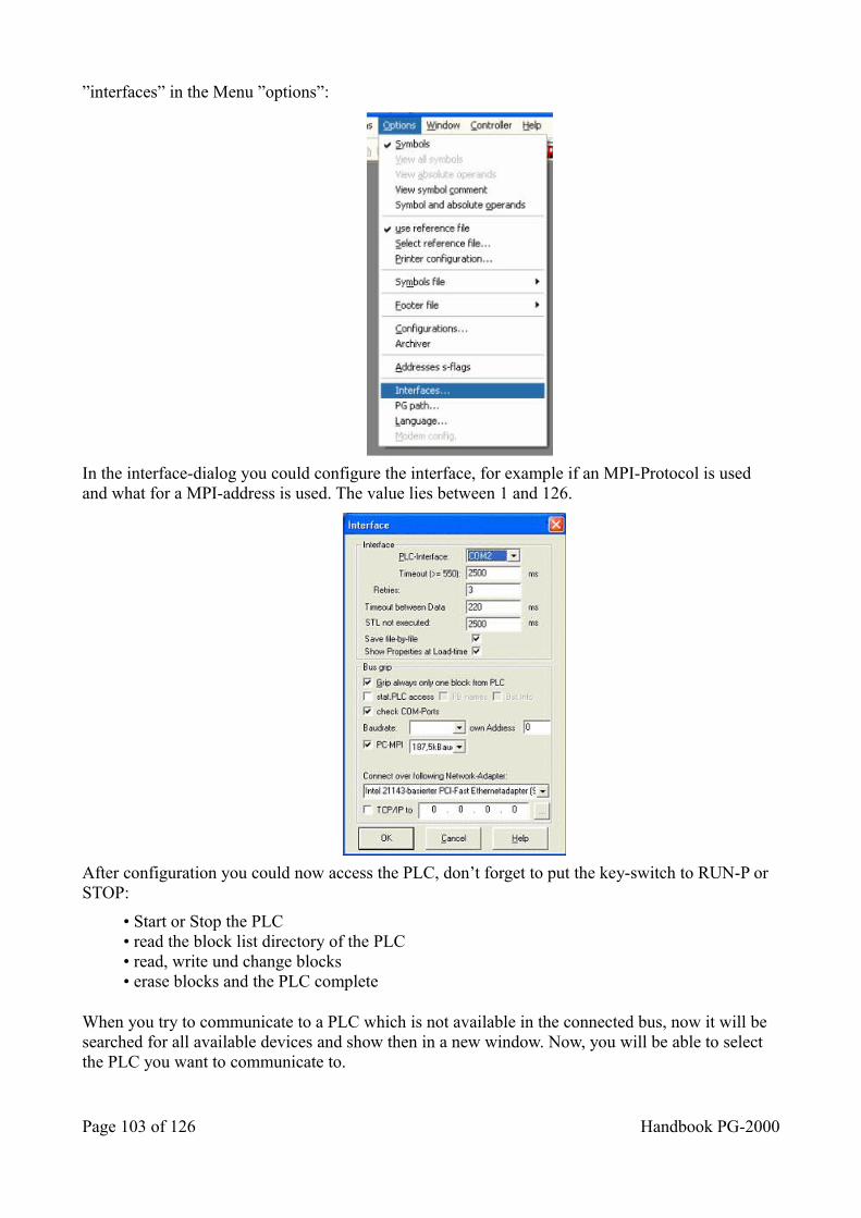
”interfaces” in the Menu ”options”:
In the interface-dialog you could configure the interface, for example if an MPI-Protocol is used and what for a MPI-address is used. The value lies between 1 and 126.
After configuration you could now access the PLC, don’t forget to put the key-switch to RUN-P or STOP:
• Start or Stop the PLC• read the block list directory of the PLC• read, write und change blocks• erase blocks and the PLC complete
When you try to communicate to a PLC which is not available in the connected bus, now it will be searched for all available devices and show then in a new window. Now, you will be able to select the PLC you want to communicate to.
Page 103 of 126 Handbook PG-2000
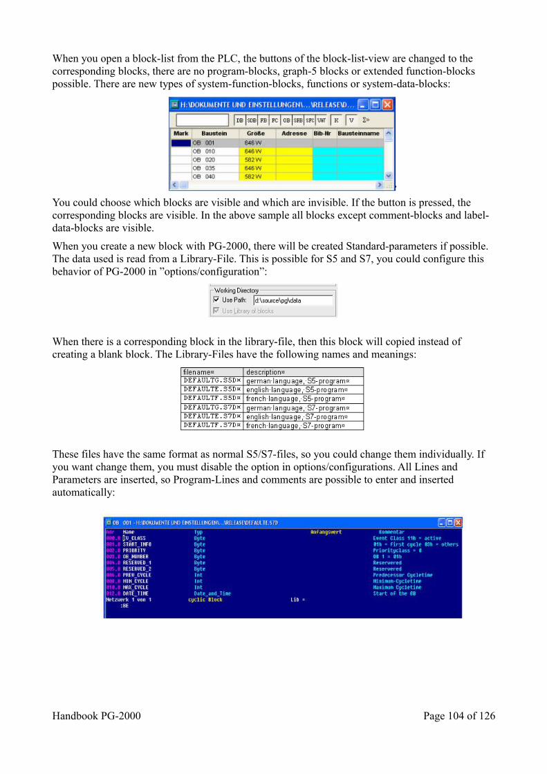
When you open a block-list from the PLC, the buttons of the block-list-view are changed to the corresponding blocks, there are no program-blocks, graph-5 blocks or extended function-blocks possible. There are new types of system-function-blocks, functions or system-data-blocks:
You could choose which blocks are visible and which are invisible. If the button is pressed, the corresponding blocks are visible. In the above sample all blocks except comment-blocks and label-data-blocks are visible.
When you create a new block with PG-2000, there will be created Standard-parameters if possible. The data used is read from a Library-File. This is possible for S5 and S7, you could configure this behavior of PG-2000 in ”options/configuration”:
When there is a corresponding block in the library-file, then this block will copied instead of creating a blank block. The Library-Files have the following names and meanings:
These files have the same format as normal S5/S7-files, so you could change them individually. If you want change them, you must disable the option in options/configurations. All Lines and Parameters are inserted, so Program-Lines and comments are possible to enter and inserted automatically:
Handbook PG-2000 Page 104 of 126
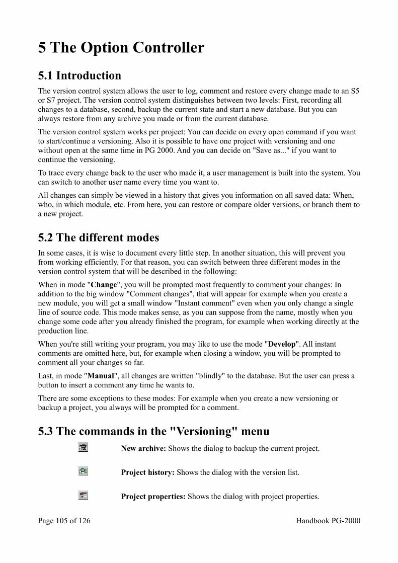
5 The Option Controller
5.1 Introduction The version control system allows the user to log, comment and restore every change made to an S5or S7 project. The version control system distinguishes between two levels: First, recording all changes to a database, second, backup the current state and start a new database. But you can always restore from any archive you made or from the current database.
The version control system works per project: You can decide on every open command if you want to start/continue a versioning. Also it is possible to have one project with versioning and one without open at the same time in PG 2000. And you can decide on "Save as..." if you want to continue the versioning.
To trace every change back to the user who made it, a user management is built into the system. Youcan switch to another user name every time you want to.
All changes can simply be viewed in a history that gives you information on all saved data: When, who, in which module, etc. From here, you can restore or compare older versions, or branch them toa new project.
5.2 The different modes In some cases, it is wise to document every little step. In another situation, this will prevent you from working efficiently. For that reason, you can switch between three different modes in the version control system that will be described in the following:
When in mode "Change", you will be prompted most frequently to comment your changes: In addition to the big window "Comment changes", that will appear for example when you create a new module, you will get a small window "Instant comment" even when you only change a single line of source code. This mode makes sense, as you can suppose from the name, mostly when you change some code after you already finished the program, for example when working directly at theproduction line.
When you're still writing your program, you may like to use the mode "Develop". All instant comments are omitted here, but, for example when closing a window, you will be prompted to comment all your changes so far.
Last, in mode "Manual", all changes are written "blindly" to the database. But the user can press a button to insert a comment any time he wants to.
There are some exceptions to these modes: For example when you create a new versioning or backup a project, you always will be prompted for a comment.
5.3 The commands in the "Versioning" menu New archive: Shows the dialog to backup the current project.
Project history: Shows the dialog with the version list.
Project properties: Shows the dialog with project properties.
Page 105 of 126 Handbook PG-2000
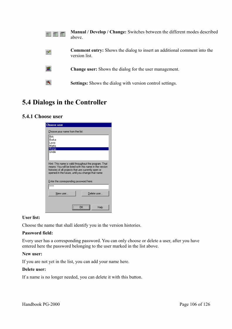
Manual / Develop / Change: Switches between the different modes described above.
Comment entry: Shows the dialog to insert an additional comment into the version list.
Change user: Shows the dialog for the user management.
Settings: Shows the dialog with version control settings.
5.4 Dialogs in the Controller
5.4.1 Choose user
User list:
Choose the name that shall identify you in the version histories.
Password field:
Every user has a corresponding password. You can only choose or delete a user, after you have entered here the password belonging to the user marked in the list above.
New user:
If you are not yet in the list, you can add your name here.
Delete user:
If a name is no longer needed, you can delete it with this button.
Handbook PG-2000 Page 106 of 126
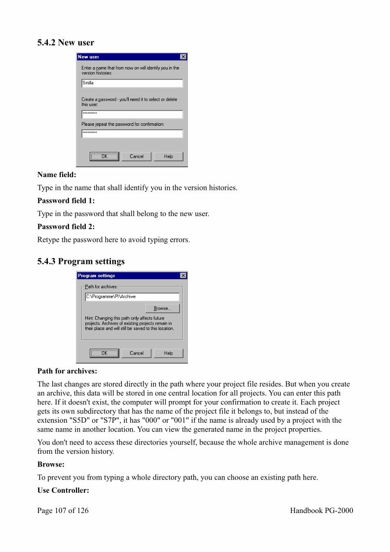
5.4.2 New user
Name field:
Type in the name that shall identify you in the version histories.
Password field 1:
Type in the password that shall belong to the new user.
Password field 2:
Retype the password here to avoid typing errors.
5.4.3 Program settings
Path for archives:
The last changes are stored directly in the path where your project file resides. But when you create an archive, this data will be stored in one central location for all projects. You can enter this path here. If it doesn't exist, the computer will prompt for your confirmation to create it. Each project gets its own subdirectory that has the name of the project file it belongs to, but instead of the extension "S5D" or "S7P", it has "000" or "001" if the name is already used by a project with the same name in another location. You can view the generated name in the project properties.
You don't need to access these directories yourself, because the whole archive management is done from the version history.
Browse:
To prevent you from typing a whole directory path, you can choose an existing path here.
Use Controller:
Page 107 of 126 Handbook PG-2000
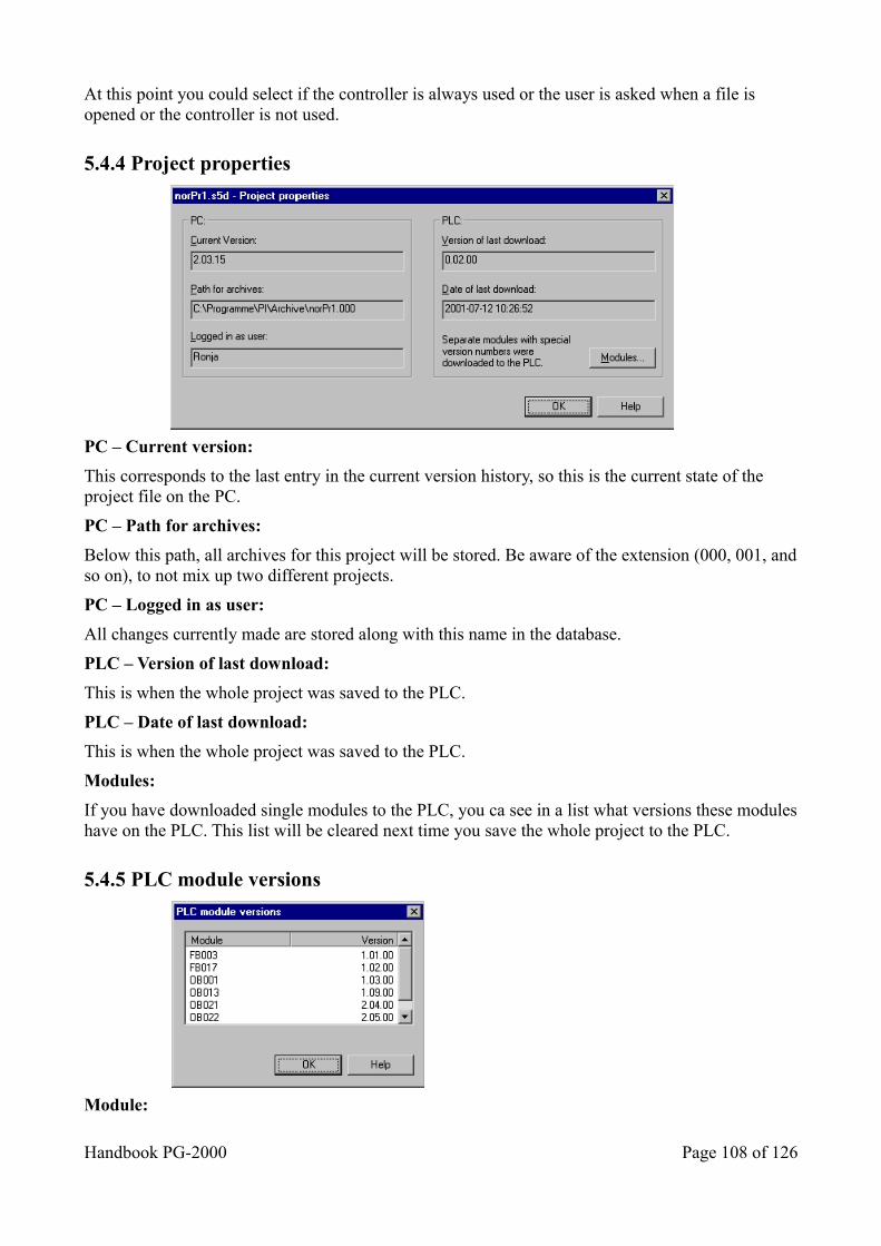
At this point you could select if the controller is always used or the user is asked when a file is opened or the controller is not used.
5.4.4 Project properties
PC – Current version:
This corresponds to the last entry in the current version history, so this is the current state of the project file on the PC.
PC – Path for archives:
Below this path, all archives for this project will be stored. Be aware of the extension (000, 001, andso on), to not mix up two different projects.
PC – Logged in as user:
All changes currently made are stored along with this name in the database.
PLC – Version of last download:
This is when the whole project was saved to the PLC.
PLC – Date of last download:
This is when the whole project was saved to the PLC.
Modules:
If you have downloaded single modules to the PLC, you ca see in a list what versions these moduleshave on the PLC. This list will be cleared next time you save the whole project to the PLC.
5.4.5 PLC module versions
Module:
Handbook PG-2000 Page 108 of 126
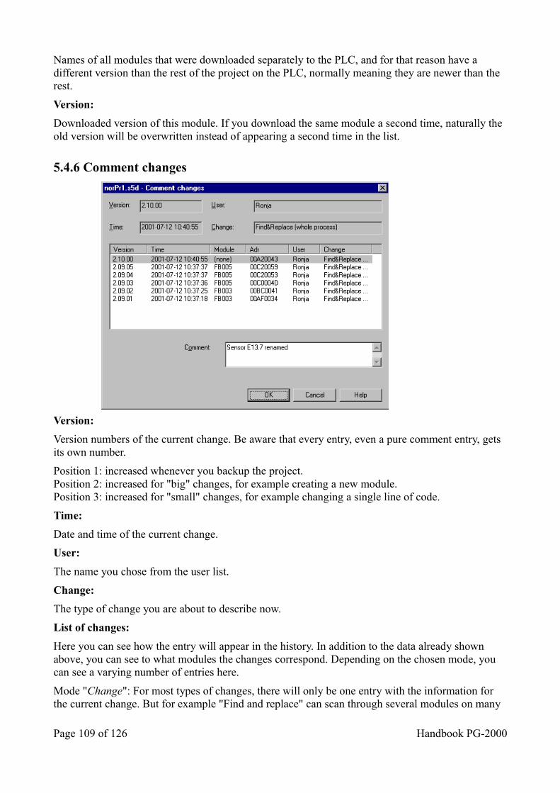
Names of all modules that were downloaded separately to the PLC, and for that reason have a different version than the rest of the project on the PLC, normally meaning they are newer than the rest.
Version:
Downloaded version of this module. If you download the same module a second time, naturally the old version will be overwritten instead of appearing a second time in the list.
5.4.6 Comment changes
Version:
Version numbers of the current change. Be aware that every entry, even a pure comment entry, gets its own number.
Position 1: increased whenever you backup the project.Position 2: increased for "big" changes, for example creating a new module.Position 3: increased for "small" changes, for example changing a single line of code.
Time:
Date and time of the current change.
User:
The name you chose from the user list.
Change:
The type of change you are about to describe now.
List of changes:
Here you can see how the entry will appear in the history. In addition to the data already shown above, you can see to what modules the changes correspond. Depending on the chosen mode, you can see a varying number of entries here.
Mode "Change": For most types of changes, there will only be one entry with the information for the current change. But for example "Find and replace" can scan through several modules on many
Page 109 of 126 Handbook PG-2000
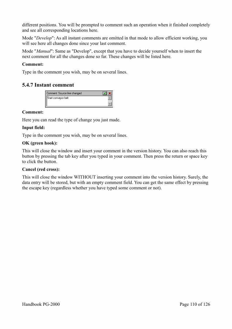
different positions. You will be prompted to comment such an operation when it finished completelyand see all corresponding locations here.
Mode "Develop": As all instant comments are omitted in that mode to allow efficient working, you will see here all changes done since your last comment.
Mode "Manual": Same as "Develop", except that you have to decide yourself when to insert the next comment for all the changes done so far. These changes will be listed here.
Comment:
Type in the comment you wish, may be on several lines.
5.4.7 Instant comment
Comment:
Here you can read the type of change you just made.
Input field:
Type in the comment you wish, may be on several lines.
OK (green hook):
This will close the window and insert your comment in the version history. You can also reach this button by pressing the tab key after you typed in your comment. Then press the return or space key to click the button.
Cancel (red cross):
This will close the window WITHOUT inserting your comment into the version history. Surely, the data entry will be stored, but with an empty comment field. You can get the same effect by pressing the escape key (regardless whether you have typed some comment or not).
Handbook PG-2000 Page 110 of 126
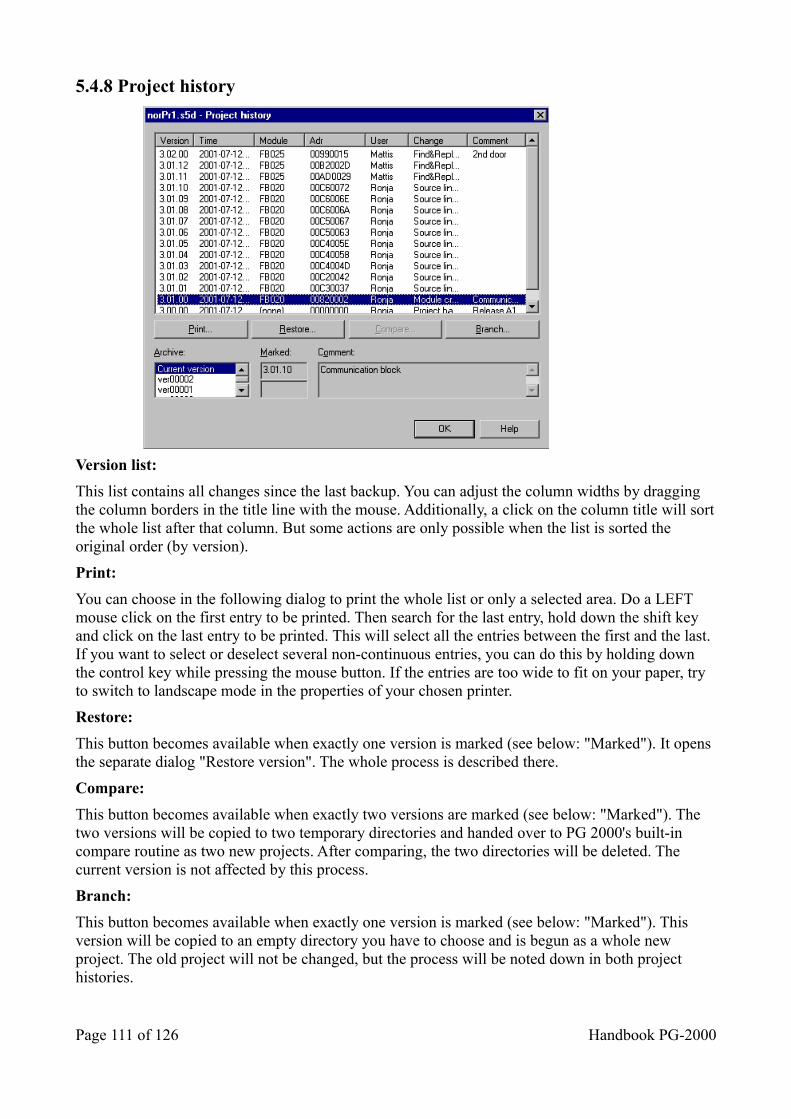
5.4.8 Project history
Version list:
This list contains all changes since the last backup. You can adjust the column widths by dragging the column borders in the title line with the mouse. Additionally, a click on the column title will sortthe whole list after that column. But some actions are only possible when the list is sorted the original order (by version).
Print:
You can choose in the following dialog to print the whole list or only a selected area. Do a LEFT mouse click on the first entry to be printed. Then search for the last entry, hold down the shift key and click on the last entry to be printed. This will select all the entries between the first and the last. If you want to select or deselect several non-continuous entries, you can do this by holding down the control key while pressing the mouse button. If the entries are too wide to fit on your paper, try to switch to landscape mode in the properties of your chosen printer.
Restore:
This button becomes available when exactly one version is marked (see below: "Marked"). It opens the separate dialog "Restore version". The whole process is described there.
Compare:
This button becomes available when exactly two versions are marked (see below: "Marked"). The two versions will be copied to two temporary directories and handed over to PG 2000's built-in compare routine as two new projects. After comparing, the two directories will be deleted. The current version is not affected by this process.
Branch:
This button becomes available when exactly one version is marked (see below: "Marked"). This version will be copied to an empty directory you have to choose and is begun as a whole new project. The old project will not be changed, but the process will be noted down in both project histories.
Page 111 of 126 Handbook PG-2000
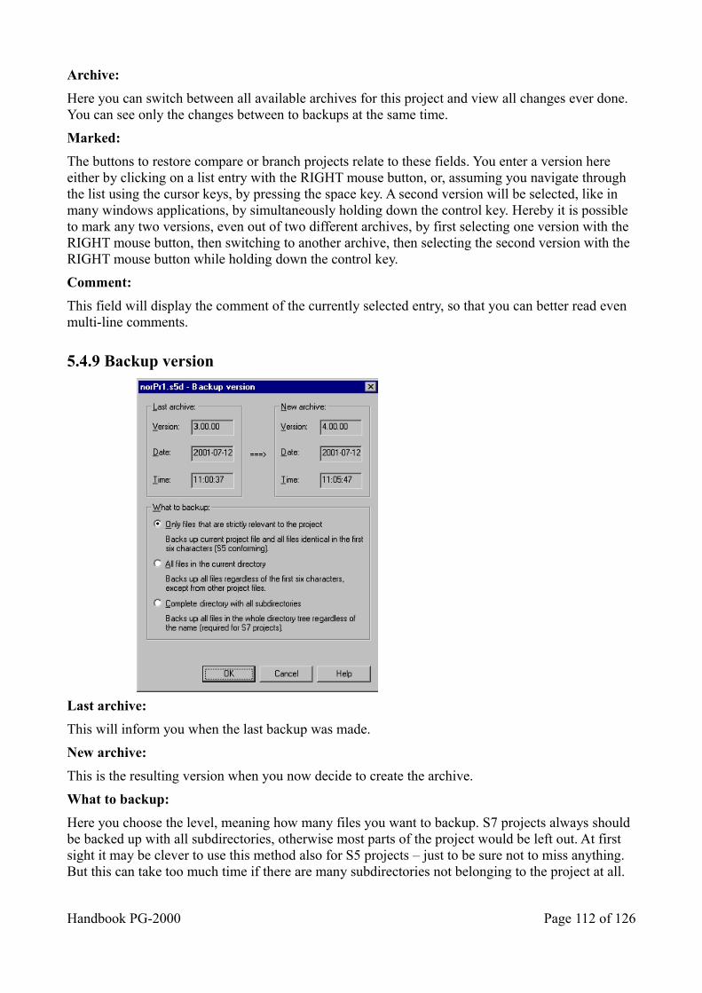
Archive:
Here you can switch between all available archives for this project and view all changes ever done. You can see only the changes between to backups at the same time.
Marked:
The buttons to restore compare or branch projects relate to these fields. You enter a version here either by clicking on a list entry with the RIGHT mouse button, or, assuming you navigate through the list using the cursor keys, by pressing the space key. A second version will be selected, like in many windows applications, by simultaneously holding down the control key. Hereby it is possible to mark any two versions, even out of two different archives, by first selecting one version with the RIGHT mouse button, then switching to another archive, then selecting the second version with the RIGHT mouse button while holding down the control key.
Comment:
This field will display the comment of the currently selected entry, so that you can better read even multi-line comments.
5.4.9 Backup version
Last archive:
This will inform you when the last backup was made.
New archive:
This is the resulting version when you now decide to create the archive.
What to backup:
Here you choose the level, meaning how many files you want to backup. S7 projects always should be backed up with all subdirectories, otherwise most parts of the project would be left out. At first sight it may be clever to use this method also for S5 projects – just to be sure not to miss anything. But this can take too much time if there are many subdirectories not belonging to the project at all.
Handbook PG-2000 Page 112 of 126
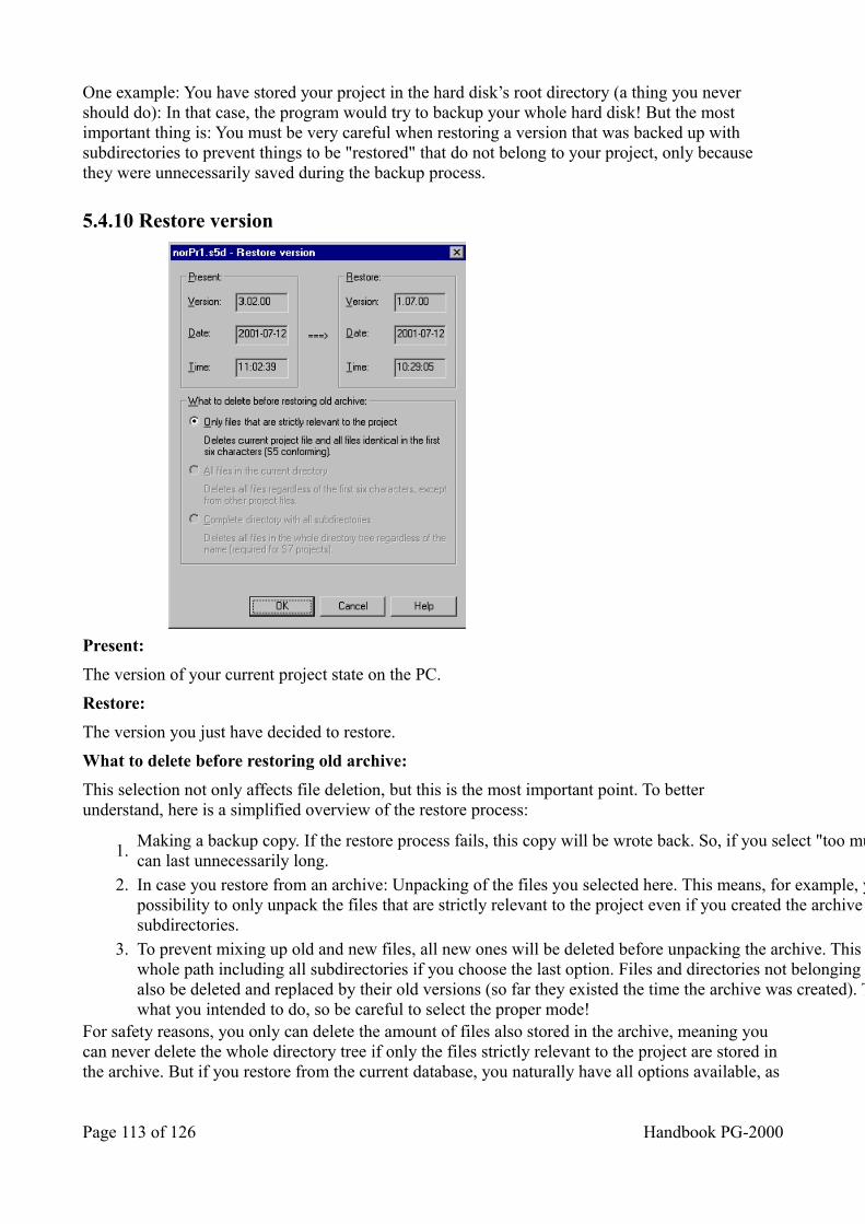
One example: You have stored your project in the hard disk’s root directory (a thing you never should do): In that case, the program would try to backup your whole hard disk! But the most important thing is: You must be very careful when restoring a version that was backed up with subdirectories to prevent things to be "restored" that do not belong to your project, only because they were unnecessarily saved during the backup process.
5.4.10 Restore version
Present:
The version of your current project state on the PC.
Restore:
The version you just have decided to restore.
What to delete before restoring old archive:
This selection not only affects file deletion, but this is the most important point. To better understand, here is a simplified overview of the restore process:
1.Making a backup copy. If the restore process fails, this copy will be wrote back. So, if you select "too much", this process can last unnecessarily long.
2. In case you restore from an archive: Unpacking of the files you selected here. This means, for example, you have the possibility to only unpack the files that are strictly relevant to the project even if you created the archive including all subdirectories.
3. To prevent mixing up old and new files, all new ones will be deleted before unpacking the archive. This means: The whole path including all subdirectories if you choose the last option. Files and directories not belonging to the project willalso be deleted and replaced by their old versions (so far they existed the time the archive was created). This is surely not what you intended to do, so be careful to select the proper mode!
For safety reasons, you only can delete the amount of files also stored in the archive, meaning you can never delete the whole directory tree if only the files strictly relevant to the project are stored in the archive. But if you restore from the current database, you naturally have all options available, as
Page 113 of 126 Handbook PG-2000
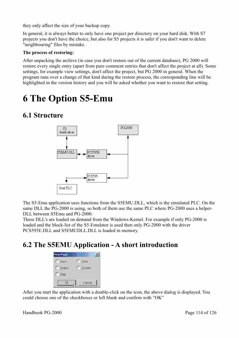
they only affect the size of your backup copy.
In general, it is always better to only have one project per directory on your hard disk. With S7 projects you don't have the choice, but also for S5 projects it is safer if you don't want to delete "neighbouring" files by mistake.
The process of restoring:
After unpacking the archive (in case you don't restore out of the current database), PG 2000 will restore every single entry (apart from pure comment entries that don't affect the project at all). Somesettings, for example view settings, don't affect the project, but PG 2000 in general. When the program runs over a change of that kind during the restore process, the corresponding line will be highlighted in the version history and you will be asked whether you want to restore that setting.
6 The Option S5-Emu
6.1 Structure
The S5-Emu application uses functions from the S5EMU.DLL, which is the simulated PLC. On the same DLL the PG-2000 is using, so both of them use the same PLC where PG-2000 uses a helper-DLL between S5Emu and PG-2000.These DLL’s are loaded on demand from the Windows-Kernel. For example if only PG-2000 is loaded and the block-list of the S5-Emulator is used then only PG-2000 with the driver PCS595E.DLL and S5EMUDLL.DLL is loaded in memory.
6.2 The S5EMU Application - A short introduction
After you start the application with a double-click on the icon, the above dialog is displayed. You could choose one of the checkboxes or left blank and confirm with ”OK”
Handbook PG-2000 Page 114 of 126
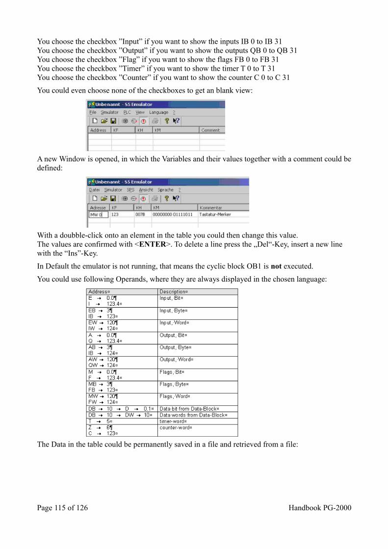
You choose the checkbox ”Input” if you want to show the inputs IB 0 to IB 31You choose the checkbox ”Output” if you want to show the outputs QB 0 to QB 31You choose the checkbox ”Flag” if you want to show the flags FB 0 to FB 31You choose the checkbox ”Timer” if you want to show the timer T 0 to T 31You choose the checkbox ”Counter” if you want to show the counter C 0 to C 31
You could even choose none of the checkboxes to get an blank view:
A new Window is opened, in which the Variables and their values together with a comment could bedefined:
With a doubble-click onto an element in the table you could then change this value.The values are confirmed with <ENTER>. To delete a line press the „Del“-Key, insert a new line with the “Ins”-Key.
In Default the emulator is not running, that means the cyclic block OB1 is not executed.
You could use following Operands, where they are always displayed in the chosen language:
The Data in the table could be permanently saved in a file and retrieved from a file:
Page 115 of 126 Handbook PG-2000
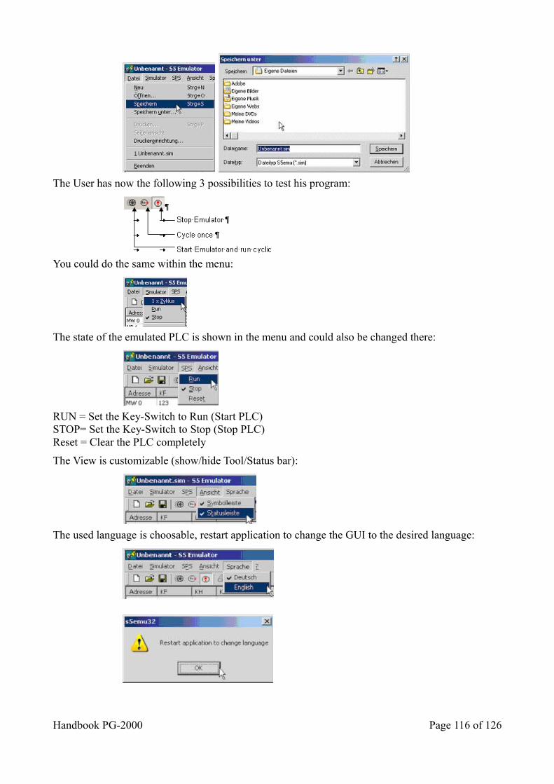
The User has now the following 3 possibilities to test his program:
You could do the same within the menu:
The state of the emulated PLC is shown in the menu and could also be changed there:
RUN = Set the Key-Switch to Run (Start PLC)STOP= Set the Key-Switch to Stop (Stop PLC)Reset = Clear the PLC completely
The View is customizable (show/hide Tool/Status bar):
The used language is choosable, restart application to change the GUI to the desired language:
Handbook PG-2000 Page 116 of 126
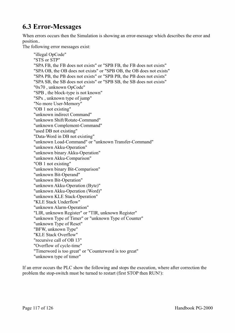
6.3 Error-Messages When errors occurs then the Simulation is showing an error-message which describes the error and position..The following error messages exist:
"illegal OpCode""STS or STP""SPA FB, the FB does not exists" or "SPB FB, the FB does not exists""SPA OB, the OB does not exists" or "SPB OB, the OB does not exists""SPA PB, the PB does not exists" or "SPB PB, the PB does not exists""SPA SB, the SB does not exists" or "SPB SB, the SB does not exists""0x70 , unknown OpCode""SPB , the block-type is not known""SPx , unknown type of jump""No more User-Memory""OB 1 not existing""unknown indirect Command""unknown Shift/Rotate-Command""unknown Complement-Command""used DB not existing""Data-Word in DB not existing""unknown Load-Command" or "unknown Transfer-Command""unknown Akku-Operation""unknown binary Akku-Operation""unknown Akku-Comparison""OB 1 not existing""unknown binary Bit-Comparison""unknown Bit-Operand""unknown Bit-Operation""unknown Akku-Operation (Byte)""unknown Akku-Operation (Word)""unknown KLE Stack-Operation""KLE Stack Underflow""unknown Alarm-Operation""LIR, unknown Register" or "TIR, unknown Register""unknown Type of Timer" or "unknown Type of Counter""unknown Type of Reset""BFW, unknown Type""KLE Stack Overflow""recursive call of OB 13""Overflow of cycle-time""Timerword is too great" or "Counterword is too great""unknown type of timer"
If an error occurs the PLC show the following and stops the execution, where after correction the problem the stop-switch must be turned to restart (first STOP then RUN!):
Page 117 of 126 Handbook PG-2000
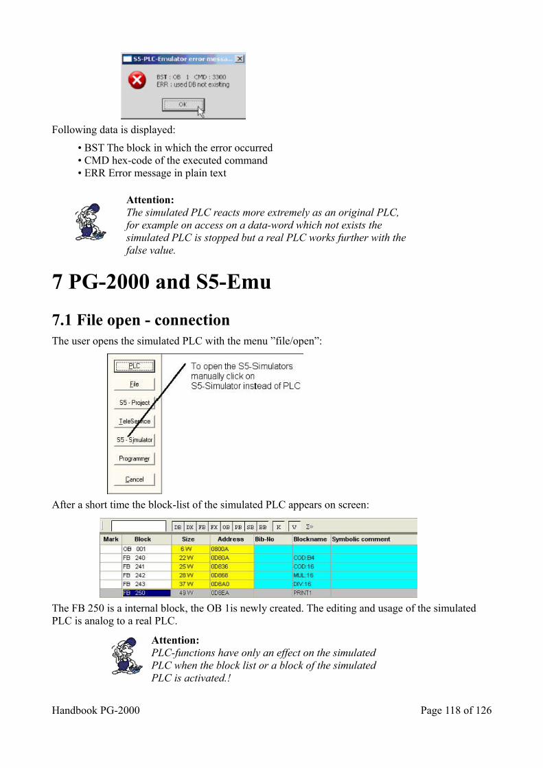
Following data is displayed:
• BST The block in which the error occurred• CMD hex-code of the executed command• ERR Error message in plain text
Attention:The simulated PLC reacts more extremely as an original PLC, for example on access on a data-word which not exists the simulated PLC is stopped but a real PLC works further with the false value.
7 PG-2000 and S5-Emu
7.1 File open - connection The user opens the simulated PLC with the menu ”file/open”:
After a short time the block-list of the simulated PLC appears on screen:
The FB 250 is a internal block, the OB 1is newly created. The editing and usage of the simulated PLC is analog to a real PLC.
Attention:PLC-functions have only an effect on the simulatedPLC when the block list or a block of the simulatedPLC is activated.!
Handbook PG-2000 Page 118 of 126
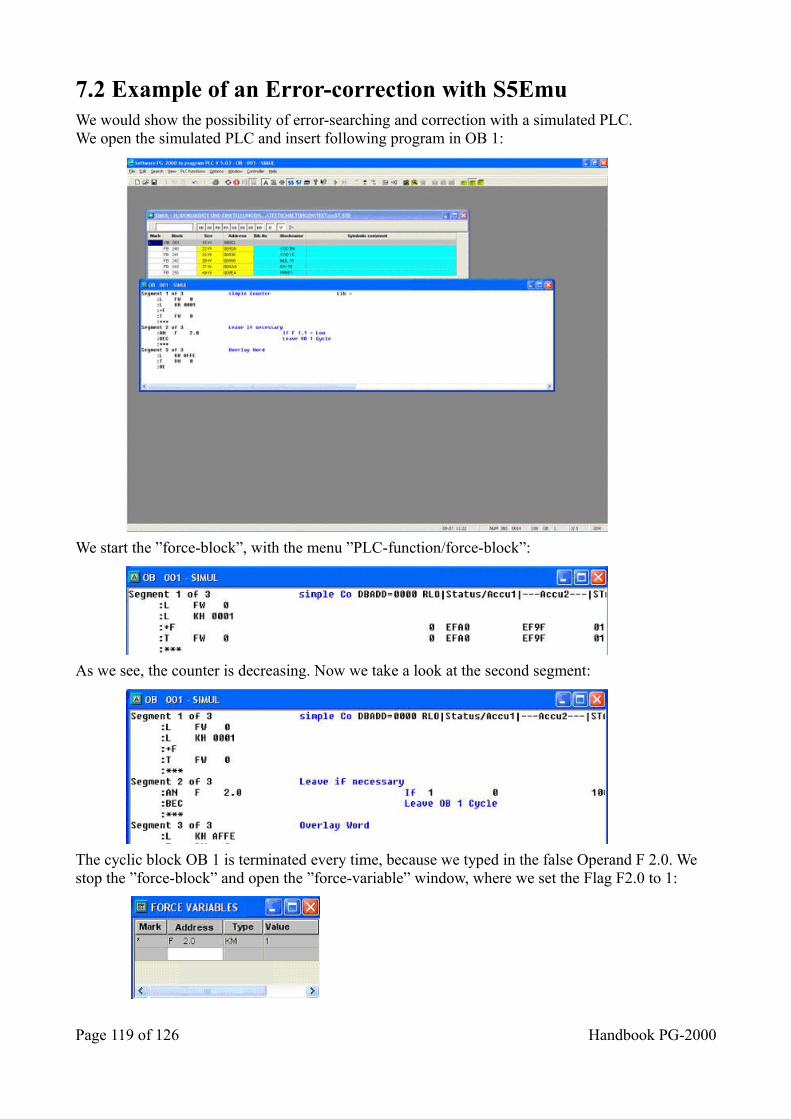
7.2 Example of an Error-correction with S5Emu We would show the possibility of error-searching and correction with a simulated PLC.We open the simulated PLC and insert following program in OB 1:
We start the ”force-block”, with the menu ”PLC-function/force-block”:
As we see, the counter is decreasing. Now we take a look at the second segment:
The cyclic block OB 1 is terminated every time, because we typed in the false Operand F 2.0. We stop the ”force-block” and open the ”force-variable” window, where we set the Flag F2.0 to 1:
Page 119 of 126 Handbook PG-2000

Immediately after transferring the 1 to the PLC we get an error, that the Data-block is missing, we have forgotten to generate and call the data-block. So now we create a new data-block 10 with a view data words. Also we insert before the first access to the data-word a ”C DB 10”. After restarting the PLC the data-word is changing.We now start the application ”S5 Emu” und inserted some data to view:
When you change the bit F 2.0 with the mouse on the button ”0” the Data-word 0 is changed to ”AFFE”.
Finally an screen-shot of an simulated error-search in one PC with an simulated PLC and the programming system simultaneously working:
As you see, it is possible to use both programs together.
Handbook PG-2000 Page 120 of 126
8 Help
8.1 Help for Comparison Choose the type of the comparison by clicking the corresponding variable and enter the input and output parameters.
The following types of comparison are available:
• != ...compare to equal to• >< ..compare to not equal to• < ....compare to less than• <= ..compare to less than or equal to• > ....compare to greater than• >= ..compare to greater than or equal to
See also: The following operands are available.
Symbol and Comment are to enter in ”Symbols files”.
8.2 Help for Timer Functions Choose the type of the timer by clicking the corresponding variable and enter the input and output parameters.
The following timer types are available:
• SA T ..............turn off delay time• SE T ...............turn on delay time• SI T ................impulse• SS T ...............recording turn on delay time• SV T ...............lengthen impulse• (R before S) ....reset dominance
Symbol and Comment are to enter in ”Symbols files”.
8.3 Help for Counter Functions Choose the type of the counter by clicking the corresponding variable and enter the input and outputparameters.
There are the different types of counters:
• Counter up• Counter down• Reset priority
Symbol and Comment are to enter in ”Symbols files”.
8.4 Help for Flip-Flop’s You choose the type of the flip-flop by clicking the corresponding variable and enter the input
Page 121 of 126 Handbook PG-2000
parameters.
Bits are expected as operands:
• Input e.g. .......I1.2• Output e.g..... Q4.6• Memory e.g. ..M3.5• Flag e.g. ........F0.2• Data e.g. .......D2.7
The following flip - flop - Types are available:
• SR - flip - flop (reset priority)• RS - flip - flop (set priority)
Symbol and Comment are to enter in ”Symbols files”.
8.5 Help for Function Blocks Choose one of the saved function blocks in this list by clicking the corresponding line and confirming with OK.
You can also select the function block by clicking twice the corresponding line.
8.6 Help for Operands These operands are admitted:
IB 0 to 127 Input byte
IW 0 to 126 Input word
QB 0 to 127 Output byte QW 0 to 126 Output word FB 0 to 255 Flag byte FW 0 to 254 Flag word DL 0 to 255 Data byte right DR 0 to 255 Data byte left DW 0 to 255 Data word T 0 to 127 Timer format Z 0 to 127 Counter format KB 0 to 255 Constant as byte
KF -32768 bis 32767
Constant as fix point format
KY 0 to 255 Constant as two bytes KH 0000 to FFFF Constant in hexadecimal format
KM00000000 00000000
Constant in bit format to 1111111111111111
KC <ASCII-char> Constant as two char KT 000.0 to 999.3 Constant as timer format KZ 000 bis 999 Constant as counter format
Handbook PG-2000 Page 122 of 126
8.7 Help for Input Parameters You enter the input and output parameters of the selected block here:
Bits are expected as operands:
• Input e.g. .........I1.2• Output e.g. ......Q4.6• Memory e.g. ....M3.5• Flag e.g. ...........F0.2• Data e.g. ..........D2.7
You invert an input by clicking variable.
The type of the output can be set to:
• = ....Equal output• S ....Set output• R ....Reset output
Symbol and Comment are to enter in ”Symbols files”.
8.8 Help for Goto Segment Enter the number of the segment and confirm with OK.
The segment can also be selected by clicking twice on the corresponding line.
8.9 Help for Output Parameters You enter the output parameters of the selected block here:
The following operands are needed:
• Input e.g. ..........I1.2• Output e.g. ......Q4.6• Memory e.g. ....M3.5• Flag e.g. ...........F0.2• Data e.g. ..........D2.7
Symbol and Comment are to enter in ”Symbols files”.
The Type of the output can be set to:
• = Equal output• S Set output• R Reset output
8.10 Help for Force Outputs You can set variables or inputs directly to that value that you want. The PLC needs not to be in STOP-mode.You enter the name of the variable in the column Addresses (e.g. AB 2).
Page 123 of 126 Handbook PG-2000
You enter the type of the output in the column Type (e.g. KM).You enter the value in the column Value.
8.11 Help for Force Variables You can set variables or inputs directly to that value that you want.You enter the name of the variable in the column Addresses (e.g. A 2.2).You enter the type of the output in the column Type (e.g. KM).You enter the value in the column Value.You may enter a comment in the column Comment.
Operand available formats FY, QB, IB KH (KM KY KC KF) FW, QW, IW KH (KM KY KC KF) T KT (KM KH) C KZ (KM KH) DW, DL, DR KH (KM KY KC KF) DB - FD, QD, ID, DD KH (KM KY KC KF)
8.12 Help for View PLC Memory The address begin specifies the first address which represents the beginning of the memory to read in the PLC.
You enter the format how to display the addresses in the box Address.
The memory content of the corresponding address is displayed in that way that you have defined in the box Representation.
If you want to display the content of the memory in two different ways, you have to enter this in theboxes Display left and Display right.
8.13 Help for Error Messages It is not possible to present this segment in CSF(S5) / FBD(S7) or LAD!
Press STL and this segment will be displayed in STL.
Then you change in a segment which can be presented in CSF(S5) / FBD(S7) or LAD and the selected presentation mode will be set automatically.
8.14 Help for S5-V5
8.14.1 Function keys like S5-V5
The Siemens S5-V5 function keys will be displayed above the status line. This keys are activated bypressing the function key F1 to F8. The activated function depends of the actual window. The holding of each function key may change if you press one function key. The actual holding of each function key is displayed by the text on the respective function key.If you leave PG-2000 by using visible function keys, the current options will be saved. So the
Handbook PG-2000 Page 124 of 126
Dialog Select Simatic S5-Program will run in the same presentation for the next time.
8.14.2 Dialog Select Simatic S5 Program
If you leave PG-2000 by using visible function keys, the current options will be saved. So the Dialog Select Simatic S5-Program will run in the same presentation for the next time. You enter the part to edit in Select Simatic S5 Program. Symbols-editing or STL-, CSF(S5)-, FBD(S7)- or LAD-editing is available. Activate the button OK for continuing or Exit PG-2000 for leaving the program PG-2000. If you want to leave this mode with S5-V5 function keys you activate the button Exit S5-V5.
8.14.3 Dialog Settings
You have chosen the STL-, CSF(S5)-, FBD(S7)- or LAD-programming in the Select Simatic S5 Program. You enter the following necessary default options in this dialog.
• The presentation mode for your blocks.... (STL, CSF(S5) / FBD(S7), LAD)• If you use Symbols.• If you use a footer file for prints• The name of the program file to load.• The name of the symbols file to load.• The name of the footer file to load.
You can choose a file in the following file dialog by activating the button Select. You confirm your choice by pressing OK and the selected file is filled in at the corresponding position. If you have done all the setting, you confirm with OK for to begin to edit.
8.14.4 Dialog Symbol-Settings
You have chosen the symbols editing in the Select Simatic S5 Program. You enter the following necessary default options in this dialog.
• If you use a footer file for prints• The name of the symbols file to load.• The name of the footer file to load.
You can choose a file in the following file dialog by activating the button Select. You confirm your choice by pressing OK and the selected file is filled in at the corresponding position. If you have done all the setting, you confirm with OK for to begin to edit.
9 PG-2000 option "TeleService" With the option "TeleService" you will be able to make a connection to a S7-plc over a TeleService-device from Siemens or to a MPI/PPI-Profibus-modem.Please note following:
• option S7 in the software activated • in the interface-dialog must be the com-port selected, on this the used modem is connected.
Click on the dialog "file" => "open" => "TeleService"
Page 125 of 126 Handbook PG-2000
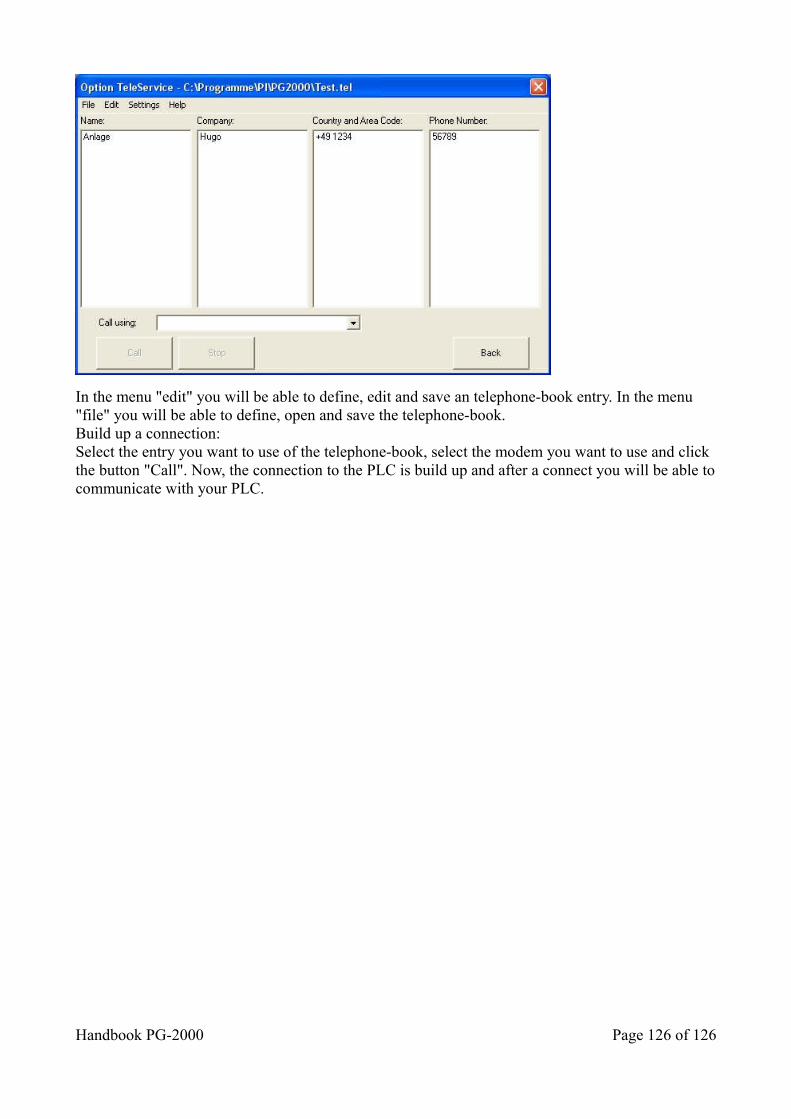
In the menu "edit" you will be able to define, edit and save an telephone-book entry. In the menu "file" you will be able to define, open and save the telephone-book.Build up a connection:Select the entry you want to use of the telephone-book, select the modem you want to use and click the button "Call". Now, the connection to the PLC is build up and after a connect you will be able tocommunicate with your PLC.
Handbook PG-2000 Page 126 of 126