Embed Size (px)
Citation preview
"Ho.darban.TCemen.Se.ninarH.OOi:m,ttW?IW
Engineering - Motor Control
Chapter 6
Motor Control
© Holderbank Management & Consulting, 2000 Page 179
"Holderbank" Cement Seminar 2000Engineering - Motor Control
Page 180 © Holderbank Management & Consulting, 2000
l!r.».»;l=7:iyTT^"Holderbank" Cement Seminar 2000
Engineering - Motor Control
Motor Control
Roland Luder
1 . INTRODUCTION 1 82
2. PROGRAMMABLE CONTROLLERS (PLC) 1 83
2.1 Introduction, History 183
2.2 Hardware of Programmable Controllers 184
2.3 Structure of a PLC • 186
2.4 Software of Programmable Controllers 187
2.5 Programming a PLC 188
2.6 Criteria governing the Choice of PLC 190
© Holderbank Management & Consulting, 2000 Page 1 81
"Holderbank" Cement Seminar 2000Engineering - Motor Control
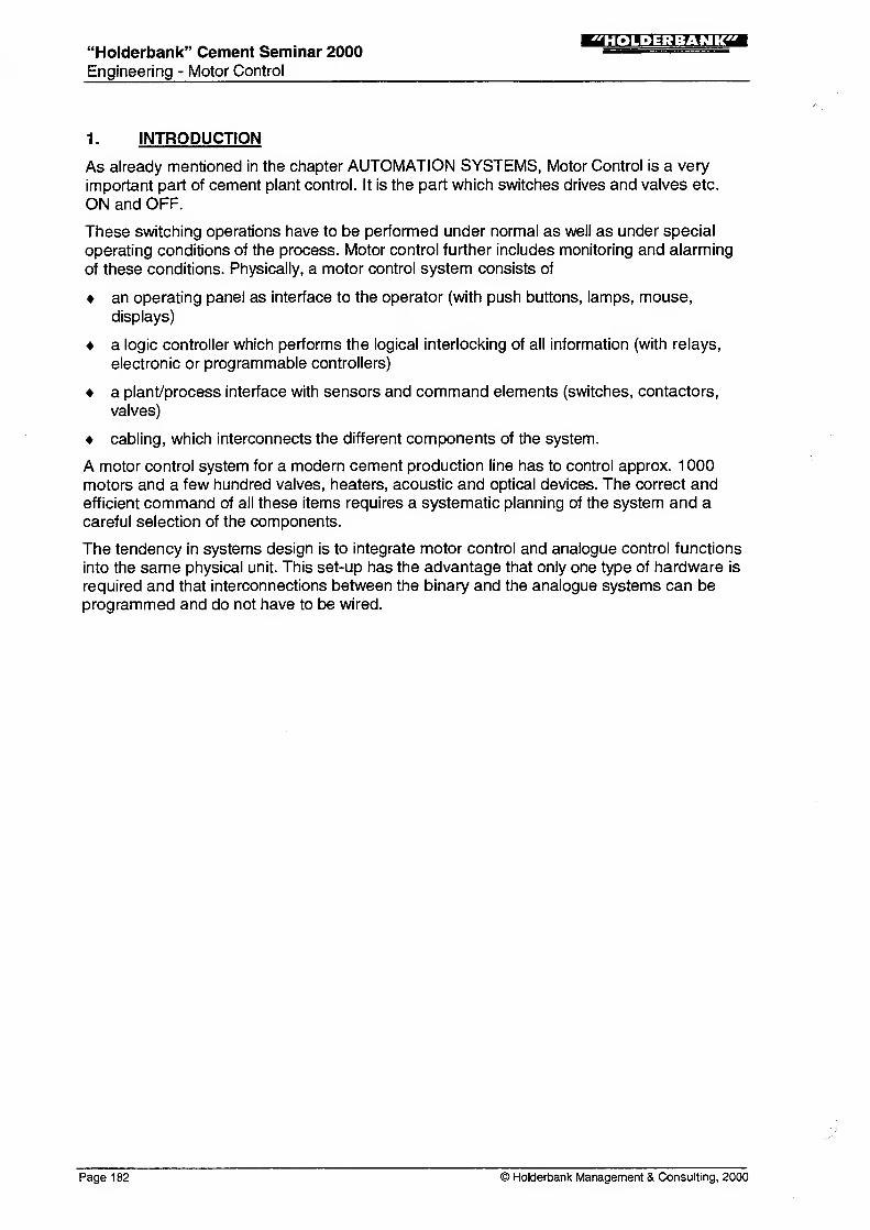
1. INTRODUCTION
As already mentioned in the chapter AUTOMATION SYSTEMS, Motor Control is a very
important part of cement plant control. It is the part which switches drives and valves etc.
ON and OFF.
These switching operations have to be performed under normal as well as under special
operating conditions of the process. Motor control further includes monitoring and alarming
of these conditions. Physically, a motor control system consists of
an operating panel as interface to the operator (with push buttons, lamps, mouse,
displays)
a logic controller which performs the logical interlocking of all information (with relays,
electronic or programmable controllers)
a plant/process interface with sensors and command elements (switches, contactors,
valves)
cabling, which interconnects the different components of the system.
A motor control system for a modern cement production line has to control approx. 1 000motors and a few hundred valves, heaters, acoustic and optical devices. The correct andefficient command of all these items requires a systematic planning of the system and acareful selection of the components.
The tendency in systems design is to integrate motor control and analogue control functions
into the same physical unit. This set-up has the advantage that only one type of hardware is
required and that interconnections between the binary and the analogue systems can beprogrammed and do not have to be wired.
Page 182 © Holderbank Management & Consulting, 2000
"Holderbank" Cement Seminar 2000
Engineering - Motor Control
2. PROGRAMMABLE CONTROLLERS (PLC)
2.1 Introduction, History
The logic controller is the brain of the motor control system, i.e. the decision-making part. It
takes care of the safe, convenient sequential starting, running and stopping of single motors
or of whole groups of machines.
There are basically three different techniques to build-up an electrical logic controller:
2.1.1 Relay Technology
A relay uses the electro-mechanical equipment which uses the electromagnetic force of an
electrical coil to open or close electrical contacts. The internal wiring of these coils and
contacts determines the specific function of the set-up.
Relays control has been the only technology until approx. 1 960.
Today relays are still used for interfacing (power amplifying) purposes and for very small
control systems.
2.1.2 Electronic Card System
This technology was developed in Europe and was applied approx. until 1 975. It consists of
electronic components, pre-assembled on printed circuit boards and performing specific
logic functions. The function of the total system is determined by the wiring between the
different logic cards.
Today these systems are hardly anymore installed.
2.1.3 Programmable Controllers
This technology was introduced in the market approx. 1 970, and is the today's dominating
technology. The tendency is to replace relays by programmable controllers even in very
small applications. The programmable controller uses basically the same idea as a
computer does: it uses a memory to store information and it uses this information to execute
step by step a procedure which is determined by this information (program; software).
The advantages of the programmable controllers as opposed to other technologies are:
No mechanical wear
no rewiring when modifications are required
easier planning (hardware / software can be planned in parallel)
higher level of automation is possible
integrated solutions with analogue control and data acquisition are possible.
© Holderbank Management & Consulting, 2000 Page 183
"Holderbank" Cement Seminar 2000Engineering - Motor Control
ii'm'Uii-.jurzza
2.2 Hardware of Programmable Controllers
A programmable controller is basically a 'BLACK BOX' with INPUTS and OUTPUTS and aconnection to a PROGRAMMING UNIT.
With the programming unit, the user determines how the different inputs and outputs mustbe logically correlated and sequenced to perform the desired control task. The programmingnowadays uses a PC to display, to enter or to modify the program as well as an additional
storage devices to safeguard it.
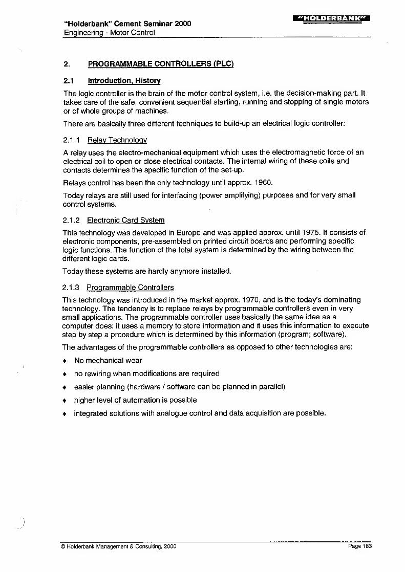
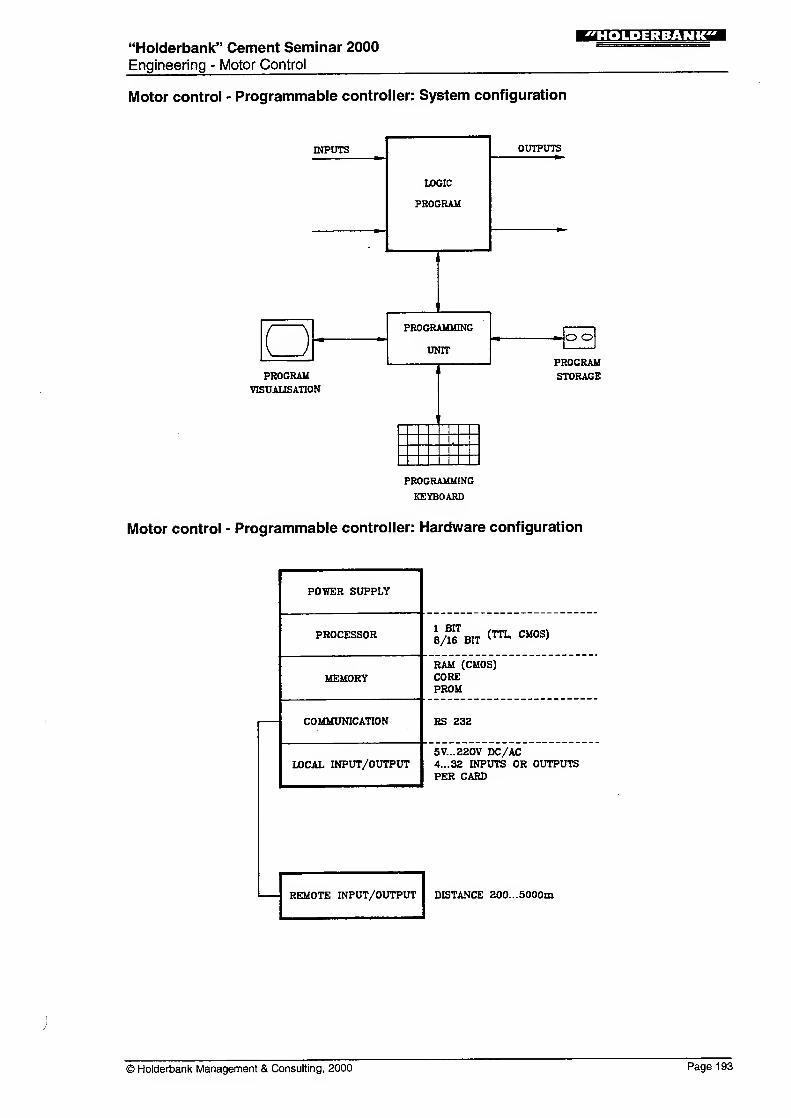
The 'BLACK BOX' is composed on one or several chassis or racks which basically contain
the following elements (see Fig. 2.2.1)
Figure 2.2.1 Programmable Controller
Hardware Configuration
1
)
Power supplyTo provide the internal stabilised control voltages of the programmable controller
2) ProcessorTo perform the actual logic / timing and internal control functions
3) MemoryTo store the program and data
4) Communication port
To communicate with external devices (as programming panel, computer, other
programmable controllers) or with remote input/output devices.
5) Input/Output (I/O) Devices
To transform the signal coming in (INPUT) from outside (e.g. from a level switch) or
going out (OUTPUT) to the outside (e.g. to lamps, to the MCC). Today mostprogrammable controllers handle as well analogue I/O signals.
Physically all these elements are generally grouped on one or several cards of the draw-out
type. The cards are internally interconnected via a system bus which performs a fast
exchange of the necessary information between the different cards.
This arrangement provides great flexibility in hardware planning: if additional memory spaceis required, for examples, it is generally sufficient to plug in an additional memory card. Thedraw-out technique, of course, also simplifies troubleshooting of the hardware (defective
card out - new card in - restart). It must be noted, however, that once a system is correctly
set-up, there are generally no more hardware failures.
Page 184 © Holderbank Management & Consulting, 2000
"Holderbank" Cement Seminar 2000
Engineering - Motor Control
:r*n.i=u^vrTsa
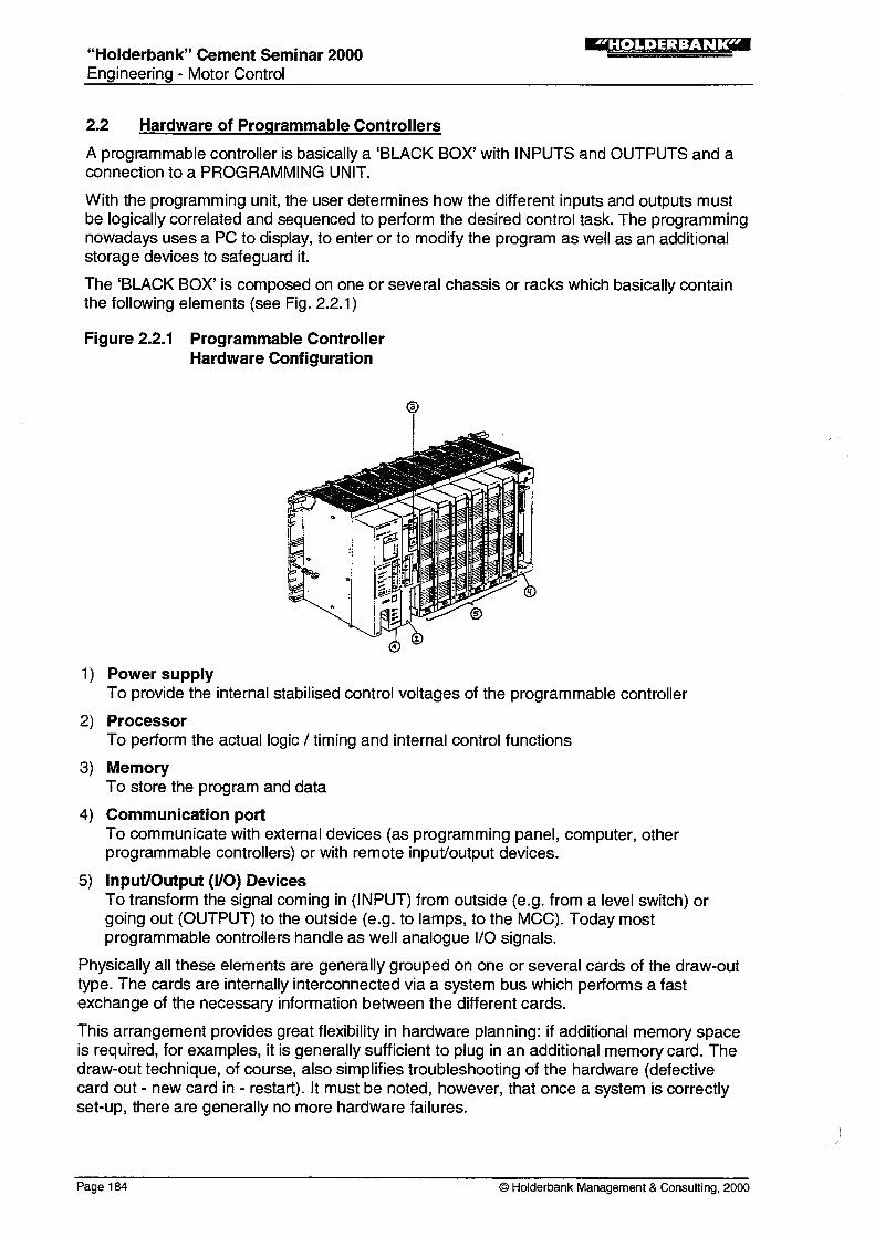
Figure 2.2.2 shows an example of an input card of the draw-out type which contains 16
inputs. Output cards may be arranged in a similar way.
Figure 2.2.2: INPUT (OUTPUT) Card of a Programmable Controller
Plug to the "bus" of the rack Plug to external wiring
(IN-/0UTPUTS)
/
///'ffii|
Address of the
IN-/0UTPUT
Status indication of
IN-/OUTPUTS
The size of a programmable controller can be expressed by different figures. The most
important figure is the number of I/O which a programmable controller can handle. The
smallest units start at approx. 1 5 I/O, the biggest go up to 8000 I/O.
The maximum memory size is another key figure which, however, generally goes in parallel
with the number of l/Os. Normal sizes range from approx. 0.5 K up to 1000 K (1 K = approx.
1000 program steps).
The cycle time (see 'software') generally goes in parallel with the size of the memory used
and is generally expressed in ms/1 K. It ranges from approx. 0.5 to 50 ms/1 K.
© Holderbank Management & Consulting, 2000 Page 185
"Holderbank" Cement Seminar 2000
Engineering - Motor Control
!M«.»;i:MJrCT
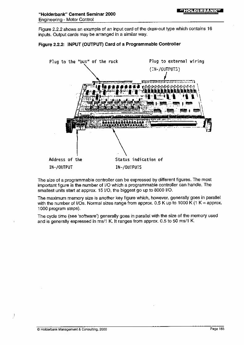
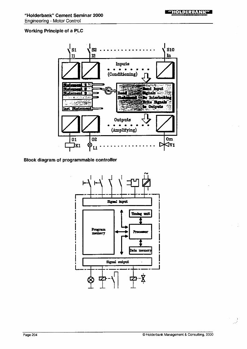
2.3 Structure of a PLC
The diagram below shows the structure of a PLC. The main functional elements of a
programmable logic controller are the control unit with one, or sometimes several micro-
processors and the corresponding memories for data (timers, counters, markers, etc.) and
programs (programmable memories).
Block diagram of programmable controller
The program memory, processor, counter, data memory and the input/output units are
interconnected. Here connection via bus has become standard practice. By means of this
bus the data are exchanged between data memory, processor and program memory.
2.3.1 Differences between PLC and a Computer
What are the main differences? In a PLC so-called bit processing is used. This is special
processing method which processes only one bit. In contrast, the computer always uses
word processors, i.e. single bits can only be addressed by programming.
A PLC functions in much the same way as a computer, but with the following main
differences.
User's programs are executed cyclically
A PLC needs a very simple operating system
The information is processed a bit at a time (facilities for word processing are available)
A PLC is a real-time system, i.e. the results of operations are obtained within a short,
clearly defined time
The set of command is especially intended for control requirements and is therefore
limited in its scope
Page 186 © Holderbank Management & Consulting, 2000
'Holderbank" Cement Seminar 2000
Engineering - Motor Control
The hardware is designed for rough industrial conditions (temperatures between -10 and
+60°C)
Programming is simple, can be understood by electricians and is easy to learn
Addressing of input and output cards is transparent
To program a PLC a special programming unit has to be connected to it.
2.4 Software of Programmable Controllers
In the chapter 'Hardware of Programmable Controllers' we have seen that a programmable
controller can be represented as a 'BLACK BOX' which contains inputs and outputs.
The different inputs and outputs have now to be logically and sequentially interconnected to
perform the desired control task. To represent this "logical and sequential interconnection",
special languages have been elaborated. Unfortunately, these languages or graphic
presentations are not standardised. Main differences can be found between European and
American presentations but even within one language, practically every suppliers uses his
own 'slang'.
For a long time there was a certain market tendency toward the ladder diagram, influenced
by the American market where generally only this language is used.
The ladder diagram is based on the representation which was used for relay systems. It can,
therefore, easily be learned by people who worked with those systems but it does not well
represent the new thinking in inputs/outputs.
Nowadays a standard is on the market named IEC1 131
.
Any logic can actually be represented with only 4 different instructions:
Logic AND, logic OR, logic NOT and TIME instruction. In order to make programming
easier, all programmable controllers use additional logic instructions which are composed of
specific often-used combinations of above four elements.
When a programmable controller is equipped to accept analogue inputs, additional
instructions for arithmetic operations and file handling are available.
For bigger applications (as e.g. in the cement industry) a structured programming making
use of 'macros' or subroutines should be applied. The same applies when analogue control
capabilities are included in the programmable controller.
The actual program is now composed of a series of program steps, every step uses a
combination of instructions or 'macros' to define how the different inputs have to be linked
with the outputs.
It is important to mention that the program is executed step by step. This means that one
instruction after the other is read, interpreted and executed.
At the end, the program automatically restarts at the beginning. The total time which a
program needs to come once from the beginning to the end is called the system cycle time.
This time is generally very short (approx. 1...300 ms). For an external observer of the
system it, therefore, behaves as if everything (all commands) would be immediately
executed - all at the same time. In reality, as explained, only one instruction is executed at
one time.
© Holderbank Management & Consulting, 2000 Page 187
"Holderbank" Cement Seminar 2000Engineering - Motor Control
'HOLDERBANK'
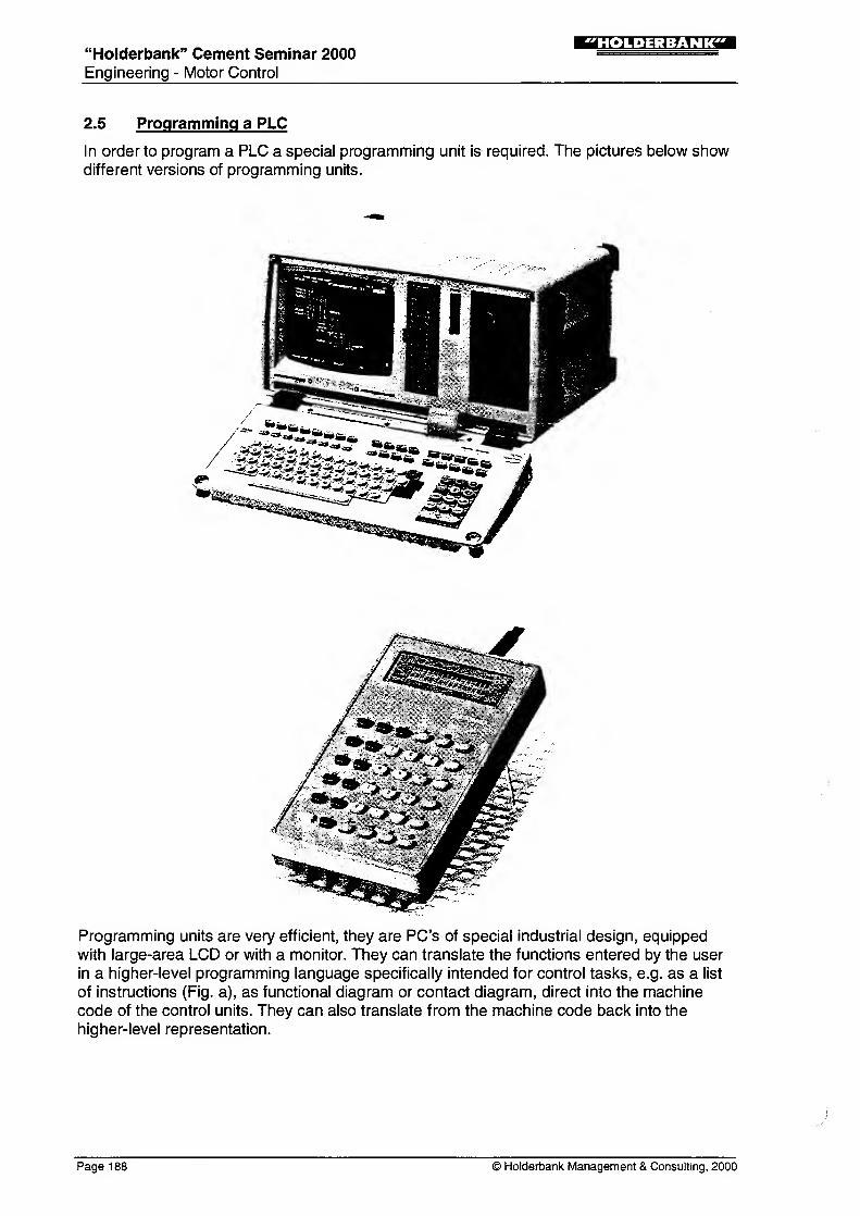
2.5 Programming a PLC
In order to program a PLC a special programming unit is required. The pictures below showdifferent versions of programming units.
Programming units are very efficient, they are PC's of special industrial design, equipped
with large-area LCD or with a monitor. They can translate the functions entered by the user
in a higher-level programming language specifically intended for control tasks, e.g. as a list
of instructions (Fig. a), as functional diagram or contact diagram, direct into the machine
code of the control units. They can also translate from the machine code back into the
higher-level representation.
Page 188 © Holderbank Management & Consulting, 2000
"Holderbank" Cement Seminar 2000
Engineering - Motor Control
!r*».»:J:M?TT
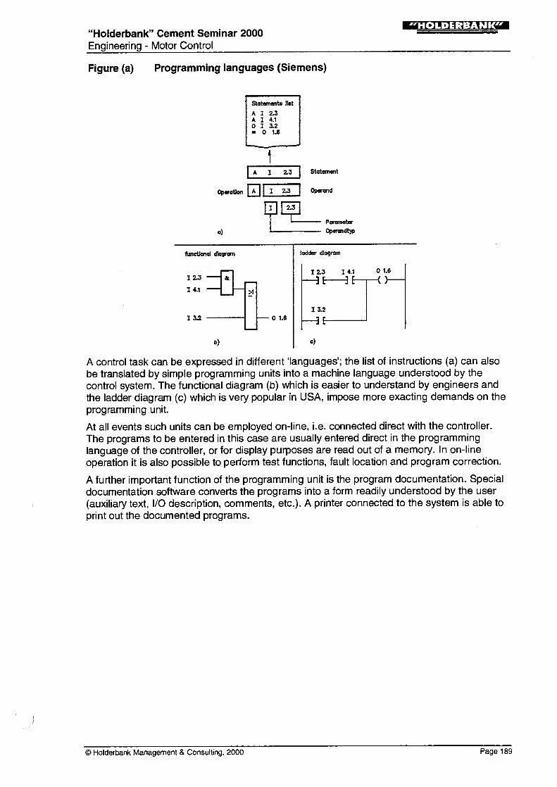
Figure (a) Programming languages (Siemens)
Statements list
AA
I
I
I
2.3
4.1
3.2
1.6
1
2.3 Statement
Operation | I 23 | Operand
HE^lParameter
Operandt)p
functional diagram
IZ3
14.1
13.2
>1
1.6
ladder diagram
b)
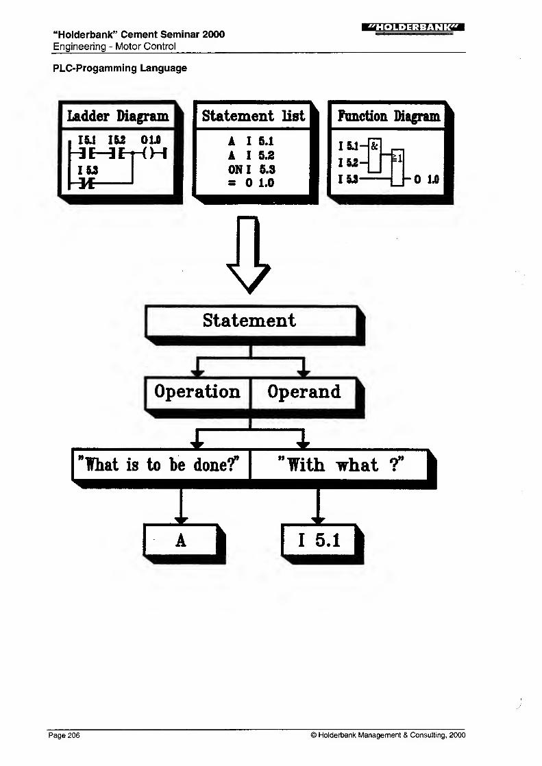
A control task can be expressed in different 'languages'; the list of instructions (a) can also
be translated by simple programming units into a machine language understood by the
control system. The functional diagram (b) which is easier to understand by engineers and
the ladder diagram (c) which is very popular in USA, impose more exacting demands on the
programming unit.
At all events such units can be employed on-line, i.e. connected direct with the controller.
The programs to be entered in this case are usually entered direct in the programming
language of the controller, or for display purposes are read out of a memory. In on-line
operation it is also possible to perform test functions, fault location and program correction.
A further important function of the programming unit is the program documentation. Special
documentation software converts the programs into a form readily understood by the user
(auxiliary text, I/O description, comments, etc.). A printer connected to the system is able to
print out the documented programs.
) Holderbank Management & Consulting, 2000 Page 189
rrr5n.»:i:Mjirq"Holderbank" Cement Seminar 2000
Engineering - Motor Control
2.6 Criteria governing the Choice of PLC
Basically, any PLC can be used for control tasks in the cement industry, provided it satisfies
to following requirements.
2.6.1 General
The system is well represented and generally known in the country
Spare parts are guaranteed obtainable at least for 10 years
The system must be capable for expansions in order to integrate future adaptations
The dimensions of equipment permit the replacement of existing facilities
2.6.2 Central Unit (CPU)
When the system is extended to full capacity, the cycle time should not exceed 1 50 ms
Adapted memory capacity, so that there is no shortage of storage capacity when the
system is fully expanded.
On-line programming of modifications while the process is in progress
Reasonable set of instructions containing the following:
arithmetic with variable decimal point, PID algorithms and functions specified by the
user, modules (e.g. motor module).
Floating point arithmetics
2.6.3 Communication
Between PLC's with bus
Standardised interface with simple protocol with a main-frame computer (e.g. RS 232,
RS 422, RS 485)
Standardised interface with subcontrol systems (field bus, profibus, RS 232)
2.6.4 Inputs/Outputs
Decentralised peripherals connected with the CPU by a serial line (possibly an optical
link)
24 V or 48 V DC single-ended inputs/outputs with common ground
4-20 mA analogue single-ended inputs/outputs with common ground
Capable of extension up to 2000 inputs and outputs
2.6.5 Programming and Documentation
Off-line programming and documentation with standard PC's
Remote line connection of programming units
Graphic representation, preferably by functional diagram
Symbolic programming of addresses with at least 1 5 freely chosen characters
Commands and operating instructions in the local language
Page 190 © Holderbank Management & Consulting, 2000
"Holderbank" Cement Seminar 2000Engineering - Motor Control
!r.».H;j:Mjr?aa
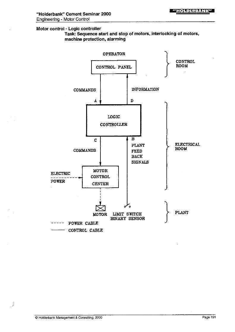
Motor control - Logic controller
Task: Sequence start and stop of motors, interlocking of motors,
machine protection, alarming
OPERATOR
CONTROL PANEL
COMMANDS
A i
v CONTROL* ROOM
INFORMATION
D
LOGIC
CONTROLLER
COMMANDS
ELECTRIC
POTTER
MOTORCONTROL
CENTER
IS)MOTOR
POWER CABLE
CONTROL CABLE
B
PLANT
FEEDBACKSIGNALS
>ELECTRICALROOM
So
LIMIT STOTCHBINARY SENSOR
PLANT
© Holderbank Management & Consulting, 2000 Page 191
"Holderbank" Cement Seminar 2000Engineering - Motor Control
!MMJ:iiM?ra
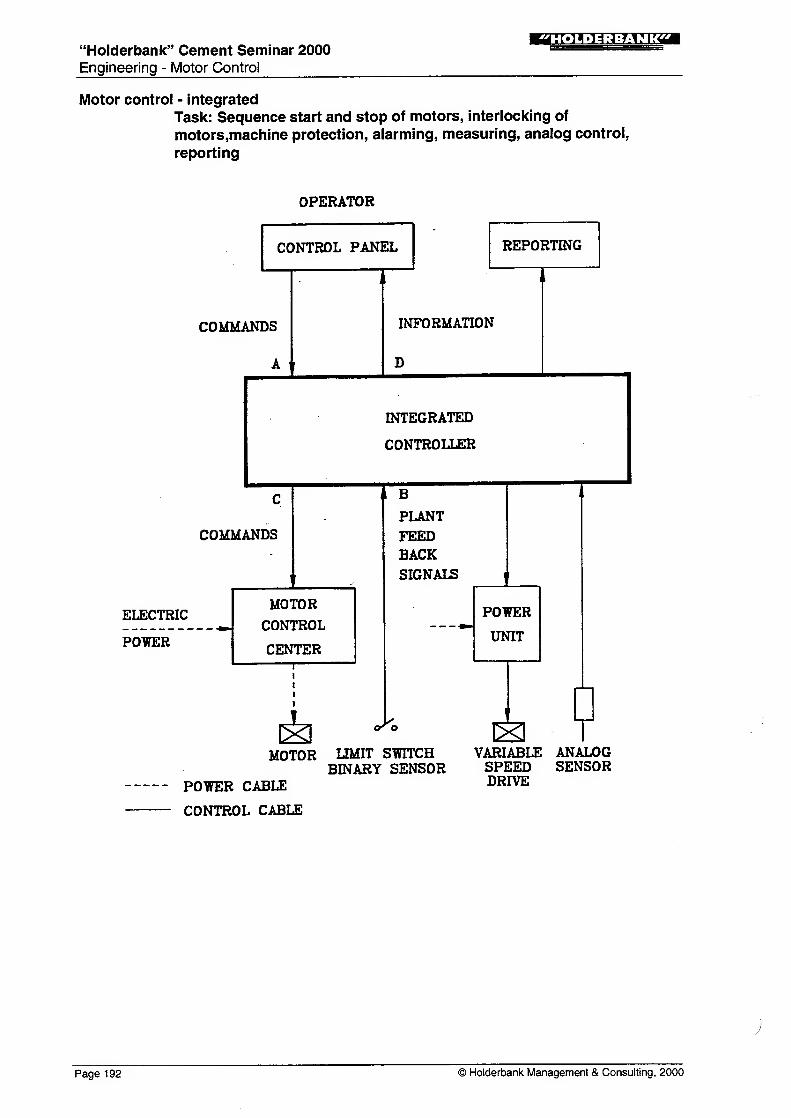
Motor control - integrated
Task: Sequence start and stop of motors, interlocking of
motors,machine protection, alarming, measuring, analog control,
reporting
OPERATOR
CONTROL PANEL
COMMANDS
A t
COMMANDS
ELECTRIC
POWER
MOTOR
CONTROL
CENTER
REPORTING
INFORMATION
D
INTEGRATED
CONTROLLER
I B
PLANT
FEEDBACKSIGNALS
o^o
MOTOR LIMIT SWITCHBINARY SENSOR
POWER CABLE
CONTROL CABLE
VARIABLE ANALOGSPEED SENSORDRIVE
Page 192 © Holderbank Management & Consulting, 2000
"Holderbank" Cement Seminar 2000
Engineering - Motor Control
;r»n.H:j=M^rrga
Motor control - Programmable controller: System configuration
INPUTS
oPROGRAM
VISUALISATION
LOGIC
PROGRAM
PROGRAMMING
UNIT
PROGRAMMING
KEYBOARD
OUTPUTS
O OPROGRAMSTORAGE
Motor control - Programmable controller: Hardware configuration
POTOR SUPPLY
PROCESSOR
MEMORY
COMMUNICATION
LOCAL INPUT/OUTPUT
REMOTE INPUT/OUTPUT
B/^BIT <™* CU0S>
RAM (CMOS)COREPROM
RS 232
5V...220V DC/AC4...32 INPUTS OR OUTPUTSPER CARD
DISTANCE 200...5000m
© Holderbank Management & Consulting, 2000 Page 193
"Holderbank" Cement Seminar 2000
Engineering - Motor Control
!r»».»;i=M?l?gl
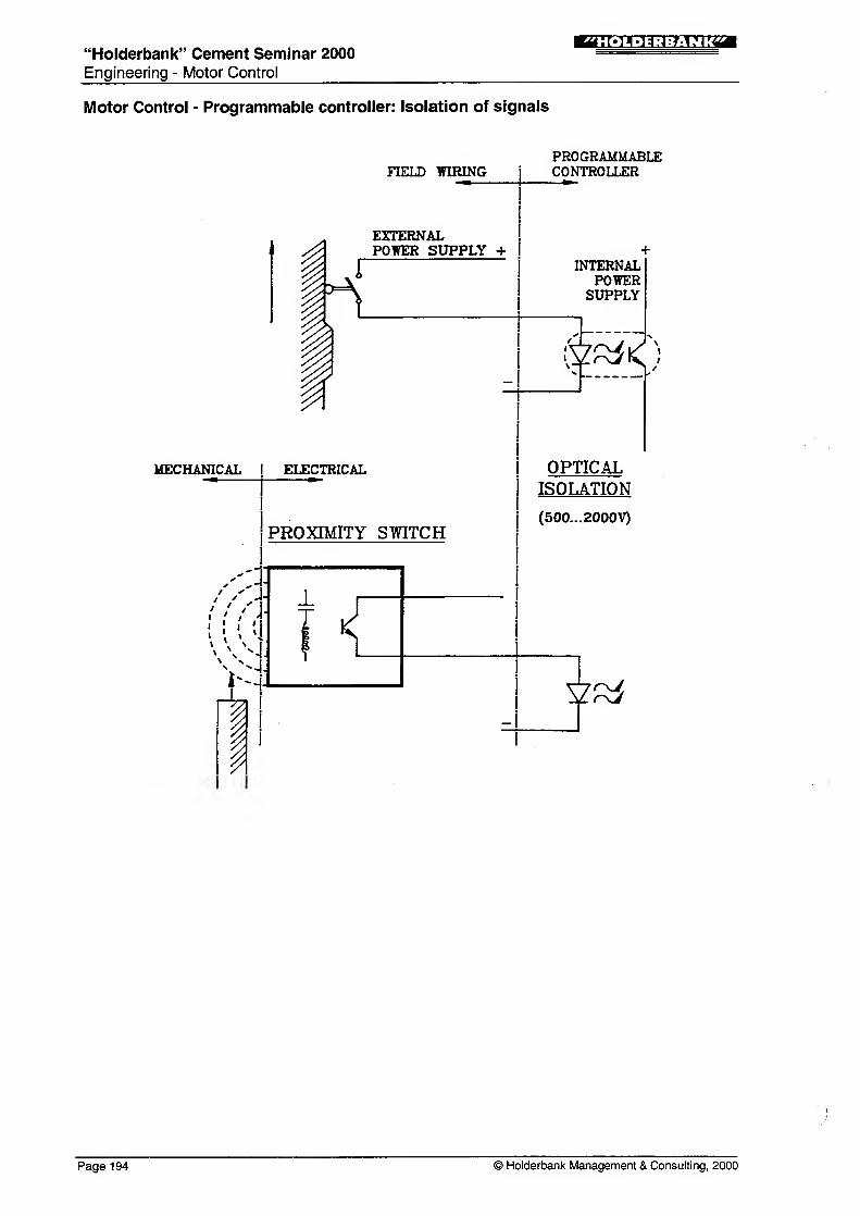
Motor Control - Programmable controller: Isolation of signals
MECHANICAL
HELD WIRING
. EXTERNALst, POWER SUPPLY -f
IP
iELECTRICAL
PROXIMITY SWITCH
PROGRAMMABLECONTROLLER
INTERNALPOWERSUPPLY
:«*<)
OPTICALISOLATION
(500...2000V)
Page 194 © Holderbank Management & Consulting, 2000
"Holderbank" Cement Seminar 2000Engineering - Motor Control
:Mi.H:j:M?rTzai
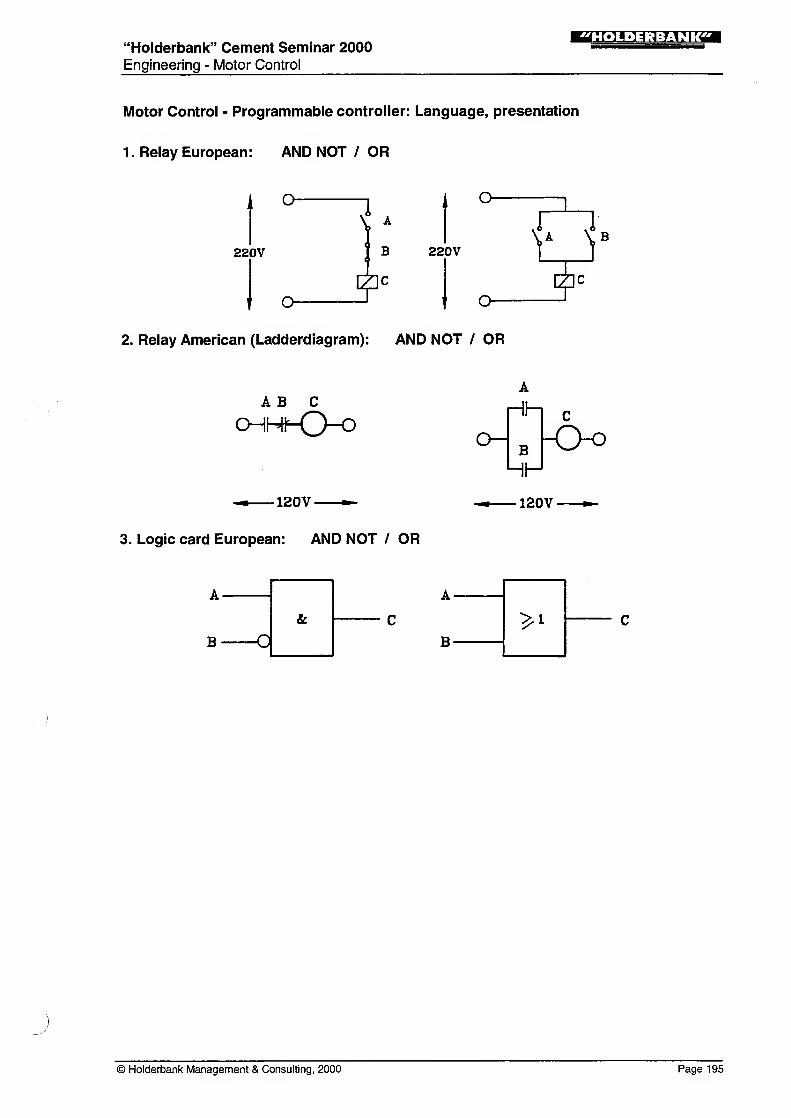
Motor Control - Programmable controller: Language, presentation
1. Relay European: AND NOT / OR
O O-
220V B 220V
IC
f o- t olie
2. Relay American (Ladderdiagram): AND NOT / OR
A B C
CHHhQ-O
•120V-
3. Logic card European: AND NOT / OR
A
Hh c
°~B -O-O
•120V
B O
© Holderbank Management & Consulting, 2000 Page 195
"Holderbank" Cement Seminar 2000Engineering - Motor Control
iMMJ:J:MJP:
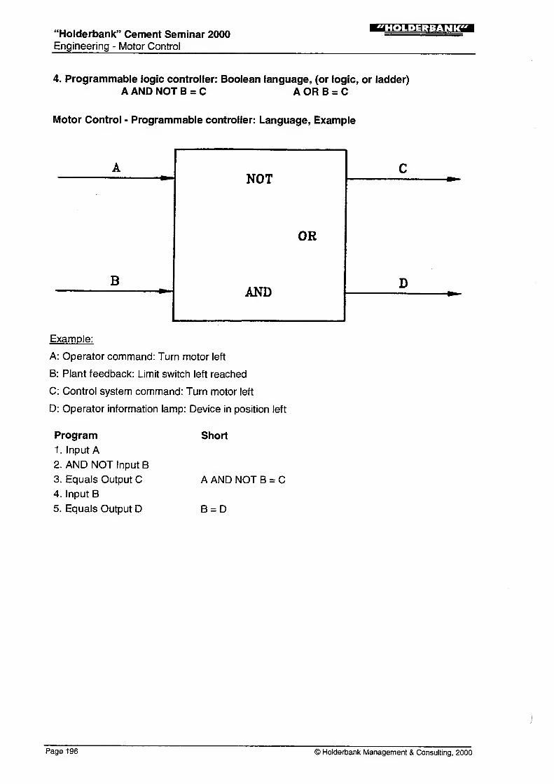
4. Programmable logic controller: Boolean language, (or logic, or ladder)
A AND NOT B = C A OR B = C
Motor Control - Programmable controller: Language, Example
ANOT
C
OR
BAND
D
Example:
A: Operator command: Turn motor left
B: Plant feedback: Limit switch left reached
C: Control system command: Turn motor left
D: Operator information lamp: Device in position left
Program
1. Input A2. AND NOT Input B
3. Equals Output C4. Input B
5. Equals Output D
Short
A AND NOT B = C
B = D
Page 196 © Holderbank Management & Consulting, 2000
"Holderbank" Cement Seminar 2000
Engineering - Motor Control
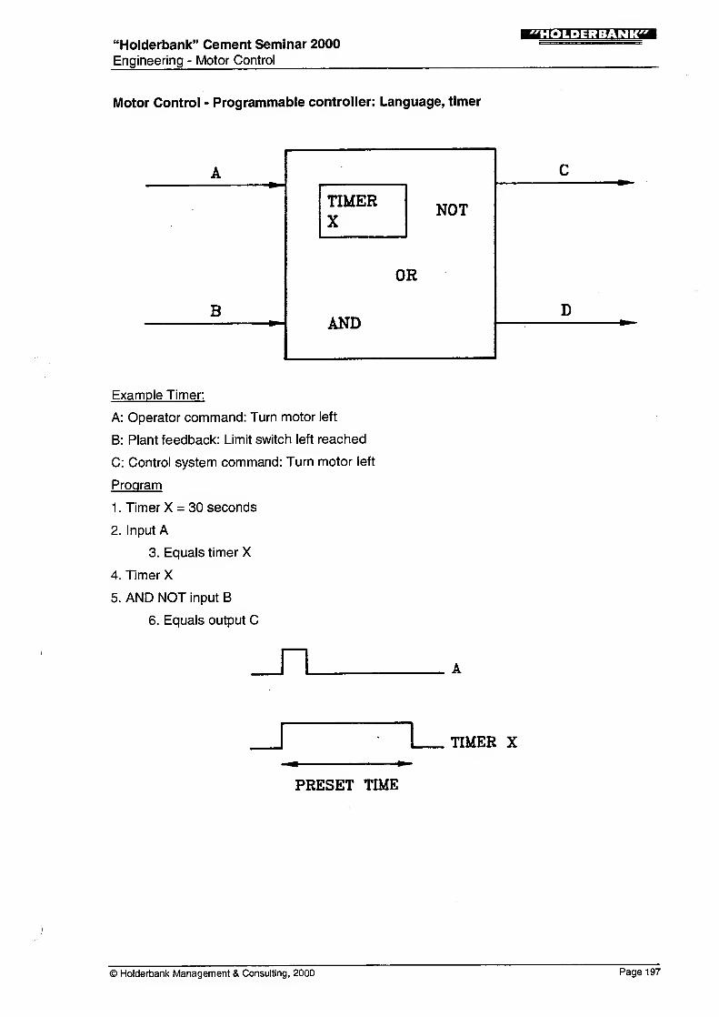
Motor Control - Programmable controller: Language, timer
A
NOT
C
TIMERX
DBAND
OR
Example Timer:
A: Operator command: Turn motor left
B: Plant feedback: Limit switch left reached
C: Control system command: Turn motor left
Program
1
.
Timer X = 30 seconds
2. Input A
3. Equals timer X
4. Timer X
5. AND NOT input B
6. Equals output C
_n
_r L_ TIMER X
PRESET TIME
© Holderbank Management & Consulting, 2000 Page 197
"Holderbank" Cement Seminar 2000
Engineering - Motor Control
!MI.»;J=M?rCT
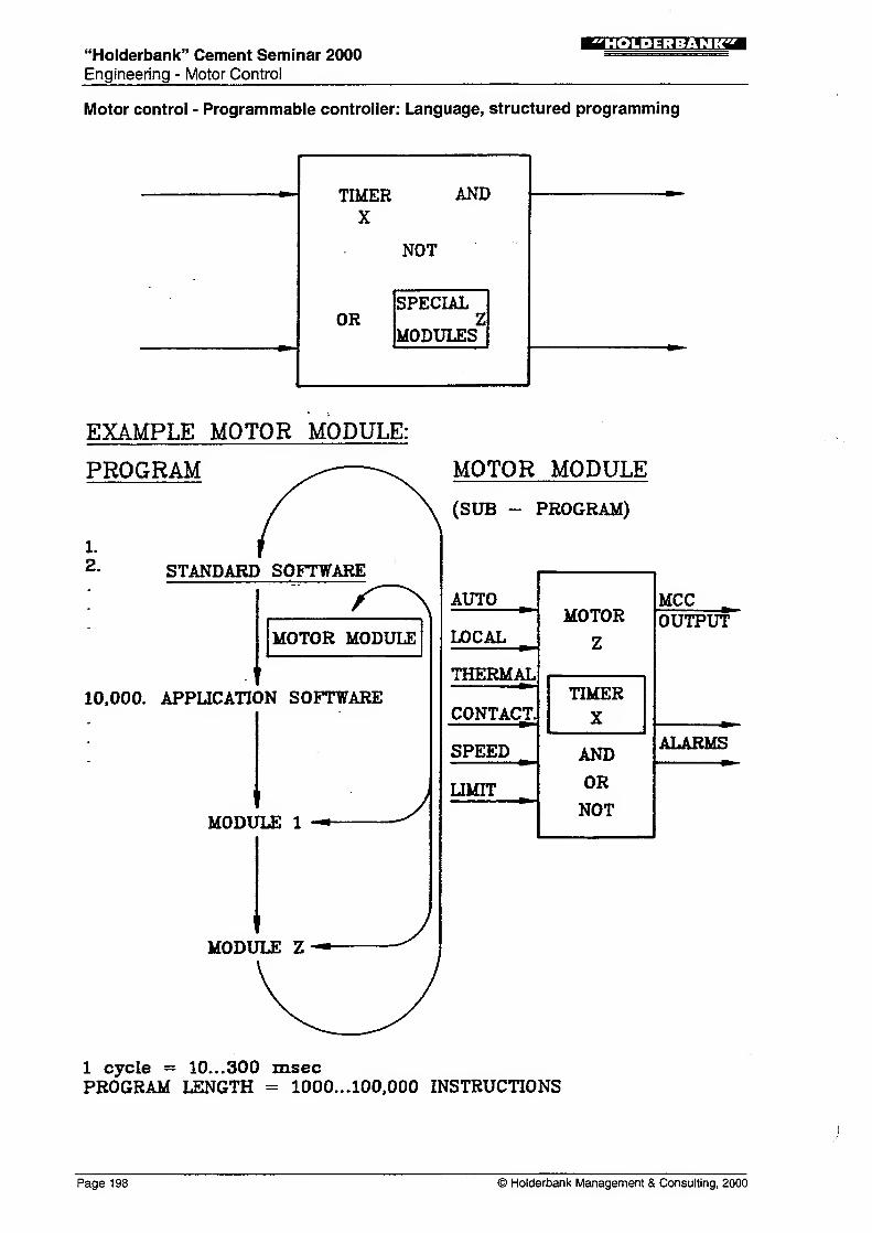
Motor control - Programmable controller: Language, structured programming
TIMERX
ANE
NOT
1
ORSPECIAL
ZMODULES
EXAMPLE MOTOR MODULE:
PROGRAM MOTOR MODULE
l.
2. STANDARD SOFTWARE
MOTOR MODULE
10.000. APPLICATION SOFTWARE
MODULE 1
MODULE Z
J
(SUB - PROGRAM)
AUTOMOTOR
Z
MCC
LOCALOUTPUT
THERMALTIMER
XCONTACT.^^
SPEED AND
OR
NOT
ALARMS
LIMIT
1 cycle = 10.. .300 msecPROGRAM LENGTH = 1000...100,000 INSTRUCTIONS
Page 198 © Holderbank Management & Consulting, 2000
"Holderbank" Cement Seminar 2000
Engineering - Motor Control
SMLHrJ^VrT
Understanding Computer Technology
Understanding Computer Technology
aoppy DISK,
MAIN
STORAGE
NORMAL FLOWOF OPERATION
SURGE CONTROL
DEVICE
PERIPHERALS
(HARDWARE)
DE-BUGGING
TOOL
MOUSE
FUNCTION
KEY
•APPLICATION
SOFTWARE
~fc2 BACKUPSYSTEM
USER INTERFACE
CENTRAL
PROCESSING
UNIT
OUTPUT
OVERFLOW(INPUT/OUTPUT
ERROR)
SUPPLEMENTARYDATA
© Holderbank Management & Consulting, 2000 Page 1 99
"Holderbank" Cement Seminar 2000Engineering - Motor Control
:i'm-U;iXMixm
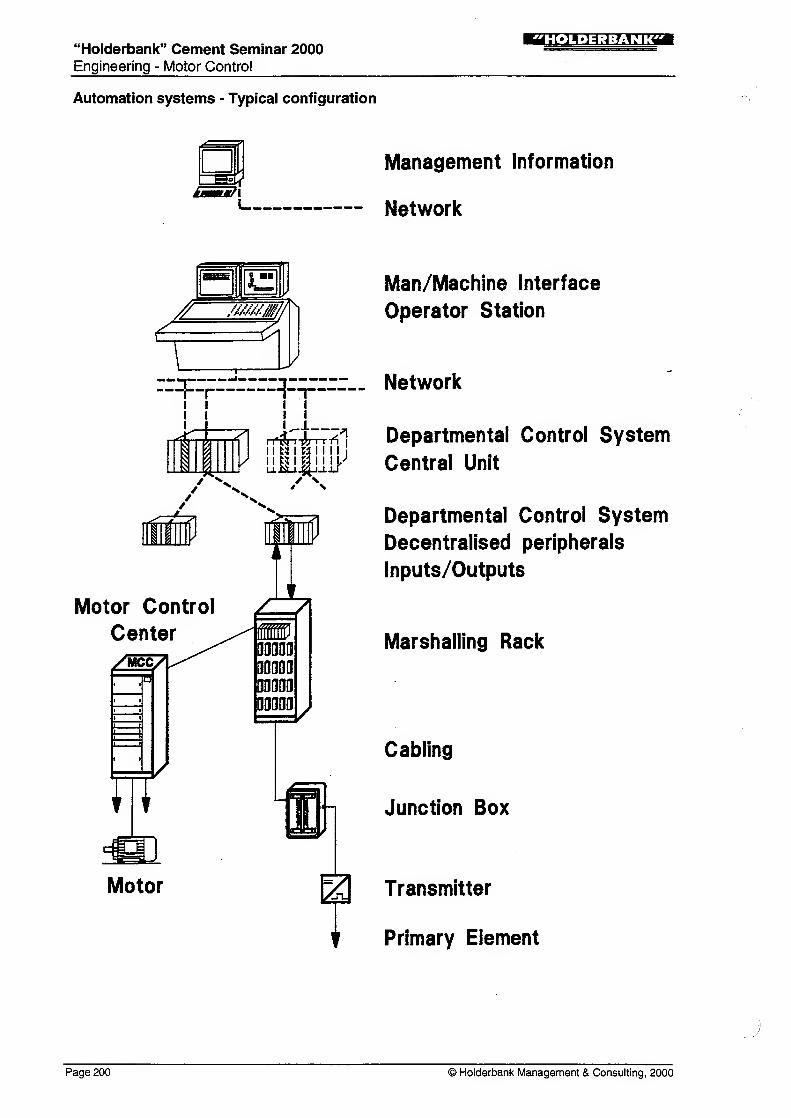
Automation systems - Typical configuration
:s»immm/X
Management Information
Network
-^FF^^FF-
/
/ n
m
Motor Control
Center
XMCC/.p
wMotor
i i
i i
ui A1 1 M I M I I 1
1
>siD
zii90011(1
00000
00000
00000
Man/Machine Interface
Operator Station
__ Network
Departmental Control System
Central Unit
Departmental Control System
Decentralised peripherals
Inputs/Outputs
Marshalling Rack
Cabling
Junction Box
2^ Transmitter
Primary Element
Page 200 © Holderbank Management & Consulting, 2000
"Holderbank" Cement Seminar 2000
Engineering - Motor Control
"HOLDERBANK"
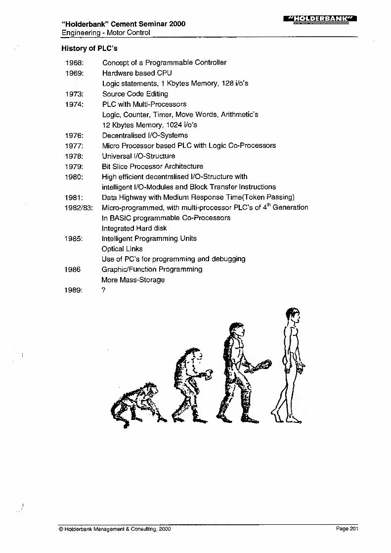
History of PLC's
1 968: Concept of a Programmable Controller
1969: Hardware based CPU
Logic statements, 1 Kbytes Memory, 128 i/o's
1 973: Source Code Editing
1 974: PLC with Multi-Processors
Logic, Counter, Timer, Move Words, Arithmetic's
12 Kbytes Memory, 1024 i/o's
1 976: Decentralised l/O-Systems
1 977: Micro Processor based PLC with Logic Co-Processors
1 978: Universal l/O-Structure
1 979: Bit Slice Processor Architecture
1 980: High efficient decentralised l/O-Structure with
intelligent l/O-Modules and Block Transfer Instructions
1 981
:
Data Highway with Medium Response Time(Token Passing)
1 982/83: Micro-programmed, with multi-processor PLC's of 4thGeneration
In BASIC programmable Co-Processors
Integrated Hard disk
1985: Intelligent Programming Units
Optical Links
Use of PC's for programming and debugging
1986 Graphic/Function Programming
More Mass-Storage
1989: ?
© Holderbank Management & Consulting, 2000 Page 201
"Holderbank" Cement Seminar 2000
Engineering - Motor Control
!N».»;i=M?rrai
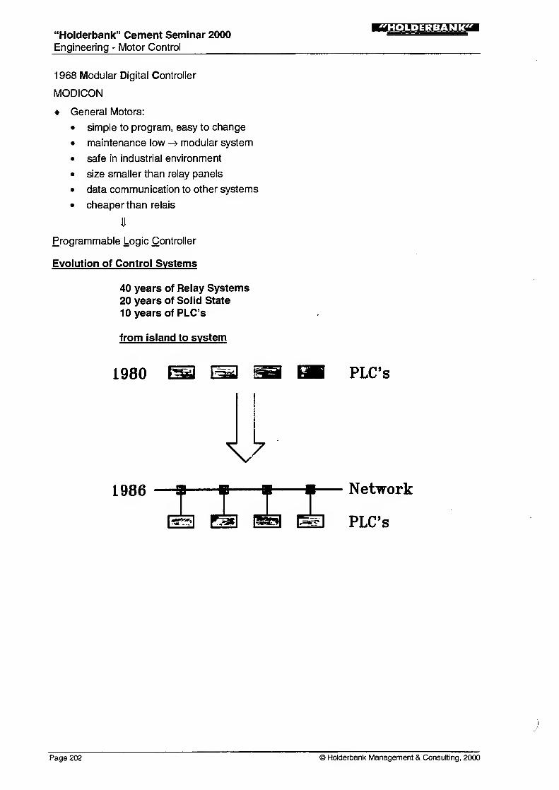
1 968 Modular Digital Controller
MODICON
General Motors:
• simple to program, easy to change
• maintenance low -> modular system
• safe in industrial environment
• size smaller than relay panels
• data communication to other systems
• cheaper than relais
Programmable Logic Controller
Evolution of Control Systems
40 years of Relay Systems20 years of Solid State
10 years of PLC's
from island to system
1980 PLC's
V7
1986
Page 202 © Holderbank Management & Consulting, 2000
"Holderbank" Cement Seminar 2000Engineering - Motor Control
"HOLDERBANK"
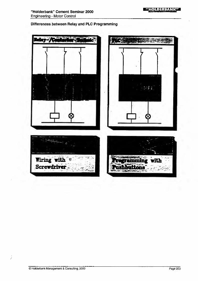
Differences between Relay and PLC Programming
© Holderbank Management & Consulting, 2000 Page 203
"Holderbank" Cement Seminar 2000Engineering - Motor Control
!MI.»;1=M?P
Working Principle of a PLC
Block diagram of programmable controller
Page 204 © Holderbank Management & Consulting, 2000
"Holderbank" Cement Seminar 2000
Engineering - Motor Control
IMn.U-A-.hMTTSM
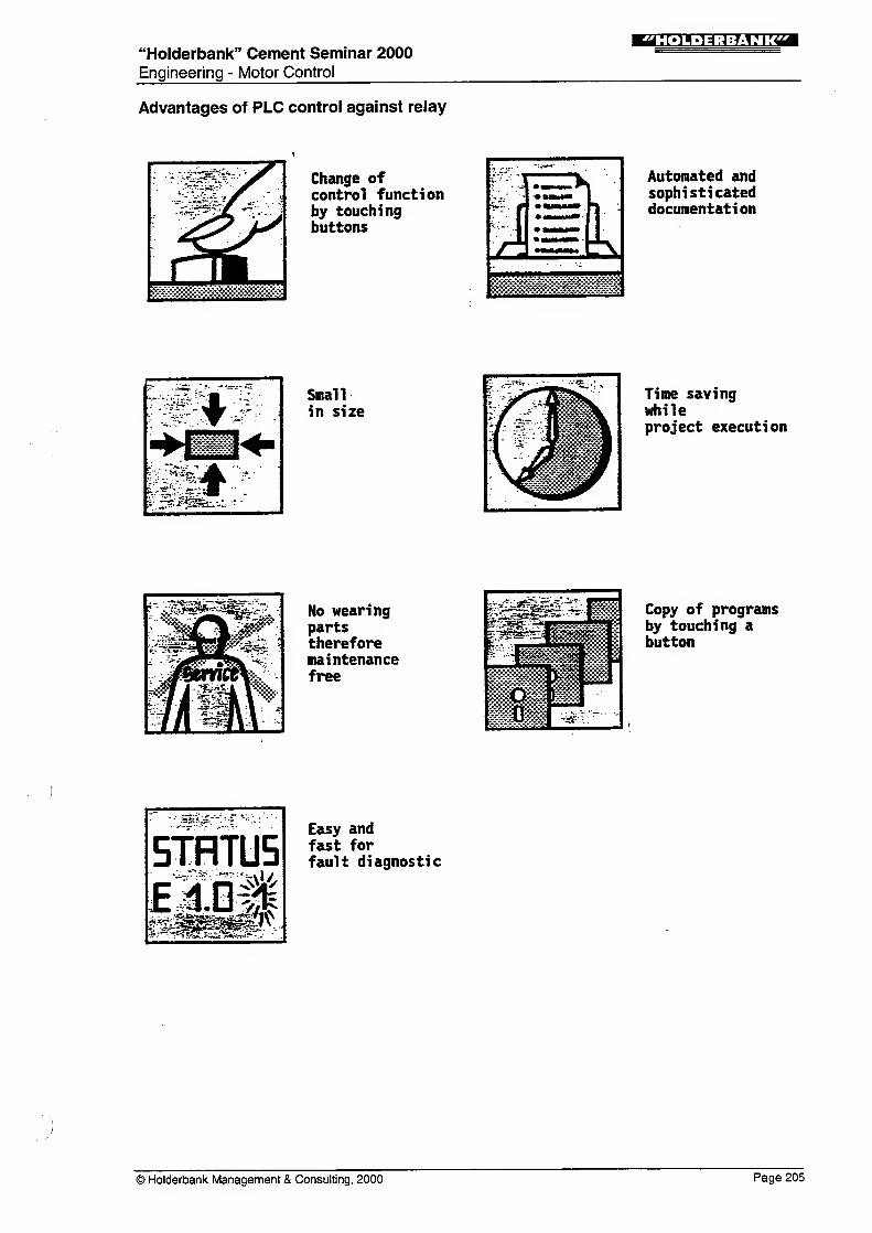
Advantages of PLC control against relay
Change ofcontrol functionby touchingbuttons
•;v .v'T
mmmn
Automated andsophisticateddocumentation
Small
in size
Time savingwhileproject execution
No wearingpartsthereforemaintenancefree
'^rSsfc- i iniArttf- -*^V"-* JAv.w.vvv.;.;.; .\
*H
Copy of programsby touching abutton
Easy andfast forfault diagnostic
© Holderbank Management & Consulting, 2000 Page 205
"Holderbank" Cement Seminar 2000Engineering - Motor Control
;r.».»:j:M?r?^a
PLC-Progamming Language
Ladder Diagram
15.1 152 oto
h^E-1 Er-(H
Statement
Function Diagram
I5.1-&
I52-_i«
—
I
Operation OperandI
Page 206 © Holderbank Management & Consulting, 2000