Embed Size (px)
Citation preview

1
PG&E 500 kV Series-Compensated Transmission Line Relay Replacement: Design Requirements and RTDS
Testing
PG&E
Davis ErwinRafael PinedaMonica Anderson
SEL, Inc.
Demetrios A.TziouvarasRick Turner

2
• Existing solid-state relay systems reached
the end of their useful life
• Systems placed out-of-service because of
• Misoperations and
• Lack of replacement parts
• Risk of forcing 500kV lines out of service
• NERC could impose substantial monetary
fines
Present Reliability of 500kV Protection

3
• Six lines required immediate relay system
replacement to:
• Improve reliability
• Maintain maximum availability
• Used existing protection design philosophy
on 5 of the 6 lines
• The 6th line required special considerations
not covered by this paper
Mitigation Plan

4
Project Flow
Define
Project Scope
Targeted relay
replacement,
maintain
existing
scheme
philosophy
Engineering Design
Develop Settings
Based on steady-
state fault studies
Develop
RTDS Model
Gather detailed
system data;
determine
boundaries
RTDS Testing
Prove and
adjust settings
Field Work
Obtain
clearances;
install and
commission
test devices

5
Relay Replacement Project
Permissive Overreaching Transfer Trip (POTT)
Set A- Dedicated Microwave
Set B or C- Switchable Carrier
Project Replacement
No high speed communication
Set D- Time Delayed Back-Up
Set A552-2
552-1
Set D
Set B
Set C

6
• Improve system transient stability
• Maintain 500kV system availability
• Reduce damage to insulators and
conductors
• Permit high-speed reclosing
• Reduced Zone 1 reach in SC lines
• One level of high-speed pilot protection is
required at all times for coordination
Justification for High-Speed Protection

7
Series-Compensated Line Protection ChallengesVoltage Inversion

8
Series-Compensated Line Protection ChallengesCurrent Inversion

9
Series-Compensated Line Protection ChallengesSubharmonic Oscillations
Zone 1 distance element overreach
0 2
X (
Oh
ms)
1-1-2
4
3
2
1
0
R (Ohms)
10
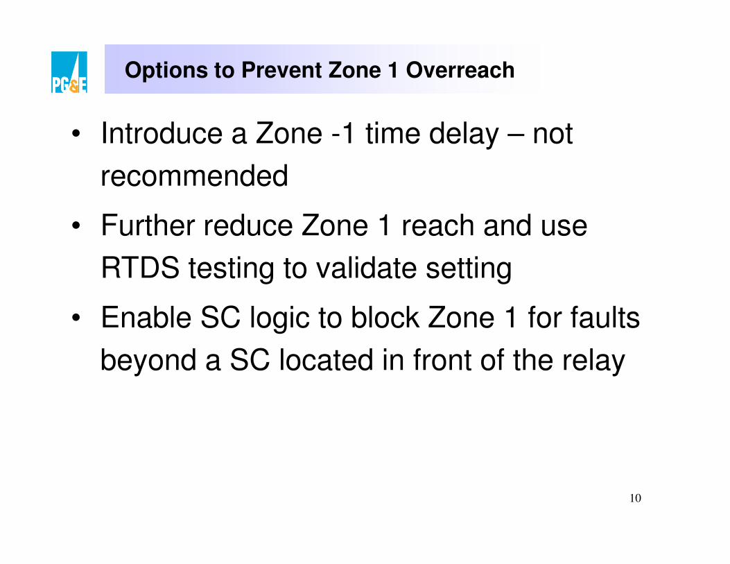
• Introduce a Zone -1 time delay – not
recommended
• Further reduce Zone 1 reach and use
RTDS testing to validate setting
• Enable SC logic to block Zone 1 for faults
beyond a SC located in front of the relay
Options to Prevent Zone 1 Overreach

11
• Used steady-state short circuit fault data
to develop initial relay settings
• Steady-state short circuit program cannot
model series compensation transients
• Relay settings for SC lines should be
verified using RTDS transient testing
Relay Setting Considerations and Criteria

12
West-Generator Station Line Under Study
Line under study
13
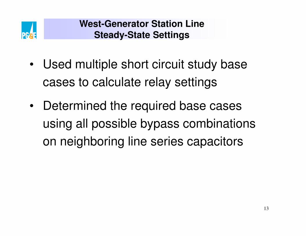
West-Generator Station LineSteady-State Settings
• Used multiple short circuit study base
cases to calculate relay settings
• Determined the required base cases
using all possible bypass combinations
on neighboring line series capacitors

14
Bypassed Capacitors

15
Steady-State Settings for West-Generator Station Line
• Determined minimum and maximum fault
currents and apparent impedances for
the line under study
• Considered additional cases because a
generator or transformer can be off-line
for extended periods
• Used an Excel macro to tabulate all of
the single outage contingencies

16
Cases Created for West-Generator Station Line
Fault Data
Case South PathNorth –South
North –West
West –South
1
2 BP
3 BP
4 BP BP
5 BP
6 BP BP
7 BP BP
8 BP BP BP
9 BP
10 BP BP
11 BP BP
12 BP BP BP
13 BP BP
14 BP BP BP
15 BP BP BP
16 BP BP BP BP

17
External Faults Past Capacitors

18
Series Compensation LogicGenerator Station
• Observed lower apparent impedances at
the GS for faults beyond the SCs on the
• North-West and
• South-West lines
• Used the series compensation logic to
block Zone 1 for a fault beyond a capacitor
• Applied a capacitor setting equal to the
highest XC value at the West bus

19
Series Compensation LogicWest Station
• Enabled series compensation logic
• Set XC to “OFF”
• Allows setting the Zone 1 element to
• Desired sensitivity
• Be secure during voltage inversions for
faults on neighboring SC lines

20
Custom Secure Echo Back POTT Logic

21
Custom Secure Echo Back POTT Logic
• Supervised logic by all poles being open
• Prohibits echo keying for subsequent out-
of-section faults that occur during single-
pole open conditions
• Feedback loop ensures that a 4-cycle
echo only occurs once per 10-cycle
period
22
RTDS Modeling
• Accurately modeled network around the
line under test
• Created reduced network model
• Matched load flow and short circuit currents
• Modeled SC MOV and TPSC protection
• SC bypass breakers and their controls
• High-MOV energy and current bypass
• SC reinsertion controls

23
RTDS Modeling
• Simulated single- and three-pole reclosing
controls for line under test
• Simulated relay operation and reclosing
controls for adjacent lines
• Modeled CCVT transient response
• Modeled frequency dependence of lines

24
RTDS Testing
25
• Continuous real time with a 50 – 70 µsec
time step
• Simulator is connected directly to relays
• COMTRADE files
• Analog voltages and currents
• Monitored pertinent digital elements to
capture as discrete points in time
RTDS Testing

26
RTDS Testing Order
• Compare RTDS fault currents with short circuit steady-state base case
• Verify proper connections to the relays and RTDS
• Perform manual tests for extreme conditions
• Perform scripted tests for
• External faults
• Internal faults

27
RTDS Manual Testing
• Verify relay operation for
• Switch on to fault
• Loss of potential and
• Faults during a single-pole trip open interval
• Apply ground faults with varying fault resistance
• At the zero-sequence center of the line
• Determine relay sensitivity for High-R faults

28
• Tests relays with different level of dc transients
• Generates different levels of subharmonic
frequency transients
RTDS TestingVariation of Fault Inception Angle
VA
0º 90º
45º

29
Automatic RTDS Scripting
• Automates fault simulation and data collection
• Generates thousands of test cases in a relatively short period of time
• Software analysis tools simplify the analysis of the large amount of data

30
Faults for One RTDS Script Test
Power Flow Cases &
Contingencies
4
Fault Locations 10
Fault Types 10
Fault Inception Angles 3
Total (4 • 10 • 10 • 3) = 1,200
31
RTDS ASCII File Discrete Points
– Reclose block and initiate
– Zone 1 pickup (phase or ground)
– Zone 2 pickup (phase or ground)
– POTT forward ground overcurrent pickup
– POTT key permissive
– POTT receive permissive
– POTT reverse element pickup
– Series compensation block Zone 1
– Out-of-step blocking (if utilizing this element)

32
RTDS Data Capture
• Captured the operating time of the monitored points in a text file
• Created a file for each fault location within each tested scenario

33
• Created an Excel workbook to assist in the data analysis
• The workbook utilizes a VB macro
• Analyzed internal and external fault simulation data
• Graphs illustrate important data results
RTDS Data Manipulation

34
• Formatted cells indicate relay tripping action (green) and nonaction (red)
RTDS Internal Fault Data Manipulation

35
RTDS Internal Fault Data Manipulation
Relay Operating Time – Left Terminal
Fault Location 5 (30 faults per case, 10% from generator bus)
Left Generator Terminal Zone 1 Statistics
Case1I_G 2U_A 2U_C 2U_E
30
25
20
15
10
5
0
0.049
0.042
0.033
0.025
0.017
0.008
Seconds
30
25
20
15
10
5
0
Number of Zone 1
Operations

36
• Formulas calculate the results of the Zone 1 elements for each line terminal as a percentage of all faults simulated at each location
• The histogram displays the effect of the right terminal adjacent line series capacitors on the Zone 1 reach of the left terminal
RTDS Internal Fault Data Manipulation

37
RTDS Internal Fault Data Manipulation

38
RTDS External Fault Data Manipulation

39
RTDS External Fault Data Manipulation
• The summary worksheet has two tables
• One table displays the results of the relays
for faults behind the left terminal
• The other presents the results for faults
behind the right terminal
• For each fault location, a column is
created with four rows of data

40
RTDS External Fault Data Manipulation

41
Conclusions
• RTDS transient testing is the best method
to verify relay settings and custom logic
• Increases familiarity with applied relays
and 500kV SC system transients
• Helps to identify and improve relay designs
• Provides updated 500kV transient model
for future project work
• Ready pool of COMTRADE files for
accurate field End-to-End testing