Embed Size (px)
Citation preview

Service ManualPGP020™
Effective: July 1, 2006Supersedes: All Others
Service Manual HY09-SM020/US
PGP020 Series

Parker Hannifin CorporationGear Pump DivisionYoungstown, Ohio USA
2
FAILURE OR IMPROPER SELECTION OR IMPROPER USE OF THE PRODUCTS AND/OR SYSTEMS DESCRIBED HEREIN OR RELATED ITEMS CAN CAUSE DEATH, PERSONALINJURY AND PROPERTY DAMAGE.
This document and other information from Parker Hannifin Corporation, its subsidiaries and authorized distributors provide product and/or system options for further investigation by usershaving technical expertise. It is important that you analyze all aspects of your application and review the information concerning the product or system in the current product catalog. Dueto the variety of operating conditions and applications for these products or systems, the user, through its own analysis and testing, is solely responsible for making the final selection ofthe products and systems and assuring that all performance, safety and warning requirements of the application are met.
The products described herein, including without limitation, product features, specifications, designs, availability and pricing, are subject to change by Parker Hannifin Corporation and itssubsidiaries at any time without notice.
Offer of SaleThe items described in this document are hereby offered for sale by Parker Hannifin Corporation, its subsidiaries or its authorized distributors. This offer and its acceptance are governedby the provisions stated in the “Offer of Sale”.
© Copyright 2006, Parker Hannifin Corporation, All Rights Reserved.
WARNING
The Gear Pump Division’s ability to engineerspecialty products for unique applications haskept us at the forefront of technology, andensured our position as the industry leader.Our success has come from providing aquality product with excellent sales andservice support.
We manufacturehydraulic componentsfor a wide range ofindustries including:
• Construction
• Refuse/dump truck
• Material handling
• Forestry
• Agriculture
• Industrial
The Parker HannifinGear Pump DivisionAssures:
Worldwide Salesand ServiceParker operates sales and servicecenters in major industrial areasworldwide. Call 1-800-C-PARKER formore information, or for a synopsisof the Gear Pump Division, contact aParker representative.
! Consistent quality
! Technical innovation
! Premier customer service
Parker Hannifin CorporationGear Pump DivisionYoungstown, Ohio USA
3
IndexGeneral Instructions ............................................... 4
Cleanliness ............................................................. 4
Cautions ................................................................. 4
Exploded View and Parts List ................................. 5
PGP020™ Disassembly Instructions ...................... 6
PGP020™ Assembly Instructions ........................... 9
Part Replacement Guide ...................................... 12
Tool List ................................................................ 13
Lubrication and Oil Recommendations ................. 14
Recommended Start-up Procedurefor New or Rebuilt Pump or Motor ......................... 16
Test Procedure Recommended ............................ 17
Instructions for Change of Rotation ...................... 18
Offer of Sale ......................................................... 22
Service Manual HY09-SM020/US
ContentsPGP020 Service ManualPGP020™ Series
Parker Hannifin CorporationGear Pump DivisionYoungstown, Ohio USA
4
Service Manual HY09-SM020/US
General Instructions/Cleanliness/CautionsPGP020 Service ManualPGP020™ Series
Pump Service InstructionsGeneral Instructions
These service instructions will:
• familiarize you with the PGP020 series rollerbearing pump, its component parts and theirrelative position;
• show the proper methods for disassemblyand assembly;
• advise appropriate care and use of thishydraulic pump.
Following these instructions can prolong the life of yourpump, and help achieve optimal performance.
We recommend you read this entire set of instructionsbefore attempting any repair.
To ensure damage did not occur during shipment,check all replacement parts closely before installation.
Cleanliness
Dirt is the enemy of any hydraulic system, so keepingequipment clean is a crucial maintenance requirement.
MAKE SURE YOU DISASSEMBLE ANDASSEMBLE YOUR HYDRAULIC EQUIPMENTIN A CLEAN AREA.
TO PREVENT PERSONAL INJURY, SAFETYGLASSES AND STEEL TOE SHOES SHOULDBE WORN.
Cautions
1) Parker replacement parts are made to originalequipment standards. For assured quality ofmaterial and workmanship and for compatibilityin assembly, USE ONLY GENUINE ParkerREPLACEMENT PARTS.
2) If it becomes necessary to pry apart castings,use extreme caution not to mar or damage themachined surfaces. Excessive force whileprying can result in misalignment and seriouslydamage parts.
3) If component assembly is difficult, do not forceitems and never employ an iron hammer. For acomplete list of recommended tools, see Page 11.
4) Gears are closely matched, therefore, they must bekept together as a set when removed from the unit.Handle with care to avoid damage to the journals,faces and teeth.
5) Never hammer roller bearings into bores. Use onlyan arbor press or other suitable tool.
6) It is important to airblast all parts and wipe themwith a clean, lint-free cloth before assembly.

Parker Hannifin CorporationGear Pump DivisionYoungstown, Ohio USA
5
Service Manual HY09-SM020/US
Exploded View and Parts ListPGP020 Service ManualPGP020™ Series
Exploded View and Parts List
1 Snap Ring 1 391-2686-0632 Outboard Bearing 1 391-0381-040
Outboard Spacer 1 391-3383-0693 Lip Seal (pump) 1 391-2883-0584 Seal Retainer (motor) 1 391-3381-0405 Lip Seal (motor) 1 391-2883-1196 Shaft End Cover 1 308-50XX-XXX
6A Drain Plug (motor) 1 391-2282-XXX7 Check Assemblies for Motors 2 391-3681-001
& Bi-Rotational PumpsPlugs (pumps only) 1 391-2286-004
8 Ring Seals (per gear section) 2 391-2585-0069 Roller Bearings (per gear section) 4 391-0381-90610 Thrust plates (motor) 2 391-2185-913
(per gear section)Thrust plates (pump) 2 391-2185-913(per gear section)
11 Pocket Seals (per gear section) 1 strip 391-2882-022 (Viton)391-2882-051 (Buna)
12 Drive Shaft Gear Set 1 Set 312-29XX-XXX13 Gasket Seals (per gear section) 2 391-2884-01914 Gear Housing 1 308-8XXX-XXX16 Bearing Carrier - 308-7XXX-XXX17 Connecting Shaft - 312-1133-00118 Gear Set set 312-28XX-XXX19 Port End Cover 1 308-3XXX-XXX20 Washers 4 391-3782-14621 Cap Screws (single units) 4 391-1401-XXX
Studs (multiple units) 4 391-1425-XXX22 Nuts (multiple units) 4 391-1451-115
Item No. Description Required Ten Digit No. (TDN)
Parker Hannifin CorporationGear Pump DivisionYoungstown, Ohio USA
6
Service Manual HY09-SM020/US
PGP020™ Disassembly InstructionsPGP020 Service ManualPGP020™ Series
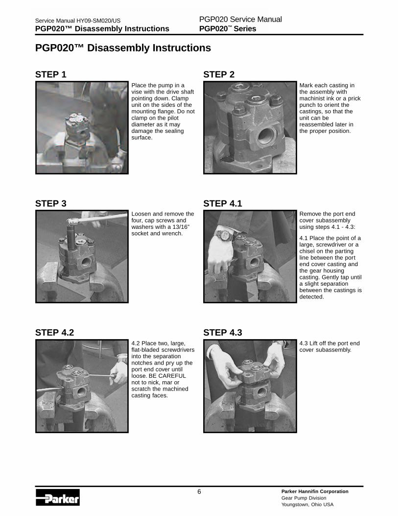
Place the pump in avise with the drive shaftpointing down. Clampunit on the sides of themounting flange. Do notclamp on the pilotdiameter as it maydamage the sealingsurface.
Mark each casting inthe assembly withmachinist ink or a prickpunch to orient thecastings, so that theunit can bereassembled later inthe proper position.
Loosen and remove thefour, cap screws andwashers with a 13/16”socket and wrench.
Remove the port endcover subassemblyusing steps 4.1 - 4.3:
4.1 Place the point of alarge, screwdriver or achisel on the partingline between the portend cover casting andthe gear housingcasting. Gently tap untila slight separationbetween the castings isdetected.
4.2 Place two, large,flat-bladed screwdriversinto the separationnotches and pry up theport end cover untilloose. BE CAREFULnot to nick, mar orscratch the machinedcasting faces.
4.3 Lift off the port endcover subassembly.
STEP 1 STEP 2
STEP 3 STEP 4.1
STEP 4.2 STEP 4.3
PGP020™ Disassembly Instructions
Parker Hannifin CorporationGear Pump DivisionYoungstown, Ohio USA
7
Service Manual HY09-SM020/US
PGP020™ Disassembly InstructionsPGP020 Service ManualPGP020™ Series
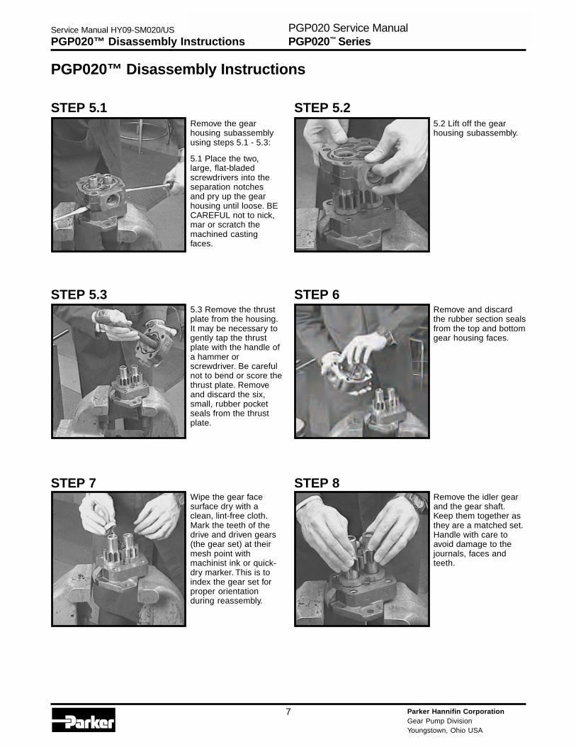
Remove the gearhousing subassemblyusing steps 5.1 - 5.3:
5.1 Place the two,large, flat-bladedscrewdrivers into theseparation notchesand pry up the gearhousing until loose. BECAREFUL not to nick,mar or scratch themachined castingfaces.
5.2 Lift off the gearhousing subassembly.
5.3 Remove the thrustplate from the housing.It may be necessary togently tap the thrustplate with the handle ofa hammer orscrewdriver. Be carefulnot to bend or score thethrust plate. Removeand discard the six,small, rubber pocketseals from the thrustplate.
Remove and discardthe rubber section sealsfrom the top and bottomgear housing faces.
Wipe the gear facesurface dry with aclean, lint-free cloth.Mark the teeth of thedrive and driven gears(the gear set) at theirmesh point withmachinist ink or quick-dry marker. This is toindex the gear set forproper orientationduring reassembly.
Remove the idler gearand the gear shaft.Keep them together asthey are a matched set.Handle with care toavoid damage to thejournals, faces andteeth.
STEP 5.1 STEP 5.2
STEP 5.3 STEP 6
STEP 7 STEP 8
PGP020™ Disassembly Instructions
Parker Hannifin CorporationGear Pump DivisionYoungstown, Ohio USA
8
Service Manual HY09-SM020/US
PGP020™ Disassembly InstructionsPGP020 Service ManualPGP020™ Series
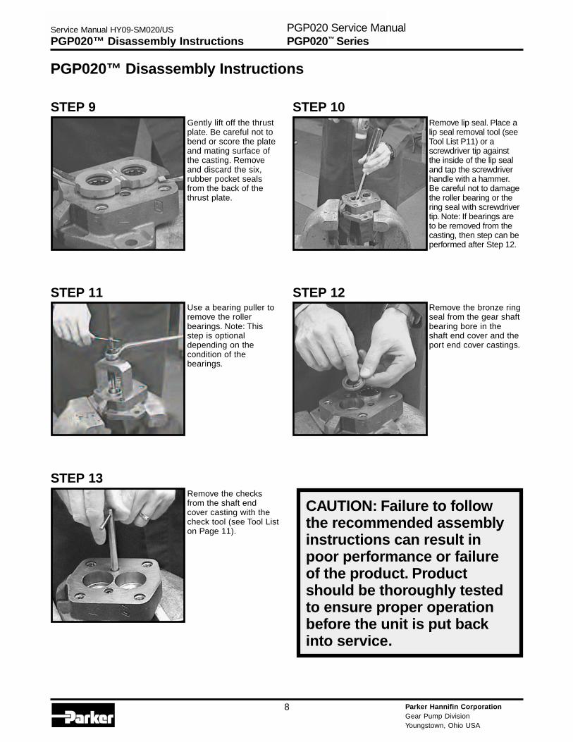
Gently lift off the thrustplate. Be careful not tobend or score the plateand mating surface ofthe casting. Removeand discard the six,rubber pocket sealsfrom the back of thethrust plate.
Remove lip seal. Place alip seal removal tool (seeTool List P11) or ascrewdriver tip againstthe inside of the lip sealand tap the screwdriverhandle with a hammer.Be careful not to damagethe roller bearing or thering seal with screwdrivertip. Note: If bearings areto be removed from thecasting, then step can beperformed after Step 12.
Use a bearing puller toremove the rollerbearings. Note: Thisstep is optionaldepending on thecondition of thebearings.
Remove the bronze ringseal from the gear shaftbearing bore in theshaft end cover and theport end cover castings.
Remove the checksfrom the shaft endcover casting with thecheck tool (see Tool Liston Page 11).
CAUTION: Failure to followthe recommended assemblyinstructions can result inpoor performance or failureof the product. Productshould be thoroughly testedto ensure proper operationbefore the unit is put backinto service.
STEP 9 STEP 10
STEP 11 STEP 12
STEP 13
PGP020™ Disassembly Instructions

Parker Hannifin CorporationGear Pump DivisionYoungstown, Ohio USA
9
Service Manual HY09-SM020/US
PGP020™ Assembly InstructionsPGP020 Service ManualPGP020™ Series
Stone all machinedcasting surfaces with amedium-gritcarborundum stone. Ifthe bearings wereremoved, deburr thebearing bore using adeburring tool. Rinse allparts in a solvent fluid.Air blast all parts andwipe them with a clean,lint-free cloth beforestarting the assembly.
Coat the outsidediameter of the lip sealwith Permatex AviationForm-A-Gasket No.3Non-Hardening Sealantor equivalent. Becareful not to getPermatex on the innerlip of the seal as it willcause a lip seal leak.
Place the shaft end coveron an arbor press withthe pilot facing up. Placelip seal with the shoulderof the seal up, at the topof the seal bore. Pressthe lip seal into the shaftend cover with a lip sealinstallation bar (see ToolList on Page 11). Theseal should be pressedin so it is flush with therecessed face in theshaft end cover casting.
Apply Loctite® No.262to the threaded checkholes in the shaft endcasting. Install thechecks in the shaft endcover using the checktool (see Tool List onPage 11). The checksmust bottom out inthe casting.
Peen over the checkholes in the shaft endcover with a 1½” steelball and a hammer.This will insure thechecks do not back outof the check holesduring operation.
If the ring seals wereremoved from the shaftend cover or the portend cover, they shouldbe replaced at this time.Place the ring seals inthe bottom of the drivegear bearing bores. Besure that the flat side ofthe ring seal is againstthe mating surface in thecasting. Ring seals areplaced behind the drivegear bearings only.
STEP 1 STEP 2
STEP 3 STEP 4
STEP 5 STEP 6
PGP020™ Assembly Instructions
Parker Hannifin CorporationGear Pump DivisionYoungstown, Ohio USA
10
Service Manual HY09-SM020/US
PGP020™ Assembly InstructionsPGP020 Service ManualPGP020™ Series
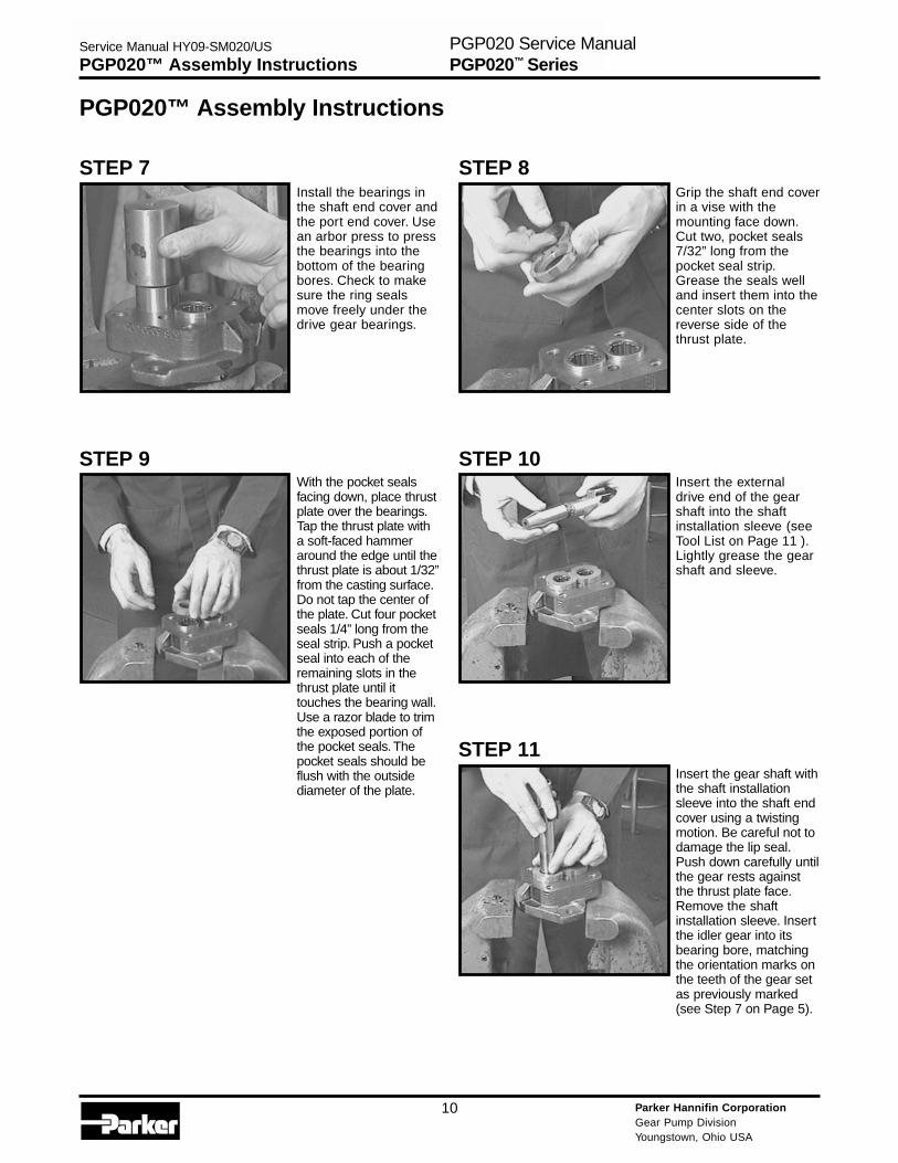
Install the bearings inthe shaft end cover andthe port end cover. Usean arbor press to pressthe bearings into thebottom of the bearingbores. Check to makesure the ring sealsmove freely under thedrive gear bearings.
Grip the shaft end coverin a vise with themounting face down.Cut two, pocket seals7/32” long from thepocket seal strip.Grease the seals welland insert them into thecenter slots on thereverse side of thethrust plate.
With the pocket sealsfacing down, place thrustplate over the bearings.Tap the thrust plate witha soft-faced hammeraround the edge until thethrust plate is about 1/32”from the casting surface.Do not tap the center ofthe plate. Cut four pocketseals 1/4” long from theseal strip. Push a pocketseal into each of theremaining slots in thethrust plate until ittouches the bearing wall.Use a razor blade to trimthe exposed portion ofthe pocket seals. Thepocket seals should beflush with the outsidediameter of the plate.
Insert the externaldrive end of the gearshaft into the shaftinstallation sleeve (seeTool List on Page 11 ).Lightly grease the gearshaft and sleeve.
Insert the gear shaft withthe shaft installationsleeve into the shaft endcover using a twistingmotion. Be careful not todamage the lip seal.Push down carefully untilthe gear rests againstthe thrust plate face.Remove the shaftinstallation sleeve. Insertthe idler gear into itsbearing bore, matchingthe orientation marks onthe teeth of the gear setas previously marked(see Step 7 on Page 5).
STEP 7 STEP 8
STEP 9 STEP 10
STEP 11
PGP020™ Assembly Instructions

Parker Hannifin CorporationGear Pump DivisionYoungstown, Ohio USA
11
Service Manual HY09-SM020/US
PGP020™ Assembly InstructionsPGP020 Service ManualPGP020™ Series
Apply a light coating ofgrease to the newsection seals and placethem into the machinedgrooves on both sidesof the gear housing.Check the section sealsfor proper fit.
Locate the orientationmark on the gearhousing and line it upwith the mark on theshaft end cover. Slide thegear housing over gearset. Make sure the gearhousing rests tightlyagainst shaft end cover.Be careful not to pinchthe section seal. Squirtclean, hydraulic oil overthe gear shaft and theidler gear to provide initiallubrication when thepump is started.
Insert the pocket sealsinto the thrust plate andinstall onto the port endcover following theprevious instructions insteps 8 & 9. Then placeport end cover over thegear journals. Theorientation mark on portend cover must line upwith the mark on the gearhousing. Also, be surebearing bore holding thering seal goes over thedrive gear journal. Applypressure to the castingwith your hand or taplightly with a soft-facedhammer until the portend cover rests tightlyagainst the gear housing.
Thread the four, capscrews with thewashers into the shaftend cover and tightenthem in a cross-cornerpattern. Rotate the gearshaft of the pump with a6” wrench to makecertain there is nobinding in the pump.
After the cap screwsare tightened, makecertain there is nointernal binding of thegear set by rotatingthe gear shaft, thentighten the cap screwsin a cross-cornerpattern to a finaltorque of 2400 in. lbs.(200 ft. lbs.).
STEP 12 STEP 13
STEP 14 STEP 15
STEP 16
PGP020™ Assembly Instructions
Parker Hannifin CorporationGear Pump DivisionYoungstown, Ohio USA
12
Service Manual HY09-SM020/US
Part Replacement GuidePGP020 Service ManualPGP020™ Series
Part Replacement Guide
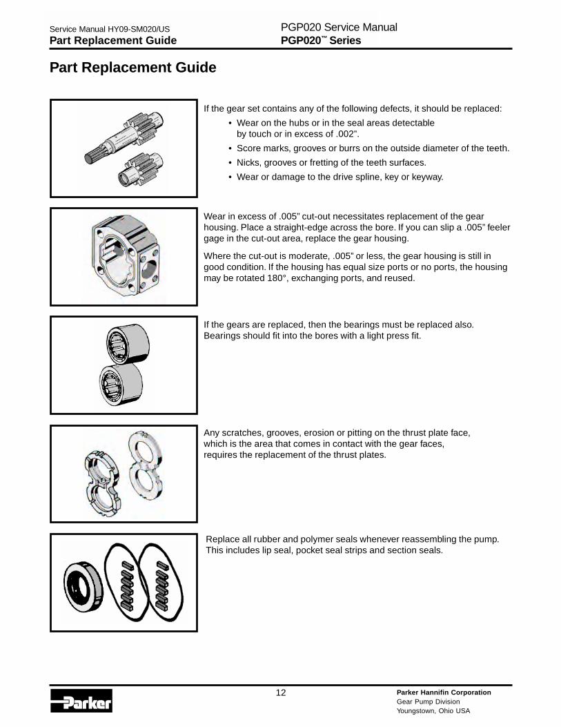
If the gear set contains any of the following defects, it should be replaced:
• Wear on the hubs or in the seal areas detectableby touch or in excess of .002”.
• Score marks, grooves or burrs on the outside diameter of the teeth.
• Nicks, grooves or fretting of the teeth surfaces.
• Wear or damage to the drive spline, key or keyway.
Wear in excess of .005” cut-out necessitates replacement of the gearhousing. Place a straight-edge across the bore. If you can slip a .005” feelergage in the cut-out area, replace the gear housing.
Where the cut-out is moderate, .005” or less, the gear housing is still ingood condition. If the housing has equal size ports or no ports, the housingmay be rotated 180°, exchanging ports, and reused.
If the gears are replaced, then the bearings must be replaced also.Bearings should fit into the bores with a light press fit.
Any scratches, grooves, erosion or pitting on the thrust plate face,which is the area that comes in contact with the gear faces,requires the replacement of the thrust plates.
Replace all rubber and polymer seals whenever reassembling the pump.This includes lip seal, pocket seal strips and section seals.
Parker Hannifin CorporationGear Pump DivisionYoungstown, Ohio USA
13
Service Manual HY09-SM020/US
Tool ListPGP020 Service ManualPGP020™ Series
Tool List
• Arbor press• Permanent marker or an awl• Bearing puller
(Owatonna Tool Co.MD-956 or equivalent)
• Clean, lint-free cloths• Deburring tool (a file with the
cutting teeth ground off)• Machinist hammer• Soft-faced hammer• Permatex Aviation Form-A-Gasket
No.3 Non-hardening Sealant or equivalent• Medium-grit carborundum stone• Hydraulic oil and grease• Prick punch or machinists ink• Sharp, razor blade• Scale (1/32” or 1/64” graduations)• Feeler gauges• Small, flat-head screwdriver• Large, flat-headed screwdrivers• Torque wrench• 13/16” socket• 1½” steel ball• Loctite® No.262• Vise with a 6” minimum open spread• Lip seal installation bar (1 3/4” X 2”)• Shaft installation sleeve (steel)• Lip seal removal tool• Check tool• 6” wrench
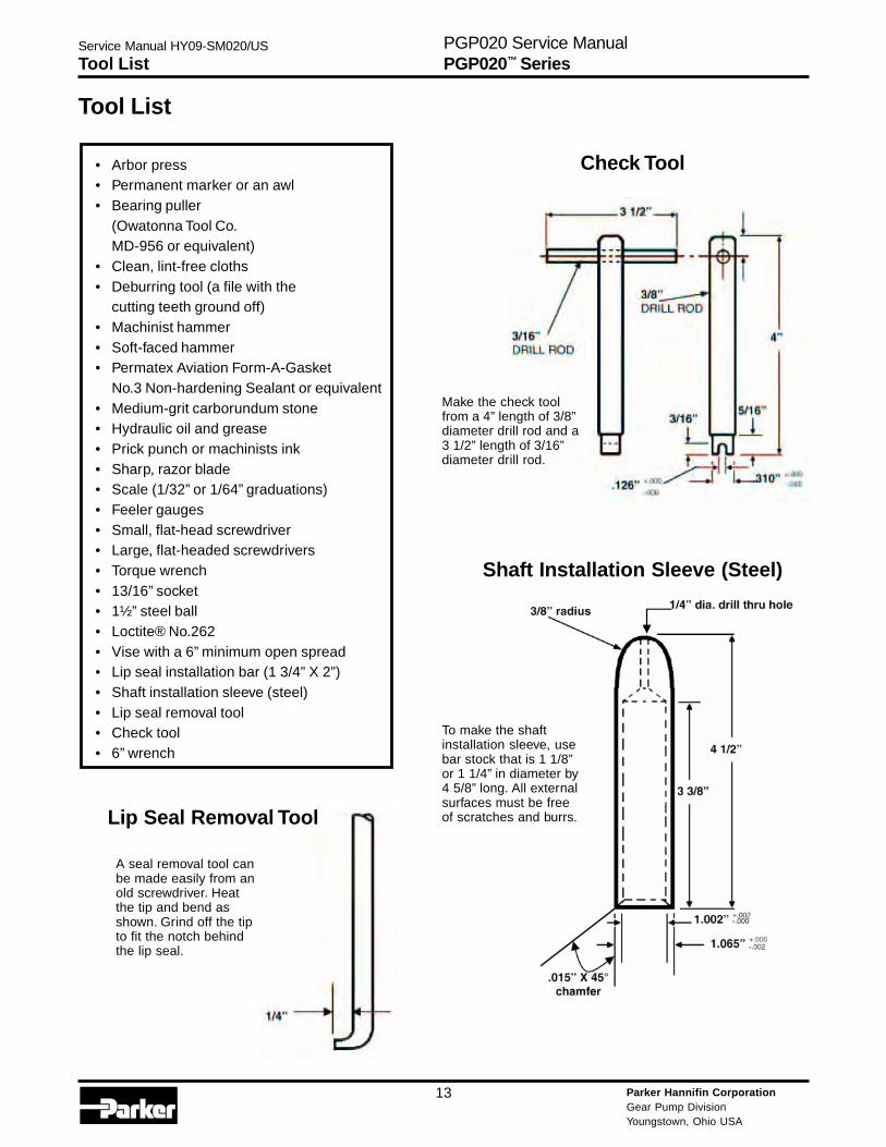
Make the check toolfrom a 4” length of 3/8”diameter drill rod and a3 1/2” length of 3/16”diameter drill rod.
To make the shaftinstallation sleeve, usebar stock that is 1 1/8”or 1 1/4” in diameter by4 5/8” long. All externalsurfaces must be freeof scratches and burrs.
A seal removal tool canbe made easily from anold screwdriver. Heatthe tip and bend asshown. Grind off the tipto fit the notch behindthe lip seal.
Lip Seal Removal Tool
Check Tool
Shaft Installation Sleeve (Steel)
Parker Hannifin CorporationGear Pump DivisionYoungstown, Ohio USA
14
Service Manual HY09-SM020/US
Lubrication/Oil RecommendationsPGP020 Service ManualPGP020™ Series
Lubrication and Oil RecommendationsAll parts, with the exception of the outboard bearing, are lubricated by the hydraulic oil in the circuit. Particularattention must be paid to keep the oil in the system clean. Whenever there is a pump or motor failure and there isreason to suspect that metal particles may be in the system, the oil must be drained, the entire system flushedclean and any filter screens thoroughly cleaned or replaced. New oil should be supplied for the entire system. Oilsuitable and recommended for use in circuits involving Commercial Hydraulics’ pumps and motors should meetthe following specifications:
Viscosity: • 50 SSU minimum @ operating temperature7500 SSU maximum @ starting temperature
• 150 to 225 SSU @ 100º F (37.8º C) (generally)44 to 48 SSU @ 210º F (98.9º C) (generally)
Viscosity Index: 90 minimum
Aniline Point: 175 minimum
Recommended Additives: Foam DepressantRust and Oxidation Inhibitors
Other Desirable Characteristics: • Stability of physical and chemical characteristics.
• High demulsibility (low emulsibility) for separationof water, air and contaminants.
• Resistant to the formation of gums, sludges, acids, tars and varnishes.
• High lubricity and film strength.
General Recommendations:
A good-quality, hydraulic oil conforming to the characteristics listed above is essential to the satisfactoryperformance and long life of any hydraulic system.
Oil should be changed on a regular schedule in accordance with the equipment manufacturer’srecommendations, and the system should be periodically flushed.
Oil temperature in reservoir must not exceed 200º F (93.3º C) with a maximum temperature of 180º F (82.2º C)recommended. Higher temperatures will result in rapid oil deterioration.
Reservoir capacity should equal in gallons the pump output in gpm or the total gpm of all pumps where there ismore than one in the system.
Normal Temperatures: 0º F (-18º C) to 100º F (37.8º C) Ambient
100º F (37.8º C) to 180º F (82.2º C) System
Be sure your oil is suitable for the temperatures you expect to encounter.
Cold Weather Operation:
Oils for use in cold weather should have a viscosity that does not exceed 7500 SSU at the minimum start-uptemperature. A pour point of at least 20º F below start-up temperature is recommended. Start-up proceduresshould allow for a gradual warm-up until the oil reaches a reasonably fluid state.
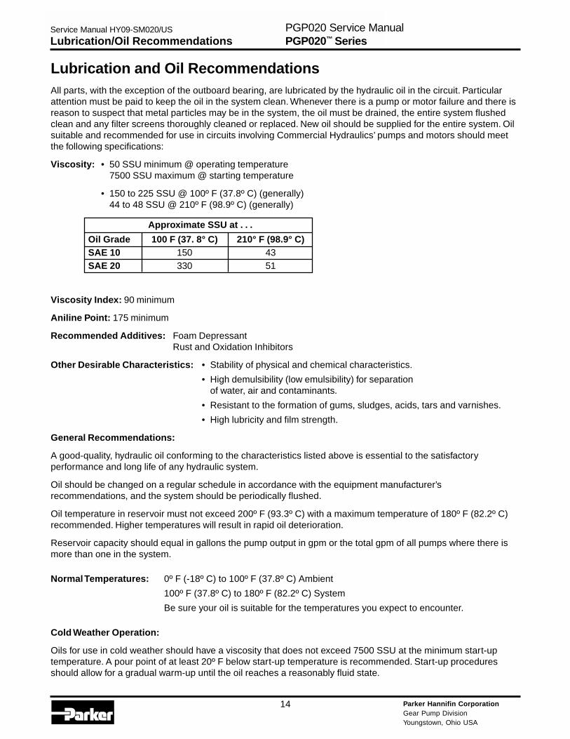
Approximate SSU at . . .
Oil Grade 100 F (37. 8° C) 210° F (98.9° C)SAE 10 150 43SAE 20 330 51
Parker Hannifin CorporationGear Pump DivisionYoungstown, Ohio USA
15
Service Manual HY09-SM020/US
Lubrication/Oil RecommendationsPGP020 Service ManualPGP020™ Series
Lubrication and Oil RecommendationsThe Use of Other Oils:
• Diesel Fuel or Kerosene (Coal Oil): These are sometimes used as dilutants for cold weather operations butare not recommended as they are not sufficiently refined products.
• Fire-Resistant Fluids: Of the several different types, only the inverted emulsion types may be used withoutswitching to a special seal, packing, gasket, hose, etc., compositions. Their use may substantially reducepump life. Experience indicates that the use of fire-resistant fluids can be disastrous unless certainprecautions are followed. DO NOT USE ANY FIRE RESISTANT FLUIDS OR NON-PETROLEUM OILSWITHOUT CONSULTING OUR PRODUCT SUPPORT DEPARTMENT.
• These suggestions are intended as a guide only. OBTAIN YOUR FINAL OIL RECOMMENDATIONS FROMYOUR OIL SUPPLIER.
Parker Hannifin CorporationGear Pump DivisionYoungstown, Ohio USA
16
Service Manual HY09-SM020/US
Reccomended Start-up ProcedurePGP020 Service ManualPGP020™ Series
Recommended Start-up Procedurefor New or Rebuilt Pump or MotorBefore installing a new or a rebuilt pump or motor, back out the main relief valve until the spring tension on theadjusting screw is relaxed. This will avoid the possibility of immediate damage to the replacement unit in the eventthat the relief valve setting had been increased beyond the recommended operating pressure prior to removingthe old unit.
Before connecting any lines to the pump or to the motor, fill all ports with clean oil to provide initial lubrication. Thisis particularly important when the unit is located above the oil reservoir.
After connecting the lines and mounting the replacement unit, operate the pump or the motor for at least twominutes at zero pressure at the lowest possible rpm. During this break-in period, the unit should run free and notdevelop an excessive amount of heat. If the unit operates properly, the speed and the pressure can then beincreased to the normal operating settings.
Reset the main relief valve to its proper setting while the pump is running at the maximum operating engine(motor) speed for the vehicle.
ALWAYS USE AN ACCURATE GAGE WHEN ADJUSTING THERELIEF VALVE PRESSURE SETTING.
Parker Hannifin CorporationGear Pump DivisionYoungstown, Ohio USA
17
Service Manual HY09-SM020/US
Test Procedure RecommendedPGP020 Service ManualPGP020™ Series
Test Procedure Recommended
At test speeds other than 1800 rpm, gpm delivery willvary almost proportionately, but the same (drop-off)figures should be used.
Be sure to run the pump in the direction for which itwas designed and built. Driving the pump in the wrongdirection will build up pressure behind the lip seal,causing damage to the pump and necessitating itsreplacement.
Be sure there is an adequate supply of oil for thepump; at least one gallon of oil for each gpm of pumpcapacity.
If one section of a tandem pump is being tested, makesure all other sections which are not being tested, areadequately supplied with oil. If any of the other sectionsrun dry or if plugs are left in ports, serious andpermanent damage will result.
The oil should be a good-quality, hydraulic oil rated at150 SSU at 100º F with the oil temperature held at120º F plus or minus 5º F. (Test procedures aredescribed in detail in SAE handbooks; see HydraulicPower Pump Test Procedure SAE J745c.)
The inlet line must be an adequate size with no morethan 5” mercury vacuum adjacent to the pump inlet. Asa rule, the inlet line must provide an inlet flow velocitythat is not in excess of 8 feet per second.
Hot oil drawn into a cold pump could cause it to seize.Switching the pump on and off in short bursts couldhelp prevent seizure.
Operate the pump at least two minutes at zeropressure and at moderate speed (not over 1500 rpm).
If pump becomes hot to touch, it is binding and couldseize. This rarely occurs, but if it does, the pump will
have to be disassembled and be rebuilt, taking extracare to remove burrs and to assure freedom frombinding.
Gradually increase the pressure on a pump until thedesired test pressure has been reached. This shouldtake about five minutes.
Delivery should run close to the rated, catalogperformance figures which are averaged from thetesting of several pumps. A 5% lower reading may beused as a rated minimum, if new or relatively new partshave been used. When rebuilding the pump, reuse onlythose parts which appear to be in satisfactorycondition. A 10% or 15% lower reading is permitted forthe rebuilt pump, depending upon the performanceexpected from the equipment. Your individualexperience is the best guide.
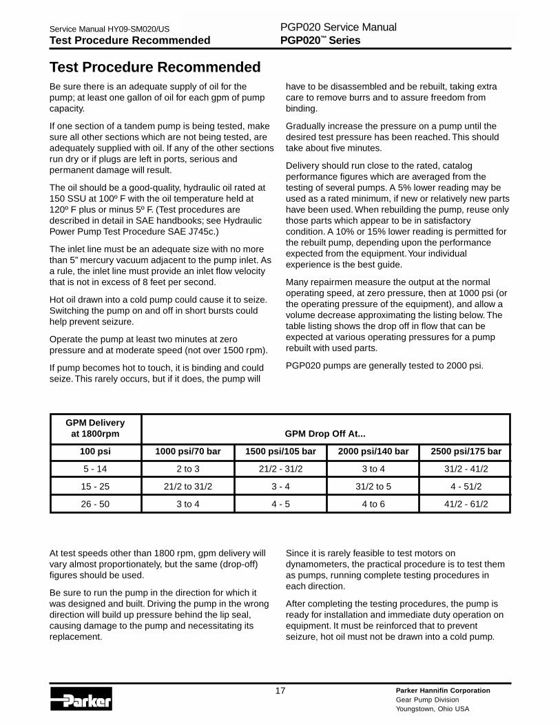
Many repairmen measure the output at the normaloperating speed, at zero pressure, then at 1000 psi (orthe operating pressure of the equipment), and allow avolume decrease approximating the listing below. Thetable listing shows the drop off in flow that can beexpected at various operating pressures for a pumprebuilt with used parts.
PGP020 pumps are generally tested to 2000 psi.
Since it is rarely feasible to test motors ondynamometers, the practical procedure is to test themas pumps, running complete testing procedures ineach direction.
After completing the testing procedures, the pump isready for installation and immediate duty operation onequipment. It must be reinforced that to preventseizure, hot oil must not be drawn into a cold pump.
GPM Deliveryat 1800rpm GPM Drop Off At...
100 psi 1000 psi/70 bar 1500 psi/105 bar 2000 psi/140 bar 2500 psi/175 bar
5 - 14 2 to 3 21/2 - 31/2 3 to 4 31/2 - 41/2
15 - 25 21/2 to 31/2 3 - 4 31/2 to 5 4 - 51/2
26 - 50 3 to 4 4 - 5 4 to 6 41/2 - 61/2
Parker Hannifin CorporationGear Pump DivisionYoungstown, Ohio USA
18
Service Manual HY09-SM020/US
Instructions for Change of RotationPGP020 Service ManualPGP020™ Series
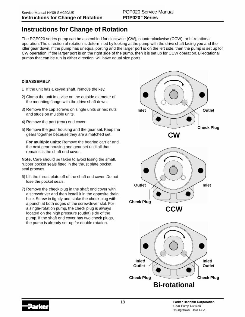
Outlet
Check Plug
Inlet
CW
Inlet
Check Plug
Outlet
CCW
Inlet/Outlet
Inlet/Outlet
Bi-rotationalCheck Plug Check Plug
Instructions for Change of RotationThe PGP020 series pump can be assembled for clockwise (CW), counterclockwise (CCW), or bi-rotationaloperation. The direction of rotation is determined by looking at the pump with the drive shaft facing you and theidler gear down. If the pump has unequal porting and the larger port is on the left side, then the pump is set up forCW operation. If the larger port is on the right side of the pump, then it is set up for CCW operation. Bi-rotationalpumps that can be run in either direction, will have equal size ports.
DISASSEMBLY
1 If the unit has a keyed shaft, remove the key.
2) Clamp the unit in a vise on the outside diameter ofthe mounting flange with the drive shaft down.
3) Remove the cap screws on single units or hex nutsand studs on multiple units.
4) Remove the port (rear) end cover.
5) Remove the gear housing and the gear set. Keep thegears together because they are a matched set.
For multiple units: Remove the bearing carrier andthe next gear housing and gear set until all thatremains is the shaft end cover.
Note: Care should be taken to avoid losing the small,rubber pocket seals fitted in the thrust plate pocketseal grooves.
6) Lift the thrust plate off of the shaft end cover. Do notlose the pocket seals.
7) Remove the check plug in the shaft end cover witha screwdriver and then install it in the opposite drainhole. Screw in tightly and stake the check plug witha punch at both edges of the screwdriver slot. Fora single-rotation pump, the check plug is alwayslocated on the high pressure (outlet) side of thepump. If the shaft end cover has two check plugs,the pump is already set-up for double rotation.
Parker Hannifin CorporationGear Pump DivisionYoungstown, Ohio USA
19
Service Manual HY09-SM020/US
Instructions for Change of Rotation
ASSEMBLY
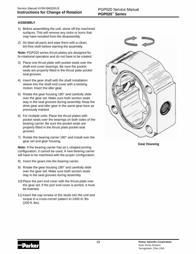
1) Before assembling the unit, stone off the machinedsurfaces. This will remove any nicks or burrs thatmay have resulted from the disassembly.
2) Air blast all parts and wipe them with a clean,lint-free cloth before starting the assembly.
Note: PGP020 series thrust plates are designed forbi-rotational operation and do not have to be rotated.
3) Place one thrust plate with pocket seals over theshaft end cover bearings. Be sure the pocketseals are properly fitted in the thrust plate pocketseal grooves.
4) Insert the gear shaft with the shaft installationsleeve into the shaft end cover with a twistingmotion. Insert the idler gear.
5) Rotate the gear housing 180° and carefully slideover the gear set. Make sure both section sealsstay in the seal grooves during assembly. Keep thedrive gear and idler gear in the same gear bore aspreviously marked.
6) For multiple units: Place the thrust plates withpocket seals over the bearings on both sides of thebearing carrier. Be sure the pocket seals areproperly fitted in the thrust plate pocket sealgrooves.
7) Rotate the bearing carrier 180° and install over thegear set and gear housing.
Note: If the bearing carrier has an L-shaped portingconfiguration, it cannot be used. A new bearing carrierwill have to be machined with the proper configuration.
8) Insert the gears into the bearing carrier.
9) Rotate the gear housing 180° and carefully slideover the gear set. Make sure both section sealsstay in the seal grooves during assembly.
10) Place the port end cover with the thrust plate overthe gear set. If the port end cover is ported, it mustbe inverted.
11) Insert the cap screws or the studs into the unit andtorque in a cross-corner pattern to 2400 in. lbs(200 ft. lbs).
PGP020 Service ManualPGP020™ Series
Gear Housing

Parker Hannifin CorporationGear Pump DivisionYoungstown, Ohio USA
20
Notes

Parker Hannifin CorporationGear Pump DivisionYoungstown, Ohio USA
21
Notes
Parker Hannifin CorporationGear Pump DivisionYoungstown, Ohio USA
22
The items described in this document are hereby offered for sale at prices to be established by Parker Hannifin Corporation, its subsidiaries and itsauthorized distributors. This offer and its acceptance by any customer (“Buyer”) shall be governed by all of the following Terms and Conditions. Buyer’s orderfor any item described in its document, when communicated to Parker Hannifin Corporation, its subsidiary or an authorized distributor (“Seller”) verbally or inwriting, shall constitute acceptance of this offer.
1. Terms and Conditions of Sale: All descriptions, quotations, proposals,offers, acknowledgments, acceptances and sales of Seller’s products aresubject to and shall be governed exclusively by the terms and conditionsstated herein. Buyer’s acceptance of any offer to sell is limited to these termsand conditions. Any terms or conditions in addition to, or inconsistent withthose stated herein, proposed by Buyer in any acceptance of an offer bySeller, are hereby objected to. No such additional, different or inconsistentterms and conditions shall become part of the contract between Buyer andSeller unless expressly accepted in writing by Seller. Seller’s acceptance ofany offer to purchase by Buyer is expressly conditional upon Buyer’s assentto all the terms and conditions stated herein, including any terms in additionto, or inconsistent with those contained in Buyer’s offer. Acceptance ofSeller’s products shall in all events constitute such assent.
2. Payment: Payment shall be made by Buyer net 30 days from the dateof delivery of the items purchased hereunder. Any claims by Buyer foromissions or shortages in a shipment shall be waived unless Seller receivesnotice thereof within 30 days after Buyer’s receipt of the shipment.
3. Delivery: Unless otherwise provided on the face hereof, delivery shall bemade F.O.B. Seller’s plant. Regardless of the method of delivery, however,risk of loss shall pass to Buyer upon Seller’s delivery to a carrier. Anydelivery dates shown are approximate only and Seller shall have no liabilityfor any delays in delivery.
4. Warranty: Seller warrants that the item sold hereunder shall be free fromdefects in material or workmanship for a period of 547 days from the date ofshipment to Buyer, or 3,000 hours of use, whichever expires first. THISWARRANTY COMPRISES THE SOLE AND ENTIRE WARRANTYPERTAINING TO ITEMS PROVIDED HEREUNDER. SELLER MAKES NOOTHER WARRANTY, GUARANTEE, OR REPRESENTATION OF ANYKIND WHATSOEVER. ALL OTHER WARRANTIES, INCLUDING BUT NOTLIMITED TO, MERCHANTABILITY AND FITNESS FOR PURPOSE,WHETHER EXPRESS, IMPLIED, OR ARISING BY OPERATION OF LAW,TRADE USAGE, OR COURSE OF DEALING ARE HEREBY DISCLAIMED.
NOTWITHSTANDING THE FOREGOING, THERE ARE NO WARRANTIESWHATSOEVER ON ITEMS BUILT OR ACQUIRED WHOLLY OR PAR-TIALLY, TO BUYERS DESIGNS OR SPECIFICATIONS.
5. Limitation of Remedy: SELLER’S LIABILITY ARISING FROM OR INANY WAY CONNECTED WITH THE ITEMS SOLD OR THIS CONTRACTSHALL BE LIMITED EXCLUSIVELY TO REPAIR OR REPLACEMENT OFTHE ITEMS SOLD OR REFUND OF THE PURCHASE PRICE PAID BYBUYER, AT SELLER’S SOLE OPTION IN NO EVENT SHALL SELLER BELIABLE FOR ANY INCIDENTAL OR SEQUENTIAL OR SPECIALDAMAGES OF ANY KIND OR NATURE WHATSOEVER, INCLUDING BUTNOT LIMITED TO LOST PROFITS ARISING FROM OR IN ANY WAYCONNECTED WITH THIS AGREEMENT OR ITEM SOLD HEREUNDER,WHETHER ALLEGED TO ARISE FROM BREACH OF CONTRACT,EXPRESS OR IMPLIED WARRANTY, OR IN TORT, INCLUDING WITHOUTLIMITATION, NEGLIGENCE, FAILURE TO WARN OR STRICT LIABILITY.
6. Changes, Reschedules and Cancellations: Buyer may request to modifythe designs or specifications for the items sold hereunder as well as thequantities and delivery dates thereof, or may request to cancel all or part ofthis order, however, no such requested modification or cancellation shallbecome part of the contract between Buyer and Seller unless accepted bySeller in a written amendment to this Agreement. Acceptance of any suchrequested modification or cancellation shall be at Seller’s discretion, andshall be upon such terms and conditions as Seller may require.
7. Special Tooling: A tooling charge may be imposed for any special tooling,including without limitation, dies, fixtures, molds and patterns, acquired tomanufacture items sold pursuant to this contract. Such special tooling shallbe and remain Seller’s property notwithstanding payment of any charges byBuyer. In no event will Buyer acquire any interest in apparatus belonging toSeller which is utilized in the manufacture of the items sold hereunder, even ifsuch apparatus has been specially converted or adapted for such manufac-ture and notwithstanding any charges paid by Buyer. Unless otherwiseagreed, Seller shall have the right to alter, discard or otherwise dispose ofany special tooling or other property in its sole discretion at any time.
8. Buyer’s Property: Any designs, tools, patterns, materials, drawings,confidential information or equipment furnished by Buyer or any other itemswhich become Buyer’s property, may be considered obsolete and may bedestroyed by Seller after two (2) consecutive years have elapsed withoutBuyer placing an order for the items which are manufactured using suchproperty. Seller shall not be responsible for any loss or damage to suchproperty while it is in Seller’s possession or control.
9. Taxes: Unless otherwise indicated on the face hereof, all prices andcharges are exclusive of excise, sales, use, property, occupational or liketaxes which may be imposed by any taxing authority upon the manufacture,sale or delivery of the items sold hereunder. If any such taxes must be paidby Seller or if Seller is liable for the collection of such tax, the amount thereofshall be in addition to the amounts for the items sold. Buyer agrees to pay allsuch taxes or to reimburse Seller therefore upon receipt of its invoice. IfBuyer claims exemption from any sales, use or other tax imposed by anytaxing authority, Buyer shall save Seller harmless from and against any suchtax, together with any interest or penalties thereon which may be assessed ifthe items are held to be taxable.
10. Indemnity For Infringement of Intellectual Property Rights: Sellershall have no liability for infringement of any patents, trademarks, copyrights,trade dress, trade secrets or similar rights except as provided in this Part 10.Seller will defend and indemnify Buyer against allegations of infringement ofU.S. patents, U.S. trademarks, copyrights, trade dress and trade secrets(hereinafter ‘Intellectual Property Rights’). Seller will defend at its expenseand will pay the cost of any settlement or damages awarded in an actionbrought against Buyer based on an allegation that an item sold pursuant tothis contract infringes the Intellectual Property Rights of a third party. Seller’sobligation to defend and indemnify Buyer is contingent on Buyer notifyingSeller within ten (10) days after Buyer becomes aware of such allegations ofinfringement, and Seller having sole control over the defense of anyallegations or actions including all negotiations for settlement or compromise.If an item sold hereunder is subject to a claim that it infringes the IntellectualProperty Rights of a third party, Seller may, at its sole expense and option,procure for Buyer the right to continue using said item, replace or modify saidtime so as to make it noninfringing, or offer to accept return of said item andreturn the purchase price less a reasonable allowance for depreciation.Notwithstanding the foregoing Seller shall have no liability for claims ofinfringement based on information provided by Buyer, or directed to itemsdelivered hereunder for which the designs are specified in whole or part byBuyer, or infringements resulting from the modification, combination or use ina system of any item sold hereunder. The foregoing provisions of this Part 10shall constitute Seller’s sole and exclusive liability and Buyer’s sole andexclusive remedy for infringement of Intellectual Property Rights.
If a claim is based on information provided by Buyer or if the design for anitem delivered hereunder is specified in whole or in part by Buyer, Buyer shalldefend and indemnify Seller for all costs, expenses or judgments resultingfrom any claim that such item infringes any patent, trademark, copyright,trade dress, trade secret or any similar right.
11. Force Majeure: Seller does not assume the risk of and shall not beliable for delay or failure to perform any of Seller’s obligations by reason ofcircumstances beyond the reasonable control of Seller (hereinafter ‘Eventsof Force Majeure’). Events of Force Majeure shall include without limitation,accidents, acts of God, strikes or labor disputes, acts, laws, rules orregulations of any government or government agency, fires, floods, delaysor failures in delivery of carriers or suppliers, shortages of materials andany other cause beyond Seller’s control.
12. Entire Agreement/Governing Law: The terms and conditions set forthherein, together with any amendments, modifications and any different termsor conditions expressly accepted by Seller in writing, shall constitute theentire Agreement concerning the items sold, and there are no oral or otherrepresentations or agreements which pertain thereto. This Agreement shallbe governed in all respects by the law of the State of Ohio. No actions arisingout of the sale of the items sold hereunder or this Agreement may be broughtby either party more than two (2) years after the cause of action accrues.
Offer of Sale
Parker Hannifin CorporationGear Pump DivisionYoungstown, Ohio USA
23
The Aerospace Groupis a leader in the development,design, manufacture andservicing of control systemsand components for aerospaceand related high-technologymarkets, while achievinggrowth through premiercustomer service.
The Fluid ConnectorsGroup designs, manufacturesand markets rigid and flexibleconnectors, and associatedproducts used in pneumaticand fluid systems.
The Hydraulics Groupdesigns, produces andmarkets a full spectrumof hydraulic compnentsand systems to buildersand users of industrialand mobile machineryand equipment.
The Automation Groupis a leading supplier ofpneu-matic and electro-mechanical componentsand systems to automationcustomers worldwide.
The Climate & IndustrialControls Groupdesigns, manufactures andmarkets system-control andfluid-handling componentsand systems to refrigeration,air-conditioning and industrialcustomers worldwide.
The Seal Group designs,manufactures and distributesindustrial and commercialsealing devices and relatedproducts by providingsuperior quality andtotal customer satisfaction.
The Filtration Groupdesigns, manufactures andmarkets quality filtrationand clarification products,providing customers withthe best value, quality,technical support, andglobal availability.
The InstrumentationGroup is a global leaderin the design, manufactureand distribution of high-quality critical flowcomponents for worldwideprocessinstrumentation,ultra-high-purity, medicaland analytical applications.
Parker’s CharterTo be a leading worldwide manufacturer of componentsand systems for the builders and users of durablegoods. More specifically, we will design, market andmanufacture products controlling motion, flow andpressure. We will achieve profitable growth throughpremier customer service.
Product InformationNorth American customers seeking product information,the location of a nearby distributor, or repair serviceswill receive prompt attention by calling the ParkerProduct Information Center at our toll-free number:1-800-C-PARKER (1-800-272-7537). In the UK, a similarservice is available by calling 0500-103-203.
About Parker Hannifin CorporationParker Hannifin is a leading global motion-controlcompany dedicated to delivering premier customerservice. A Fortune 500 corporation listed on theNew York Stock Exchange (PH), our componentsand systems comprise over 1,400 product lines thatcontrol motion in some 1,000 industrial and aerospacemarkets. Parker is the only manufacturer to offer itscustomers a choice of hydraulic, pneumatic, andelectromechanical motion-control solutions. OurCompany has the largest distribution network in itsfield, with over 7,500 distributors serving more than350,000 customers worldwide.
Parker Hannifin Corporation6035 Parkland Blvd.Cleveland, Ohio 44124-4141Telephone: (216) 896-3000Fax: (216) 896-4000Web site: www.parker.com
Parker Hannifin Corporation

Parker Hannifin CorporationGear Pump Division1775 Logan AvenueYoungstown, OH 44501 USATel: (330) 746-8011Fax: (330) 746-1148http://www.parker.com/gearpump
Service ManualHY09-SM020/US2.5M, 07/06, T&M