Embed Size (px)
Citation preview
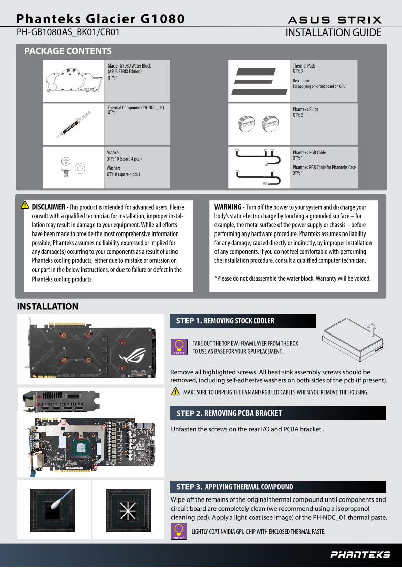
Phanteks Glacier G1080
PACKAGE CONTENTSGlacier G1080 Water Block(ASUS STRIX Edition) QTY: 1
Thermal PadsQTY: 3
Description: For applying on circuit board on GPU
INSTALLATION
STEP 1. REMOVING STOCK COOLER
DISCLAIMER - This product is intended for advanced users. Please -
have been made to provide the most comprehensive information possible, Phanteks assumes no liability expressed or implied for any damage(s) occurring to your components as a result of using Phanteks cooling products, either due to mistake or omission on our part in the below instructions, or due to failure or defect in the Phanteks cooling products.
WARNING - body’s static electric charge by touching a grounded surface – for example, the metal surface of the power supply or chassis – before performing any hardware procedure. Phanteks assumes no liability for any damage, caused directly or indirectly, by improper installation of any components. If you do not feel comfortable with performing
*Please do not disassemble the water block. Warranty will be voided.
STEP 2.
REMOVING PCBA BRACKET
Thermal Compound (PH-NDC_01)QTY: 1
Phanteks PlugsQTY: 2
STEP 3. APPLYING THERMAL COMPOUND
Phanteks RGB CableQTY: 1
PH-GB1080AS_BK01/CR01 INSTALLATION GUIDEASUS STRIX
Remove all highlighted screws. All heat sink assembly screws should be removed, including self-adhesive washers on both sides of the pcb (if present).
Unfasten the screws on the rear I/O and PCBA bracket .
LIGHTLY COAT NVIDIA GPU CHIP WITH ENCLOSED THERMAL PASTE.
Wipe o the remains of the original thermal compound until components and circuit board are completely clean (we recommend using a isopropanol cleaning pad). Apply a light coat (see image) of the PH-NDC_01 thermal paste.
TAKE OUT THE TOP EVA-FOAM LAYER FROM THE BOX TO USE AS BASE FOR YOUR GPU PLACEMENT.
MAKE SURE TO UNPLUG THE FAN AND RGB LED CABLES WHEN YOU REMOVE THE HOUSING.
M2.5x5QTY: 10 (spare 4 pcs.)
WashersQTY: 8 (spare 4 pcs.)
Phanteks RGB Cable for Phanteks CaseQTY: 1

STEP 4. PLACING THERMAL PADS ON PCB
STEP 6. PLACING THE BLOCK ON TO THE GRAPHICS CARD
STEP 5. CONNECTING THE RGB LED
Position 1: 16 x 13 x 1.5mm Position 2: 10 x 90 x 1.5mmPosition 3: 20 x 90 x 1.5mm
f
for V
or memory IC
dd VRM 2
1 1 1 1 1 1 1 1
3for Vdd MOSFET
Place thermal pads on the circuit board as shown on the picture below. Refer to numbering in previous picture when applying thermal pads of different sizes or thickness. Phanteks made sure to provide customers with more than adequate quantity of thermal pads to complete this step.
FOR THERMAL PAD 2 & 3, ADJUST AND CUT LENGTH ACCORDING TO GPU VDD VRM CHIPS.
Make sure to connect the RGB LED cable from the waterblock to the GPU PCB RGB header. (see illustration)
Carefull y position the water block onto the graphics card. During this process please make sure you align mounting holes on the PCB with holes on the water block.
Use the included 6x M2.5x5 screws and washers (shown in blue) to tighten the block to the GPU core.
DO NOT USE TOO MUCH FORCE BY PRESSING THE BLOCK DOWN TO THE PCB. CHIP DIES ARE
MAKE SURE TO LAY THE GPU WITH WATER BLOCK FLAT DOWN WITHOUT RESTING ON THE PCI.
PRONE TO CRACKING.
STEP 7. INSTALLATION OF FITTINGS AND TUBING Screw in the two G1/4 threaded male fittings, attach the liquid cooling tubes and connect the water block(s) into the cooling circuit. Phanteks recommends
Phanteks fittings with the Phanteks Glacier Series water blocks.
DO NOT FORGET TO PLUG THE REMAINING TWO OPENING. FOR BEST PERFORMANCE, WE RECOMMEND TO MATCH THE INLET/OUTLET
using
CONFIGURATION OF THE WATERBLOCK.
115,3066,30
25,30
OUTIN
FOR RGB LED CONTROL (SOFTWARE), PLEASE REFER TO THE USER MANUAL OF YOUR GRAPHIC CARD.
Once the water block is in place, plug in the remaining RGB LED cable connector to the water block as shown in the illustration.
Optional UpgradeSync the lighting with a Phanteks case / RGB Motherboard using the Phanteks upgrade kit (not included).