Embed Size (px)
Citation preview
AnaconAnaconAnaconAnacon Power & ControlsPower & ControlsPower & ControlsPower & Controls Relay Assembly Specialists
An Anacon Electronic Sales, Inc. Company
2254 Main St. Concord, MA 01742 - TEL: 800-466-9080 - 978-287-0715 - FAX: 978-287-0952 www.anaconpower.com email: [email protected]
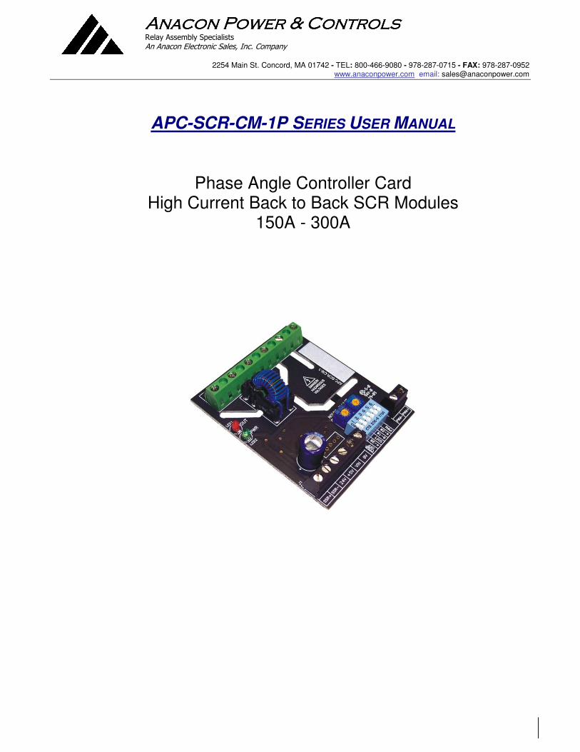
APC-SCR-CM-1P SERIES USER MANUAL
Phase Angle Controller Card High Current Back to Back SCR Modules
150A - 300A

AnaconAnaconAnaconAnacon Power & ControlsPower & ControlsPower & ControlsPower & Controls Relay Assembly Specialists
An Anacon Electronic Sales, Inc. Company
2254 Main St. Concord, MA 01742 - TEL: 800-466-9080 - 978-287-0715 - FAX: 978-287-0952 www.anaconpower.com email: [email protected]
2
TABLE OF CONTENTS
1. Ordering Codes.............................................................................................................................................. 2-3
2. Description .........................................................................................................................................................3
3. Installation / Safety Information..........................................................................................................................3
3.1 Mounting Instructions ................................................................................................................................4
3.2 Electrical Connections...............................................................................................................................4
3.3 SCR Output Snubbers and Transient Protection ......................................................................................4
3.3.1 Commutation Problems ....................................................................................................................4
3.3.2 dv/dt Problems..................................................................................................................................4
3.3.3 Snubber Design ................................................................................................................................4
3.3.4 Snubber Suppliers ............................................................................................................................4
3.3.5 Snubber Sizing..................................................................................................................................4
3.3.6 MOVs and TVSs ...............................................................................................................................4
3.4 Limited Warranty .......................................................................................................................................5
4. Operation ...........................................................................................................................................................5
4.1 Power Supply.............................................................................................................................................5
4.2 24V Power Fusing .....................................................................................................................................5
4.3 Command Input.........................................................................................................................................5
4.4 PWM Command Input...............................................................................................................................5
4.4.1 PWM Input........................................................................................................................................5
4.4.2 Input Fail-safe Protection..................................................................................................................5
4.5 Line Voltage Compensation ......................................................................................................................6
4.5.1 Line Voltage Compensation Nominal Adjustment ............................................................................6
4.6 Soft Start....................................................................................................................................................6
4.7 Voltage Limit..............................................................................................................................................7
4.7.1 Voltage Limit Adjustment Procedure ................................................................................................7
4.8 Configuration Dipswitch.............................................................................................................................7
4.9 SSR Drive Output (APC-SCR-CM-1P- SSR) ............................................................................................8
4.10 Output LED................................................................................................................................................8
4.11 Three Phase Operation .............................................................................................................................8
4.12 Wiring Multiple Units in Single Phase or Three Phase Applications .........................................................8
4.12.1 Connecting Power & Commands In Parallel.....................................................................................9
5. Electrical Specifications .....................................................................................................................................9
6. Mechanical Dimensions ...................................................................................................................................10
7. WIRING DIAGRAM - SINGLE PHASE (SSR OR SCR) ..................................................................................11
8. WIRING DIAGRAM 3 INSIDE DELTA CONNECTION (SSR) .........................................................................12
9. WIRING DIAGRAM 3 PHASE 4 WIRE Y CONNECTION (SSR) ....................................................................13
10. WIRING DIAGRAM 3 PHASE 4 WIRE Y CONNECTION (SCR)....................................................................14
11. WIRING DIAGRAM 3 PHASE INSIDE DELTA CONNECTION (SCR) ...........................................................15
12. Contact Information .........................................................................................................................................16
1. Ordering Codes

AnaconAnaconAnaconAnacon Power & ControlsPower & ControlsPower & ControlsPower & Controls Relay Assembly Specialists
An Anacon Electronic Sales, Inc. Company
2254 Main St. Concord, MA 01742 - TEL: 800-466-9080 - 978-287-0715 - FAX: 978-287-0952 www.anaconpower.com email: [email protected]
3
1. Ordering Codes Part# Description
APC-SCR-CM-1P -SSR Phase Angle Control Module SSR DRIVE
APC-SCR-CM-1P- SCR Phase Angle Control Module SCR GATE DRIVE
2. Description
The APC-SCR-CM-1 is a phase angle / burst fire control module designed for use with high power back to back SCR modules or Solid State Relays. The power delivered to the load is proportional to the command input signal. Features:
• Provides true linear power output phase angle control and burst fire control
• Small 3.0” x 2.5” module mounts in a snap track or a dinrail
• Command input accepts 4-20mA, 0-10V, 0-5V, Pot, PWM
• Configurable line voltage compensation increases stability of your process
• Configurable soft start for high inrush loads
• Wide frequency operation (30 to 90Hz)
• Adjustable Voltage Limit
• Drives SCR gates directly
• Single phase and three phase control
3. Installation / Safety Information
Responsibility for determining suitability for use in any application / equipment lies solely on the purchaser, OEM and end user. Suitability for use in your application is determined by applicable standards such as UL, cUL and CE and the completed system involving this component should be tested to those standards.
WARNING: FIRE HAZARD!! Even quality electronic components CAN FAIL KEEPING FULL POWER ON! Provide a SEPARATE (redundant) OVER TEMPERATURE SHUTDOWN DEVICE to switch the power off if safe temperatures are exceeded.
WARNING: HIGH VOLTAGE!! This control module has high voltage on it. This control must be installed in a GROUNDED enclosure by a qualified electrician in accordance with applicable local and national codes including NEC and other applicable codes. Provide a safety interlock on the door to remove power before gaining access to the device.
The APC-SCR-CM-1 contains fragile components that if damaged can cause improper operation, failure or fire. While all units are inspected and tested at the factory, damage can occur during shipping or installation. Before applying power, inspect each module for damage paying specific attention to the pulse transformer drive coil. If there are any abrasions or scratches on the coil wires, DO NOT APPLY POWER. The unit should be sent back to the factory for repair.

AnaconAnaconAnaconAnacon Power & ControlsPower & ControlsPower & ControlsPower & Controls Relay Assembly Specialists
An Anacon Electronic Sales, Inc. Company
2254 Main St. Concord, MA 01742 - TEL: 800-466-9080 - 978-287-0715 - FAX: 978-287-0952 www.anaconpower.com email: [email protected]
4
3.1 Mounting Instructions
The APC-SCR-CM-1 mounts in a 3.0” snap track and can be installed on a dinrail.
3.2 Electrical Connections
See the WIRING DIAGRAMS at the end of this document. Make sure the module ordered is the correct module for the application before wiring. Before wiring the module all Dip Switch settings for the command input and special features should be setup properly per the Dipswitch Configuration Section.
3.3 SCR Output Snubbers and Transient Protection
3.3.1 Commutation Problems
When an SCR or TRIAC is used to control an inductive load, the load current lags the mains voltage. When the device turns off at zero current, the rate of rise of the reapplied voltage can retrigger the device and produce half cycling and blown fuses. To limit this rate of rise and obtain reliable commutation, an R-C (resistor–capacitor) snubber circuit should be connected in parallel with the SCR/TRIAC.
3.3.2 dv/dt Problems
When voltage transients occur on the mains supply or load of an SCR/TRIAC it can cause the device to turn on unexpectedly due to the fast rate of rise of voltage (dv/dt). This can result in false firing and half cycling of the load that can cause blown fuses when driving inductive loads. An R-C snubber circuit will help to limit the dv/dt seen by the device and will produce more reliable firing.
3.3.3 Snubber Design
Although most designers use an empirical approach to solving the aforementioned issues with snubbers, a number of great articles have been published on the mathematical basis for calculating snubber circuit values such as this one by ST Microelectronics: http://www.st.com/stonline/books/pdf/docs/6785.pdf
3.3.4 Snubber Suppliers
ITW/Paktron produces cost effective compact snubber networks: http://www.paktron.com/pdf/Quencharc_QRL.pdf
3.3.5 Snubber Sizing
When an SCR/TRIAC using an R-C snubber turns on, the capacitor is discharged through the resistor into the device resulting in high peak currents. It is critically important when sizing your snubber to make sure that the resistor value does not become so low that the ratings of the SCR/TRIAC are exceeded when the capacitor is discharged.
3.3.6 MOVs and TVSs
Metal Oxide Varistors and Transient Voltage Suppressors are both used on TRIACS/SCRs to “clamp” voltage spikes that can occur across the devices and damage them. Snubbers are not a substitute for MOVs/TVSs and vice versa. Snubbers and MOVs/TVs should be used together to get reliable performance and long life from the SCR/TRIAC application. External MOVs must be installed across the SCRs to limit peak voltages accepted by the APC-SCR-CM to ~ 850VDC.

AnaconAnaconAnaconAnacon Power & ControlsPower & ControlsPower & ControlsPower & Controls Relay Assembly Specialists
An Anacon Electronic Sales, Inc. Company
2254 Main St. Concord, MA 01742 - TEL: 800-466-9080 - 978-287-0715 - FAX: 978-287-0952 www.anaconpower.com email: [email protected]
5
3.4 Limited Warranty
Anacon Power & Controls warrants this product to be free from defect in workmanship and materials for a period of two (2) years from the date of purchase.
1. Should unit malfunction, return it to the factory. If defective it will be repaired or replaced at no charge. 2. There are no user serviceable parts on this unit. This warranty is void if the unit shows evidence of being tampered with or subjected to excessive heat, moisture, corrosion or other misuse / misapplication. 3. Components which wear or damage with misuse are excluded, e.g. relays. 4. Anacon Power & Controls shall not be responsible for any damage or losses however caused, which may be experienced as a result of the installation or use of this product. Anacon Power & Controls liability for any breach of this agreement shall not exceed the purchase price paid E. & O.E.
4. Operation
4.1 Power Supply
The APC-SCR-CM-1 power supply requirement is 24V AC +/-10% 47-63Hz. The line synchronization for phase angle and certain modes of burst firing has an input voltage range of 100 to 600VAC, 30 to 90Hz.
4.2 24V Power Fusing
Fusing may be accomplished by fusing each module separately or fusing groups of the modules with either primary or secondary fusing. The current draw of each APC-SCR-CM -1 is 100mA max.
4.3 Command Input
The APC-SCR-CM-1 can accept 4-20mA, 0-10V, 0-5V, and Potentiometer and PWM inputs. All analog command inputs are not isolated from the 24V power Input. The type of command input can be configured via the dipswitch. The default setting is 0-5V/potentiometer. The PWM digital command input (PLC Interface) is optically isolated from the power supply. When wiring multiple APC-SCR-CM-1’s together, follow the guidelines in the Wiring Multiple APC-SCR-CM-1s section. Any leg of the command input can tolerate shorts to the (0V) input. Connecting the 24V power to the command input may cause damage to the unit.
4.4 PWM Command Input
The APC-SCR-CM-1 PWM Command input is designed to accept a signal from a PLC or a process/temperature controller’s SSR drive output. This logic signal is used to generate a command setpoint.
4.4.1 PWM Input
The APC-SCR-CM-1 accepts PWM signals from 500Hz-15KHz and logic voltages of 5VDC (non isolated command input) or 24VDC (optically isolated PWM input). When using the optically isolated PWM input, the PWM Dip Switch #6 must be set to “ON”. The PWM input provides a low cost way to interface with a PLC or PC DAQ.
4.4.2 Input Fail-safe Protection
If the signal sent to the APC-SCR-CM-1’s command input should become electrically open the control output will be forced to an off state.
AnaconAnaconAnaconAnacon Power & ControlsPower & ControlsPower & ControlsPower & Controls Relay Assembly Specialists
An Anacon Electronic Sales, Inc. Company
2254 Main St. Concord, MA 01742 - TEL: 800-466-9080 - 978-287-0715 - FAX: 978-287-0952 www.anaconpower.com email: [email protected]
6
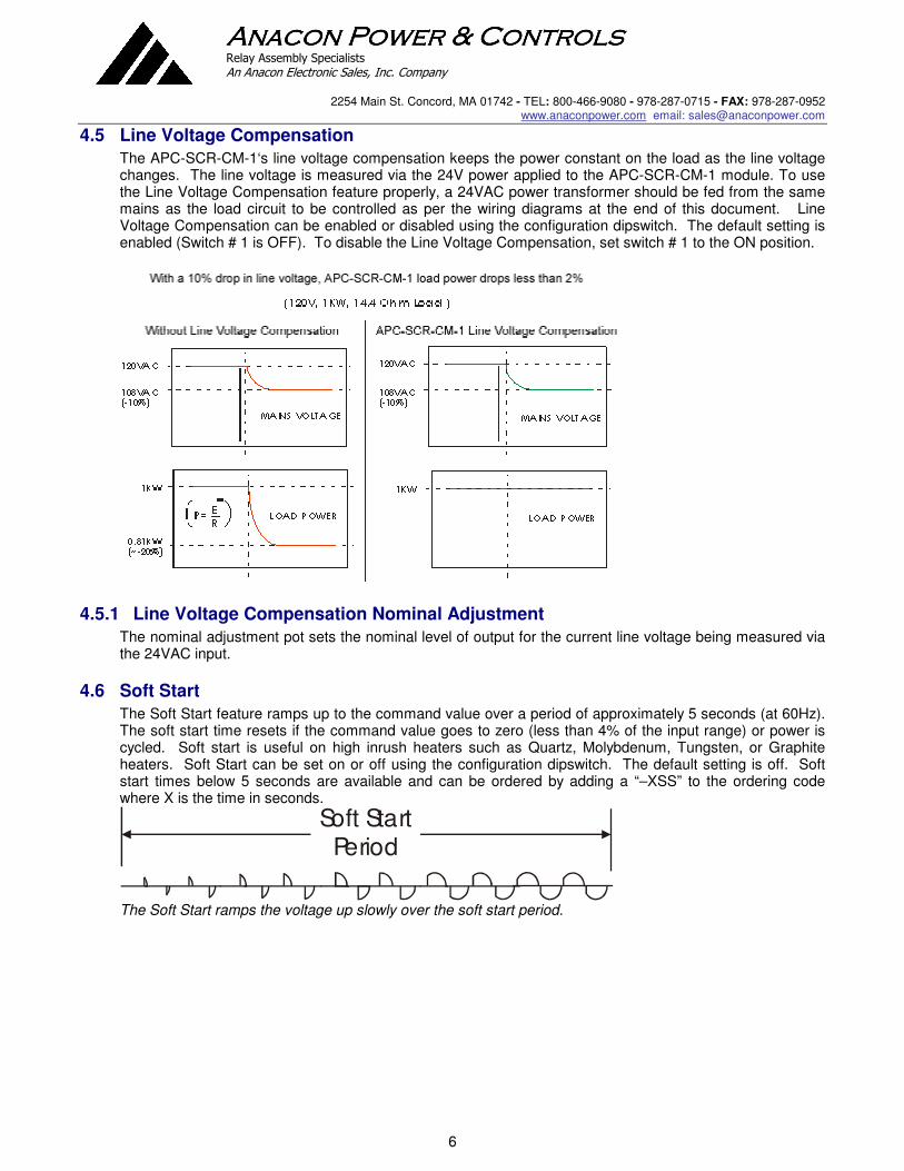
4.5 Line Voltage Compensation
The APC-SCR-CM-1‘s line voltage compensation keeps the power constant on the load as the line voltage changes. The line voltage is measured via the 24V power applied to the APC-SCR-CM-1 module. To use the Line Voltage Compensation feature properly, a 24VAC power transformer should be fed from the same mains as the load circuit to be controlled as per the wiring diagrams at the end of this document. Line Voltage Compensation can be enabled or disabled using the configuration dipswitch. The default setting is enabled (Switch # 1 is OFF). To disable the Line Voltage Compensation, set switch # 1 to the ON position.
4.5.1 Line Voltage Compensation Nominal Adjustment
The nominal adjustment pot sets the nominal level of output for the current line voltage being measured via the 24VAC input.
4.6 Soft Start
The Soft Start feature ramps up to the command value over a period of approximately 5 seconds (at 60Hz). The soft start time resets if the command value goes to zero (less than 4% of the input range) or power is cycled. Soft start is useful on high inrush heaters such as Quartz, Molybdenum, Tungsten, or Graphite heaters. Soft Start can be set on or off using the configuration dipswitch. The default setting is off. Soft start times below 5 seconds are available and can be ordered by adding a “–XSS” to the ordering code where X is the time in seconds.
Soft Start Period
The Soft Start ramps the voltage up slowly over the soft start period.

AnaconAnaconAnaconAnacon Power & ControlsPower & ControlsPower & ControlsPower & Controls Relay Assembly Specialists
An Anacon Electronic Sales, Inc. Company
2254 Main St. Concord, MA 01742 - TEL: 800-466-9080 - 978-287-0715 - FAX: 978-287-0952 www.anaconpower.com email: [email protected]
7
Curre
nt
Time
High Inrush Load
Curre
nt
Time
Soft Start used to limit the inrush
4.7 Voltage Limit
The Voltage Limit feature is used in conjunction with the Line Voltage Compensation feature to limit the actual voltage delivered to the load. The Voltage Limit is adjustable via a potentiometer located just below the input terminal block. For this feature to work properly Line Voltage Compensation must be turned on and the power transformer for the APC-SCR-CM-1 must be connected to the same mains as the load power is connected to. This feature can be used without Line Voltage Compensation and will simply clip the command signal to a set level.
4.7.1 Voltage Limit Adjustment Procedure
The Voltage Limit is adjustable from 5% to 100% of the max load voltage. Setting the Voltage Limit potentiometer half way corresponds to a power limit of approximately 55% or a voltage limit of 70% of the max load voltage. The best way to set the voltage limit is using a voltmeter connected across the load. With the command input set to approximately 100% (on startup) turn the pot fully CCW. Then just turn the pot CW until the desired output voltage is achieved. For this feature to work as a true voltage limit, it is important that the Line Voltage Compensation be enabled (this is the OFF position of Switch # 1). If the line voltage compensation is set to OFF the voltage limit will act as a percentage of output limit and the absolute voltage limit will change with line voltage.
4.8 Configuration Dipswitch
The configuration dipswitch is used for setting up the command input, line voltage compensation and soft start. Using a pen point gently push the switch up for on and down for off according to the setup outlined in the table below.
Command Input 2 4 5 6
0-5V (Default) OFF OFF OFF OFF
Potentiometer OFF OFF OFF OFF
0-10V OFF ON OFF OFF
4-20mA ON OFF ON OFF
1-5V ON OFF OFF OFF
2-10V ON ON OFF OFF
PWM (isolated input) OFF OFF OFF ON
Feature to Enable 1 3
Line Voltage Comp Enabled (default) OFF OFF
None ON OFF
Soft Start Only Enabled ON ON
Soft Start & Line Voltage Comp Enabled OFF ON

AnaconAnaconAnaconAnacon Power & ControlsPower & ControlsPower & ControlsPower & Controls Relay Assembly Specialists
An Anacon Electronic Sales, Inc. Company
2254 Main St. Concord, MA 01742 - TEL: 800-466-9080 - 978-287-0715 - FAX: 978-287-0952 www.anaconpower.com email: [email protected]
8
4.9 SSR Drive Output (APC-SCR-CM-1P- SSR)
The APC-SCR-CM-1’s SSR output drive is a DC-pulsed current limited 10V/15mA (nominal) drive signal. This is more than enough current for driving most 3-32V standard SSRs, however it is still important to review the data sheet for the SSR you would like to use for compatibility with the APC-SCR-CM-1’s output drive. The control output can tolerate a momentary direct short. The following graph will allow you to verify the SSR’s compatibility with the APC-SCR-CM-1 over wide input voltage variations.
APC-SCR-CM-1’s Output Drive Current vs. SSR Input Voltage Drop
4.10 Output LED
The APC-SCR-CM-1’s RED output LED will turn on when the output is on and increase in intensity as the power output is increased. Because the drive signal varies considerably to give linear power output, the LED should only be used as a rough indication of SSR/SCR Drive and not actual power output.
4.11 Three Phase Operation
Three APC-SCR-CM-1s can be used to control three poles of a three phase load for inside delta, or grounded WYE configurations. The Module should be wired as shown in the wiring diagrams.
4.12 Wiring Multiple Units in Single Phase or Three Phase Applications
If more than one APC-SCR-CM-1 is to be used from a non-isolated or common command signals: 1. A common power supply or transformer can be shared. If the input selected is
0-10V or 0-5V, the inputs should be wired in parallel. 2. If multiple units must be powered from one power transformer and 4-20mA input is selected, one
module should be set for 4-20mA and the remaining modules should be set for 1-5V and wired in parallel.
3. If the command is 4-20mA, and the command inputs are to be wired in series, a separate power transformer or supply for each module is required to isolate the inputs.

AnaconAnaconAnaconAnacon Power & ControlsPower & ControlsPower & ControlsPower & Controls Relay Assembly Specialists
An Anacon Electronic Sales, Inc. Company
2254 Main St. Concord, MA 01742 - TEL: 800-466-9080 - 978-287-0715 - FAX: 978-287-0952 www.anaconpower.com email: [email protected]
9
4.12.1 Connecting Power & Commands In Parallel
When multiple APC-SCR-CM-1 power inputs and commands are wired in parallel, all of the 0V terminals must be connected together follows: Power: Command: 0V-----0V-----0V-----> 0V-----0V-----0V-----> 24V---24V---24V----> IN------IN-----IN------> No crossing of the power input feed or command signal is permitted. If for some reason the power should become crossed, it will cause a direct short in the system. If properly fused, the fuse will blow and the APC-SCR-CM-1 will not be damaged. If the command inputs are wired improperly, damage to the APC-SCR-CM-1 can result.
5. Electrical Specifications
Command Inputs 4-20mA, 0-10V, 0-5V, Pot, PWM
Input Impedance 10K Ω (0-10V), 250Ω (4-20mA), 100KΩ (0-5V) Control Output SSR Drive, DC pulse, nominally 10V at 15mA Response Time <50mS PWM Input Frequency 500Hz-15KHz PWM Input Level 5 VDC (non isolated) or 24VDC (isolated) Output Linearity +/-2%
External Potentiometer Res. 10KΩ-25KΩ Line Voltage Comp. Range +15%/-15% up to 100% output Regulation +/-2% Soft Start Period 5 seconds to reach 100% output Voltage Limit Range 5-100% of max load voltage. Ambient Temperature Range 0 to 50 °C Power Supply 24VAC +10/-10%, <100mA Current Draw. Line Frequency Range 30 to 90Hz Line Voltage Range 100-600VAC (External MOV must be installed across SCRs to limit
peak voltages to ~ 850VDC) SCR Gate Drive Characteristics 16KHz Burst for 1.35mS every half cycle. Initial pulse peak current
of 600mA, maintain pulses, 300mA, 10uS pulse width per pulse, rise time of 100nS.

AnaconAnaconAnaconAnacon Power & ControlsPower & ControlsPower & ControlsPower & Controls Relay Assembly Specialists
An Anacon Electronic Sales, Inc. Company
2254 Main St. Concord, MA 01742 - TEL: 800-466-9080 - 978-287-0715 - FAX: 978-287-0952 www.anaconpower.com email: [email protected]
10
6. Mechanical Dimensions

AnaconAnaconAnaconAnacon Power & ControlsPower & ControlsPower & ControlsPower & Controls Relay Assembly Specialists
An Anacon Electronic Sales, Inc. Company
2254 Main St. Concord, MA 01742 - TEL: 800-466-9080 - 978-287-0715 - FAX: 978-287-0952 www.anaconpower.com email: [email protected]
11
7. WIRING DIAGRAM - SINGLE PHASE (SSR OR SCR)

AnaconAnaconAnaconAnacon Power & ControlsPower & ControlsPower & ControlsPower & Controls Relay Assembly Specialists
An Anacon Electronic Sales, Inc. Company
2254 Main St. Concord, MA 01742 - TEL: 800-466-9080 - 978-287-0715 - FAX: 978-287-0952 www.anaconpower.com email: [email protected]
12
8. WIRING DIAGRAM 3 INSIDE DELTA CONNECTION (SSR)

AnaconAnaconAnaconAnacon Power & ControlsPower & ControlsPower & ControlsPower & Controls Relay Assembly Specialists
An Anacon Electronic Sales, Inc. Company
2254 Main St. Concord, MA 01742 - TEL: 800-466-9080 - 978-287-0715 - FAX: 978-287-0952 www.anaconpower.com email: [email protected]
13
9. WIRING DIAGRAM 3 PHASE 4 WIRE Y CONNECTION (SSR)

AnaconAnaconAnaconAnacon Power & ControlsPower & ControlsPower & ControlsPower & Controls Relay Assembly Specialists
An Anacon Electronic Sales, Inc. Company
2254 Main St. Concord, MA 01742 - TEL: 800-466-9080 - 978-287-0715 - FAX: 978-287-0952 www.anaconpower.com email: [email protected]
14
10. WIRING DIAGRAM 3 PHASE 4 WIRE Y CONNECTION (SCR)

AnaconAnaconAnaconAnacon Power & ControlsPower & ControlsPower & ControlsPower & Controls Relay Assembly Specialists
An Anacon Electronic Sales, Inc. Company
2254 Main St. Concord, MA 01742 - TEL: 800-466-9080 - 978-287-0715 - FAX: 978-287-0952 www.anaconpower.com email: [email protected]
15
11. WIRING DIAGRAM 3 PHASE INSIDE DELTA CONNECTION (SCR)

AnaconAnaconAnaconAnacon Power & ControlsPower & ControlsPower & ControlsPower & Controls Relay Assembly Specialists
An Anacon Electronic Sales, Inc. Company
2254 Main St. Concord, MA 01742 - TEL: 800-466-9080 - 978-287-0715 - FAX: 978-287-0952 www.anaconpower.com email: [email protected]
16
12. Contact Information
Anacon Power & Controls
2254 Main St. Concord, MA 01742-3829 TEL: 800-466-9080 TEL: 978-287-0715 FAX: 978-287-0952 EMAIL: [email protected]