Embed Size (px)
Citation preview
D:\legacy\Haes\Drainage\Excel-n-Word\HAES PHASE3DRN Text.docx Page 1 of 11
PHASE III DRAINAGE STUDY
FOR
PROVIDENCE POINT
El Paso County, Colorado
Wednesday, August 27, 2014
PREPARED FOR
Marc and Cheryl Haes 16450 Farrar Road
Colorado Springs, CO 80908 (719) 232-5605
PREPARED BY
Legacy Engineering, Inc. 1626 Thatch Circle
El Paso County, Colorado 80109 (720) 200-4577
PHASE III DRAINAGE STUDY FOR CVR – Providence Point El Paso County, Colorado - August 27, 2014
D:\legacy\Haes\Drainage\Excel-n-Word\HAES PHASE3DRN Text.docx Page 2 of 11
ENGINEER’S STATEMENT:
The enclosed drainage report (PROVIDENCE POINT Phase III Drainage Study), and exhibits (for the Phase III Drainage Study) were prepared by me, or under my direct supervision, and are correct to the best of my knowledge and belief. Said drainage report has been prepared in accordance with applicable El Paso County criteria and is in conformance with the master plan of drainage for the affected area. I accept responsibility for any liability caused by negligent acts, errors or omissions on my part in preparing this report. 08-27-14 Legacy Engineering, Inc. James J. Mill, P.E. (Colorado PE #29256) OWNER/DEVELOPER’S STATEMENT As Owner/Developer of land(s) identified within this report; I agree to proceed, implement and comply with all recommendations and requirements outlined herein. _____________ PROVIDENCE POINT Date Marc Haes EL PASO COUNTY APPROVALS: _____________ Engineering Division Date _____________ Development Services Director Date
PHASE III DRAINAGE STUDY FOR CVR – Providence Point El Paso County, Colorado - August 27, 2014
D:\legacy\Haes\Drainage\Excel-n-Word\HAES PHASE3DRN Text.docx Page 3 of 11
TABLE OF CONTENTS Page
I. GENERAL LOCATION AND DESCRIPTION A. Location..................................................................................... 4 B. Description of Property.............................................................. 4 C. Irrigation Facilities..................................................................... 4 D. Land Use.................................................................................... 4
II. DRAINAGE BASINS AND SUB-BASINS A. Historic Drainage Patterns............................................................. 4
B. Major Basin Description............................................................. 4 C. Sub-Basin Description................................................................ 5
III. DRAINAGE DESIGN CRITERIA A. Regulations................................................................................ 6 B. Development Criteria Reference and Constraints...................... 6 C. Hydrological Criteria.................................................................. 6 D. Hydraulic Criteria....................................................................... 6 E. Sediment & Erosion Control....................................................... 6
IV. DRAINAGE FACILITY DESIGN A. General Concept........................................................................ 7
V. STORMWATER MANAGEMENT PLAN......................................... 7
VI. CONCLUSIONS A. Compliance with Standards....................................................... 10 B. Drainage Concept..................................................................... 10 C. Summary.................................................................................. 10
VII. REFERENCES.................................................................................... 11
Figure Description
APPENDIX A - PROJECT INFORMATION 1 Vicinity Map 2 SCS Soils Map and Soil Properties. 2a Firm Map
APPENDIX B - HYDROLOGY 3 IDF Curve Rainfall Values 5 Composite “I” and “C” Calculations 6 Average Flow Velocities 7 Time of Concentration, Rational Method Calculation Sheet, 5&10 Year
APPENDIX C - HYDRAULICS 8 Culvert Calculations
Drainage Plan
PHASE III DRAINAGE STUDY FOR CVR – Providence Point El Paso County, Colorado - August 27, 2014
D:\legacy\Haes\Drainage\Excel-n-Word\HAES PHASE3DRN Text.docx Page 4 of 11
I. GENERAL LOCATION AND DESCRIPTION
This Phase III Drainage Study for PROVIDENCE POINT has been prepared to address onsite and
offsite drainage concepts in accordance with requirements of El Paso County, Colorado. The
Appendix to this report includes minimum criteria, design computations and reference information
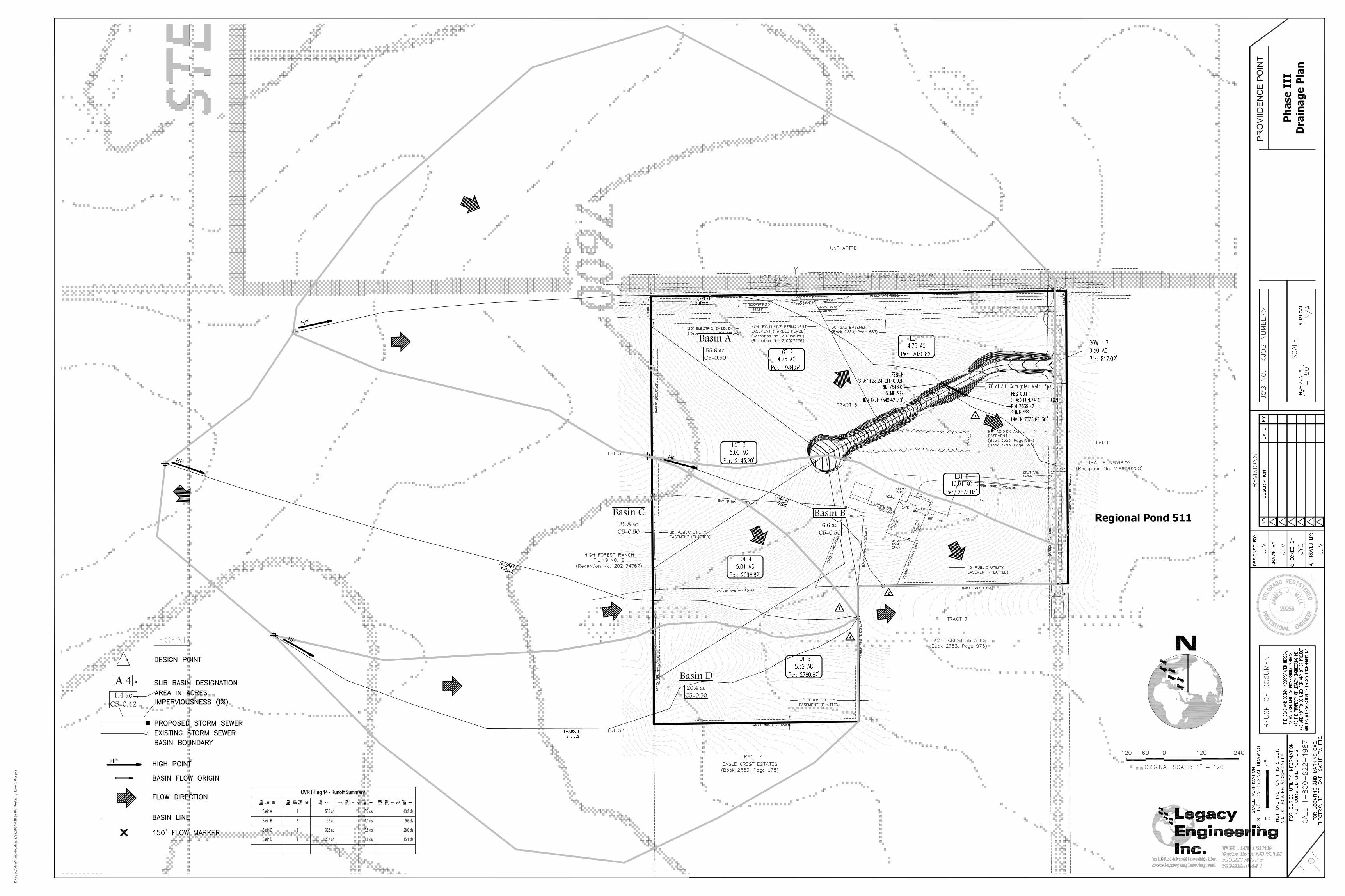
to be used in subsequent phases of analysis and design. The attached Phase III Drainage Plan
summarizes the drainage concepts and conclusions of this study.
A. LOCATION
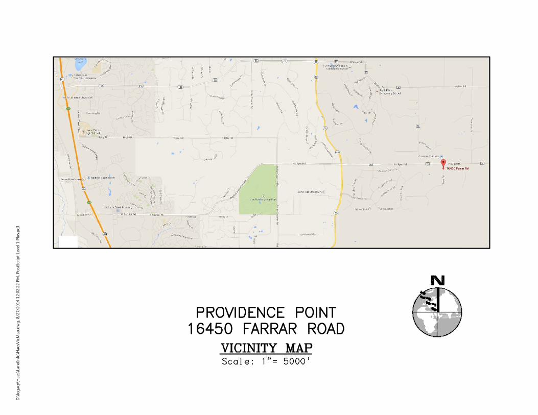
PROVIDENCE POINT, containing a total of 35.34 acres, located in El Paso County as depicted
on Figure 1 in the Appendix. The site is located in the northeast quarter of Section 25, Township
11 South, Range 66 West of the 6th P.M., El Paso County. The site is bounded by High Forest
Ranch Filing 2 on the west, Hodgen Road ROW on the north, Thal Sudvision on the east, and
Tract 7 of Eagle Crest Estates on the south.
B. DESCRIPTION OF PROPERTY
The site is to consist of 35.34 acres to be platted for 6 single family home sites. Existing vegetation
covers the site, which is not irrigated, consisting mainly of native grasses on rolling topography
ranging from 0% to 15%. The site drains to the east-southeast within existing arroyos and swales.
C. IRRIGATION FACILITIES
There are no active irrigation facilities on the site.
D. LAND USE
The development will NOT BE overlot graded for residential development. Providence Point is
zoned for 5 acre min parcels.
II. DRAINAGE BASINS AND SUB-BASINS
A. HISTORIC PATTERNS
Historically, this site has drained to the east-southeast in exiting arroyos and swales. This pattern
will not change with this subdivision and the addition of 5 additional home sites to this 35 acres
will not increase or change the historic storm flows in a measurable way.
B. MAJOR BASIN DESCRIPTION
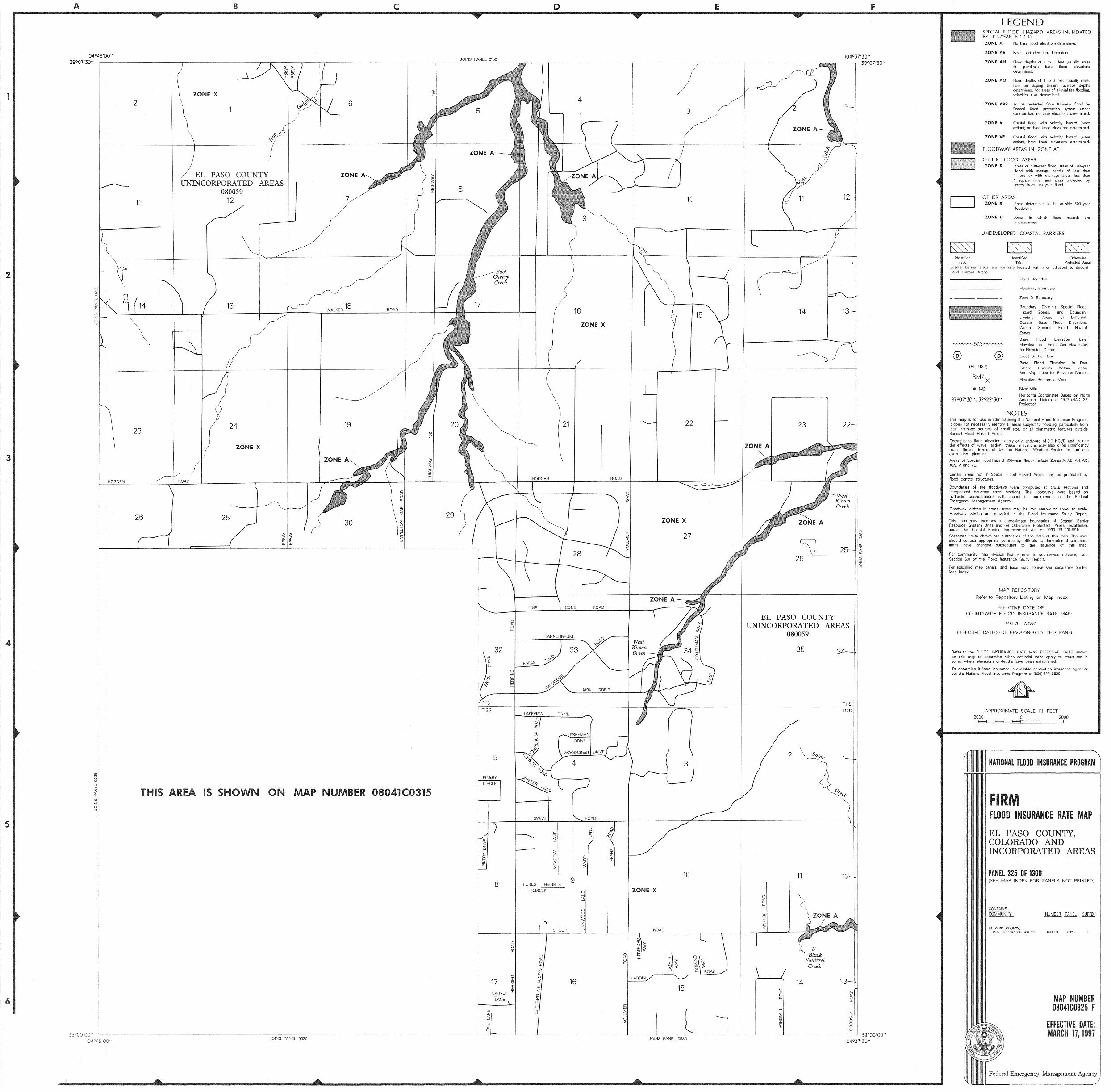
The drainage area which encompasses PROVIDENCE POINT drains entirely to an unnamed
tributary arroyo of E Cherry Creek; the confluence of which is approx. 2 miles to the northeast at
Franktown-Parker FPE-3 Reservoir. According to the FIRM dated March 17, 1997, Map Number
08041CO325 F (reference 3; Figure 2a), there are no mapped A or AE flood zones on this property.
PHASE III DRAINAGE STUDY FOR CVR – Providence Point El Paso County, Colorado - August 27, 2014
D:\legacy\Haes\Drainage\Excel-n-Word\HAES PHASE3DRN Text.docx Page 5 of 11
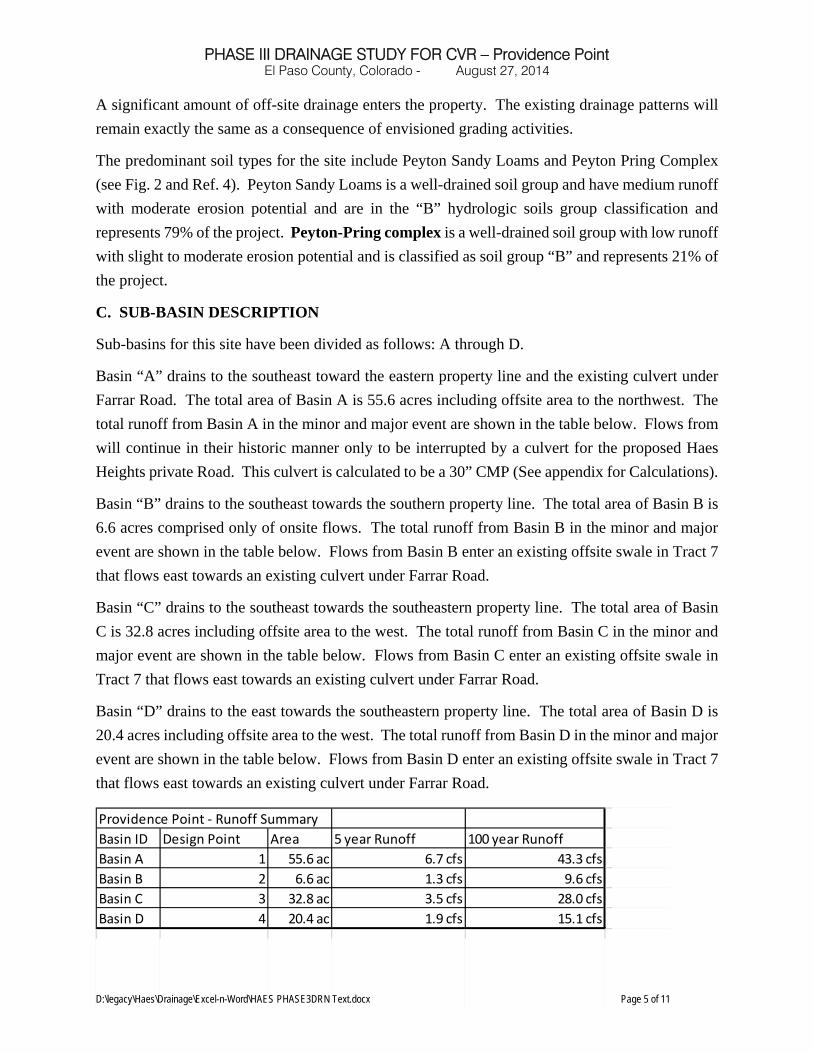
A significant amount of off-site drainage enters the property. The existing drainage patterns will
remain exactly the same as a consequence of envisioned grading activities.
The predominant soil types for the site include Peyton Sandy Loams and Peyton Pring Complex
(see Fig. 2 and Ref. 4). Peyton Sandy Loams is a well-drained soil group and have medium runoff
with moderate erosion potential and are in the “B” hydrologic soils group classification and
represents 79% of the project. Peyton-Pring complex is a well-drained soil group with low runoff
with slight to moderate erosion potential and is classified as soil group “B” and represents 21% of
the project.
C. SUB-BASIN DESCRIPTION
Sub-basins for this site have been divided as follows: A through D.
Basin “A” drains to the southeast toward the eastern property line and the existing culvert under
Farrar Road. The total area of Basin A is 55.6 acres including offsite area to the northwest. The
total runoff from Basin A in the minor and major event are shown in the table below. Flows from
will continue in their historic manner only to be interrupted by a culvert for the proposed Haes
Heights private Road. This culvert is calculated to be a 30” CMP (See appendix for Calculations).
Basin “B” drains to the southeast towards the southern property line. The total area of Basin B is
6.6 acres comprised only of onsite flows. The total runoff from Basin B in the minor and major
event are shown in the table below. Flows from Basin B enter an existing offsite swale in Tract 7
that flows east towards an existing culvert under Farrar Road.
Basin “C” drains to the southeast towards the southeastern property line. The total area of Basin
C is 32.8 acres including offsite area to the west. The total runoff from Basin C in the minor and
major event are shown in the table below. Flows from Basin C enter an existing offsite swale in
Tract 7 that flows east towards an existing culvert under Farrar Road.
Basin “D” drains to the east towards the southeastern property line. The total area of Basin D is
20.4 acres including offsite area to the west. The total runoff from Basin D in the minor and major
event are shown in the table below. Flows from Basin D enter an existing offsite swale in Tract 7
that flows east towards an existing culvert under Farrar Road.
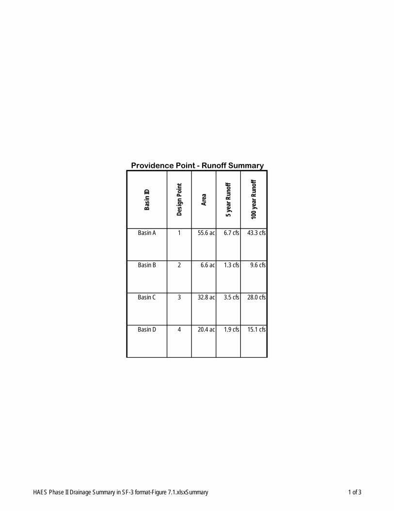
Providence Point ‐ Runoff Summary
Basin ID Design Point Area 5 year Runoff 100 year Runoff
Basin A 1 55.6 ac 6.7 cfs 43.3 cfs
Basin B 2 6.6 ac 1.3 cfs 9.6 cfs
Basin C 3 32.8 ac 3.5 cfs 28.0 cfs
Basin D 4 20.4 ac 1.9 cfs 15.1 cfs
PHASE III DRAINAGE STUDY FOR CVR – Providence Point El Paso County, Colorado - August 27, 2014
D:\legacy\Haes\Drainage\Excel-n-Word\HAES PHASE3DRN Text.docx Page 6 of 11
III. DRAINAGE DESIGN CRITERIA
A. REGULATIONS
Storm drainage analysis and design criteria are to be taken from the "City of Colorado Springs/El
Paso County Drainage Criteria Manual (1994 Revisions), Reference 1
B. DEVELOPMENT CRITERIA REFERENCE AND CONSTRAINTS
Development criteria shall be in accordance with El Paso County Public Works Department.
C. HYDROLOGICAL CRITERIA
The Rational Method was utilized to analyze and quantify runoff from the developed basins.
Design points were used to determine total flows at key points of interest. The 5-year storm event
was used for the initial storm analysis within residential areas and the 100-year storm frequency
was analyzed for the major storm.
D. HYDRAULIC CRITERIA
Sizing calculations for Haes Heights Culvert were completed using Hydraflow Express Storm
Sewers Extension for Autodesk® AutoCAD® Civil 3D® by Autodesk, Inc. (See Appendix C).
E. SEDIMENT AND EROSION CONTROL
Site soils are typical of the area and will require careful erosion and sediment control methods.
Construction sedimentation will be controlled, to meet El Paso County Performance Standards.
Specifics of this erosion control plan will be demonstrated in the Grading, Erosion, and
Sedimentation Control Plan that will be included in the construction plan set at time of Final Plat.
No unsuitability of the site soils with regard to construction of this development have been
identified thus far.
PHASE III DRAINAGE STUDY FOR CVR – Providence Point El Paso County, Colorado - August 27, 2014
D:\legacy\Haes\Drainage\Excel-n-Word\HAES PHASE3DRN Text.docx Page 7 of 11
IV. DRAINAGE FACILITY DESIGN
A. GENERAL CONCEPT
The general concept is to convey storm water via natural drainage-ways, culverts, to the unnamed
E Cherry Creek tributary at the eastern boundary of PROVIDENCE POINT. Basins consist of
rural lots, 1 private roadway, natural drainage-ways and open space.
Figure 1 is a vicinity map showing approximately where the PROVIDENCE POINT development
is located. Figure 2 presents the soil classifications found within the site. Figure 2a presents a
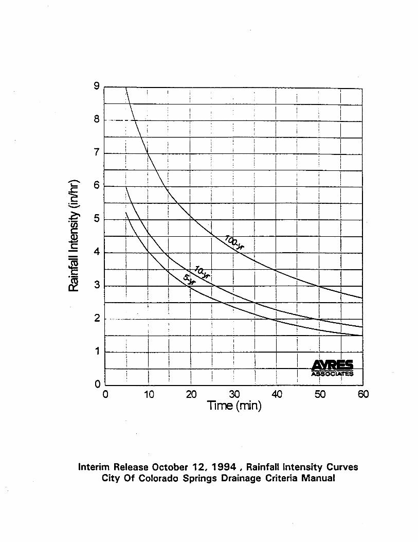
“firmette” for Map Number 08041CO325 F. Figure 3 is the IDF Curve for El Paso County. Figure
4 contains the time-intensity-frequency curves for El Paso County. Figure 5 shows calculations
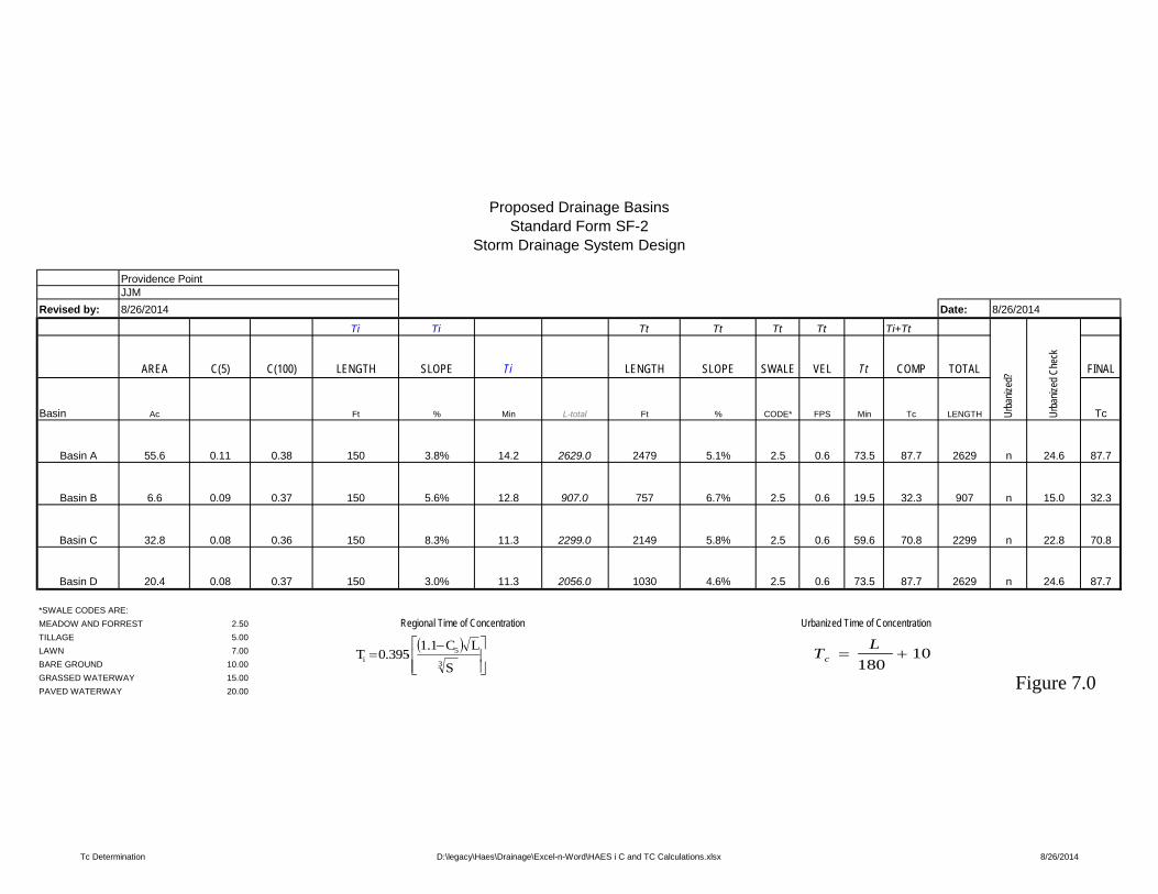
for a composite “I” value. Figure 6 presents average flow velocities for use with the rational
method. Figure 7 contains time of concentration calculations and peak storm flows using rational
method calculation sheets for the 5 and 100 year storm events, respectively for each basin. Figures
in Appendix C contain culvert design calculations. An overall drainage map is provided at the end
of this report.
Historic Basins: All existing basins and proposed basins shown in this development are exactly
the same.
V. STORMWATER MANAGEMENT PLAN
A. SITE DESCRIPTION
a) The proposed construction activity is development of single family homes with all
relevant infrastructure including, but not limited to, streets, utilities, and drainage
improvements.
b) The anticipated sequence of construction is as follows:
1. Installation of perimeter erosion control measures
2. Site clearing
3. Pad grading
4. Installation of temporary onsite erosion control measures and temporary
traps
5. Utility construction
6. Drainage improvements construction including sediment traps at inlets and
erosion protection at outfall locations.
7. Road grading
PHASE III DRAINAGE STUDY FOR CVR – Providence Point El Paso County, Colorado - August 27, 2014
D:\legacy\Haes\Drainage\Excel-n-Word\HAES PHASE3DRN Text.docx Page 8 of 11
8. Street preparation
9. Street paving
10. Seeding and mulching of all disturbed areas
11. Removal of erosion control appurtenances after site is stabilized
c) The total area of the site is approximately 35 acres. The area of the site expected
to undergo grading activities is approximately 2 acres.
d) Soils data are identified in the Appendix.
e) Vegetation on the site consists mainly of native grasses covering 100% of the site.
f) Potential pollution sources include equipment refueling and maintenance, grading
operations, and concrete wash water.
g) No significant non-storm waters of runoff are anticipated.
h) The receiving water course is an unnamed tributary of East Cherry Creek, then East
Cherry Creek, then South Platte,
B. APPROPRIATE DRAWINGS
The appropriate maps, taken from the "Construction Plans include: Overlot Grading Plan; Erosion
Control Plan; Overlot Grading and Erosion Control Details. The drainage map is enclosed and
also provides additional relevant information.
C. BEST MANAGEMENT PRACTICES (BMP) FOR STORMWATER POLLUTION
PREVENTION
a) Erosion and Sediment Control
1. Structural Practices: Overlot grading operations present the greatest
opportunity for pollution of State waters. Disturbed areas shall be contained
by a perimeter silt fence at downslope conditions which shall remain at the
downstream perimeter of all overland flow until non-structural ways and
means are established. Upon completion of the overlot grading, surface
runoff velocities shall be attenuated by slope reduction and erosion bales as
check dams. The grading improvements generally direct runoff to a central
point of site release thereby permitting point source methods of pollution
abatement management practices, more particularly the detention pond.
Surface areas remain denuded during utility construction, but the structural
PHASE III DRAINAGE STUDY FOR CVR – Providence Point El Paso County, Colorado - August 27, 2014
D:\legacy\Haes\Drainage\Excel-n-Word\HAES PHASE3DRN Text.docx Page 9 of 11
elements remain in place. Maintenance procedures shall be recorded by the
developer's construction manager in a log book.
2. Non-structural Practices: Upon completion of the street hardscape, all
exposed portions of the site not slated for house construction shall be seeded
and mulched. Silt and sediment deposits shall be removed and spread
evenly in open areas and shall be seeded and mulched as necessary. Upon
establishment of surface vegetation, structural erosion control measures
shall then be removed whereby non-structural methods shall be practiced.
b) Materials Handling and Spill Prevention
Potential pollutant materials brought onsite would be fuels for earthmoving and trenching
equipment. Berms shall be provided at the fueling site as a containment measure. There will be
no permanent bulk fuel storage on this site. The Black Forest Fire Protection District is presumed
to be equipped for spill cleanup and any contaminated materials shall be properly disposed at the
contractor expense. Other potential pollutant materials include concrete wash water. This shall
be done in areas designated by the developer's construction manager and protected from runoff
and, after hydration, be buried in designated non-construction zones.
Building materials are expensive and shall be protected by storage outside of runoff areas. This
shall be performed by the owner of the materials so as to protect the inherent value. No additional
materials handling measures will be taken.
Waste building materials shall be collected by a reputable waste management company and
transported to a legal waste disposal facility. Site inspections shall be performed weekly to assure
onsite collection. No dedicated concrete or asphalt batch plants are proposed on the site.
D. FINAL STABILIZATION AND LONG TERM STORMWATER MANAGEMENT
After infrastructure construction is complete, runoff will be directed by a street network to a storm
sewer system and detention pond and then released. After completion of this project, the open
space areas are landscaped and maintained by the home owners association. The storm water is
then classified as urban runoff.
PHASE III DRAINAGE STUDY FOR CVR – Providence Point El Paso County, Colorado - August 27, 2014
D:\legacy\Haes\Drainage\Excel-n-Word\HAES PHASE3DRN Text.docx Page 10 of 11
E. OTHER CONTROLS
Offsite soil tracking is limited by restriction of construction traffic to one access point and by
periodic maintenance. Implementation of the controls shall be by the erosion control plan which
is a part of the contract documents.
F. INSPECTION AND MAINTENANCE
Maintenance procedures are outlined in the notes contained on the overlot grading and erosion
control plans and respective details. A log record noting all inspections and mitigation efforts shall
be kept with the construction manager.
VI. CONCLUSIONS
A. COMPLIANCE WITH STANDARDS
This Phase III Drainage Study for PROVIDENCE POINT was prepared in compliance with the El
Paso County Public Works Regulations. In addition, no amendment to the Flood Hazard Area
Delineation for this area is required for this development. There are no impacts to any threatened
or endangered species that we are aware of. All Federal and State environmental permitting
requirements, should they be necessary, will be complied with – this includes a State of Colorado
Storm Water Discharge Permit.
B. DRAINAGE CONCEPT
The drainage designs and facilities presented in this report adequately convey developed runoff
through the site and into existing drainage ways without increasing the existing discharge.
C. SUMMARY
The report provides sufficient information to accommodate the planning process. Information
herein supports the viability of this proposed project.
PHASE III DRAINAGE STUDY FOR CVR – Providence Point El Paso County, Colorado - August 27, 2014
D:\legacy\Haes\Drainage\Excel-n-Word\HAES PHASE3DRN Text.docx Page 11 of 11
VII. References
1) City of Colorado Springs/El Paso County Drainage Criteria Manual (1994 Revisions)
2) Flood Insurance Rate Map, Douglas County, Colorado, Map Number 08041CO325
March 17th, 1997, prepared by FEMA.
3) Soil Survey of El Paso County Area, Colorado, U.S. Department of Agriculture, Soil
Conservation Service, issued November, 1974.
4) Software used - AutoDesk Civil 3D 2015; Microsoft Excel 2013; Microsoft Word 2013;
UDFCD Excel Spreadsheets;
D:\legacy\CVR\CVR14\Drainage\CVR14 DRAINAGE APPENDIX Labels.docx A
APPENDIX A - PROJECT INFORMATION
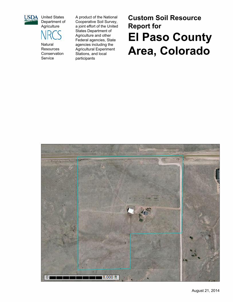
United StatesDepartment ofAgriculture
A product of the NationalCooperative Soil Survey,a joint effort of the UnitedStates Department ofAgriculture and otherFederal agencies, Stateagencies including theAgricultural ExperimentStations, and localparticipants
Custom Soil ResourceReport for
El Paso CountyArea, Colorado
NaturalResourcesConservationService
August 21, 2014
PrefaceSoil surveys contain information that affects land use planning in survey areas. Theyhighlight soil limitations that affect various land uses and provide information aboutthe properties of the soils in the survey areas. Soil surveys are designed for manydifferent users, including farmers, ranchers, foresters, agronomists, urban planners,community officials, engineers, developers, builders, and home buyers. Also,conservationists, teachers, students, and specialists in recreation, waste disposal,and pollution control can use the surveys to help them understand, protect, or enhancethe environment.
Various land use regulations of Federal, State, and local governments may imposespecial restrictions on land use or land treatment. Soil surveys identify soil propertiesthat are used in making various land use or land treatment decisions. The informationis intended to help the land users identify and reduce the effects of soil limitations onvarious land uses. The landowner or user is responsible for identifying and complyingwith existing laws and regulations.
Although soil survey information can be used for general farm, local, and wider areaplanning, onsite investigation is needed to supplement this information in some cases.Examples include soil quality assessments (http://www.nrcs.usda.gov/wps/portal/nrcs/main/soils/health/) and certain conservation and engineering applications. Formore detailed information, contact your local USDA Service Center (http://offices.sc.egov.usda.gov/locator/app?agency=nrcs) or your NRCS State SoilScientist (http://www.nrcs.usda.gov/wps/portal/nrcs/detail/soils/contactus/?cid=nrcs142p2_053951).
Great differences in soil properties can occur within short distances. Some soils areseasonally wet or subject to flooding. Some are too unstable to be used as afoundation for buildings or roads. Clayey or wet soils are poorly suited to use as septictank absorption fields. A high water table makes a soil poorly suited to basements orunderground installations.
The National Cooperative Soil Survey is a joint effort of the United States Departmentof Agriculture and other Federal agencies, State agencies including the AgriculturalExperiment Stations, and local agencies. The Natural Resources ConservationService (NRCS) has leadership for the Federal part of the National Cooperative SoilSurvey.
Information about soils is updated periodically. Updated information is availablethrough the NRCS Web Soil Survey, the site for official soil survey information.
The U.S. Department of Agriculture (USDA) prohibits discrimination in all its programsand activities on the basis of race, color, national origin, age, disability, and whereapplicable, sex, marital status, familial status, parental status, religion, sexualorientation, genetic information, political beliefs, reprisal, or because all or a part of anindividual's income is derived from any public assistance program. (Not all prohibitedbases apply to all programs.) Persons with disabilities who require alternative means
2

for communication of program information (Braille, large print, audiotape, etc.) shouldcontact USDA's TARGET Center at (202) 720-2600 (voice and TDD). To file acomplaint of discrimination, write to USDA, Director, Office of Civil Rights, 1400Independence Avenue, S.W., Washington, D.C. 20250-9410 or call (800) 795-3272(voice) or (202) 720-6382 (TDD). USDA is an equal opportunity provider andemployer.
3
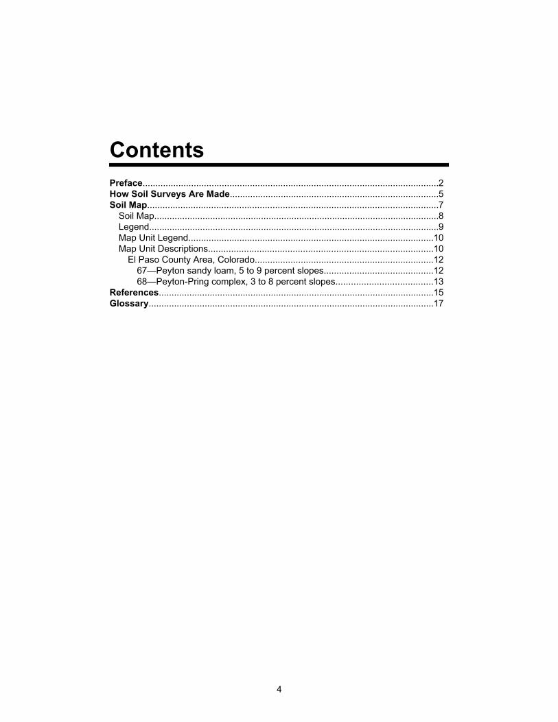
ContentsPreface....................................................................................................................2How Soil Surveys Are Made..................................................................................5Soil Map..................................................................................................................7
Soil Map................................................................................................................8Legend..................................................................................................................9Map Unit Legend................................................................................................10Map Unit Descriptions........................................................................................10
El Paso County Area, Colorado......................................................................1267—Peyton sandy loam, 5 to 9 percent slopes...........................................1268—Peyton-Pring complex, 3 to 8 percent slopes......................................13
References............................................................................................................15Glossary................................................................................................................17
4
How Soil Surveys Are MadeSoil surveys are made to provide information about the soils and miscellaneous areasin a specific area. They include a description of the soils and miscellaneous areas andtheir location on the landscape and tables that show soil properties and limitationsaffecting various uses. Soil scientists observed the steepness, length, and shape ofthe slopes; the general pattern of drainage; the kinds of crops and native plants; andthe kinds of bedrock. They observed and described many soil profiles. A soil profile isthe sequence of natural layers, or horizons, in a soil. The profile extends from thesurface down into the unconsolidated material in which the soil formed or from thesurface down to bedrock. The unconsolidated material is devoid of roots and otherliving organisms and has not been changed by other biological activity.
Currently, soils are mapped according to the boundaries of major land resource areas(MLRAs). MLRAs are geographically associated land resource units that sharecommon characteristics related to physiography, geology, climate, water resources,soils, biological resources, and land uses (USDA, 2006). Soil survey areas typicallyconsist of parts of one or more MLRA.
The soils and miscellaneous areas in a survey area occur in an orderly pattern that isrelated to the geology, landforms, relief, climate, and natural vegetation of the area.Each kind of soil and miscellaneous area is associated with a particular kind oflandform or with a segment of the landform. By observing the soils and miscellaneousareas in the survey area and relating their position to specific segments of thelandform, a soil scientist develops a concept, or model, of how they were formed. Thus,during mapping, this model enables the soil scientist to predict with a considerabledegree of accuracy the kind of soil or miscellaneous area at a specific location on thelandscape.
Commonly, individual soils on the landscape merge into one another as theircharacteristics gradually change. To construct an accurate soil map, however, soilscientists must determine the boundaries between the soils. They can observe onlya limited number of soil profiles. Nevertheless, these observations, supplemented byan understanding of the soil-vegetation-landscape relationship, are sufficient to verifypredictions of the kinds of soil in an area and to determine the boundaries.
Soil scientists recorded the characteristics of the soil profiles that they studied. Theynoted soil color, texture, size and shape of soil aggregates, kind and amount of rockfragments, distribution of plant roots, reaction, and other features that enable them toidentify soils. After describing the soils in the survey area and determining theirproperties, the soil scientists assigned the soils to taxonomic classes (units).Taxonomic classes are concepts. Each taxonomic class has a set of soilcharacteristics with precisely defined limits. The classes are used as a basis forcomparison to classify soils systematically. Soil taxonomy, the system of taxonomicclassification used in the United States, is based mainly on the kind and character ofsoil properties and the arrangement of horizons within the profile. After the soilscientists classified and named the soils in the survey area, they compared the
5
individual soils with similar soils in the same taxonomic class in other areas so thatthey could confirm data and assemble additional data based on experience andresearch.
The objective of soil mapping is not to delineate pure map unit components; theobjective is to separate the landscape into landforms or landform segments that havesimilar use and management requirements. Each map unit is defined by a uniquecombination of soil components and/or miscellaneous areas in predictableproportions. Some components may be highly contrasting to the other components ofthe map unit. The presence of minor components in a map unit in no way diminishesthe usefulness or accuracy of the data. The delineation of such landforms andlandform segments on the map provides sufficient information for the development ofresource plans. If intensive use of small areas is planned, onsite investigation isneeded to define and locate the soils and miscellaneous areas.
Soil scientists make many field observations in the process of producing a soil map.The frequency of observation is dependent upon several factors, including scale ofmapping, intensity of mapping, design of map units, complexity of the landscape, andexperience of the soil scientist. Observations are made to test and refine the soil-landscape model and predictions and to verify the classification of the soils at specificlocations. Once the soil-landscape model is refined, a significantly smaller number ofmeasurements of individual soil properties are made and recorded. Thesemeasurements may include field measurements, such as those for color, depth tobedrock, and texture, and laboratory measurements, such as those for content ofsand, silt, clay, salt, and other components. Properties of each soil typically vary fromone point to another across the landscape.
Observations for map unit components are aggregated to develop ranges ofcharacteristics for the components. The aggregated values are presented. Directmeasurements do not exist for every property presented for every map unitcomponent. Values for some properties are estimated from combinations of otherproperties.
While a soil survey is in progress, samples of some of the soils in the area generallyare collected for laboratory analyses and for engineering tests. Soil scientists interpretthe data from these analyses and tests as well as the field-observed characteristicsand the soil properties to determine the expected behavior of the soils under differentuses. Interpretations for all of the soils are field tested through observation of the soilsin different uses and under different levels of management. Some interpretations aremodified to fit local conditions, and some new interpretations are developed to meetlocal needs. Data are assembled from other sources, such as research information,production records, and field experience of specialists. For example, data on cropyields under defined levels of management are assembled from farm records and fromfield or plot experiments on the same kinds of soil.
Predictions about soil behavior are based not only on soil properties but also on suchvariables as climate and biological activity. Soil conditions are predictable over longperiods of time, but they are not predictable from year to year. For example, soilscientists can predict with a fairly high degree of accuracy that a given soil will havea high water table within certain depths in most years, but they cannot predict that ahigh water table will always be at a specific level in the soil on a specific date.
After soil scientists located and identified the significant natural bodies of soil in thesurvey area, they drew the boundaries of these bodies on aerial photographs andidentified each as a specific map unit. Aerial photographs show trees, buildings, fields,roads, and rivers, all of which help in locating boundaries accurately.
Custom Soil Resource Report
6
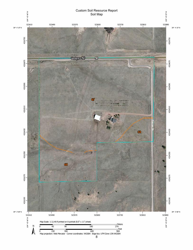
Soil MapThe soil map section includes the soil map for the defined area of interest, a list of soilmap units on the map and extent of each map unit, and cartographic symbolsdisplayed on the map. Also presented are various metadata about data used toproduce the map, and a description of each soil map unit.
7
8
Custom Soil Resource ReportSoil Map
4324
190
4324
270
4324
350
4324
430
4324
510
4324
590
4324
670
4324
750
4324
190
4324
270
4324
350
4324
430
4324
510
4324
590
4324
670
4324
750
523410 523490 523570 523650 523730 523810 523890
523410 523490 523570 523650 523730 523810 523890
39° 4' 19'' N10
4° 4
3' 4
6'' W
39° 4' 19'' N
104°
43'
25'
' W
39° 3' 58'' N
104°
43'
46'
' W
39° 3' 58'' N
104°
43'
25'
' W
N
Map projection: Web Mercator Corner coordinates: WGS84 Edge tics: UTM Zone 13N WGS840 150 300 600 900
Feet0 45 90 180 270
MetersMap Scale: 1:3,140 if printed on A portrait (8.5" x 11") sheet.
MAP LEGEND MAP INFORMATION
Area of Interest (AOI)Area of Interest (AOI)
SoilsSoil Map Unit Polygons
Soil Map Unit Lines
Soil Map Unit Points
Special Point FeaturesBlowout
Borrow Pit
Clay Spot
Closed Depression
Gravel Pit
Gravelly Spot
Landfill
Lava Flow
Marsh or swamp
Mine or Quarry
Miscellaneous Water
Perennial Water
Rock Outcrop
Saline Spot
Sandy Spot
Severely Eroded Spot
Sinkhole
Slide or Slip
Sodic Spot
Spoil Area
Stony Spot
Very Stony Spot
Wet Spot
Other
Special Line Features
Water FeaturesStreams and Canals
TransportationRails
Interstate Highways
US Routes
Major Roads
Local Roads
BackgroundAerial Photography
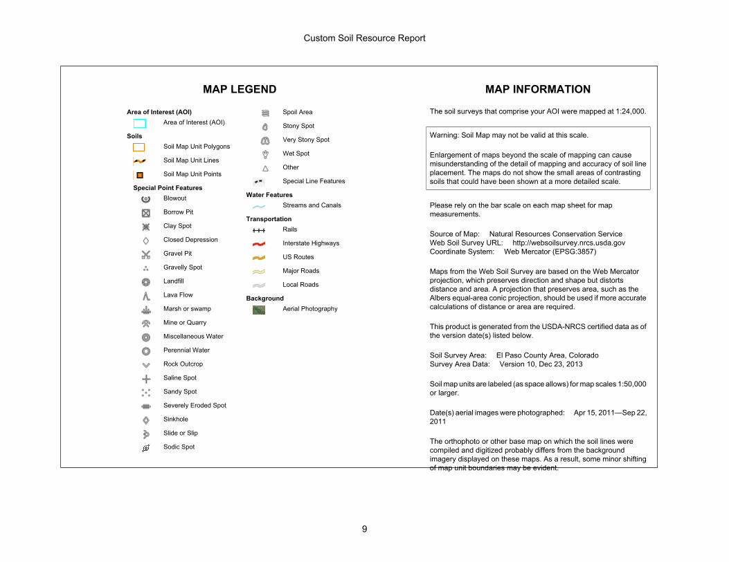
The soil surveys that comprise your AOI were mapped at 1:24,000.
Warning: Soil Map may not be valid at this scale.
Enlargement of maps beyond the scale of mapping can causemisunderstanding of the detail of mapping and accuracy of soil lineplacement. The maps do not show the small areas of contrastingsoils that could have been shown at a more detailed scale.
Please rely on the bar scale on each map sheet for mapmeasurements.
Source of Map: Natural Resources Conservation ServiceWeb Soil Survey URL: http://websoilsurvey.nrcs.usda.govCoordinate System: Web Mercator (EPSG:3857)
Maps from the Web Soil Survey are based on the Web Mercatorprojection, which preserves direction and shape but distortsdistance and area. A projection that preserves area, such as theAlbers equal-area conic projection, should be used if more accuratecalculations of distance or area are required.
This product is generated from the USDA-NRCS certified data as ofthe version date(s) listed below.
Soil Survey Area: El Paso County Area, ColoradoSurvey Area Data: Version 10, Dec 23, 2013
Soil map units are labeled (as space allows) for map scales 1:50,000or larger.
Date(s) aerial images were photographed: Apr 15, 2011—Sep 22,2011
The orthophoto or other base map on which the soil lines werecompiled and digitized probably differs from the backgroundimagery displayed on these maps. As a result, some minor shiftingof map unit boundaries may be evident.
Custom Soil Resource Report
9
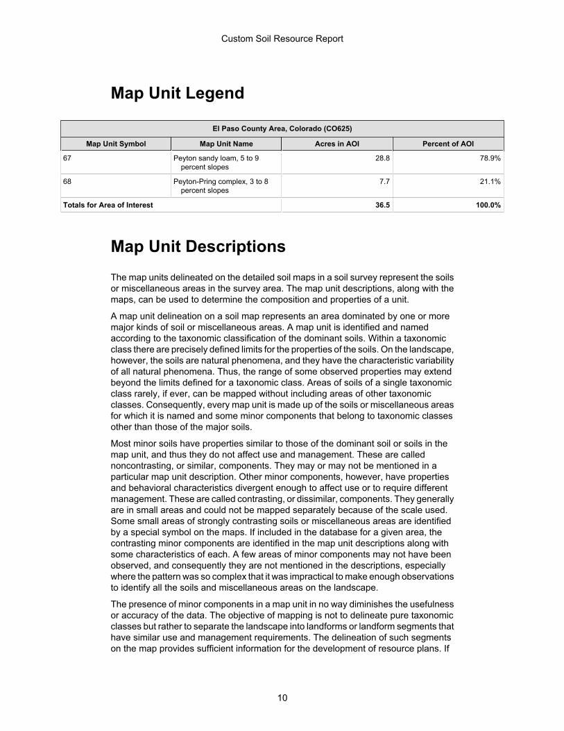
Map Unit Legend
El Paso County Area, Colorado (CO625)
Map Unit Symbol Map Unit Name Acres in AOI Percent of AOI
67 Peyton sandy loam, 5 to 9percent slopes
28.8 78.9%
68 Peyton-Pring complex, 3 to 8percent slopes
7.7 21.1%
Totals for Area of Interest 36.5 100.0%
Map Unit DescriptionsThe map units delineated on the detailed soil maps in a soil survey represent the soilsor miscellaneous areas in the survey area. The map unit descriptions, along with themaps, can be used to determine the composition and properties of a unit.
A map unit delineation on a soil map represents an area dominated by one or moremajor kinds of soil or miscellaneous areas. A map unit is identified and namedaccording to the taxonomic classification of the dominant soils. Within a taxonomicclass there are precisely defined limits for the properties of the soils. On the landscape,however, the soils are natural phenomena, and they have the characteristic variabilityof all natural phenomena. Thus, the range of some observed properties may extendbeyond the limits defined for a taxonomic class. Areas of soils of a single taxonomicclass rarely, if ever, can be mapped without including areas of other taxonomicclasses. Consequently, every map unit is made up of the soils or miscellaneous areasfor which it is named and some minor components that belong to taxonomic classesother than those of the major soils.
Most minor soils have properties similar to those of the dominant soil or soils in themap unit, and thus they do not affect use and management. These are callednoncontrasting, or similar, components. They may or may not be mentioned in aparticular map unit description. Other minor components, however, have propertiesand behavioral characteristics divergent enough to affect use or to require differentmanagement. These are called contrasting, or dissimilar, components. They generallyare in small areas and could not be mapped separately because of the scale used.Some small areas of strongly contrasting soils or miscellaneous areas are identifiedby a special symbol on the maps. If included in the database for a given area, thecontrasting minor components are identified in the map unit descriptions along withsome characteristics of each. A few areas of minor components may not have beenobserved, and consequently they are not mentioned in the descriptions, especiallywhere the pattern was so complex that it was impractical to make enough observationsto identify all the soils and miscellaneous areas on the landscape.
The presence of minor components in a map unit in no way diminishes the usefulnessor accuracy of the data. The objective of mapping is not to delineate pure taxonomicclasses but rather to separate the landscape into landforms or landform segments thathave similar use and management requirements. The delineation of such segmentson the map provides sufficient information for the development of resource plans. If
Custom Soil Resource Report
10
intensive use of small areas is planned, however, onsite investigation is needed todefine and locate the soils and miscellaneous areas.
An identifying symbol precedes the map unit name in the map unit descriptions. Eachdescription includes general facts about the unit and gives important soil propertiesand qualities.
Soils that have profiles that are almost alike make up a soil series. Except fordifferences in texture of the surface layer, all the soils of a series have major horizonsthat are similar in composition, thickness, and arrangement.
Soils of one series can differ in texture of the surface layer, slope, stoniness, salinity,degree of erosion, and other characteristics that affect their use. On the basis of suchdifferences, a soil series is divided into soil phases. Most of the areas shown on thedetailed soil maps are phases of soil series. The name of a soil phase commonlyindicates a feature that affects use or management. For example, Alpha silt loam, 0to 2 percent slopes, is a phase of the Alpha series.
Some map units are made up of two or more major soils or miscellaneous areas.These map units are complexes, associations, or undifferentiated groups.
A complex consists of two or more soils or miscellaneous areas in such an intricatepattern or in such small areas that they cannot be shown separately on the maps. Thepattern and proportion of the soils or miscellaneous areas are somewhat similar in allareas. Alpha-Beta complex, 0 to 6 percent slopes, is an example.
An association is made up of two or more geographically associated soils ormiscellaneous areas that are shown as one unit on the maps. Because of present oranticipated uses of the map units in the survey area, it was not considered practicalor necessary to map the soils or miscellaneous areas separately. The pattern andrelative proportion of the soils or miscellaneous areas are somewhat similar. Alpha-Beta association, 0 to 2 percent slopes, is an example.
An undifferentiated group is made up of two or more soils or miscellaneous areas thatcould be mapped individually but are mapped as one unit because similarinterpretations can be made for use and management. The pattern and proportion ofthe soils or miscellaneous areas in a mapped area are not uniform. An area can bemade up of only one of the major soils or miscellaneous areas, or it can be made upof all of them. Alpha and Beta soils, 0 to 2 percent slopes, is an example.
Some surveys include miscellaneous areas. Such areas have little or no soil materialand support little or no vegetation. Rock outcrop is an example.
Custom Soil Resource Report
11
El Paso County Area, Colorado
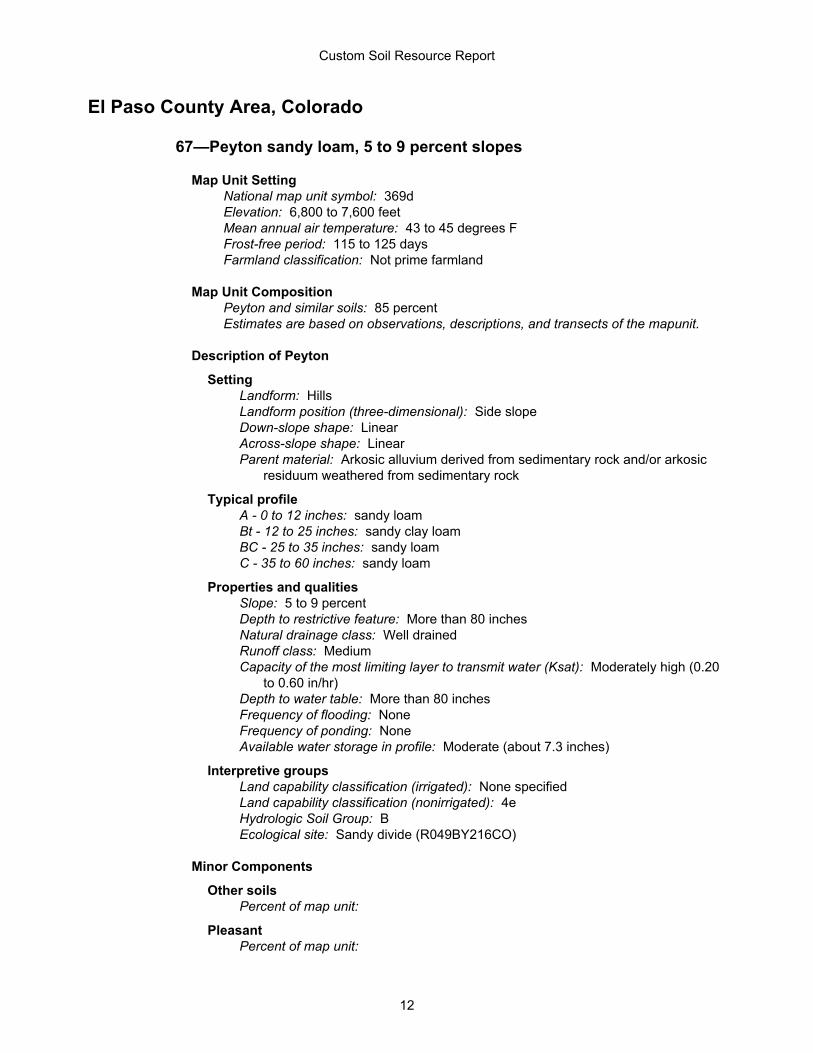
67—Peyton sandy loam, 5 to 9 percent slopes
Map Unit SettingNational map unit symbol: 369dElevation: 6,800 to 7,600 feetMean annual air temperature: 43 to 45 degrees FFrost-free period: 115 to 125 daysFarmland classification: Not prime farmland
Map Unit CompositionPeyton and similar soils: 85 percentEstimates are based on observations, descriptions, and transects of the mapunit.
Description of Peyton
SettingLandform: HillsLandform position (three-dimensional): Side slopeDown-slope shape: LinearAcross-slope shape: LinearParent material: Arkosic alluvium derived from sedimentary rock and/or arkosic
residuum weathered from sedimentary rock
Typical profileA - 0 to 12 inches: sandy loamBt - 12 to 25 inches: sandy clay loamBC - 25 to 35 inches: sandy loamC - 35 to 60 inches: sandy loam
Properties and qualitiesSlope: 5 to 9 percentDepth to restrictive feature: More than 80 inchesNatural drainage class: Well drainedRunoff class: MediumCapacity of the most limiting layer to transmit water (Ksat): Moderately high (0.20
to 0.60 in/hr)Depth to water table: More than 80 inchesFrequency of flooding: NoneFrequency of ponding: NoneAvailable water storage in profile: Moderate (about 7.3 inches)
Interpretive groupsLand capability classification (irrigated): None specifiedLand capability classification (nonirrigated): 4eHydrologic Soil Group: BEcological site: Sandy divide (R049BY216CO)
Minor Components
Other soilsPercent of map unit:
PleasantPercent of map unit:
Custom Soil Resource Report
12
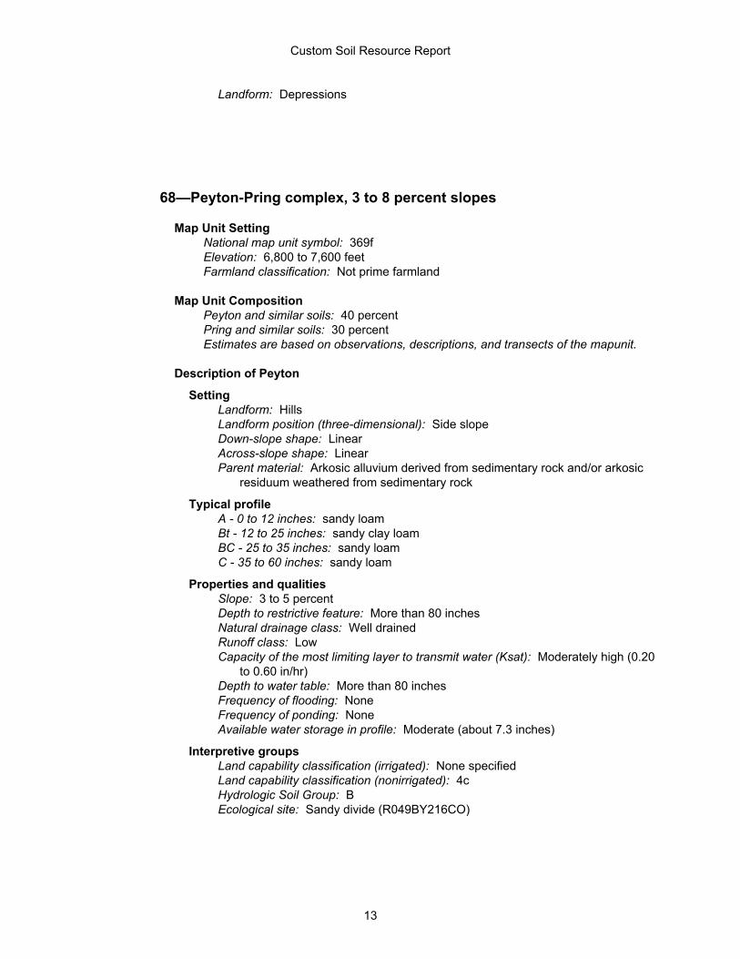
Landform: Depressions
68—Peyton-Pring complex, 3 to 8 percent slopes
Map Unit SettingNational map unit symbol: 369fElevation: 6,800 to 7,600 feetFarmland classification: Not prime farmland
Map Unit CompositionPeyton and similar soils: 40 percentPring and similar soils: 30 percentEstimates are based on observations, descriptions, and transects of the mapunit.
Description of Peyton
SettingLandform: HillsLandform position (three-dimensional): Side slopeDown-slope shape: LinearAcross-slope shape: LinearParent material: Arkosic alluvium derived from sedimentary rock and/or arkosic
residuum weathered from sedimentary rock
Typical profileA - 0 to 12 inches: sandy loamBt - 12 to 25 inches: sandy clay loamBC - 25 to 35 inches: sandy loamC - 35 to 60 inches: sandy loam
Properties and qualitiesSlope: 3 to 5 percentDepth to restrictive feature: More than 80 inchesNatural drainage class: Well drainedRunoff class: LowCapacity of the most limiting layer to transmit water (Ksat): Moderately high (0.20
to 0.60 in/hr)Depth to water table: More than 80 inchesFrequency of flooding: NoneFrequency of ponding: NoneAvailable water storage in profile: Moderate (about 7.3 inches)
Interpretive groupsLand capability classification (irrigated): None specifiedLand capability classification (nonirrigated): 4cHydrologic Soil Group: BEcological site: Sandy divide (R049BY216CO)
Custom Soil Resource Report
13
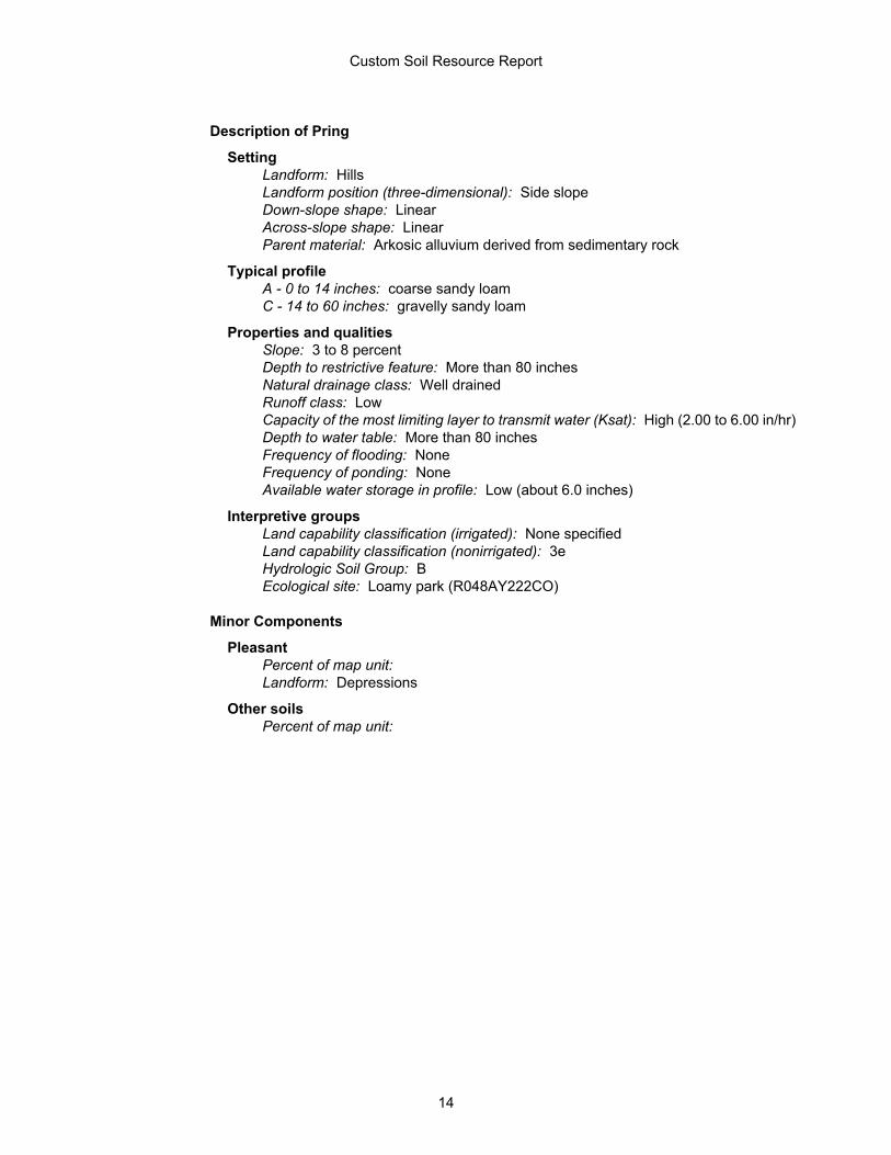
Description of Pring
SettingLandform: HillsLandform position (three-dimensional): Side slopeDown-slope shape: LinearAcross-slope shape: LinearParent material: Arkosic alluvium derived from sedimentary rock
Typical profileA - 0 to 14 inches: coarse sandy loamC - 14 to 60 inches: gravelly sandy loam
Properties and qualitiesSlope: 3 to 8 percentDepth to restrictive feature: More than 80 inchesNatural drainage class: Well drainedRunoff class: LowCapacity of the most limiting layer to transmit water (Ksat): High (2.00 to 6.00 in/hr)Depth to water table: More than 80 inchesFrequency of flooding: NoneFrequency of ponding: NoneAvailable water storage in profile: Low (about 6.0 inches)
Interpretive groupsLand capability classification (irrigated): None specifiedLand capability classification (nonirrigated): 3eHydrologic Soil Group: BEcological site: Loamy park (R048AY222CO)
Minor Components
PleasantPercent of map unit: Landform: Depressions
Other soilsPercent of map unit:
Custom Soil Resource Report
14
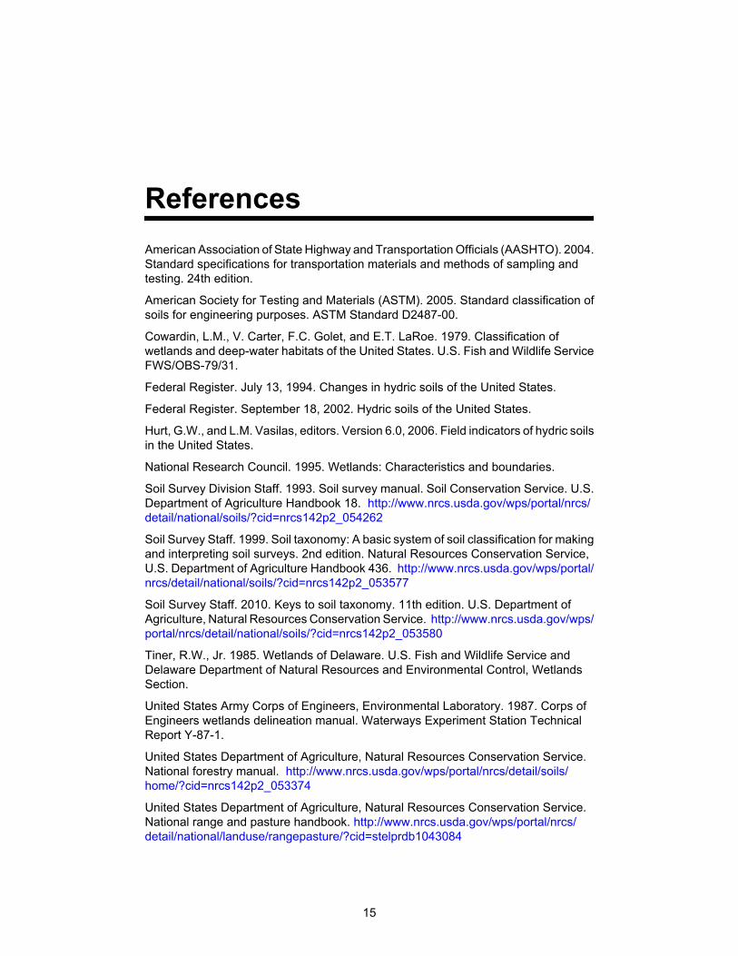
ReferencesAmerican Association of State Highway and Transportation Officials (AASHTO). 2004.Standard specifications for transportation materials and methods of sampling andtesting. 24th edition.
American Society for Testing and Materials (ASTM). 2005. Standard classification ofsoils for engineering purposes. ASTM Standard D2487-00.
Cowardin, L.M., V. Carter, F.C. Golet, and E.T. LaRoe. 1979. Classification ofwetlands and deep-water habitats of the United States. U.S. Fish and Wildlife ServiceFWS/OBS-79/31.
Federal Register. July 13, 1994. Changes in hydric soils of the United States.
Federal Register. September 18, 2002. Hydric soils of the United States.
Hurt, G.W., and L.M. Vasilas, editors. Version 6.0, 2006. Field indicators of hydric soilsin the United States.
National Research Council. 1995. Wetlands: Characteristics and boundaries.
Soil Survey Division Staff. 1993. Soil survey manual. Soil Conservation Service. U.S.Department of Agriculture Handbook 18. http://www.nrcs.usda.gov/wps/portal/nrcs/detail/national/soils/?cid=nrcs142p2_054262
Soil Survey Staff. 1999. Soil taxonomy: A basic system of soil classification for makingand interpreting soil surveys. 2nd edition. Natural Resources Conservation Service,U.S. Department of Agriculture Handbook 436. http://www.nrcs.usda.gov/wps/portal/nrcs/detail/national/soils/?cid=nrcs142p2_053577
Soil Survey Staff. 2010. Keys to soil taxonomy. 11th edition. U.S. Department ofAgriculture, Natural Resources Conservation Service. http://www.nrcs.usda.gov/wps/portal/nrcs/detail/national/soils/?cid=nrcs142p2_053580
Tiner, R.W., Jr. 1985. Wetlands of Delaware. U.S. Fish and Wildlife Service andDelaware Department of Natural Resources and Environmental Control, WetlandsSection.
United States Army Corps of Engineers, Environmental Laboratory. 1987. Corps ofEngineers wetlands delineation manual. Waterways Experiment Station TechnicalReport Y-87-1.
United States Department of Agriculture, Natural Resources Conservation Service.National forestry manual. http://www.nrcs.usda.gov/wps/portal/nrcs/detail/soils/home/?cid=nrcs142p2_053374
United States Department of Agriculture, Natural Resources Conservation Service.National range and pasture handbook. http://www.nrcs.usda.gov/wps/portal/nrcs/detail/national/landuse/rangepasture/?cid=stelprdb1043084
15
United States Department of Agriculture, Natural Resources Conservation Service.National soil survey handbook, title 430-VI. http://www.nrcs.usda.gov/wps/portal/nrcs/detail/soils/scientists/?cid=nrcs142p2_054242
United States Department of Agriculture, Natural Resources Conservation Service.2006. Land resource regions and major land resource areas of the United States, theCaribbean, and the Pacific Basin. U.S. Department of Agriculture Handbook 296.http://www.nrcs.usda.gov/wps/portal/nrcs/detail/national/soils/?cid=nrcs142p2_053624
United States Department of Agriculture, Soil Conservation Service. 1961. Landcapability classification. U.S. Department of Agriculture Handbook 210. http://www.nrcs.usda.gov/Internet/FSE_DOCUMENTS/nrcs142p2_052290.pdf
Custom Soil Resource Report
16
D:\legacy\CVR\CVR14\Drainage\CVR14 DRAINAGE APPENDIX Labels.docx B
APPENDIX B - HYDROLOGY
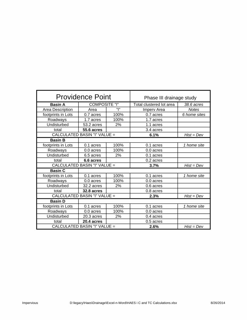
Basin A Total clustered lot area 38.6 acresArea Description Area "I" Imperv Area Notesfootprints in Lots 0.7 acres 100% 0.7 acres 6 home sites
Roadways 1.7 acres 100% 1.7 acresUndisturbed 53.2 acres 2% 1.1 acres
total 55.6 acres 3.4 acres6.1% Hist = Dev
Basin Bfootprints in Lots 0.1 acres 100% 0.1 acres 1 home site
Roadways 0.0 acres 100% 0.0 acresUndisturbed 6.5 acres 2% 0.1 acres
total 6.6 acres 0.2 acres3.7% Hist = Dev
Basin Cfootprints in Lots 0.1 acres 100% 0.1 acres 1 home site
Roadways 0.0 acres 100% 0.0 acresUndisturbed 32.2 acres 2% 0.6 acres
total 32.8 acres 0.8 acres2.3% Hist = Dev
Basin Dfootprints in Lots 0.1 acres 100% 0.1 acres 1 home site
Roadways 0.0 acres 100% 0.0 acresUndisturbed 20.3 acres 2% 0.4 acres
total 20.4 acres 0.5 acres2.6% Hist = Dev
Phase III drainage studyCOMPOSITE "I"
CALCULATED BASIN "I" VALUE =
CALCULATED BASIN "I" VALUE =
CALCULATED BASIN "I" VALUE =
CALCULATED BASIN "I" VALUE =
Providence Point
Impervious D:\legacy\Haes\Drainage\Excel-n-Word\HAES i C and TC Calculations.xlsx 8/26/2014
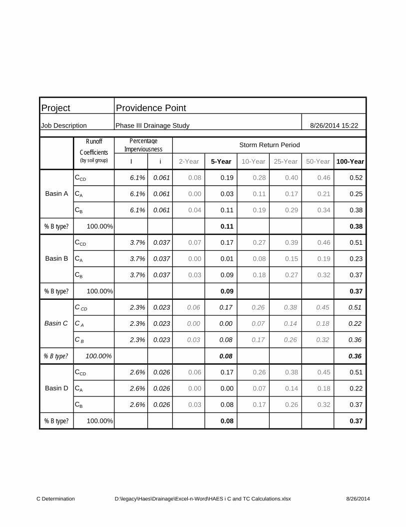
I i 2-Year 5-Year 10-Year 25-Year 50-Year 100-Year
CCD 6.1% 0.061 0.08 0.19 0.28 0.40 0.46 0.52
CA 6.1% 0.061 0.00 0.03 0.11 0.17 0.21 0.25
CB 6.1% 0.061 0.04 0.11 0.19 0.29 0.34 0.38
% B type? 100.00% 0.11 0.38
CCD 3.7% 0.037 0.07 0.17 0.27 0.39 0.46 0.51
CA 3.7% 0.037 0.00 0.01 0.08 0.15 0.19 0.23
CB 3.7% 0.037 0.03 0.09 0.18 0.27 0.32 0.37
% B type? 100.00% 0.09 0.37
C CD 2.3% 0.023 0.06 0.17 0.26 0.38 0.45 0.51
C A 2.3% 0.023 0.00 0.00 0.07 0.14 0.18 0.22
C B 2.3% 0.023 0.03 0.08 0.17 0.26 0.32 0.36
% B type? 100.00% 0.08 0.36
CCD 2.6% 0.026 0.06 0.17 0.26 0.38 0.45 0.51
CA 2.6% 0.026 0.00 0.00 0.07 0.14 0.18 0.22
CB 2.6% 0.026 0.03 0.08 0.17 0.26 0.32 0.37
% B type? 100.00% 0.08 0.37
Storm Return Period
Providence Point
Phase III Drainage Study 8/26/2014 15:22
Project
Job Description
Percentage Imperviousness
Runoff
Coefficients (by soil group)
Basin A
Basin B
Basin D
Basin C
C Determination D:\legacy\Haes\Drainage\Excel-n-Word\HAES i C and TC Calculations.xlsx 8/26/2014
Revised by: Date:
Ti Ti Tt Tt Tt Tt Ti+Tt
AREA C(5) C(100) LENGTH SLOPE Ti LENGTH SLOPE SWALE VEL Tt COMP TOTAL FINAL
Basin Ac Ft % Min L-total Ft % CODE* FPS Min Tc LENGTH Tc
Basin A 55.6 0.11 0.38 150 3.8% 14.2 2629.0 2479 5.1% 2.5 0.6 73.5 87.7 2629 n 24.6 87.7
Basin B 6.6 0.09 0.37 150 5.6% 12.8 907.0 757 6.7% 2.5 0.6 19.5 32.3 907 n 15.0 32.3
Basin C 32.8 0.08 0.36 150 8.3% 11.3 2299.0 2149 5.8% 2.5 0.6 59.6 70.8 2299 n 22.8 70.8
Basin D 20.4 0.08 0.37 150 3.0% 11.3 2056.0 1030 4.6% 2.5 0.6 73.5 87.7 2629 n 24.6 87.7
*SWALE CODES ARE:
MEADOW AND FORREST 2.50 Regional Time of Concentration Urbanized Time of ConcentrationTILLAGE 5.00
LAWN 7.00
BARE GROUND 10.00
GRASSED WATERWAY 15.00
PAVED WATERWAY 20.00
Urb
aniz
ed?
Urb
aniz
ed C
heck
Figure 7.0
Proposed Drainage BasinsStandard Form SF-2
Storm Drainage System Design
Providence PointJJM
8/26/2014 8/26/2014
3
5i
S
LC1.10.395T 10
180
LTc
Tc Determination D:\legacy\Haes\Drainage\Excel-n-Word\HAES i C and TC Calculations.xlsx 8/26/2014
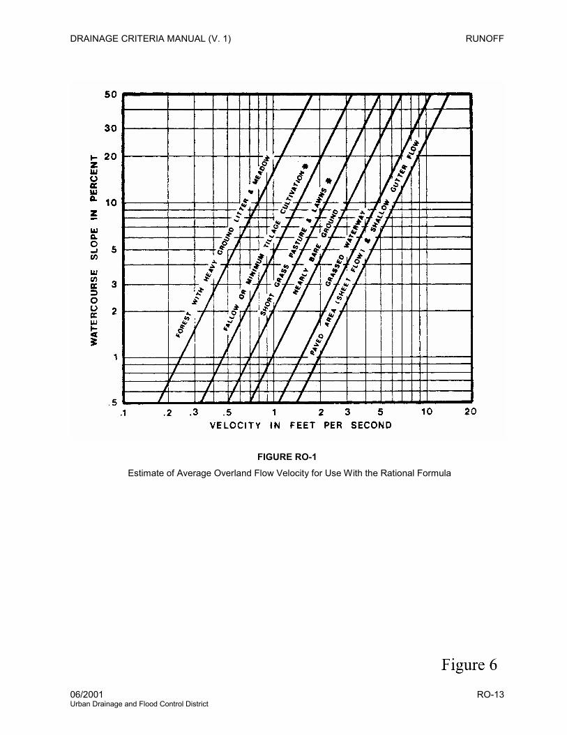
DRAINAGE CRITERIA MANUAL (V. 1) RUNOFF
06/2001 RO-13 Urban Drainage and Flood Control District
FIGURE RO-1 Estimate of Average Overland Flow Velocity for Use With the Rational Formula
Bas
in ID
Des
ign
Poin
t
Are
a
5 ye
ar R
unof
f
100
year
Run
off
Basin A 1 55.6 ac 6.7 cfs 43.3 cfs
Basin B 2 6.6 ac 1.3 cfs 9.6 cfs
Basin C 3 32.8 ac 3.5 cfs 28.0 cfs
Basin D 4 20.4 ac 1.9 cfs 15.1 cfs
Providence Point - Runoff Summary
HAES Phase II Drainage Summary in SF-3 format-Figure 7.1.xlsxSummary 1 of 3
y
Project:
Calc'd by: Date: 5 YearRevised by: (Mannings value = 0.013) P 1 : 1.43 inches
Remarks
Bas
in ID
Des
ign
Poin
t
Are
a (a
c)
Tc (M
in)
Run
off C
oeffi
cien
t C
Inte
nsity
(in/
hr)
C*A
(acr
es)
Dire
ct R
unof
f (cf
s)
Tc (M
in)
Inte
nsity
(in/
hr)
C*A
(acr
es)
Tota
l Run
off (
cfs)
Inte
rcep
ted
(cfs
)
Byp
ass
(cfs
)
Des
ign
Flow
(cfs
)
Slop
e (%
)
Pipe
Siz
e (in
ches
)
Leng
th (f
t)
Velo
city
(fps
)
Trav
el T
ime
(Min
)
(1) (2) (3) (4) (5) (6) (7) (8) (9) (10) (11) (12) (13) (14) (15) (16) (17) (18) (19) (20) (21)
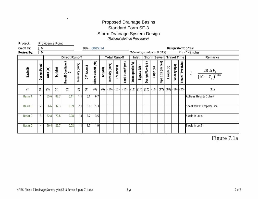
Basin A 1 55.6 87.7 0.11 1.1 6.1 6.7 At Haes Heights Culvert
Basin B 2 6.6 32.3 0.09 2.1 0.6 1.3 Sheet flow at Property Line
Basin C 3 32.8 70.8 0.08 1.3 2.7 3.5 Swale in Lot 4
Basin D 4 20.4 87.7 0.08 1.1 1.7 1.9 Swale in Lot 5
Figure 7.1a
JJM 08/27/14 Design Storm:JJM
Direct Runoff Total Runoff Inlet Storm Sewer Travel Time
Proposed Drainage BasinsStandard Form SF-3
Storm Drainage System Design(Rational Method Procedure)
Providence Point
786.01
10
5.28
cTPI
HAES Phase II Drainage Summary in SF-3 format-Figure 7.1.xlsx 5 yr 2 of 3
y
Project:
Calc'd by: Date: 100 YearRevised by: (Mannings value = 0.013) P 1 : 2.60 inches
Remarks
Bas
in ID
Des
ign
Poin
t
Are
a (a
c)
Tc (M
in)
Run
off C
oeffi
cien
t C
Inte
nsity
(in/
hr)
C*A
(acr
es)
Dire
ct R
unof
f (cf
s)
Tc (M
in)
Inte
nsity
(in/
hr)
C*A
(acr
es)
Tota
l Run
off (
cfs)
Inte
rcep
ted
(cfs
)
Byp
ass
(cfs
)
Des
ign
Flow
(cfs
)
Slop
e (%
)
Pipe
Siz
e (in
ches
)
Leng
th (f
t)
Velo
city
(fps
)
Trav
el T
ime
(Min
)
(1) (2) (3) (4) (5) (6) (7) (8) (9) (10) (11) (12) (13) (14) (15) (16) (17) (18) (19) (20) (21)
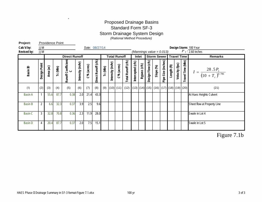
Basin A 1 55.6 87.7 0.38 2.0 21.4 43.3 At Haes Heights Culvert
Basin B 2 6.6 32.3 0.37 3.9 2.5 9.6 Sheet flow at Property Line
Basin C 3 32.8 70.8 0.36 2.3 11.9 28.0 Swale in Lot 4
Basin D 4 20.4 87.7 0.37 2.0 7.5 15.1 Swale in Lot 5
Figure 7.1b
JJM 08/27/14 Design Storm:JJM
Direct Runoff Total Runoff Inlet Storm Sewer Travel Time
Proposed Drainage BasinsStandard Form SF-3
Storm Drainage System Design(Rational Method Procedure)
Providence Point
786.01
10
5.28
cTPI
HAES Phase II Drainage Summary in SF-3 format-Figure 7.1.xlsx 100 yr 3 of 3

D:\legacy\CVR\CVR14\Drainage\CVR14 DRAINAGE APPENDIX Labels.docx C
APPENDIX C - HYDRAULICS
Culvert ReportHydraflow Express Extension for Autodesk® AutoCAD® Civil 3D® by Autodesk, Inc. Tuesday, Aug 26 2014
Circular Culvert
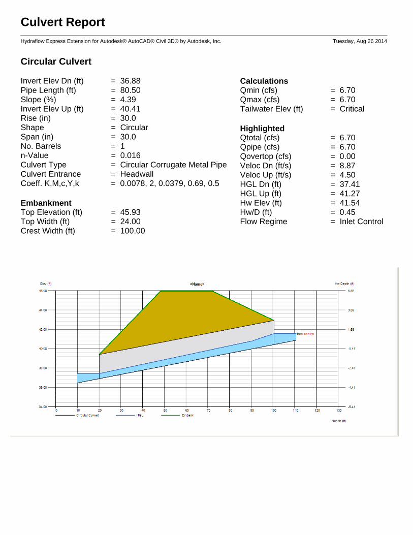
Invert Elev Dn (ft) = 36.88Pipe Length (ft) = 80.50Slope (%) = 4.39Invert Elev Up (ft) = 40.41Rise (in) = 30.0Shape = CircularSpan (in) = 30.0No. Barrels = 1n-Value = 0.016Culvert Type = Circular Corrugate Metal PipeCulvert Entrance = HeadwallCoeff. K,M,c,Y,k = 0.0078, 2, 0.0379, 0.69, 0.5
EmbankmentTop Elevation (ft) = 45.93Top Width (ft) = 24.00Crest Width (ft) = 100.00
CalculationsQmin (cfs) = 6.70Qmax (cfs) = 6.70Tailwater Elev (ft) = Critical
HighlightedQtotal (cfs) = 6.70Qpipe (cfs) = 6.70Qovertop (cfs) = 0.00Veloc Dn (ft/s) = 8.87Veloc Up (ft/s) = 4.50HGL Dn (ft) = 37.41HGL Up (ft) = 41.27Hw Elev (ft) = 41.54Hw/D (ft) = 0.45Flow Regime = Inlet Control
Culvert ReportHydraflow Express Extension for Autodesk® AutoCAD® Civil 3D® by Autodesk, Inc. Tuesday, Aug 26 2014
Circular Culvert
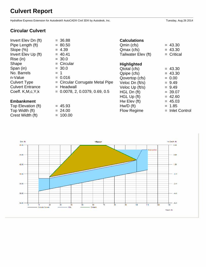
Invert Elev Dn (ft) = 36.88Pipe Length (ft) = 80.50Slope (%) = 4.39Invert Elev Up (ft) = 40.41Rise (in) = 30.0Shape = CircularSpan (in) = 30.0No. Barrels = 1n-Value = 0.016Culvert Type = Circular Corrugate Metal PipeCulvert Entrance = HeadwallCoeff. K,M,c,Y,k = 0.0078, 2, 0.0379, 0.69, 0.5
EmbankmentTop Elevation (ft) = 45.93Top Width (ft) = 24.00Crest Width (ft) = 100.00
CalculationsQmin (cfs) = 43.30Qmax (cfs) = 43.30Tailwater Elev (ft) = Critical
HighlightedQtotal (cfs) = 43.30Qpipe (cfs) = 43.30Qovertop (cfs) = 0.00Veloc Dn (ft/s) = 9.49Veloc Up (ft/s) = 9.49HGL Dn (ft) = 39.07HGL Up (ft) = 42.60Hw Elev (ft) = 45.03Hw/D (ft) = 1.85Flow Regime = Inlet Control
D:\legacy\CVR\CVR14\Drainage\CVR14 DRAINAGE APPENDIX Labels.docx E
APPENDIX E
STATE OF COLORADO
GENERAL PERMIT APPLICATION
STORMWATER
DISCHARGES ASSOCIATED WITH
CONSTRUCTION ACTIVITY
For Agency Use Only
Permit Number Assigned
COR03-
Date Received /_ /_ Month Day Year
COLORADO DISCHARGE PERMIT SYSTEM (CDPS) STORMWATER DISCHARGE ASSOCIATED WITH CONSTRUCTION ACTIVITIES APPLICATION
PHOTO COPIES, FAXED COPIES, PDF COPIES OR EMAILS WILL NOT BE ACCEPTED.
Please print or type. Original signatures are required. All items must be completed accurately and in their entirety for the application to be deemed complete. Incomplete applications will not be processed until all information is received which will ultimately delay the issuance of a permit. If more space is required to answer any question, please attach additional sheets to the application form. Applications must be submitted by mail or hand delivered to:
Colorado Department of Public Health and Environment
Water Quality Control Division
4300 Cherry Creek Drive South
WQCD-P-B2
Denver, Colorado 80246-1530
Any additional information that you would like the Division to consider in developing the permit should be provided with the application. Examples include effluent data and/or modeling and planned pollutant removal strategies.
PERMIT INFORMATION Reason for Application: NEW CERT
RENEW CERT EXISTING CERT #
Applicant is: Property Owner Contractor/Operator
A. CONTACT INFORMATION - NOT ALL CONTACT TYPES MAY APPLY * indicates required
*PERMITTEE (If more than one please add additional pages)
*ORGANIZATION FORMAL NAME: 1) *PERMITTEE the person authorized to sign and certify the permit application. This person receives all
permit correspondences and is legally responsible for compliance with the permit.
Responsible Position (Title):
Currently Held By (Person):
Telephone No:_
email address
Organization:
Mailing Address:
City:_ State: Zip: This form must be signed by the Permittee (listed in item 1) to be considered complete. Per Regulation 61 In all cases, it shall be signed as follows:
a) In the case of corporations, by a responsible corporate officer. For the purposes of this section, the responsible corporate officer is responsible for the overall operation of the facility from which the discharge described in the application originates.
b) In the case of a partnership, by a general partner. c) In the case of a sole proprietorship, by the proprietor. d) In the case of a municipal, state, or other public facility, by either a principal executive officer or ranking elected official
page 1 of 5 revised April 2011
2) DMR COGNIZANT OFFICIAL (i.e. authorized agent) the person or position authorized to sign and certify reports required by the Division including Discharge Monitoring Reports *DMR’s, Annual Reports, Compliance Schedule submittals, and other information requested by the Division. The Division will transmit pre-printed reports (ie. DMR’s) to this person. If more than one, please add additional pages. Same As 1) Permittee
Responsible Position (Title):
Currently Held By (Person):
Telephone No:_
email address
Organization:
Mailing Address:
City:_ State: Zip:
Per Regulation 61 : All reports required by permits, and other information requested by the Division shall be signed by the permittee or by a duly authorized representative of that person. A person is a duly authorized representative only if: (i) The authorization is made in writing by the permittee (ii) The authorization specifies either an individual or a position having responsibility for the overall operation of the regulated facility or activity such as the position of plant manager, operator of a well or a well field, superintendent, position of equivalent responsibility, or an individual or position having overall responsibility for environmental matters for the company. (A duly authorized representative may thus be either a named individual or any individual occupying a named position); and (iii) The written authorization is submitted to the Division
3) *SITE CONTACT local contact for questions relating to the facility & discharge authorized by this permit
for the facility. Same As 1) Permittee
Responsible Position (Title):
Currently Held By (Person):
Telephone No:_
email address
Organization:
Mailing Address:
City:_ State: Zip:
4) * BILLING CONTACT if different than the permittee
Responsible Position (Title):
Currently Held By (Person):
Telephone No:_
email address
Organization:
Mailing Address:
City:_ State: Zip:
Page 2 of 5 revised April 2011

5) OTHER CONTACT TYPES (check below) Add pages if necessary:
ResponsiblePosition (Title):
Currently Held By (Person):
Telephone No:_
email address
Organization:
Mailing Address:
City:_ State: Zip:
o Pretreatment Coordinator
o Environmental Contact o Biosolids Responsible
Party o Property Owner
Inspection Facility Contact
Consultant
Compliance Contact
Stormwater MS4 Responsible Person
Stormwater Authorized Representative
Other
B. Permitted Project/Facility Information
Project/Facility Name
Street Address or cross streets
(e.g., “S. of Park St. between 5th
Ave. and 10th
Ave.”, or “W. side of C.R. 21, 3.25 miles N. of Hwy 10”; A street name without an address, intersection, mile marker, or other identifying information describing the location of the project is not adequate. For linear projects, the route of the project should be described as best as possible with the location more accurately indicated by a map.)
City, Zip Code County
Facility Latitude/Longitude— (approximate center of site to nearest 15 seconds using one of following formats
001A Latitude . Longitude . (e.g., 39.703°, 104.933°’) degrees (to 3 decimal places) degrees (to 3 decimal places)
or
001A Latitude º ’ " Longitude º ’ " (e.g., 39°46'11"N, 104°53'11"W) degrees minutes seconds degrees minutes seconds
For the approximate center point of the property, to the nearest 15 seconds. The latitude and longitude must be provided as either degrees, minutes, and seconds, or in decimal degrees with three decimal places. This information may be obtained from a variety of sources, including: o Surveyors or engineers for the project should have, or be able to calculate, this information. o EPA maintains a web-based siting tool as part of their Toxic Release Inventory program that uses interactive maps and
aerial photography to help users get latitude and longitude. The siting tool can be accessed at www.epa.gov/tri/report/siting_tool/index.htm
o U.S. Geological Survey topographical map(s), available at area map stores. o Using a Global Positioning System (GPS) unit to obtain a direct reading. Note: the latitude/longitude required above is not the directional degrees, minutes, and seconds provided on a site legal
description to define property boundaries.
C. MAP (Attachment) If no map is submitted, the permit will not be issued.
Map: Attach a map that indicates the site location and that CLEARLY shows the boundaries of the area that will be disturbed. Maps must be no larger than 11x17 inches.
D. LEGAL DESCRIPTION
Legal description: If subdivided, provide the legal description below, or indicate that it is not applicable (do not supply
Township/Range/Section or metes and bounds description of site)
Subdivision(s): Lot(s): Block(s): OR
Not applicable (site has not been subdivided) page 3 of 5 revised April 2011
E. AREA OF CONSTRUCTION SITE
Total area of project site (acres): Area of project site to undergo disturbance (acres):
Note: aside from clearing, grading and excavation activities, disturbed areas also include areas receiving overburden (e.g., stockpiles), demolition areas, and areas with heavy equipment/vehicle traffic and storage that disturb existing vegetative cover
Total disturbed area of Larger Common Plan of Development or Sale, if applicable: (i.e., total, including all phases, filings, lots, and infrastructure not covered by this application)
Provide both the total area of the construction site, and the area that will undergo disturbance, in acres. Note: aside
from clearing, grading and excavation activities, disturbed areas also include areas receiving overburden (e.g., stockpiles), demolition areas, and areas with heavy equipment/vehicle traffic and storage that disturb existing vegetative cover (see construction activity description under the APPLICABILITY section on page 1).
If the project is part of a larger common plan of development or sale (see the definition under the APPLICABILITY section on page 1), the disturbed area of the total plan must also be included.
F. NATURE OF CONSTRUCTION ACTIVITY
Check the appropriate box(s) or provide a brief description that indicates the general nature of the construction activities. (The full description of activities must be included in the Stormwater Management Plan.)
Single Family Residential Development
Multi-Family Residential Development
Commercial Development
Oil and Gas Production and/or Exploration (including pad sites and associated infrastructure)
Highway/Road Development (not including roadways associated with commercial or residential development)
Other – Description:
G. ANTICIPATED CONSTRUCTION SCHEDULE
Construction Start Date: ___________________________ Final Stabilization Date: _____________________________
Construction Start Date - This is the day you expect to begin ground disturbing activities, including grubbing, stockpiling, excavating,
demolition, and grading activities.
Final Stabilization Date - in terms of permit coverage, this is when the site is finally stabilized. This means that all ground surface disturbing activities at the site have been completed, and all disturbed areas have been either built on, paved, or a uniform vegetative cover has been established with an individual plant density of at least 70 percent of pre-disturbance levels. Permit coverage must be maintained until the site is finally stabilized. Even if you are only doing one part of the project, the estimated final stabilization date must be for the overall project. If permit coverage is still required once your part is completed, the permit certification may be transferred or reassigned to a new responsible entity(s).
H. RECEIVING WATERS (If discharge is to a ditch or storm sewer, include the name of the ultimate receiving waters)
Immediate Receiving Water(s):
Ultimate Receiving Water(s):
Identify the receiving water of the stormwater from your site. Receiving waters are any waters of the State of Colorado. This includes all water courses, even if they are usually dry. If stormwater from the construction site enters a ditch or storm sewer system, identify that system and indicate the ultimate receiving water for the ditch or storm sewer. Note: a stormwater discharge permit does not allow a discharge into a ditch or storm sewer system without the approval of the owner/operator of that system.
page 4 of 5 revised April 2011
I. REQUIRED SIGNATURES (Both parts i. and ii. must be signed) Signature of Applicant: The applicant must be either the owner and/or operator of the construction site. Refer to Part B of the instructions for additional information.
The application must be signed by the applicant to be considered complete. In all cases, it shall be signed as follows: (Regulation 61.4 (1ei) a) In the case of corporations, by the responsible corporate officer is responsible for the overall operation of the facility from which the discharge
described in the form originates b) In the case of a partnership, by a general partner. c) In the case of a sole proprietorship, by the proprietor. d) In the case of a municipal, state, or other public facility, by either a principal executive officer, ranking elected official, (a principal executive officer
has responsibility for the overall operation of the facility from which the discharge originates).
STOP!: A Stormwater Management Plan must be completed prior to signing the following certifications!
i. STORMWATER MANAGEMENT PLAN CERTIFICATION “I certify under penalty of law that a complete Stormwater Management Plan, has been prepared for my activity. Based on my inquiry of the person or persons who manage the system, or those persons directly responsible for gathering the information, the Stormwater Management Plan is, to the best of my knowledge and belief, true, accurate, and complete. I am aware that there are significant penalties for falsely certifying the completion of said SWMP, including the possibility of fine and imprisonment for knowing violations.”
XX Signature of Legally Responsible Person or Authorized Agent (submission must include original signature) Date Signed
Name (printed) Title
ii. SIGNATURE OF PERMIT LEGAL CONTACT
"I certify under penalty of law that this document and all attachments were prepared under my direction or supervision in accordance with a system designed to assure that qualified personnel properly gather and evaluate the information submitted. Based on my inquiry of the person or persons who manage the system, or those persons directly responsible for gathering the information, the information submitted is to the best of my knowledge and belief, true, accurate and complete. I am aware that there are significant penalties for submitting false information, including the possibility of fine and imprisonment for knowing violations."
“I understand that submittal of this application is for coverage under the State of Colorado General Permit for Stormwater Discharges Associated with Construction Activity for the entirety of the construction site/project described and applied for, until such time as the application is amended or the certification is transferred, inactivated, or expired.”
XX
Signature of Legally Responsible Person (submission must include original signature) Date Signed
Name (printed Title
DO NOT INCLUDE A COPY OF THE STORMWATER MANAGEMENT PLAN DO NOT INCLUDE PAYMENT – AN INVOICE WILL BE SENT AFTER THE CERTIFICATION IS ISSUED.
page 5 of 5 revised April 2011

Inactivation Form

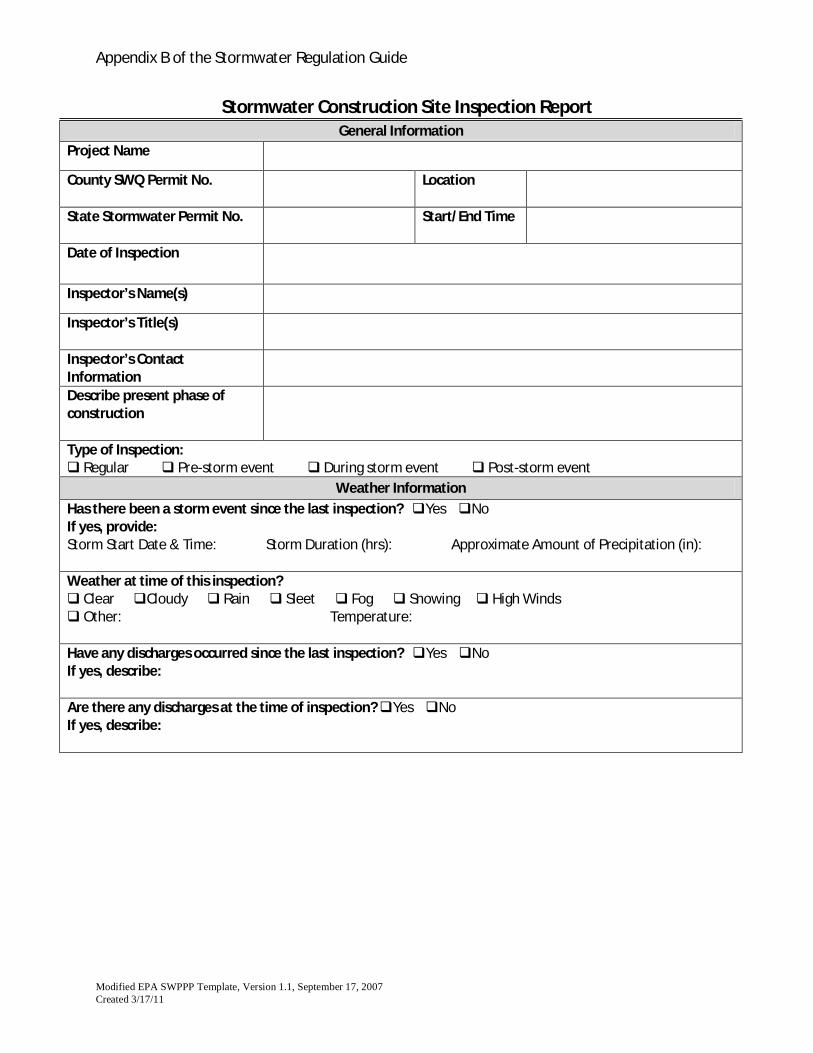
Inspection Form
Appendix B of the Stormwater Regulation Guide
Modified EPA SWPPP Template, Version 1.1, September 17, 2007Created 3/17/11
Stormwater Construction Site Inspection ReportGeneral Information
Project Name
County SWQ Permit No. Location
State Stormwater Permit No. Start/End Time
Date of Inspection
Inspector’s Name(s)
Inspector’s Title(s)
Inspector’s ContactInformationDescribe present phase ofconstruction
Type of Inspection: Regular Pre-storm event During storm event Post-storm event
Weather InformationHas there been a storm event since the last inspection? Yes NoIf yes, provide:Storm Start Date & Time: Storm Duration (hrs): Approximate Amount of Precipitation (in):
Weather at time of this inspection? Clear Cloudy Rain Sleet Fog Snowing High Winds Other: Temperature:
Have any discharges occurred since the last inspection? Yes NoIf yes, describe:
Are there any discharges at the time of inspection? Yes NoIf yes, describe:
Appendix B of the Stormwater Regulation Guide
Modified EPA SWPPP Template, Version 1.1, September 17, 2007Created 3/17/11
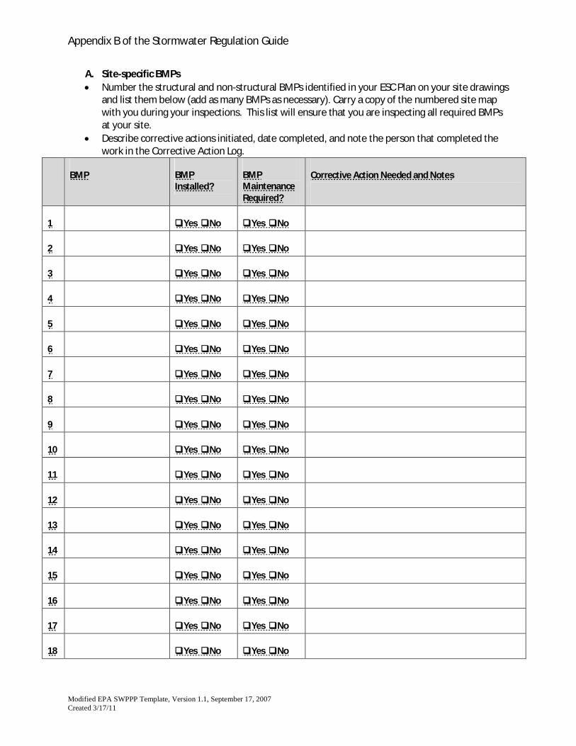
A. Site-specific BMPsNumber the structural and non-structural BMPs identified in your ESC Plan on your site drawingsand list them below (add as many BMPs as necessary). Carry a copy of the numbered site mapwith you during your inspections. This list will ensure that you are inspecting all required BMPsat your site.Describe corrective actions initiated, date completed, and note the person that completed thework in the Corrective Action Log.
BMP BMPInstalled?
BMPMaintenanceRequired?
Corrective Action Needed and Notes
1 Yes No Yes No
2 Yes No Yes No
3 Yes No Yes No
4 Yes No Yes No
5 Yes No Yes No
6 Yes No Yes No
7 Yes No Yes No
8 Yes No Yes No
9 Yes No Yes No
10 Yes No Yes No
11 Yes No Yes No
12 Yes No Yes No
13 Yes No Yes No
14 Yes No Yes No
15 Yes No Yes No
16 Yes No Yes No
17 Yes No Yes No
18 Yes No Yes No
Appendix B of the Stormwater Regulation Guide
Modified EPA SWPPP Template, Version 1.1, September 17, 2007Created 3/17/11
BMP BMPInstalled?
BMPMaintenanceRequired?
Corrective Action Needed and Notes
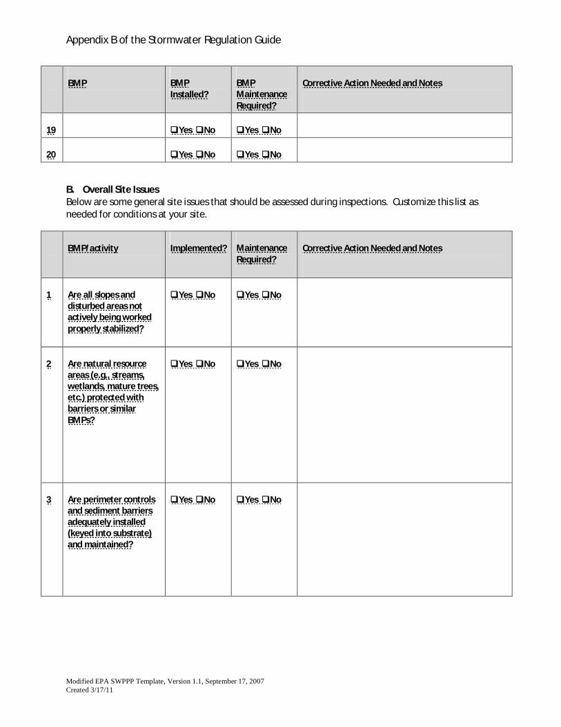
19 Yes No Yes No
20 Yes No Yes No
B. Overall Site IssuesBelow are some general site issues that should be assessed during inspections. Customize this list asneeded for conditions at your site.
BMP/activity Implemented? MaintenanceRequired?
Corrective Action Needed and Notes
1 Are all slopes anddisturbed areas notactively being workedproperly stabilized?
Yes No Yes No
2 Are natural resourceareas (e.g., streams,wetlands, mature trees,etc.) protected withbarriers or similarBMPs?
Yes No Yes No
3 Are perimeter controlsand sediment barriersadequately installed(keyed into substrate)and maintained?
Yes No Yes No
Appendix B of the Stormwater Regulation Guide
Modified EPA SWPPP Template, Version 1.1, September 17, 2007Created 3/17/11
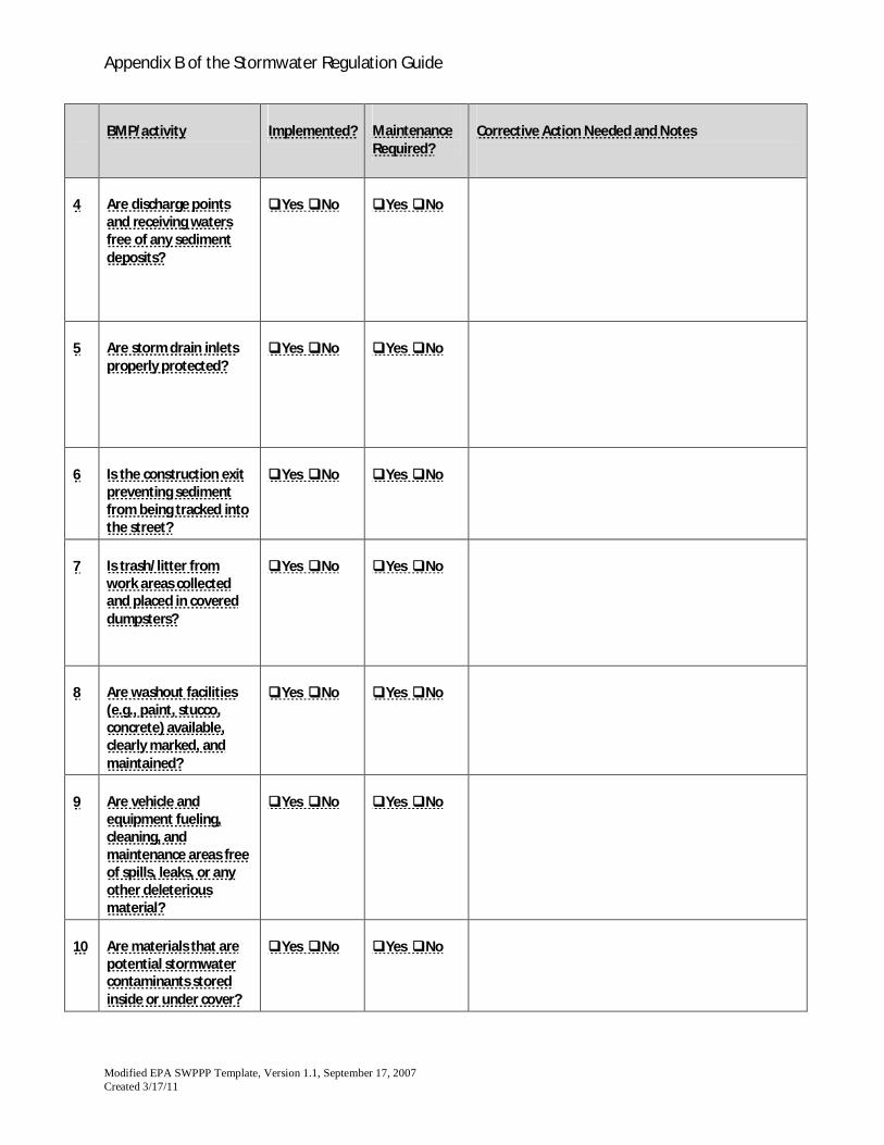
BMP/activity Implemented? MaintenanceRequired?
Corrective Action Needed and Notes
4 Are discharge pointsand receiving watersfree of any sedimentdeposits?
Yes No Yes No
5 Are storm drain inletsproperly protected?
Yes No Yes No
6 Is the construction exitpreventing sedimentfrom being tracked intothe street?
Yes No Yes No
7 Is trash/litter fromwork areas collectedand placed in covereddumpsters?
Yes No Yes No
8 Are washout facilities(e.g., paint, stucco,concrete) available,clearly marked, andmaintained?
Yes No Yes No
9 Are vehicle andequipment fueling,cleaning, andmaintenance areas freeof spills, leaks, or anyother deleteriousmaterial?
Yes No Yes No
10 Are materials that arepotential stormwatercontaminants storedinside or under cover?
Yes No Yes No
Appendix B of the Stormwater Regulation Guide
Modified EPA SWPPP Template, Version 1.1, September 17, 2007Created 3/17/11
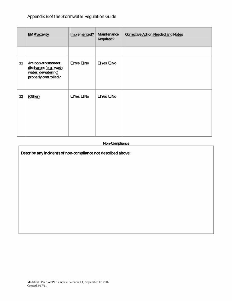
BMP/activity Implemented? MaintenanceRequired?
Corrective Action Needed and Notes
11 Are non-stormwaterdischarges (e.g., washwater, dewatering)properly controlled?
Yes No Yes No
12 (Other) Yes No Yes No
Non-Compliance
Describe any incidents of non-compliance not described above:
Appendix B of the Stormwater Regulation Guide
Modified EPA SWPPP Template, Version 1.1, September 17, 2007Created 3/17/11
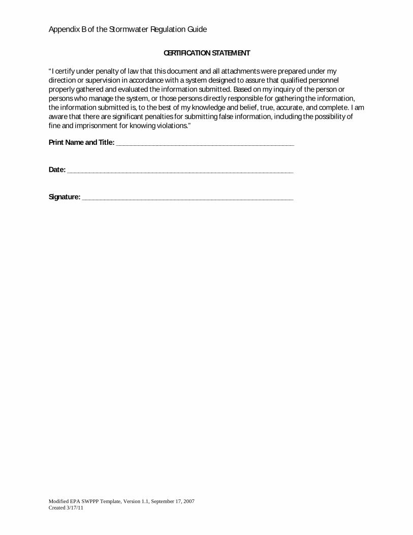
CERTIFICATION STATEMENT
“I certify under penalty of law that this document and all attachments were prepared under mydirection or supervision in accordance with a system designed to assure that qualified personnelproperly gathered and evaluated the information submitted. Based on my inquiry of the person orpersons who manage the system, or those persons directly responsible for gathering the information,the information submitted is, to the best of my knowledge and belief, true, accurate, and complete. I amaware that there are significant penalties for submitting false information, including the possibility offine and imprisonment for knowing violations.”
Print Name and Title: ________________________________________________
Date: _____________________________________________________________
Signature: _________________________________________________________
Appendix B of the Stormwater Regulation Guide
Modified EPA SWPPP Template, Version 1.1, September 17, 2007Created 3/17/11
Appendix I – ESC Plan Corrective Action Log
Project Name: _____________________________________ESC PLAN Contact: _________________________________
Amendment No. Description of the Amendment Date of Amendment Amendment Prepared by[Name(s) and Title]
Appendix B of the Stormwater Regulation Guide
Modified EPA SWPPP Template, Version 1.1, September 17, 2007Created 3/17/11
Appendix K – ESC Plan Amendment Log
Project Name: _____________________________________ESC PLAN Contact: _________________________________
Amendment No. Description of the Amendment Date of Amendment Amendment Prepared by[Name(s) and Title]