Embed Size (px)
Citation preview
µPhase® &µShapeTM
Compact and Modular Interferometers
OVERVIEW
Contents
2
Page
Fizeau Setup . . . . . . . . . . . . . . . . . . . . . . . . . . . . . . . . . . . . . . . . . . . . . . . . . . . . . . . . . . . . . . . . . 4Twyman-Green Setup . . . . . . . . . . . . . . . . . . . . . . . . . . . . . . . . . . . . . . . . . . . . . . . . . . . . . . . . . 5
µPhase® PLANO DOWN, PLANO UP & SPHERO UP . . . . . . . . . . . . . . . . . . . . . . . . . . . . . . . . . . 6µPhase® VERTICAL - Modular and Compact Interferometer . . . . . . . . . . . . . . . . . . . . . . . . . 7µPhase® UNIVERSAL 100 - The Most Flexible Interferometer . . . . . . . . . . . . . . . . . . . . . . . . . . 8µPhase® PLANO 300 - For the Measurement of Large Optics . . . . . . . . . . . . . . . . . . . . . . . . 8µPhase® Customized - Customized Interferometer Solutions . . . . . . . . . . . . . . . . . . . . . . . . . 9
µPhase® Sensors . . . . . . . . . . . . . . . . . . . . . . . . . . . . . . . . . . . . . . . . . . . . . . . . . . . . . . . . . . . . . . 18µPhase® Turnkey Solutions . . . . . . . . . . . . . . . . . . . . . . . . . . . . . . . . . . . . . . . . . . . . . . . . . . . . . 19
Applications 9
µPhase® 500 and µPhase® 1000 5
Meet TRIOPTICS Worldwide 20
µShapeTM Interferometer Software
µLens PLANO and SPHERO
10
13
Technical Data 18
µPhase® Turnkey Systems 6
Interferometry 4
µPhase® Interferometers 3
As a leading company in the field of optical test equipment, TRIOPTICS took over theµPhase® line of interferometers from FISBA OPTIK AG, Switzerland, in 2010. µPhase® per-fectly supplements the TRIOPTICS product portfolio and with TRIOPTICS worldwide sub-sidiaries and distributors µPhase® can now be offered to a wider customer base in opticaland other industries.
Close partnership with FISBA OPTIK AG enables TRIOPTICS to supply µPhase® products inusual Swiss quality and to provide service for all µPhase® products. Furthermore, the ac-quisition of FISBA OPTIK Berlin at the same time guarantees continuity in the developmentof the µShapeTM Interferometer software.
µPhase® Interferometers
3
Measuring with the Highest Accuracy
µPhase® interferometers offer objective andprecise measurement results of surface andwavefront measurements - quickly and reli-ably.
µPhase® interferometers are compact, smalland lightweight digital tools which can beused in almost any working environment.These measuring devices are perfectly com-plemented by the µShapeTM measurementand analysis software to fulfill the highest ex-pectations of quality management.
Measuring without Leaving Marks
The µPhase® Interferometer systems are usedto measure specular high precision compo-nents made of glass, plastics, metal or ce-ramics etc. The non-contact measurementmethod prevents damage to the sample un-der test, and gives the most exact evaluationof the entire surface or wavefront.
Strong Arguments for µPhase® Line of Interferometers
• Compact size and modularity enable adaptation to a variety of production and working environments
• Ultra wide measurement range of optics and surfaces with reflectivities from 0.3% to 100%
• Objective digital measurement preventshuman errors
• Well structured and comprehensive soft-ware supports both production and labora-tory use
• Unique combination of valuable features like Twyman-Green/Fizeau modes or the second camera for alignment of the lens -es provide greatest convenience using µPhase®
Modular System providing Stand-alone Inter-ferometers and Turnkey Solutions
TRIOPTICS offers µPhase® interferometers asself-contained modular parts as well as pre-defined turnkey solutions.
µPhase® customers especially appreciate thespace saving and modular concept of theµPhase® product line as it allows for flexibleand cost-effective utilization of the instru-ments. The different parts of the µPhase® in-terferometer line are all compatible and formpowerful measurement devices.
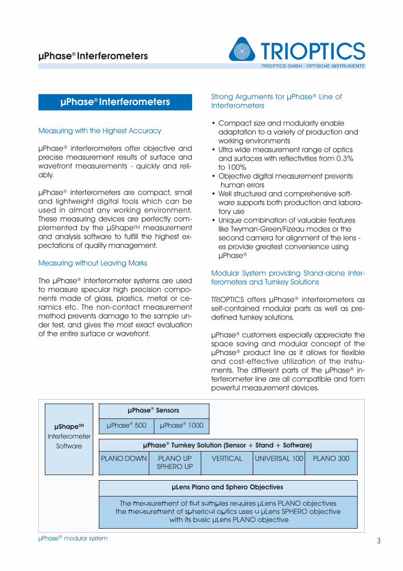
µPhase® Interferometers
µPhase® Sensors
µPhase® 500 µPhase® 1000
µLens Plano and Sphero Objectives
The measurement of flat samples requires µLens PLANO objectivesthe measurement of spherical optics uses a µLens SPHERO objective
with its basic µLens PLANO objective
µShapeTM
Interferometer
Software µPhase® Turnkey Solution (Sensor + Stand + Software)
PLANO DOWN PLANO UPSPHERO UP
VERTICAL UNIVERSAL 100 PLANO 300
µPhase® modular system
Interferometry
4
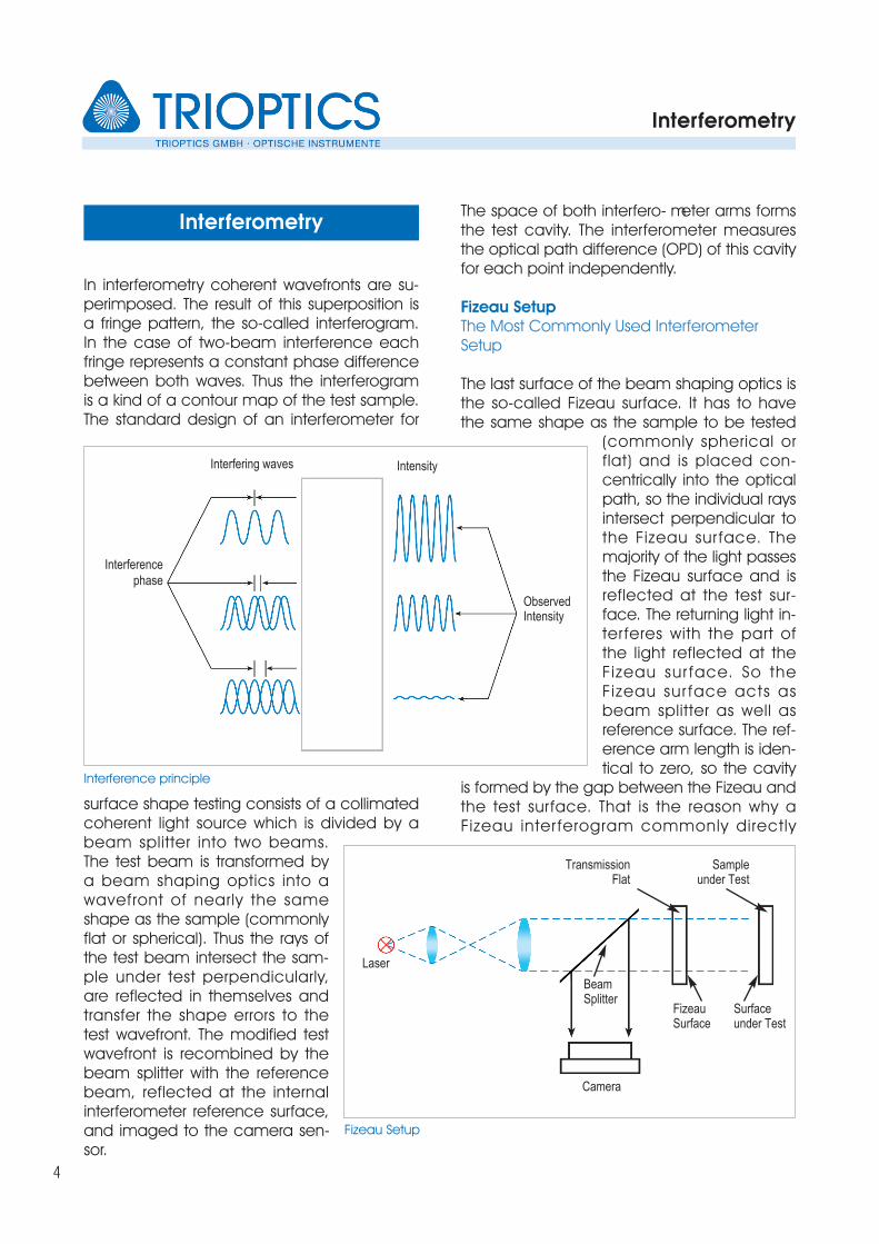
In interferometry coherent wavefronts are su-perimposed. The result of this superposition isa fringe pattern, the so-called interferogram.In the case of two-beam interference eachfringe represents a constant phase differencebetween both waves. Thus the interferogramis a kind of a contour map of the test sample. The standard design of an interferometer for
surface shape testing consists of a collimatedcoherent light source which is divided by abeam splitter into two beams.The test beam is transformed bya beam shaping optics into awavefront of nearly the sameshape as the sample (commonlyflat or spherical). Thus the rays ofthe test beam intersect the sam-ple under test perpendicularly,are reflected in themselves andtransfer the shape errors to thetest wavefront. The modified testwavefront is recombined by thebeam splitter with the referencebeam, reflected at the internalinterferometer reference surface,and imaged to the camera sen-sor.
The space of both interfero- meter arms formsthe test cavity. The interferometer measuresthe optical path difference (OPD) of this cavityfor each point independently.
Fizeau SetupThe Most Commonly Used Interferometer Setup
The last surface of the beam shaping optics isthe so-called Fizeau surface. It has to havethe same shape as the sample to be tested
(commonly spherical orflat) and is placed con-centrically into the opticalpath, so the individual raysintersect perpendicular tothe Fizeau sur face. Themajority of the light passesthe Fizeau surface and isreflected at the test sur-face. The returning light in-terferes with the part ofthe light reflected at theFizeau sur face. So theFizeau sur face acts asbeam splitter as well asreference surface. The ref-erence arm length is iden-tical to zero, so the cavity
is formed by the gap between the Fizeau andthe test surface. That is the reason why aFizeau inter ferogram commonly directly
Interference principle
Interferometry
Interfering waves Intensity
Observed Intensity
Interference
phase
Fizeau Setup
Sampleunder Test
Transmission Flat
FizeauSurface
Surfaceunder Test
Laser
Camera
Beam Splitter
Interferometry
5
shows the deviations of the test sample fromthe reference surface, i.e. Fizeau surface. Thequality of the Fizeau surface determines theaccuracy of the Fizeau interferometer. Fizeausurfaces are commonly available with a qual-ity of λ/10 – λ/20 PV, or better on request.
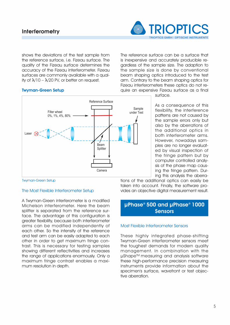
Twyman-Green Setup
The Most Flexible Interferometer Setup
A Twyman-Green interferometer is a modifiedMichelson interferometer. Here the beamsplitter is separated from the reference sur-face. The advantage of this configuration isgreater flexibility, because both interferometerarms can be modified independently ofeach other. So the intensity of the referenceand test arm can be easily adapted to each other in order to get maximum fringe con-trast. This is necessary for testing samplesshowing different reflectivities and increasesthe range of applications enormously. Only amaximum fringe contrast enables a maxi-mum resolution in depth.
The reference surface can be a surface thatis inexpensive and accurately producible re-gardless of the sample size. The adaption tothe sample size is done by conventionalbeam shaping optics introduced to the testarm. Contrary to the beam shaping optics forFizeau interferometers these optics do not re-quire an expensive Fizeau surface as a final
surface.
As a consequence of thisflexibility, the interferencepatterns are not caused bythe sample errors only butalso by the aberrations ofthe addit ional optics inboth interferometer arms.However, nowadays sam-ples are no longer evaluat-ed by visual inspection ofthe fringe pattern but bycomputer controlled analy-sis of the phase map caus-ing the fringe pattern. Dur-ing this analysis the aberra-
tions of the additional optics can easily betaken into account. Finally, the software pro-vides an objective digital measurement result.
Most Flexible Interferometer Sensors
These highly integrated phase-shift ingTwyman-Green interferometer sensors meetthe toughest demands for modern qualitymanagement. In combination with theµShapeTM measuring and analysis softwarethese high-performance precision measuringinstruments provide information about thespecimen's surface, wavefront or test objec-tive aberration.
Twyman-Green Setup
Sampleunder TestFilter wheel
0%, 1%, 4%, 80%
Laser
Camera
Reference Surface
Beam Splitter
µPhase® 500 and µPhase® 1000Sensors
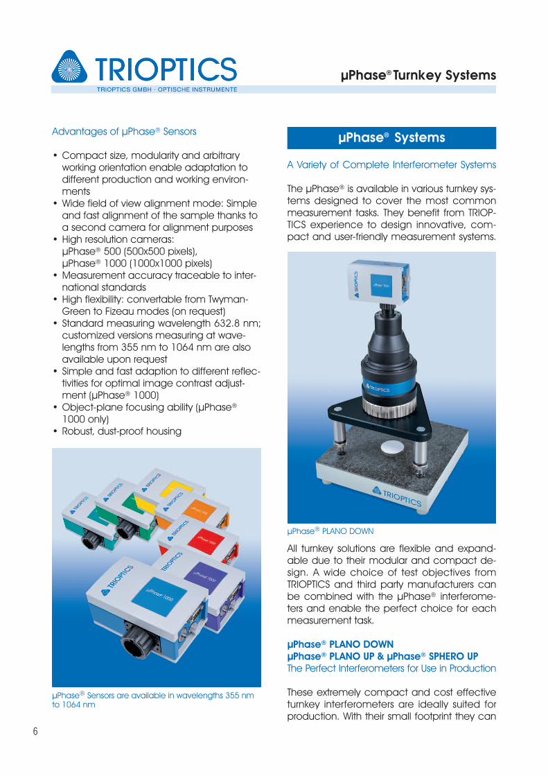
A Variety of Complete Interferometer Systems
The µPhase® is available in various turnkey sys-tems designed to cover the most commonmeasurement tasks. They benefit from TRIOP-TICS experience to design innovative, com-pact and user-friendly measurement systems.
All turnkey solutions are flexible and expand-able due to their modular and compact de-sign. A wide choice of test objectives fromTRIOPTICS and third party manufacturers canbe combined with the µPhase® interferome-ters and enable the perfect choice for eachmeasurement task.
µPhase® PLANO DOWNµPhase® PLANO UP & µPhase® SPHERO UPThe Perfect Interferometers for Use in Production
These extremely compact and cost effectiveturnkey interferometers are ideally suited forproduction. With their small footprint they can
µPhase® Turnkey Systems
6
Advantages of µPhase® Sensors
• Compact size, modularity and arbitrary working orientation enable adaptation to different production and working environ-ments
• Wide field of view alignment mode: Simple and fast alignment of the sample thanks to a second camera for alignment purposes
• High resolution cameras: µPhase® 500 (500x500 pixels), µPhase® 1000 (1000x1000 pixels)
• Measurement accuracy traceable to inter-national standards
• High flexibility: convertable from Twyman-Green to Fizeau modes (on request)
• Standard measuring wavelength 632.8 nm;customized versions measuring at wave-lengths from 355 nm to 1064 nm are also available upon request
• Simple and fast adaption to different reflec-tivities for optimal image contrast adjust-ment (µPhase® 1000)
• Object-plane focusing ability (µPhase®
1000 only) • Robust, dust-proof housing
µPhase® Sensors are available in wavelengths 355 nm to 1064 nm
µPhase® PLANO DOWN
µPhase® Systems
µPhase® Turnkey Systems
7
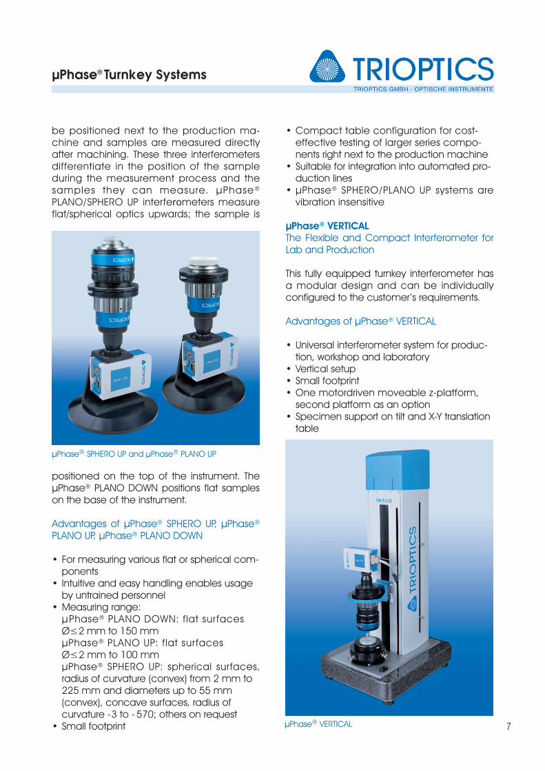
be positioned next to the production ma-chine and samples are measured directly after machining. These three interferometersdifferentiate in the position of the sample during the measurement process and the samples they can measure. µPhase®
PLANO/SPHERO UP interferometers measureflat/spherical optics upwards; the sample is
positioned on the top of the instrument. TheµPhase® PLANO DOWN positions flat sampleson the base of the instrument.
Advantages of µPhase® SPHERO UP, µPhase®
PLANO UP, µPhase® PLANO DOWN
• For measuring various flat or spherical com-ponents
• Intuitive and easy handling enables usage by untrained personnel
• Measuring range:µPhase® PLANO DOWN: flat surfaces Ø≤2 mm to 150 mmµPhase® PLANO UP: flat surfaces Ø≤2 mm to 100 mmµPhase® SPHERO UP: spherical surfaces, radius of curvature (convex) from 2 mm to 225 mm and diameters up to 55 mm (convex), concave surfaces, radius of curvature -3 to - 570; others on request
• Small footprint
• Compact table configuration for cost-effective testing of larger series compo-nents right next to the production machine
• Suitable for integration into automated pro-duction lines
• µPhase® SPHERO/PLANO UP systems are vibration insensitive
µPhase® VERTICALThe Flexible and Compact Interferometer forLab and Production
This fully equipped turnkey interferometer hasa modular design and can be individuallyconfigured to the customer’s requirements.
Advantages of µPhase® VERTICAL
• Universal interferometer system for produc-tion, workshop and laboratory
• Vertical setup • Small footprint • One motordriven moveable z-platform,
second platform as an option • Specimen support on tilt and X-Y translation
table
µPhase® SPHERO UP and µPhase® PLANO UP
µPhase® VERTICAL
µPhase® Turnkey Systems
8
• Transmission measurements possible • Unique design for all kinds of reflection &
transmission measurements• Capability of transmission measurements in
double-conjugate foci arrangement for spherical samples
• Measuring range for concave and convex spherical surfaces: Standard radius range from 1mm to 225 mm, diameter up to 55 mm with µLens PLANO 50
• Integrated radius measuring unit• Optional: Usage of CGHs for aspheric, toric
or cylindrical surface measurement• Motorized vertical z-axis • Automatic radius measurement
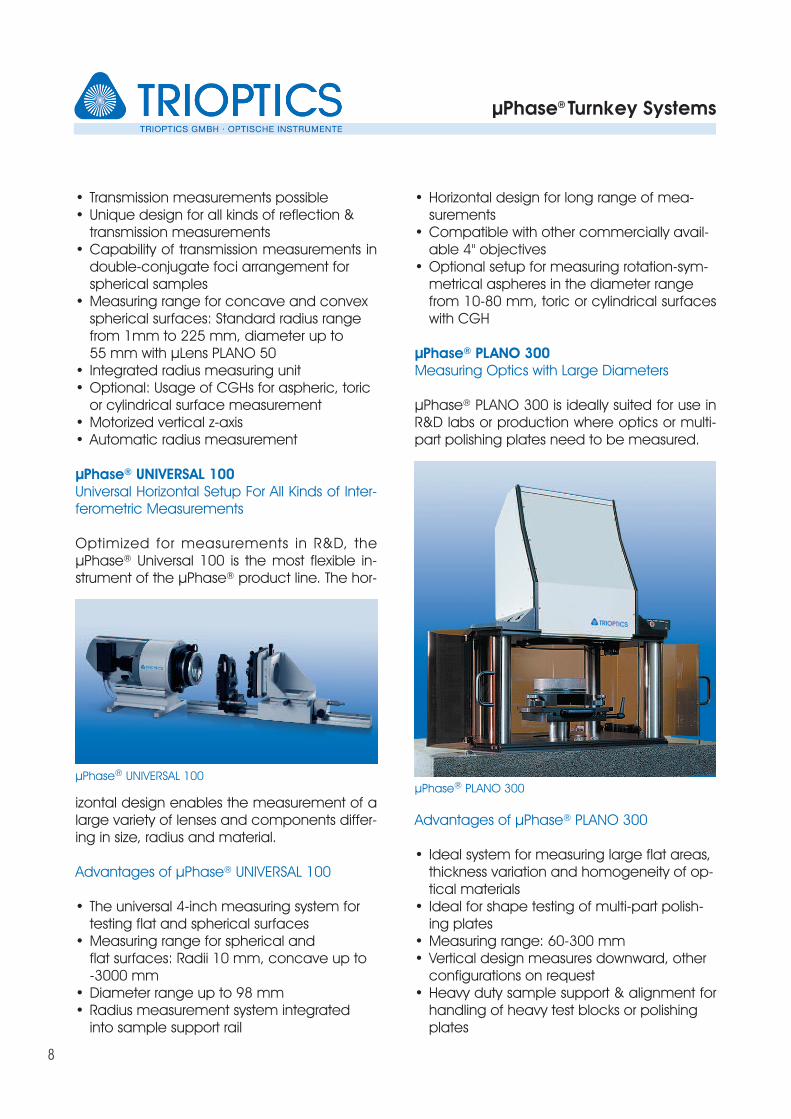
µPhase® UNIVERSAL 100Universal Horizontal Setup For All Kinds of Inter-ferometric Measurements
Optimized for measurements in R&D, theµPhase® Universal 100 is the most flexible in-strument of the µPhase® product line. The hor-
izontal design enables the measurement of alarge variety of lenses and components differ-ing in size, radius and material.
Advantages of µPhase® UNIVERSAL 100
• The universal 4-inch measuring system for testing flat and spherical surfaces
• Measuring range for spherical and flat surfaces: Radii 10 mm, concave up to -3000 mm
• Diameter range up to 98 mm• Radius measurement system integrated
into sample support rail
• Horizontal design for long range of mea-surements
• Compatible with other commercially avail-able 4" objectives
• Optional setup for measuring rotation-sym-metrical aspheres in the diameter range from 10-80 mm, toric or cylindrical surfaceswith CGH
µPhase® PLANO 300Measuring Optics with Large Diameters
µPhase® PLANO 300 is ideally suited for use inR&D labs or production where optics or multi-part polishing plates need to be measured.
Advantages of µPhase® PLANO 300
• Ideal system for measuring large flat areas, thickness variation and homogeneity of op-tical materials
• Ideal for shape testing of multi-part polish-ing plates
• Measuring range: 60-300 mm• Vertical design measures downward, other
configurations on request• Heavy duty sample support & alignment for
handling of heavy test blocks or polishing plates
µPhase® UNIVERSAL 100µPhase® PLANO 300
µPhase® Systems
9
TRIOPTICS offers extensive support for special-ized systems for applications beyond thescope of standard measuring systems. TheµPhase® is very versatile with its high modulari-ty and the compact design of the interfero -meter. This means that customized solutionsfor special measurement tasks can be imple-mented on the basis of standard compo-nents. The required components are selectedand, if required, additional made-to-measurecomponents and software modules are de-veloped by our application and software en-gineers.
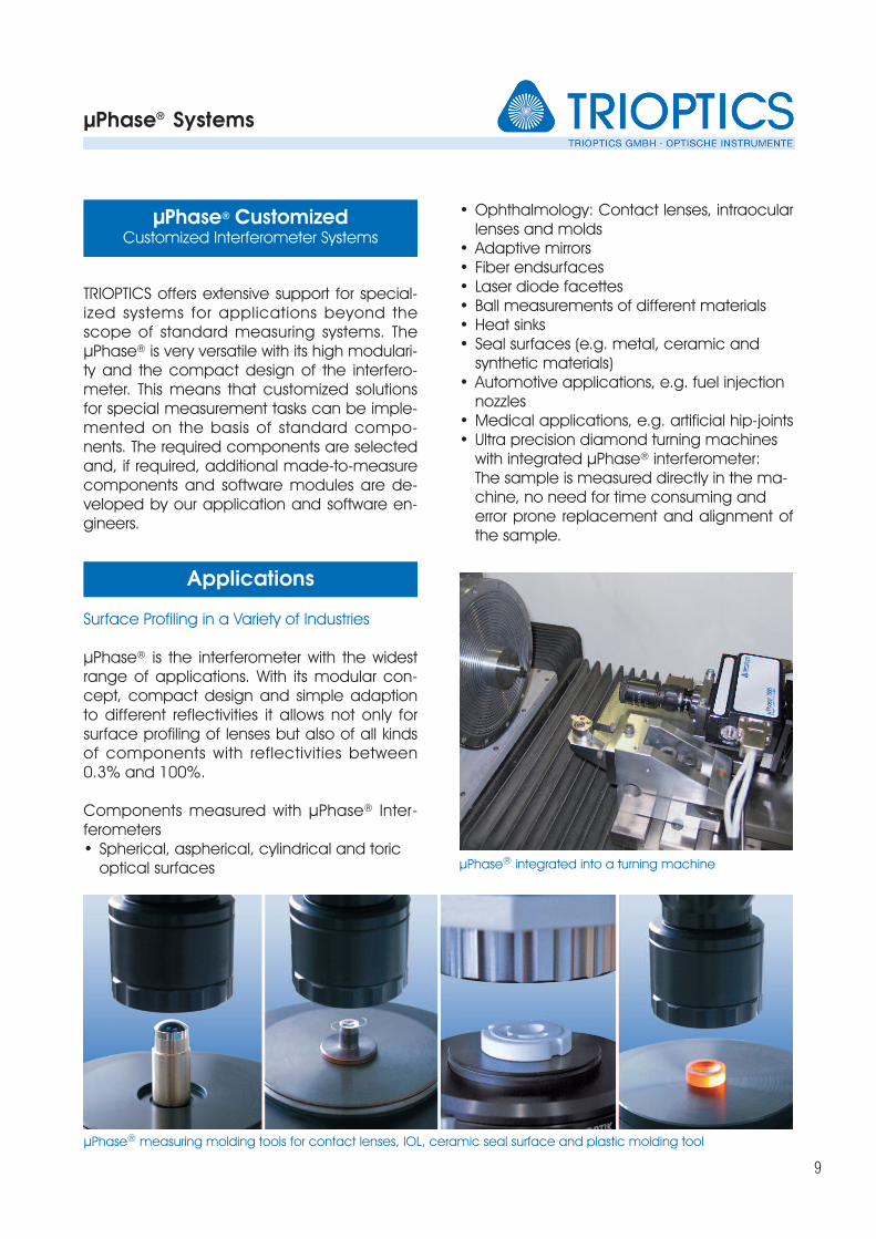
Surface Profiling in a Variety of Industries
µPhase® is the interferometer with the widestrange of applications. With its modular con-cept, compact design and simple adaptionto different reflectivities it allows not only forsurface profiling of lenses but also of all kindsof components with reflectivities between0.3% and 100%.
Components measured with µPhase® Inter -ferometers • Spherical, aspherical, cylindrical and toric
optical surfaces
• Ophthalmology: Contact lenses, intraocularlenses and molds
• Adaptive mirrors • Fiber endsurfaces • Laser diode facettes • Ball measurements of different materials • Heat sinks • Seal surfaces (e.g. metal, ceramic and
synthetic materials) • Automotive applications, e.g. fuel injection
nozzles • Medical applications, e.g. artificial hip-joints • Ultra precision diamond turning machines
with integrated µPhase® interferometer: The sample is measured directly in the ma-chine, no need for time consuming and error prone replacement and alignment of the sample.
µPhase® measuring molding tools for contact lenses, IOL, ceramic seal surface and plastic molding tool
Applications
µPhase® CustomizedCustomized Interferometer Systems
µPhase® integrated into a turning machine
µShapeTM Interferometer Software
10
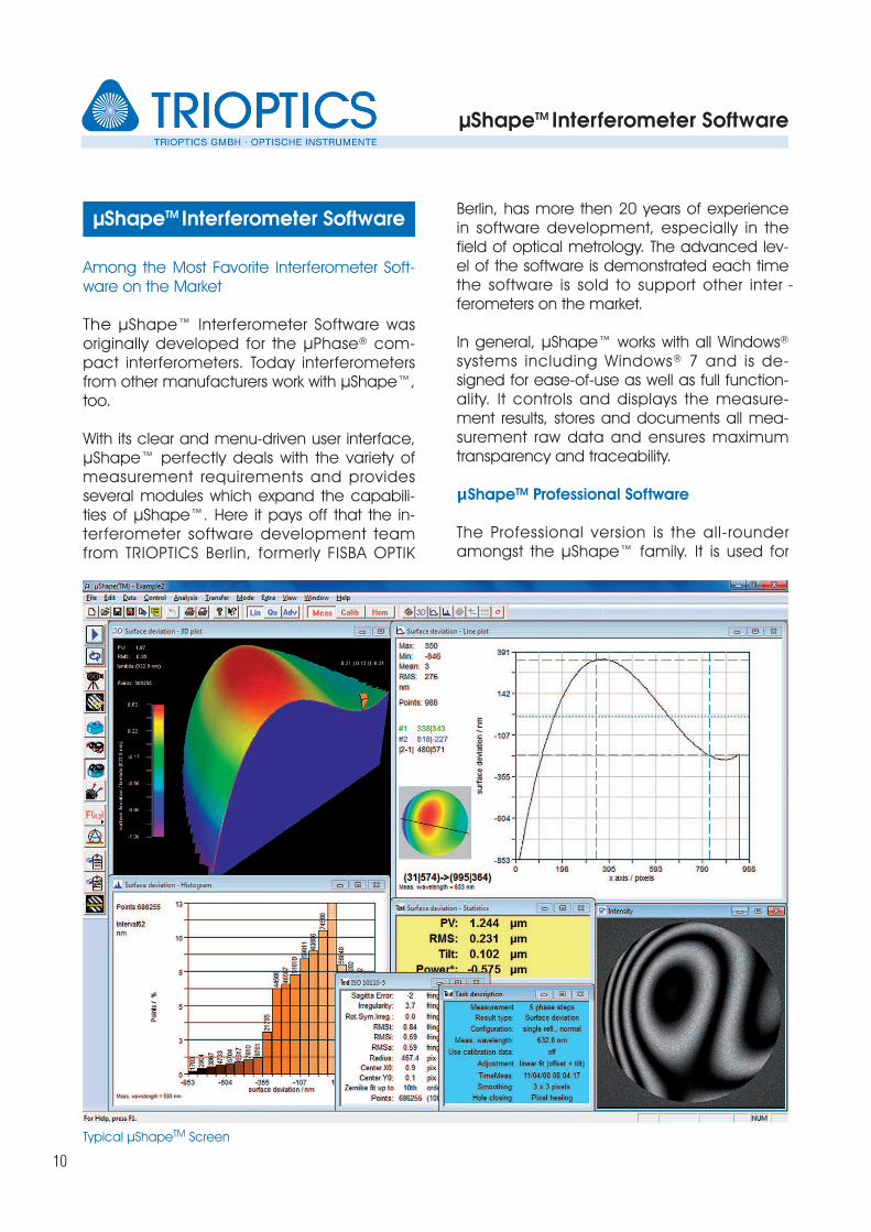
Among the Most Favorite Interferometer Soft-ware on the Market
The µShape™ Interferometer Software wasoriginally developed for the µPhase® com-pact interferometers. Today interferometersfrom other manufacturers work with µShape™,too.
With its clear and menu-driven user interface,µShape™ perfectly deals with the variety ofmeasurement requirements and providesseveral modules which expand the capabili-ties of µShape™. Here it pays off that the in-terferometer software development teamfrom TRIOPTICS Berlin, formerly FISBA OPTIK
Berlin, has more then 20 years of experiencein software development, especially in thefield of optical metrology. The advanced lev-el of the software is demonstrated each timethe software is sold to support other inter -ferometers on the market.
In general, µShape™ works with all Windows®
systems including Windows® 7 and is de-signed for ease-of-use as well as full function-ality. It controls and displays the measure-ment results, stores and documents all mea-surement raw data and ensures maximumtransparency and traceability.
μShapeTM Professional Software
The Professional version is the all-rounderamongst the µShape™ family. It is used for
µShapeTM Interferometer Software
Typical µShapeTM Screen
µShapeTM Interferometer Software
11
measuring the topography of flat, spherical,cylindrical, toric and aspherical surfaces orwavefronts and is employed in production,laboratory and research. Add-on modulesmake it possible to adapt the software to cus-tom specific demands. These modules canbe added at any time even after purchase.
The µShape™ Professional software is pre-in-stalled on a state-of-the-art PC, included withevery TRIOPTICS’ µPhase® interferometer sys-tem.
General Functions of the μShapeTM Measur-ing and Analysis Software
• Different user levels with different access rights• Shortcuts for the most used program func-
tions• Comprehensive context-sensitive online
help• Various program modes allow for the sepa-
rate visualization of calibration and measur-ing processes and their parameters with an integrated live camera image
• Automatic updates of displays and images after every change of analysis parameters and new measurement
• Easily pre-configured templates for a wide range of measuring tasks and analyses
• Storage of all parameters and settings, in-cluding window size and position, with specimen data in µShapeTM program file
• Graphic windows can be stored in several graphic formats (bmp, jpg...)
• Export of individual parameters or of select-ed data fields as text, binary or other com-mon file formats (e.g. QED, Zygo XYZ, Digi-talSurf) for external processing
• The measurement results are presented in parameters or graphically as a cross sec-tion, in 2D or 3D
• Printout of selected graphic displays or of the entire window
• Measurement log shows the results at a glance and can be widely configured in-cluding the customers logo
• Access protection and configuration of add-on modules by dongle
Basic Measuring and Calibration Settings ofμShapeTM Software
• Measuring parameters Sets measuring parameters for any given measuring configuration: choice of phase measurement method, phase computa-tion, and phase-shift wait times, separately for calibration and measurement of speci-men.
• Wavefront parametersThis function sets all parameters necessary for the computation of wavefronts, such as subtraction of calibration data; activation of various smoothing and holeclosing methods; compensation of adjustment er-rors for flat, spherical, cylindrical, aspherical and toric specimens; and geometrical op-erations (rotation, mirroring and data-field shift).
• MasksSets geometrical elements (circles, ellipses, rectangles, squares and polygons) in any combination as transparent or opaque masks
• ConfigurationSelects test setups, such as measurement of surfaces in perpendicular reflection, wavefronts in double transmission, auto-matic conversion of results and scaling of the measured field in units of length.
• VisualizationGraphic display of data fields (intensity, phase image, measured data) displayed as a cross-section, 2D or 3D image. All parameters and statistical values in table form. Display of statistics, DIN and ISO pa-rameters, Zernike and Seidel coefficients is available.
µShapeTM Interferometer Software
12
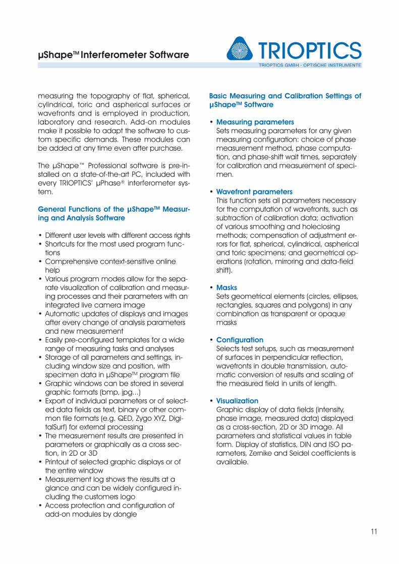
µShapeTM Add-On Modules
For extended measurement tasks and furtheranalysis the µShapeTM software offers a greatvariety of add-on modules which can beadded by the user if needed. Among theseare:
• Analysis of aspherical surfaces in spherical or CGH setups
• Analysis of cylindrical or toric surfaces
• External communication interface for con-trolling the interferometer by external pro-grams, e.g. in an automated system
• Measuring the homogeneity of glass plates
• MTF analysis of focal or afocal optical com-ponents and systems
• Measuring multiple apertures in one shot, e.g. on polishing heads
• Statistical analysis of multiple sub-apertures at the same time
• Prism and wedge measurement and analy-sis
• Considering known sample deviations, e.g. deviations caused by the optical design
• Analysis of the tool offset of lathe machines
• Analysis of wafer plates
• Roughness and PSD analysis
• Static fringe analysis for fast measurements in instable environments
Multiple apertures
Surface deviation
µShapeTM Interferometer Software
13
Special µShapeTM Versions
In cases where the powerful µShape™ Profes-sional software does not meet the customer´sneeds, TRIOPTICS offers special and cus-tomized software solutions.
µShapeTM FastFringe Software
The FastFringe Software is designed for inter-ferometers without phase-shifters. The mea-surement results are calculated by a staticfringe analysis from a single interferogram.The analysis features are ver y similar toµShapeTM Professional with only a few excep-tions not useful for non-shifting setups.
µShapeTM Customized Software
The Customized version is an individual ver-sion of the Professional Software, which isspecifically designed and created for specialcustomer needs. A variety of add-on modulesare available, making it possible to extendthe functions of the software.
Customized analysis and display functions,add-on modules or exclusive modules for cus-tomer specific measuring tasks are providedwith the customized version of the software.
µShapeTM Generic Package for Third-Party In-terferometers
The µShapeTM Generic Package can be usedwith the majority of commercial phase-mea-suring interferometers or individual interferom-eter setups.Each package includes drivers for nearly allkinds of camera interfaces and optionally apiezo-element preamplifier. Contact TRIOP-TICS for further details and an offer tailored toyour needs.
The µLens PLANO collimated test objectivesand the µLens SPHERO spherical objectivescomplement the µPhase® interferometry sys-tems and allow for increased flexibility andmodularity of the complete system.
The µLens PLANO objectives allow for mea-surements of flat surfaces or prisms in trans-mission from 2 mm - 150 mm. The µLensSPHERO spherical objectives make it possibleto test spherical and aspherical surfaces withradii up to 225 mm (convex) and 98 mm di-ameter (convex), as well as optical systems intransmission.
Further Advantages:
• Existing µPhase® systems can be expand-ed easily and at low cost thanks to the modularity and compatibility of the objec-tive design
• Testing of small samples with radii of curva-ture under 1mm is possible
• High measuring accuracy through mini-mum wavefront aberration of µPhase® and µLens SPHERO objectives
• Field of view correction allows high mea-surement certainty and interferometry with high fringe densities
Select the Appropriate Objective from theFollowing Tables
Three Steps to Your Spherical Objective
1.From the “µLens SPHERO table” choose the spherical objective which meets the re-quirement:
CXMAX > ROC > CXMIN or ROC > CC Min
µLensPLANO and SPHERO
µLens PLANO and SPHERO
14
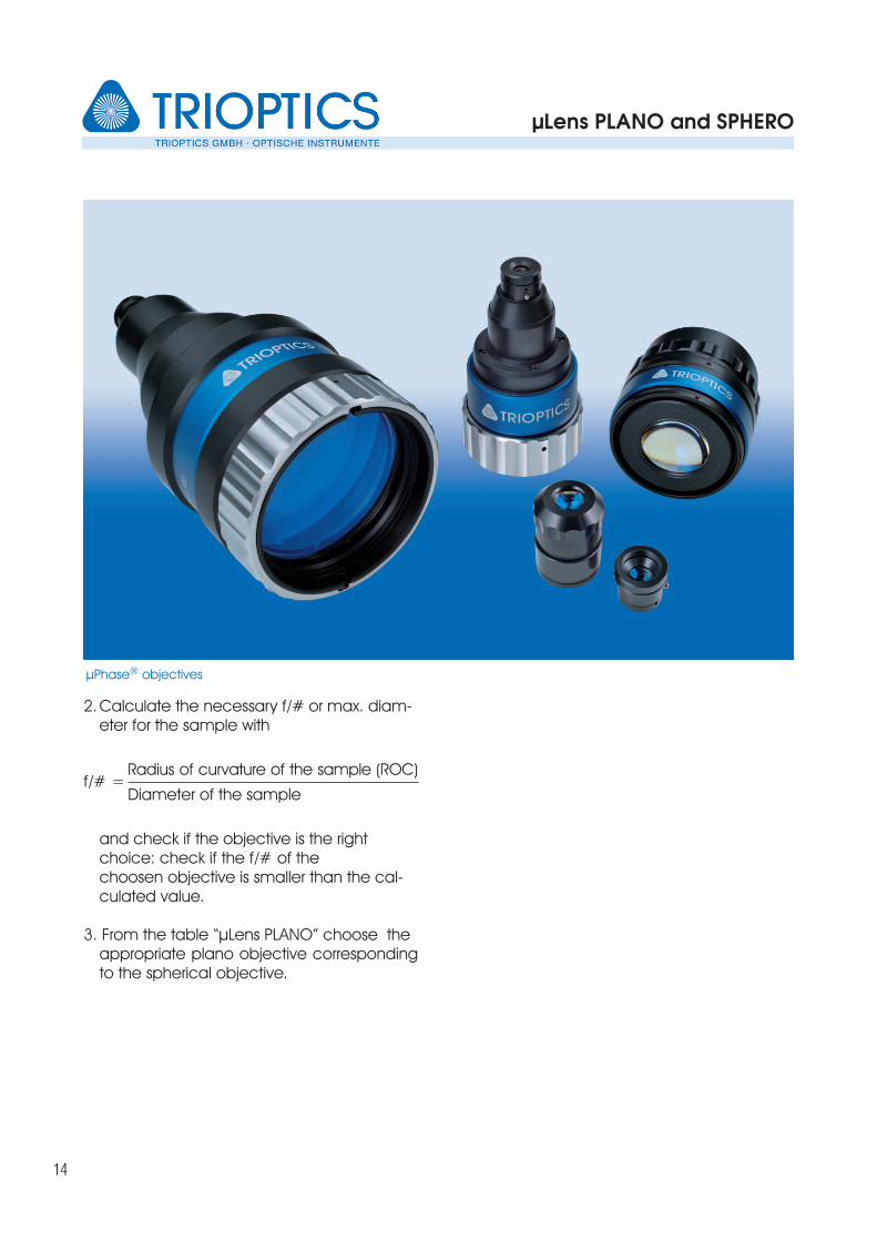
2.Calculate the necessary f/# or max. diam-eter for the sample with
Radius of curvature of the sample (ROC)
Diameter of the sample
and check if the objective is the right choice: check if the f/# of the choosen objective is smaller than the cal-culated value.
3. From the table “µLens PLANO” choose the appropriate plano objective correspondingto the spherical objective.
µPhase® objectives
f/# =
µLens PLANO and SPHERO Objectives
15
µLens® PLANO Table
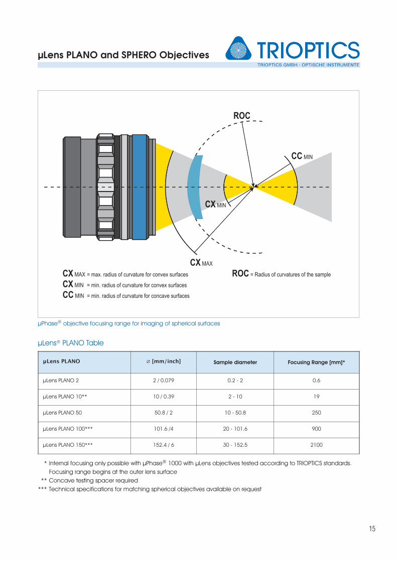
µPhase® objective focusing range for imaging of spherical surfaces
CX MAX
CX MAX = max. radius of curvature for convex surfaces
CX MIN = min. radius of curvature for convex surfaces
CC MIN = min. radius of curvature for concave surfaces
ROC = Radius of curvatures of the sample
CX MIN
CC MIN
ROC
μLens PLANO ∅ [mm/inch] Sample diameter Focusing Range [mm]*
µLens PLANO 2 2 / 0.079 0.2 - 2 0.6
µLens PLANO 10** 10 / 0.39 2 - 10 19
µLens PLANO 50 50.8 / 2 10 - 50.8 250
µLens PLANO 100*** 101.6 /4 20 - 101.6 900
µLens PLANO 150*** 152.4 / 6 30 - 152.5 2100
Internal focusing only possible with µPhase® 1000 with µLens objectives tested according to TRIOPTICS standards.
Focusing range begins at the outer lens surface
Concave testing spacer required
Technical specifications for matching spherical objectives available on request
*
**
***
µLens PLANO and SPHERO Objectives
16
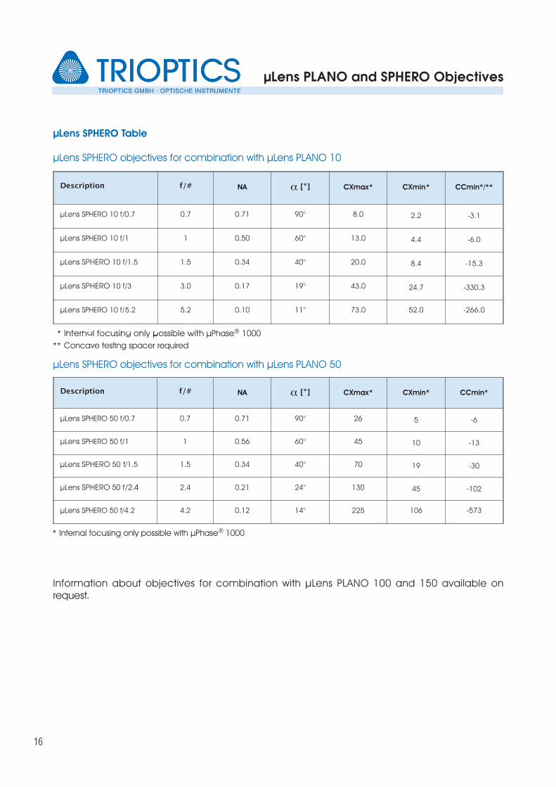
µLens SPHERO Table
µLens SPHERO objectives for combination with µLens PLANO 10
µLens SPHERO objectives for combination with µLens PLANO 50
Information about objectives for combination with µLens PLANO 100 and 150 available on request.
Description f/# NA a [ ° ] CXmax* CXmin* CCmin*/**
µLens SPHERO 10 f/0.7 0.7 0.71 90° 8.0 2.2 -3.1
µLens SPHERO 10 f/1 1 0.50 60° 13.0 4.4 -6.0
µLens SPHERO 10 f/1.5 1.5 0.34 40° 20.0 8.4 -15.3
µLens SPHERO 10 f/3 3.0 0.17 19° 43.0 24.7 -330.3
µLens SPHERO 10 f/5.2 5.2 0.10 11° 73.0 52.0 -266.0
Description f/# NA a [ ° ] CXmax* CXmin* CCmin*
µLens SPHERO 50 f/0.7 0.7 0.71 90° 26 5 -6
µLens SPHERO 50 f/1 1 0.56 60° 45 10 -13
µLens SPHERO 50 f/1.5 1.5 0.34 40° 70 19 -30
µLens SPHERO 50 f/2.4 2.4 0.21 24° 130 45 -102
µLens SPHERO 50 f/4.2 4.2 0.12 14° 225 106 -573
Internal focusing only possible with µPhase® 1000
Concave testing spacer required
*
**
Internal focusing only possible with µPhase® 1000*
µLens PLANO and SPHERO Objectives
17
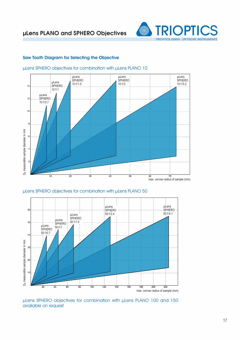
Saw Tooth Diagram for Selecting the Objective
µLens SPHERO objectives for combination with µLens PLANO 10
µLens SPHERO objectives for combination with µLens PLANO 50
µLens SPHERO50 f /2.4
µLens SPHERO50 f /4.1
µLensSPHERO10 f /0.7
µLensSPHERO10 f /1
µLensSPHERO10 f /1.5
µLensSPHERO10 f /3
max. convex radius of sample (mm)
max. convex radius of sample (mm)
µLensSPHERO10 f /5.2
µLens SPHERO objectives for combination with µLens PLANO 100 and 150available on request
DP
mea
sura
ble
sam
ple
diam
eter
in m
mD
Pm
easu
rabl
e sa
mpl
e di
amet
er in
mm
µLens SPHERO50 f /0.7
µLens SPHERO50 f /1
µLens SPHERO50 f /1.5
µPhase Technical Data
18
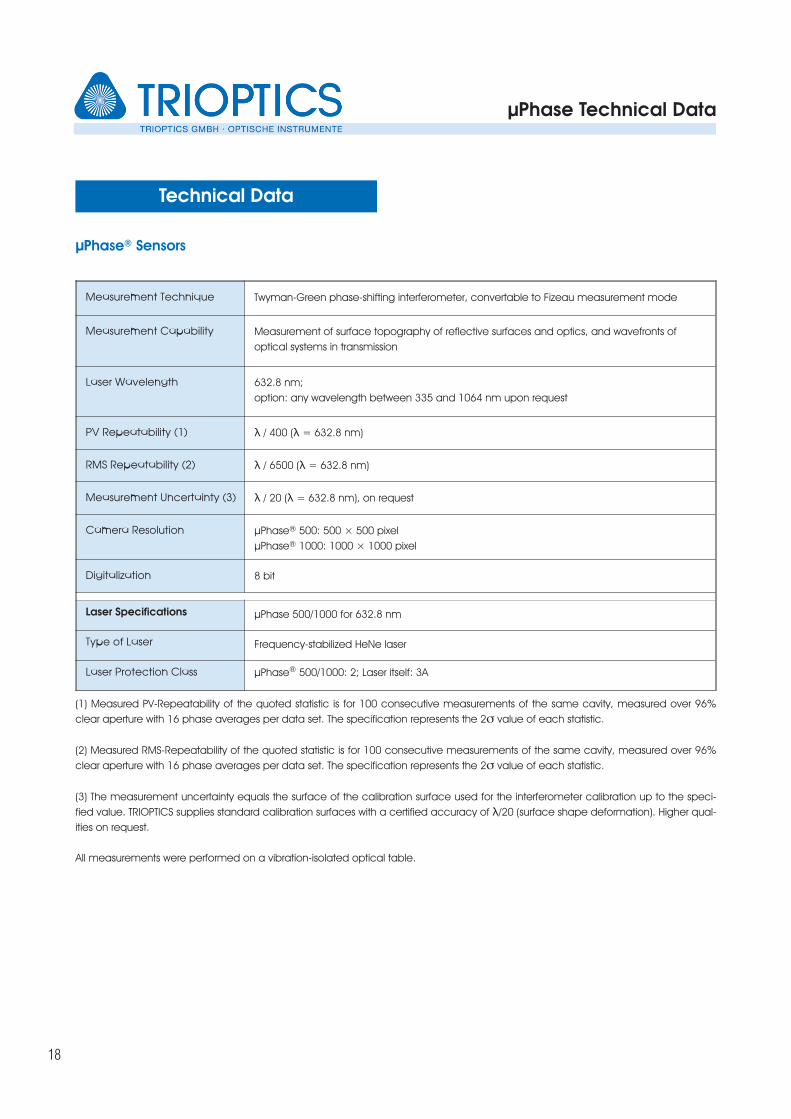
µPhase® Sensors
Measurement Technique Twyman-Green phase-shifting interferometer, convertable to Fizeau measurement mode
Measurement Capability Measurement of surface topography of reflective surfaces and optics, and wavefronts of
optical systems in transmission
Laser Wavelength 632.8 nm;
option: any wavelength between 335 and 1064 nm upon request
PV Repeatability (1) λ / 400 (λ = 632.8 nm)
RMS Repeatability (2) λ / 6500 (λ = 632.8 nm)
Measurement Uncertainty (3) λ / 20 (λ = 632.8 nm), on request
Camera Resolution µPhase® 500: 500 × 500 pixel
µPhase® 1000: 1000 × 1000 pixel
Digitalization 8 bit
Laser Specifications µPhase 500/1000 for 632.8 nm
Type of Laser Frequency-stabilized HeNe laser
Laser Protection Class µPhase® 500/1000: 2; Laser itself: 3A
Technical Data
(1) Measured PV-Repeatability of the quoted statistic is for 100 consecutive measurements of the same cavity, measured over 96%
clear aperture with 16 phase averages per data set. The specification represents the 2σ value of each statistic.
(2) Measured RMS-Repeatability of the quoted statistic is for 100 consecutive measurements of the same cavity, measured over 96%
clear aperture with 16 phase averages per data set. The specification represents the 2σ value of each statistic.
(3) The measurement uncertainty equals the surface of the calibration surface used for the interferometer calibration up to the speci-
fied value. TRIOPTICS supplies standard calibration surfaces with a certified accuracy of λ/20 (surface shape deformation). Higher qual-
ities on request.
All measurements were performed on a vibration-isolated optical table.
µPhase Configurations
19
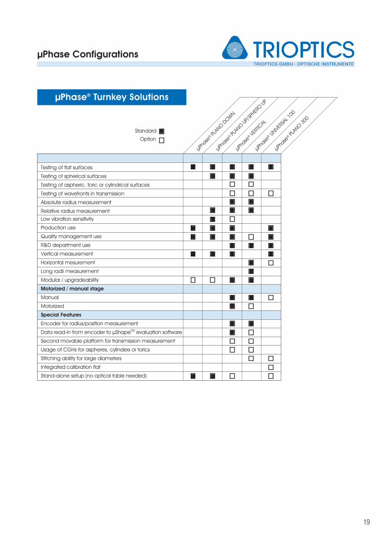
µPhase® Turnkey Solutions
µPha
se®
PLAN
O D
OW
N
µPha
se®
PLAN
O U
P/SP
HERO U
P
µPha
se®
VERT
ICAL
µPha
se®
UNIVER
SAL 1
00
µPha
se®
PLAN
O 3
00
Testing of flat surfaces
Testing of spherical surfaces
Testing of aspheric, toric or cylindrical surfaces
Testing of wavefronts in transmission
Absolute radius measurement
Relative radius measurement
Low vibration sensitivity
Production use
Quality management use
R&D department use
Vertical measurement
Horizontal mesurement
Long radii measurement
Modular / upgradeability
Motorized / manual stage
Manual
Motorized
Special Features
Encoder for radius/position measurement
Data read-in from encoder to µShapeTM evaluation software
Second movable platform for transmission measurement
Usage of CGHs for aspheres, cylinders or torics
Stitching ability for large diameters
Integrated calibration flat
Stand-alone setup (no optical table needed)
Standard
Option
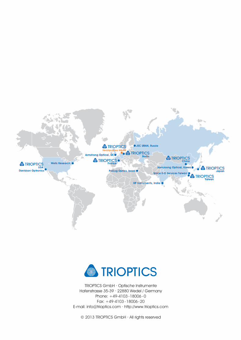
TRIOPTICS GmbH . Optische Instrumente
Hafenstrasse 35-39 . 22880 Wedel / Germany
Phone: +49-4103 -18006 -0
Fax: +49-4103 -18006-20
E-mail: [email protected] . http://www.trioptics.com
© 2013 TRIOPTICS GmbH . All rights reserved