Embed Size (px)
Citation preview
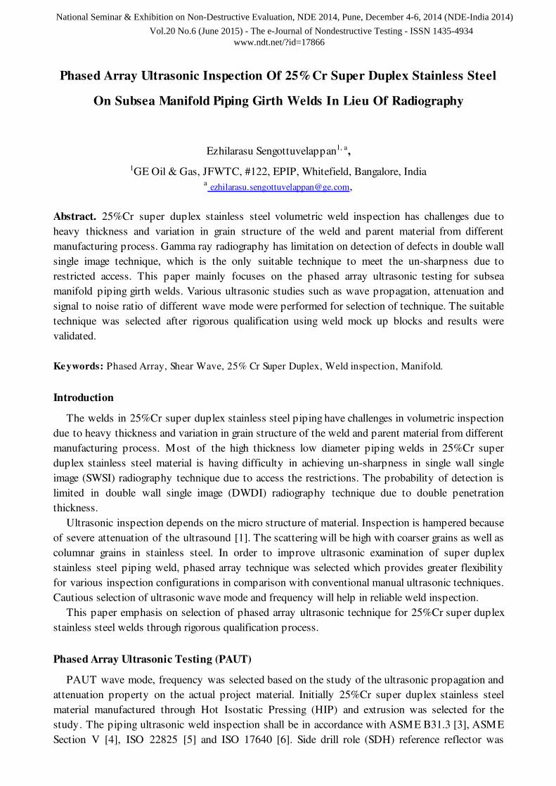
Phased Array Ultrasonic Inspection Of 25%Cr Super Duplex Stainless Steel
On Subsea Manifold Piping Girth Welds In Lieu Of Radiography
Ezhilarasu Sengottuvelappan1, a,
1GE Oil & Gas, JFWTC, #122, EPIP, Whitefield, Bangalore, India a [email protected],
Abstract. 25%Cr super duplex stainless steel volumetric weld inspection has challenges due to
heavy thickness and variation in grain structure of the weld and parent material from different
manufacturing process. Gamma ray radiography has limitation on detection of defects in double wall
single image technique, which is the only suitable technique to meet the un-sharpness due to
restricted access. This paper mainly focuses on the phased array ultrasonic testing for subsea
manifold piping girth welds. Various ultrasonic studies such as wave propagation, attenuation and
signal to noise ratio of different wave mode were performed for selection of technique. The suitable
technique was selected after rigorous qualification using weld mock up blocks and results were
validated.
Keywords: Phased Array, Shear Wave, 25% Cr Super Duplex, Weld inspection, Manifold.
Introduction
The welds in 25%Cr super duplex stainless steel piping have challenges in volumetric inspection
due to heavy thickness and variation in grain structure of the weld and parent material from different
manufacturing process. Most of the high thickness low diameter piping welds in 25%Cr super
duplex stainless steel material is having difficulty in achieving un-sharpness in single wall single
image (SWSI) radiography technique due to access the restrictions. The probability of detection is
limited in double wall single image (DWDI) radiography technique due to double penetration
thickness.
Ultrasonic inspection depends on the micro structure of material. Inspection is hampered because
of severe attenuation of the ultrasound [1]. The scattering will be high with coarser grains as well as
columnar grains in stainless steel. In order to improve ultrasonic examination of super duplex
stainless steel piping weld, phased array technique was selected which provides greater flexibility
for various inspection configurations in comparison with conventional manual ultrasonic techniques.
Cautious selection of ultrasonic wave mode and frequency will help in reliable weld inspection.
This paper emphasis on selection of phased array ultrasonic technique for 25%Cr super duplex
stainless steel welds through rigorous qualification process.
Phased Array Ultrasonic Testing (PAUT)
PAUT wave mode, frequency was selected based on the study of the ultrasonic propagation and
attenuation property on the actual project material. Initially 25%Cr super duplex stainless steel
material manufactured through Hot Isostatic Pressing (HIP) and extrusion was selected for the
study. The piping ultrasonic weld inspection shall be in accordance with ASME B31.3 [3], ASME
Section V [4], ISO 22825 [5] and ISO 17640 [6]. Side drill role (SDH) reference reflector was
National Seminar & Exhibition on Non-Destructive Evaluation, NDE 2014, Pune, December 4-6, 2014 (NDE-India 2014)
Vol.20 No.6 (June 2015) - The e-Journal of Nondestructive Testing - ISSN 1435-4934www.ndt.net/?id=17866
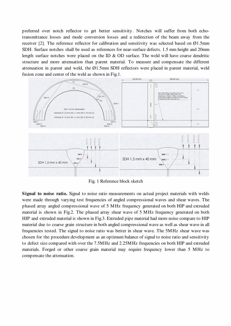
preferred over notch reflector to get better sensitivity. Notches will suffer from both echo-
transmittance losses and mode conversion losses and a redirection of the beam away from the
receiver [2]. The reference reflector for calibration and sensitivity was selected based on Ø1.5mm
SDH. Surface notches shall be used as references for near-surface defects. 1.5 mm height and 20mm
length surface notches were placed on the ID & OD surface. The weld will have coarse dendritic
structure and more attenuation than parent material. To measure and compensate the different
attenuation in parent and weld, the Ø1.5mm SDH reflectors were placed in parent material, weld
fusion zone and center of the weld as shown in Fig.1.
Fig. 1 Reference block sketch
Signal to noise ratio. Signal to noise ratio measurements on actual project materials with welds
were made through varying test frequencies of angled compressional waves and shear waves. The
phased array angled compressional wave of 5 MHz frequency generated on both HIP and extruded
material is shown in Fig.2. The phased array shear wave of 5 MHz frequency generated on both
HIP and extruded material is shown in Fig.3. Extruded pipe material had more noise compare to HIP
material due to coarse grain structure in both angled compressional wave as well as shear wave in all
frequencies tested. The signal to noise ratio was better in shear wave. The 5MHz shear wave was
chosen for the procedure development as an optimum balance of signal to noise ratio and sensitivity
to defect size compared with over the 7.5MHz and 2.25MHz frequencies on both HIP and extruded
materials. Forged or other coarse grain material may require frequency lower than 5 MHz to
compensate the attenuation.
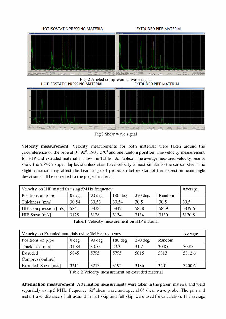
Fig. 2 Angled compresional wave signal
Fig.3 Shear wave signal
Velocity measurement. Velocity measurements for both materials were taken around the
circumference of the pipe at 00, 900, 1800, 2700 and one random position. The velocity measurement
for HIP and extruded material is shown in Table.1 & Table.2. The average measured velocity results
show the 25%Cr super duplex stainless steel have velocity almost similar to the carbon steel. The
slight variation may affect the beam angle of probe, so before start of the inspection beam angle
deviation shall be corrected to the project material.
Velocity on HIP materials using 5MHz frequency Average
Positions on pipe 0 deg. 90 deg. 180 deg. 270 deg. Random
Thickness [mm] 30.54 30.53 30.54 30.5 30.5 30.5
HIP Compression [m/s] 5841 5838 5842 5838 5839 5839.6
HIP Shear [m/s] 3128 3128 3134 3134 3130 3130.8
Table.1 Velocity measurement on HIP material
Velocity on Extruded materials using 5MHz frequency Average
Positions on pipe 0 deg. 90 deg. 180 deg. 270 deg. Random
Thickness [mm] 31.84 30.55 29.3 31.7 30.85 30.85
Extruded
Compression[m/s]
5845 5795 5795 5815 5813 5812.6
Extruded Shear [m/s] 3211 3213 3192 3186 3201 3200.6
Table.2 Velocity measurement on extruded material
Attenuation measurement. Attenuation measurements were taken in the parent material and weld
separately using 5 MHz frequency 600 shear wave and special 00 shear wave probe. The gain and
metal travel distance of ultrasound in half skip and full skip were used for calculation. The average
attenuation in HIP parent material was 0.084dB/mm and extruded parent material was 0.098dB/mm.
The average attenuation in weld material was 0.22dB/mm. The attenuation measure clearly shows
the weld have more attenuation compare to the parent material form HIP and Extruded process.
Sensitivity measurement. Sensitivity measurements were taken using the Ø1.5mm SDH placed in
the parent material, weld fusion zone and center of the weld. All the Measurements were taken on
both sides of the weld for the SDH placed in weld center. To pass the weld ultrasound requires
more dB due to the high attenuation in weldment due to the coarse grain structure. Parent Material (PM) Fusion zone Centre of weld
(Both sides)
Fusion zone by passing
sound across the weld
Depth of SDHs 1/4T 1/2T 3/4T 1/4T 1/2T 3/4T 1/4T 1/2T 3/4T 1/4T 1/2T 3/4T
HIP Upstream (dB)
Downstream (dB)
55.7 50.3 45.6 51.2 50.8 50.3
54.2
53.4
51.2
54.7
44.4
53.3
64.2 55.0 50.4
Extruded Upstream
Downstream (dB)
58.1 55.5 45.9 60.6 56.7
53.5 68.2
66.2
60.8
61.9
57.6
52.0
68.3 54.8 51.9
Table.3 Sensitivity measurement
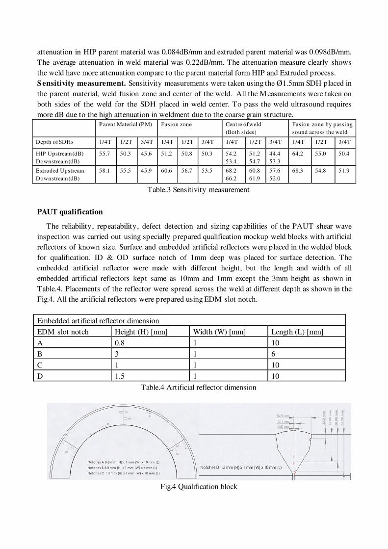
PAUT qualification
The reliability, repeatability, defect detection and sizing capabilities of the PAUT shear wave
inspection was carried out using specially prepared qualification mockup weld blocks with artificial
reflectors of known size. Surface and embedded artificial reflectors were placed in the welded block
for qualification. ID & OD surface notch of 1mm deep was placed for surface detection. The
embedded artificial reflector were made with different height, but the length and width of all
embedded artificial reflectors kept same as 10mm and 1mm except the 3mm height as shown in
Table.4. Placements of the reflector were spread across the weld at different depth as shown in the
Fig.4. All the artificial reflectors were prepared using EDM slot notch.
Embedded artificial reflector dimension
EDM slot notch Height (H) [mm] Width (W) [mm] Length (L) [mm]
A 0.8 1 10
B 3 1 6
C 1 1 10
D 1.5 1 10
Table.4 Artificial reflector dimension
Fig.4 Qualification block
Scanning of qualification block. The qualification blocks with artificial reflectors were scanned
with PAUT shear wave full skip technique. For the inspection 64 and 32 elements probe were used
with 5 MHz frequency was selected as per the signal to noise ratio study. The scan plans were
prepared using ES beam tool software version 5. Single line scan from either side of the weld were
selected with different sectorial and linear groups in scan plan. Pseudo tandem technique was
selected to cover the fusion zone on the 100 weld bevel at the top surface only in 64 elements probe.
Blind trails. Four 8” diameter and 30mm thickness welded 25%Cr super duplex stainless joints
with V bevel configuration were taken for blind trails. The joints were radiographed with DWDI
technique and no significant indication found. Then joint were scanned with PAUT.
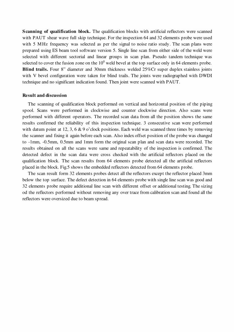
Result and discussion
The scanning of qualification block performed on vertical and horizontal position of the piping
spool. Scans were performed in clockwise and counter clockwise direction. Also scans were
performed with different operators. The recorded scan data from all the position shows the same
results confirmed the reliability of this inspection technique. 3 consecutive scan were performed
with datum point at 12, 3, 6 & 9 o’clock positions. Each weld was scanned three times by removing
the scanner and fixing it again before each scan. Also index offset position of the probe was changed
to -1mm, -0.5mm, 0.5mm and 1mm form the original scan plan and scan data were recorded. The
results obtained on all the scans were same and repeatability of the inspection is confirmed. The
detected defect in the scan data were cross checked with the artificial reflectors placed on the
qualification block. The scan results from 64 elements probe detected all the artificial reflectors
placed in the block. Fig.5 shows the embedded reflectors detected from 64 elements probe.
The scan result form 32 elements probes detect all the reflectors except the reflector placed 3mm
below the top surface. The defect detection in 64 elements probe with single line scan was good and
32 elements probe require additional line scan with different offset or additional testing. The sizing
od the reflectors performed without removing any over trace from calibration scan and found all the
reflectors were oversized due to beam spread.
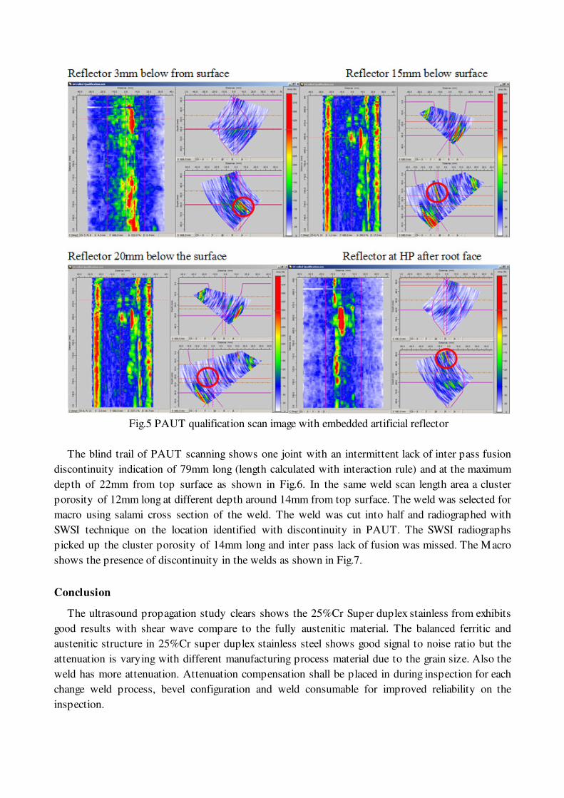
Fig.5 PAUT qualification scan image with embedded artificial reflector
The blind trail of PAUT scanning shows one joint with an intermittent lack of inter pass fusion
discontinuity indication of 79mm long (length calculated with interaction rule) and at the maximum
depth of 22mm from top surface as shown in Fig.6. In the same weld scan length area a cluster
porosity of 12mm long at different depth around 14mm from top surface. The weld was selected for
macro using salami cross section of the weld. The weld was cut into half and radiographed with
SWSI technique on the location identified with discontinuity in PAUT. The SWSI radiographs
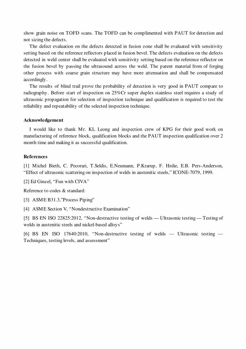
picked up the cluster porosity of 14mm long and inter pass lack of fusion was missed. The Macro
shows the presence of discontinuity in the welds as shown in Fig.7.
Conclusion
The ultrasound propagation study clears shows the 25%Cr Super duplex stainless from exhibits
good results with shear wave compare to the fully austenitic material. The balanced ferritic and
austenitic structure in 25%Cr super duplex stainless steel shows good signal to noise ratio but the
attenuation is varying with different manufacturing process material due to the grain size. Also the
weld has more attenuation. Attenuation compensation shall be placed in during inspection for each
change weld process, bevel configuration and weld consumable for improved reliability on the
inspection.
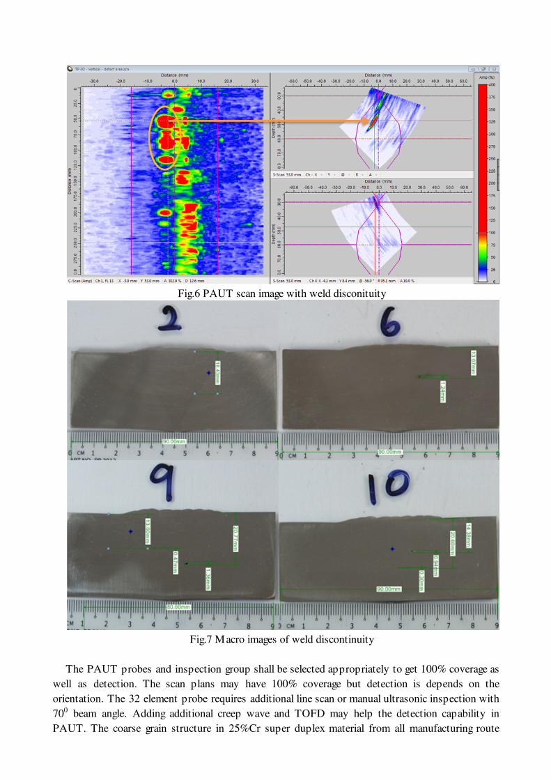
Fig.6 PAUT scan image with weld disconituity
Fig.7 Macro images of weld discontinuity
The PAUT probes and inspection group shall be selected appropriately to get 100% coverage as
well as detection. The scan plans may have 100% coverage but detection is depends on the
orientation. The 32 element probe requires additional line scan or manual ultrasonic inspection with
700 beam angle. Adding additional creep wave and TOFD may help the detection capability in
PAUT. The coarse grain structure in 25%Cr super duplex material from all manufacturing route
show grain noise on TOFD scans. The TOFD can be complimented with PAUT for detection and
not sizing the defects.
The defect evaluation on the defects detected in fusion zone shall be evaluated with sensitivity
setting based on the reference reflectors placed in fusion bevel. The defects evaluation on the defects
detected in weld center shall be evaluated with sensitivity setting based on the reference reflector on
the fusion bevel by passing the ultrasound across the weld. The parent material from of forging
other process with coarse grain structure may have more attenuation and shall be compensated
accordingly.
The results of blind trail prove the probability of detection is very good in PAUT compare to
radiography. Before start of inspection on 25%Cr super duplex stainless steel requires a study of
ultrasonic propagation for selection of inspection technique and qualification is required to test the
reliability and repeatability of the selected inspection technique.
Acknowledgement
I would like to thank Mr. KL Leong and inspection crew of KPG for their good work on
manufacturing of reference block, qualification blocks and the PAUT inspection qualification over 2
month time and making it as successful qualification.
References
[1] Michel Bieth, C. Pecorari, T.Seldis, E.Neumann, P.Krarup, F. Hrdie, E.B. Pers-Anderson,
“Effect of ultrasonic scattering on inspection of welds in austenitic steels,” ICONE-7079, 1999.
[2] Ed Ginzel, “Fun with CIVA”
Reference to codes & standard:
[3] ASME B31.3,”Process Piping”
[4] ASME Section V, “Nondestructive Examination”
[5] BS EN ISO 22825:2012, “Non-destructive testing of welds — Ultrasonic testing — Testing of
welds in austenitic steels and nickel-based alloys”
[6] BS EN ISO 17640:2010, “Non-destructive testing of welds — Ultrasonic testing —
Techniques, testing levels, and assessment”