Embed Size (px)
DESCRIPTION
Phased Refurbishment of Relays and Communication Channels. Traditional panel with analogue relays and traditional control. Modern panel with numerical multi-function relay. Communication Channel Options. DCE. DCE. DCE. DCE. DCE. DCE. DCE. DCE. Dedicated channel FO shared - PowerPoint PPT Presentation
Citation preview
1G. Koch D Session 3 – Block 3 – paper 3.68 update
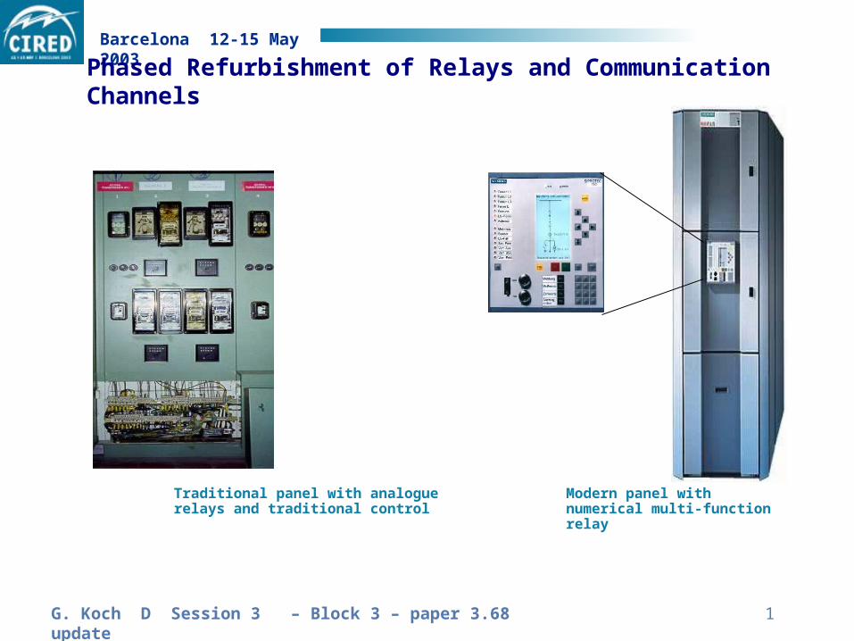
Barcelona 12-15 May 2003
Traditional panel with analogue relays and traditional control
Modern panel with numerical multi-function relay
Phased Refurbishment of Relays and Communication Channels
2G. Koch D Session 3 – Block 3 – paper 3.68 update
Barcelona 12-15 May 2003
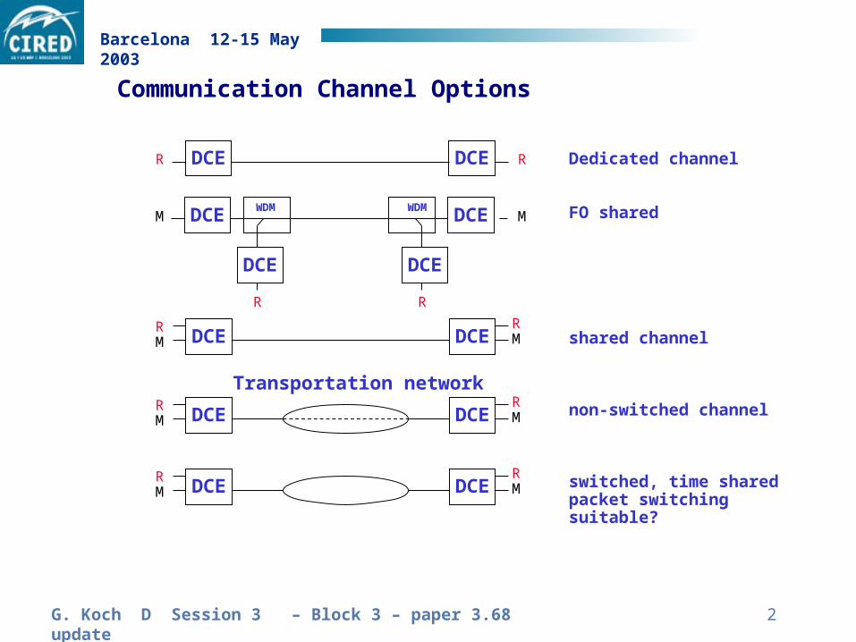
DCE DCE
DCE DCERM
RM
RR
DCE DCERM
RM
DCE DCERM
RM
Dedicated channel
FO shared
shared channel
non-switched channel
switched, time sharedpacket switching suitable?
Transportation network
DCE DCE MM
DCE DCE
WDM WDM
R R
Communication Channel Options
3G. Koch D Session 3 – Block 3 – paper 3.68 update
Barcelona 12-15 May 2003
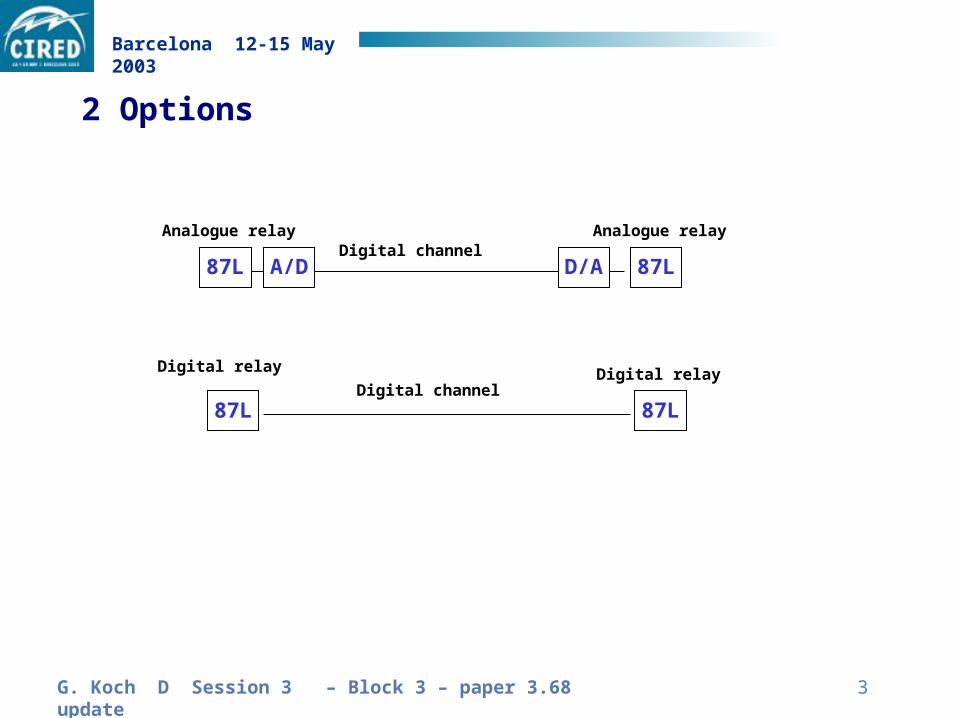
2 Options
A/D D/A
87L 87L
Digital channel
Digital channel
87L87L
Digital relay Digital relay
Analogue relay Analogue relay
4G. Koch D Session 3 – Block 3 – paper 3.68 update
Barcelona 12-15 May 2003
%
I
O
V
0 50 100
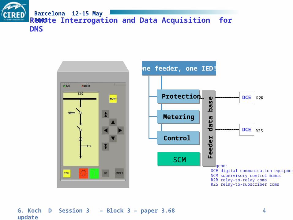
Legend:DCE digital communication equipmentSCM supervisory control mimicR2R relay-to-relay comsR2S relay-to-subscriber coms
One feeder, one IED!
Protection
Metering
Control
Fee
der
dat
a b
ase
DCE
SCM
DCE R2R
R2S
Remote Interrogation and Data Acquisition for DMS
5G. Koch D Session 3 – Block 3 – paper 3.68 update
Barcelona 12-15 May 2003
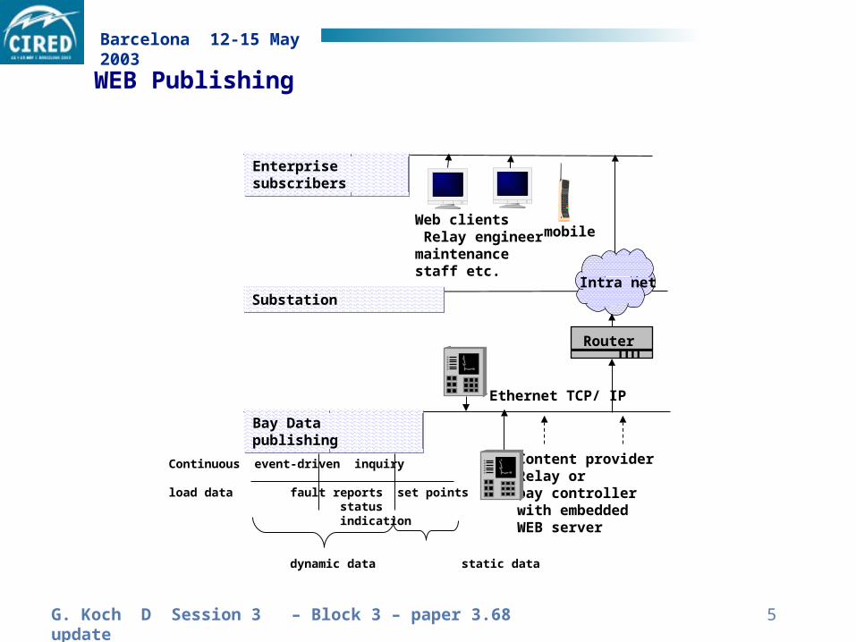
Bay Data publishingBay Data publishing
Enterprise subscribersEnterprise subscribers
Content providerRelay orbay controllerwith embeddedWEB server
Continuous event-driven inquiry
load data fault reports set points status indication
dynamic data static data
Web clients Relay engineermaintenance staff etc.
Ethernet TCP/ IP
Substation Substation
Router
Intra net
mobile
WEB Publishing
6G. Koch D Session 3 – Block 3 – paper 3.68 update
Barcelona 12-15 May 2003
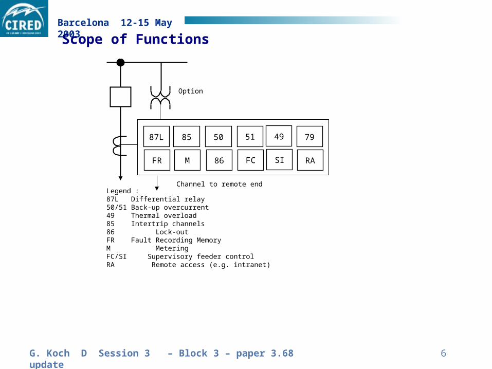
Scope of Functions
Channel to remote endLegend : 87L Differential relay50/51 Back-up overcurrent49 Thermal overload 85 Intertrip channels86 Lock-outFR Fault Recording MemoryM MeteringFC/SI Supervisory feeder controlRA Remote access (e.g. intranet)
508587L 51 49 79
86MFR FC SI RA
Option
7G. Koch D Session 3 – Block 3 – paper 3.68 update
Barcelona 12-15 May 2003
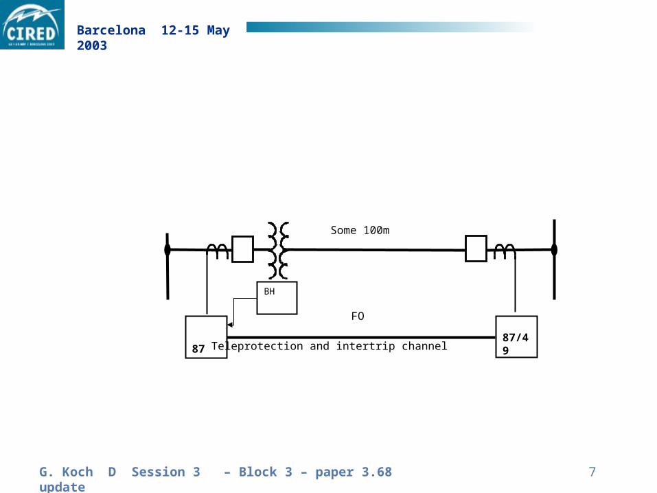
87/49 87
FO
BH
Teleprotection and intertrip channel
Some 100m
8G. Koch D Session 3 – Block 3 – paper 3.68 update
Barcelona 12-15 May 2003
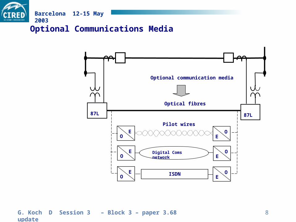
87L 87L
EO
OE
EO
OE
EO
OE
Digital Coms network
ISDN
Optical fibres
Pilot wires
Optional communication media
Optional Communications Media
9G. Koch D Session 3 – Block 3 – paper 3.68 update
Barcelona 12-15 May 2003
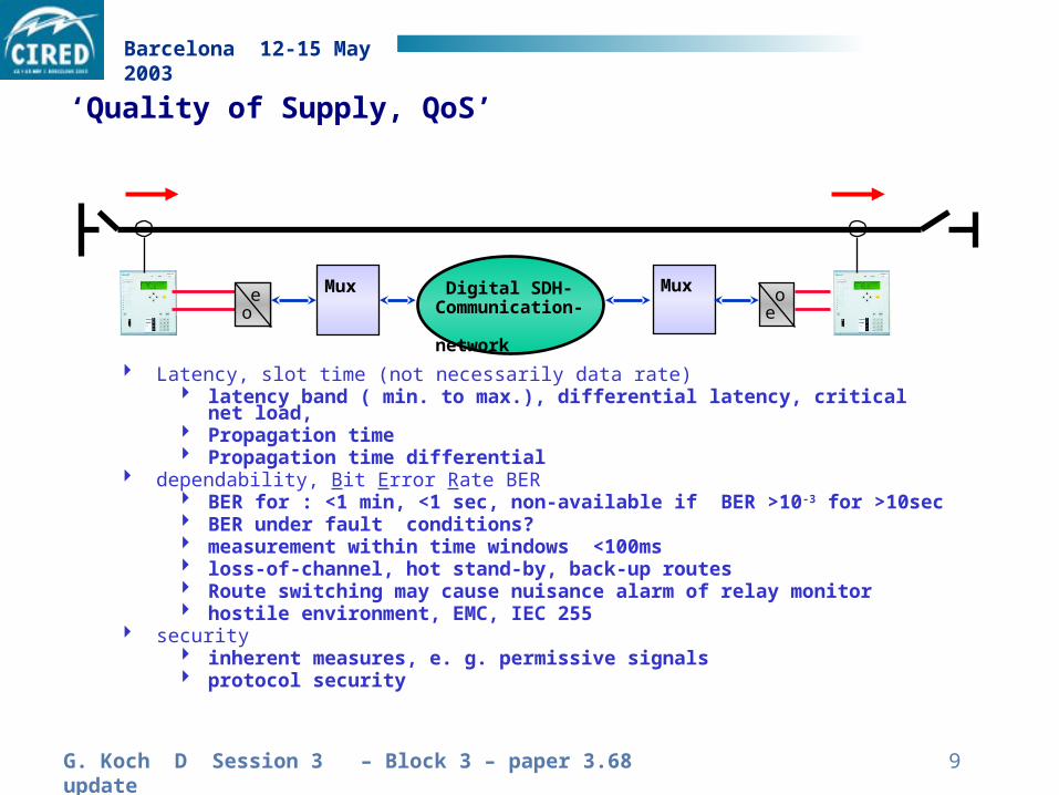
Latency, slot time (not necessarily data rate) latency band ( min. to max.), differential latency, critical net load, Propagation time Propagation time differential
dependability, Bit Error Rate BER BER for : <1 min, <1 sec, non-available if BER >10-3 for >10sec BER under fault conditions? measurement within time windows <100ms loss-of-channel, hot stand-by, back-up routes Route switching may cause nuisance alarm of relay monitor hostile environment, EMC, IEC 255
security inherent measures, e. g. permissive signals protocol security
Digital SDH-Communication- network
eoMuxMux
oe
oe
‘Quality of Supply, QoS’

G. Koch D Session 3 – Block 3 – paper 3.68 update
Barcelona 12-15 May 2003
Induced Voltage along a Pilot Wire Pair
Legend
I earth fault current
0 flux generated by E/F - current
V induced voltage
V2
V1
V
V
I = fault current
V
2V
2
barrier transformer
E = 2f • M •I •L • r1 • r2
G. Koch D Session 3 – Block 3 – paper 3.68 update
Barcelona 12-15 May 2003
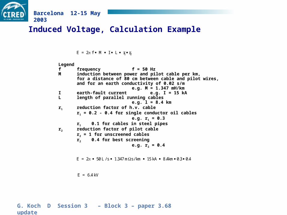
Induced Voltage, Calculation Example
Legendf frequency f = 50 HzM induction between power and pilot cable per km,
for a distance of 80 cm between cable and pilot wires,and for an earth conductivity of 0.02 s/m
e.g. M = 1.347 mH/kmI earth-fault current e.g. I = 15 kAL length of parallel running cables
e.g. l = 8.4 kmr1 reduction factor of h.v. cable
r1 = 0.2 - 0.4 for single conductor oil cablese.g. r1 = 0.3
r1 0.1 for cables in steel pipesr2 reduction factor of pilot cable
r2 = 1 for unscreened cablesr2 0.4 for best screening
e.g. r2 = 0.4
E = 2 f M r1 I L r2
E = 2 50 L / s 1.347 m s / km 15 kA 8.4km 0 3 0 4. .
E = .4 kV6
G. Koch D Session 3 – Block 3 – paper 3.68 update
Barcelona 12-15 May 2003
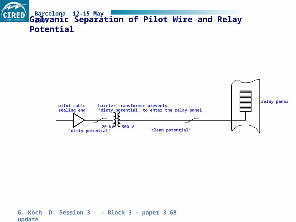
20 kV 500 V
relay panelpilot cablesealing end
barrier transformer prevents'dirty potential' to enter the relay panel
Galvanic Separation of Pilot Wire and Relay Potential
'dirty potential' 'clean potential'