Embed Size (px)
Citation preview
83 | P a g e
Notes on Experiment #12
Phasors and Sinusoidal Analysis
We will do experiment #12 AS IS. Follow the instructions in the experiment as given.
PREPARE FOR THIS EXPERIMENT!
You will take 75 data values during this experiment! That takes time! So, you must come
to the lab prepared! Read about and know about the setup and measuring techniques for
this experiment. If you are not prepared you will not finish this experiment. But, as with
all the other experiment, if you prepare in advance you will finish early.
There is no circuit analysis for this experiment. Prepare the purpose, theory, and
procedure as usual.
You _must_ set up three separate data tables using the headings given in the lab manual.
The first two tables will have the following frequencies (in Hz) down the first column:
100, 200, 400, 600, 800, 1000, 1500, 2000, 2500 and 3000. The frequencies for the third
table will be found experimentally so you cannot list them until you get some data. The
right-most column will have the heading "C" for table 1 and "L" for table 2. Table 3 does
not need that last column.
All of the above preparation must be submitted to your lab instructor at the beginning of
the lab session for scoring and will be returned to you after you set up the first circuit.
The lab report will not be due at the end of the lab session. It will be collected at the
beginning of your next lab session. This is because the data evaluation and plotting will
need more time than we have during the lab session. So, you have an extra week to write
up this report. Given that much time your reports are expected to be perfect! ;)
What You Will Do in Lab
For this experiment you will be solving the mystery of the unknown elements. You will
be given a capacitor and inductor of unknown values. By indirectly measuring the
current-voltage characteristics you will determine the element values. Since the
measuring techniques used are not very accurate (due to visual estimations) we will take
many data samples and get an average value of the data. In the past the average values of
the data have given elements values within 3-5% accuracy!
During the lab session, for each impedance you will measure:
Voltage |VZ|;
84 | P a g e
Voltage |VR|; and
Phase Angle ØZ.
This will be done at each frequency in the tables for each impedance.
What You Will Do at Home
After completing the experiment you will take your data home and:
Fill in the remaining columns of the table;
Calculate the average value of C and L from data of tables 1 and 2 respectively:
Calculate FO_Calc and compare it to FO_Exp (See How it works below);
Plot data:
For each table, plot at each frequency:
o The complex impedance vector in the complex plane; and
o |Z| = F(w) (Connect the points to get an estimated continuous function.)
Write your conclusion.
How it works
We know that the complex impedance is defined by:
|Z| / ØZ = |VZ| / ØV / |IZ| / ØI
The Magnitude of Z
At each frequency in the table you will be directly measuring the RMS magnitude of the
voltage across your elements and indirectly measuring the RMS magnitude of the current
through your elements using the DMM. The ratio of these magnitudes gives the
magnitude of the Complex Impedance of your element. SO,
|Z| = |VZ| / |IZ|
You will use a 100 Ohm resistor in series with Z to indirectly measure the magnitude of
IZ. Since R is in series with Z they have the same current. If we measure |VR| then:
|IZ| = |VR| / R [Be sure you measure R so you know its exact value.]
The Phase Angle of Z
Also at each frequency, you will directly measure the Phase Angle difference between the
sinusoidal voltage and current using the oscilloscope (scaled to degrees using the
technique explained in your lab manual. READ IT! KNOW IT!) This phase angle
difference is the phase angle of the complex impedance of your element since:
85 | P a g e
ØZ = ØV - ØI
On the scope we will position IZ so that ØI = 0. That way ØZ = ØV.
The Sign of the Angle
Lead: If the voltage "leads" the current (voltage has a positive t-axis cross over
point to the left of the positive current t-axis cross over point) then the angle is the
distance in degrees between the two signals and has a positive sign.
Lag: If the voltage "lags" the current (voltage has a positive t-axis cross over
point to the right of the positive current t-axis cross over point) then the angle is
the distance in degrees between the two signals and has a negative sign.
Evaluating Z
Once you have the magnitude and phase angle of Z you have its polar form as a complex
number. Convert this to rectangular form and enter the value in the table. You will have:
Z = a ± Jb
The value of b will be used to determine the value of the unknown element.
Table 1 - The Capacitor
Start with the capacitor. We know that for a capacitor that:
ZC = 0 - J/wC
So from your data:
b = 1/(wC) so,
C = 1/(wb)
Calculate the value of C using the value of “b” at each frequency in table 1. Then get the
average value of the ten values of C. Call it CAVG.
Table 2 - The Inductor
Warning: Handle the inductors with care. The fine inductor wire breaks easily.
The inductor provided to you is made of very long piece (10 yds?) of very fine wire
wrapped around a metal core. This wire will have a resistance RL of about 40 to 80 Ohms
depending on your actual inductor. We cannot remove that resistance. So your actual
"practical" inductor will behave like a resister in series with an ideal inductor so:
ZL_prac = RL + JwL
86 | P a g e
So from your data:
a = RL and
b = wL so,
L = b/w
Calculate the value of L using the value of “b” at each frequency in table 2. Then get the
average value of the ten values of L. Call it LAVG. Note that the average value of data “a”
is the average value of RL.
Please Note: In the drawing of the practical inductor in your lab manual the ideal R is RL
and NOT the 100 Ohm resister in the circuit setup used to find |IZ|.
Table 3 - The Capacitor and Inductor in Series
For the series combination of the capacitor and inductor the total impedance will be:
ZLC = ZC + ZL_prac = 1/JwC + ( RL + JwL). So,
ZLC = RL + J(wL - 1/wC)
Notice that at a particular frequency wo (called the resonant frequency):
woL - 1/(woC) = 0
At wo, ZLC = RL + J0 is a pure Real number. So the phase angle is zero. It is easy to show
that:
wo = 1/[(LC)1/2
]
Define: FO_Calc = 1/{2π[(LAVG *CAVG)1/2
]} as the calculated resonant frequency in Hertz.
You will find the experimental resonant frequency FO_Exp by adjusting the frequency
control dial on the function generator until the voltage and current images on the scope
display cross the t-axis together everywhere. This means the phase angle is zero. Note
that for your L-C combinations FO_Exp will be in the range of 1000 to 6500 Hz. For table
3 use frequencies based on FO_Exp as follows:
FO_Exp - 1000 Hz
FO_Exp - 500 Hz
FO_Exp
FO_Exp + 500 Hz
FO_Exp + 1000 Hz
87 | P a g e
You must fill in table 3. So, you will need the voltage and phase angles for each of the
above calculated frequencies. Don't forget to get that data.
Setup Tips
Run the function gen. amplitude at max output.
Ch 2 must be set negative. (Pull Invert)
The taller the images on the scope the more easily the angles can be measured.
The images do not need to be the same height.
Check that the baseline (line you see in GND mode) for both channels on the
scope are in the same position - dead center on the screen - before each
measurement.
All of the phase angles for the capacitor should be -90 degrees (as it has
negligible internal resistance). The capacitor behaves in an ideal manner. For
some of you the angle may drop a few degrees at frequencies above 1500 Hz. i.e
you may get -87 or -82 but never -91 or higher(in magnitude.)
The phase angle for the practical inductor at 100Hz is NOT zero. It is a very small
angle in the range of about 2 to 12 degrees. Zero degrees will skew your data.
OK. That was a lot. But once you start the experiment it will move quickly since it is so
repetitive in nature.
Have fun.
88 | P a g e
ECE 225 Experiment #12
Phasors and Sinusoidal Analysis
Purpose: Measure phasors and impedance; study a series resonant circuit.
Equipment: Keysight 34461A Digital Multimeter, Keysight DSO-X 2012A Oscilloscope,
Keysight 33500B Waveform Generator, Universal Breadbox Universal
Breadbox
I. Introduction
A phasor is a complex number having a magnitude and a phase angle. The
magnitude of phasor voltages and currents can be measured directly with the
DMM. However the phase angle of a phasor is always taken relative to some
standard; it represents the phase shift of the sinusoidal current or voltage in
question, with respect to some reference sinusoidal current or voltage. In the
circuit below we will take the reference quantity to be the current, and we will
measure the phase shift of various voltages with respect to this current. Actually,
since voltages are more convenient to deal with than currents we will use the
voltage -VR/R, which is equal to i.
89 | P a g e
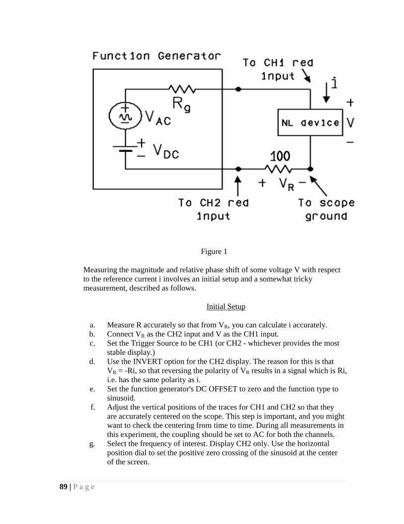
Figure 1
Measuring the magnitude and relative phase shift of some voltage V with respect
to the reference current i involves an initial setup and a somewhat tricky
measurement, described as follows.
Initial Setup
a. Measure R accurately so that from VR, you can calculate i accurately.
b. Connect VR as the CH2 input and V as the CH1 input.
c. Set the Trigger Source to be CH1 (or CH2 - whichever provides the most
stable display.)
d. Use the INVERT option for the CH2 display. The reason for this is that
VR = -Ri, so that reversing the polarity of VR results in a signal which is Ri,
i.e. has the same polarity as i.
e. Set the function generator's DC OFFSET to zero and the function type to
sinusoid.
f. Adjust the vertical positions of the traces for CH1 and CH2 so that they
are accurately centered on the scope. This step is important, and you might
want to check the centering from time to time. During all measurements in
this experiment, the coupling should be set to AC for both the channels.
g. Select the frequency of interest. Display CH2 only. Use the horizontal
position dial to set the positive zero crossing of the sinusoid at the center
of the screen.
90 | P a g e
Measuring the phase angle and magnitude of v
h. Apply v to the CH1 input and VR to CH2. Adjust the controls until you get
a good picture. Make sure that the ground lines of both the traces are at the
center of the screen.
i. Find out the phase difference of V with respect to VR from the horizontal
scale. If the time difference is t, then the phase difference is given by
φ = t*f/360 degrees, where f is the frequency of the signal.
j. Determine the rms value of V which is also called the magnitude of phasor
V. Together with the phase angle from VR, this determines the phasor V.
When the frequency of the sinusoid is changed you might need to change
the horizontal scale for precisely measuring the phase difference.
II. Measuring phasor voltages and impedances
For Z (NL in the Figure), use the capacitor provided by your instructor, and let V
be the voltage VZ across Z. Measure the magnitude and phase angle. Repeat the
measurement at 10 frequencies provided by your instructor.
Present your results in three forms:
1. as a table;
2. as a graph of Z in the complex plane showing the points Z(w) for
10 different values of w, each point labeled with the value of w;
and
3. as a graph of |Z(w)| vs w. Estimate the value of C from the
theoretical |Z(w)| = 1/wC and put it in the table. Expect some
deviation from theoretical since capacitors also involve internal
resistance which is called ESR (Equivalent series resistance).
Calculate the average value of C from the 10 estimates. This value
will be used in a later section.
Next repeat the investigation of the last paragraph, this time using an
inductor provided by your instructor. (In the tabular representation, the last
column will be "L".) Your results will reflect the fact that practical
inductors really consist of a resistor and an inductor in series; the RL is
internal resistance of the wire from which the inductor is wound.
From your investigation, deduce the values of RL and L for each of the 10
trials, and average them. These values will be used later.
91 | P a g e
III. A series resonant circuit
This part investigates the phenomenon of series resonance. The impedance or the
NL device of the circuit consists of the capacitor you measured earlier, in series
with the practical inductor you measured earlier.
Display VR on CH2 and V on CH1 as you have done before. Adjust the frequency
of the signal generator until you find the frequency at which V has a zero phase
angle, i.e. the impedance Z(w) is purely real. This is the observed series resonant
frequency of the circuit. Call it wo. Now calculate the resonant frequency, using
the theoretical formula wo = 1/(LC)1/2
and using the values of L and C which you
determined earlier in part II above. Compare with the observed value.
Investigate the magnitude and phase angle of VZ, with respect to i, at frequencies
in the vicinity of wo. On the scope you should be able to see a very dramatic
change of magnitude and angle of VZ in this vicinity. Observe and record your
results in the same 3 forms explained earlier, but without the last column (C or L)
of the earlier tables. Take sufficient data in the vicinity of the resonant frequency
to allow you to draw a good graph of |Z(w)|; draw the graph as you take the data.
Then on the same axes with your experimentally derived plot of Z(w), draw the
plot which would be expected on a theoretical basis, and comment.
3 | P a g e
General Lab Instructions
The Lab Policy is here just to remind you of your responsibilities.
Lab meets in room 3250 SEL. Be sure to find that room BEFORE your first lab meeting.
You don't want to be late for your first (or any) lab session, do you? Arrive on time for all
lab sessions.
You must attend the lab section in which you are registered. You can not make up a
missed lab session! So, be sure to attend each lab session.
REMEMBER: You must get a score of 60% or greater to pass lab.
It is very important that you prepare in advance for every experiment. The Title page and
the first four parts of your report (Purpose, Theory, Circuit Analysis, and Procedure)
should be written up BEFORE you arrive to your lab session. You should also prepare
data tables and bring graph paper when necessary. To insure that you get into the habit of
doing the above, your lab instructor MAY be collecting your preliminary work at the
beginning of your lab session. Up to four points will be deducted if this work is not
prepared or is prepared poorly. This work will be returned to you while you are setting up
the experiment.
NOTE: No report writing (other than data recording) will be allowed until after you
have completed the experiment. This will insure that you will have enough time to
complete the experiment. If your preliminary work has also been done then you should
easily finish your report before the lab session ends. Lab reports must be submitted by the
end of the lab session. (DEFINE END OF LAB SESSION = XX:50, where XX:50 is the
time your lab session officially ends according to the UIC SCHEDULE OF CLASSES.)
Each student should submit one lab report on the experiment at the end of each lab
session. If your report is not complete then you must submit your incomplete report. If
you prepare in advance you should always have enough time to complete your
experiment and report by the end of the lab session.
1 | P a g e
A semester of Experiments for ECE 225
Contents
General Lab Instructions ................................................................................................................. 3
Notes on Experiment #1 .................................................................................................................. 4
ECE 225 Experiment #1
Introduction to the function generator and the oscilloscope .................................................... 5
Notes on Experiment #2 ................................................................................................................ 14
ECE 225 Experiment #2
Practice in DC and AC measurements using the oscilloscope .................................................. 16
Notes on Experiment #3 ................................................................................................................ 21
ECE 225 Experiment #3
Voltage, current, and resistance measurement ....................................................................... 22
Notes on Experiment #4 ................................................................................................................ 29
ECE 225 Experiment #4
Power, Voltage, Current, and Resistance Measurement .......................................................... 30
Notes on Experiment #5 ................................................................................................................ 32
ECE 225 Experiment #5
Using The Scope To Graph Current-Voltage (i-v) Characteristics ............................................. 33
Notes on Experiment #6 ................................................................................................................ 37
ECE 225 Experiment #6
Analog Meters ........................................................................................................................... 40
Notes on Experiment #7 ................................................................................................................ 42
2 | P a g e
ECE 225 Experiment #7
Kirchoff's current and voltage laws .......................................................................................... 44
Notes on Experiment #8 ............................................................................................................... 56
ECE 225 Experiment #8
Theorems of Linear Networks ................................................................................................... 52
Notes on Experiment #9 ............................................................................................................... 55
ECE 225 Experiment #9
Thevenin's Theorem ................................................................................................................. 57
Notes on Experiment #10 .............................................................................................................. 56
Operational Amplifier Tutorial ...................................................................................................... 63
ECE 225 Experiment #10
Operational Amplifiers .............................................................................................................. 72
Notes on Experiment #11 .............................................................................................................. 78
ECE 225 Experiment #11
RC Circuits ................................................................................................................................. 81
Notes on Experiment #12 .............................................................................................................. 83
ECE 225 Experiment #12
Phasors and Sinusoidal Analysis ............................................................................................... 88


![Phasors Final Ron Alexander.ppt [Read-Only] · While represented as phasors, the impedance and power “phasors” do not rotate at system frequency. The international standard is](https://img.pdfslide.net/doc/110x75/5e187b822001895a3240f732/phasors-final-ron-read-only-while-represented-as-phasors-the-impedance-and-power.jpg)