Embed Size (px)
Citation preview
PHILIPP Connecting rails and loops
Installation Instruction
VB
3-V-
004-
en -
07/1
8
PHILIPP Connecting rails and loops
2 © 2018 PHILIPP GmbH, 63741 Aschaffenburg • Technical changes and errors reserved • July 2018
Transport and mounting systems for prefabricated building
Technical department Our staff will be pleased to support your planning phase with suggestions for the
installation and use of our transport and mounting systems for precast concrete construction.
Special designs Customized to your particular needs.
Practical tests on site We ensure that our concepts are tailored precisely to your requirements.
Inspection reports For documentation purposes and your safety.
On-site service Our engineers will be pleased to instruct your technicians and production per-
sonnel at your plant, to advise on the installation of precast concrete parts and to assist you in the optimisation of your production processes.
High safety level when using our products Closecooperationwithfederalmaterialstestinginstitutes(MTIs),andofficialap-
provals for the use of our products and solutions whenever necessary.
Software solutions The latest design software, animated videos and CAD libraries can always be
found under www.philipp-gruppe.de.
Engineering contact Phone: +49 (0) 6021 / 40 27-318
Fax: +49 (0) 6021 / 40 27-340 E-mail: [email protected]
Sales contact Phone: +49 (0) 6021 / 40 27-300
Fax: +49 (0) 6021 / 40 27-340 E-mail: [email protected]

3© 2018 PHILIPP GmbH, 63741 Aschaffenburg • Technical changes and errors reserved • July 2018
PHILIPPGROUP
System components ............................................................. Page 4
Application ............................................................................. Page 5
Connecting loops ................................................................. Page 6
Connecting rails .................................................................... Page 8
General ................................................................................. Page 10
Mortar grouting ...................................................................... Page 11
Concrete ................................................................................ Page 11
Grouting mortar ..................................................................... Page 11
Thixotropic mortar ................................................................. Page 11
ContentContent
PHILIPP Connecting rails and loops
4 © 2018 PHILIPP GmbH, 63741 Aschaffenburg • Technical changes and errors reserved • July 2018
The Connecting loop resp. the Connecting rail is used for constructive connections of prefabricated concrete parts under predominantly static loads. In combination with a suitable mortar they can transfer loads, which do not require a special approval (no high forces).
AllPHILIPPconnectionsystemsarehighlyflexibleandcreateareinforcementsplicewhichfunctionsontheprincipleofalapped splice. Herewith, it is possible to realise even complicate connections in an easy way.
Both, the Connecting loop and rail can be used without any proof in concrete elements which do not have any load-bearing function. The easy handling guarantees a simple installation.
Advantages of the Connecting loop and rail
Flexible connecting components with small areas of grouting No need to bend back any reinforcement Less weight than a similar rebend connection with stiff reinforcement bars Simple design, as existing reinforcement need not to be changed Simpleinstallationduetoflexiblewireropeendsandpre-cutnail-holes Anchoring also possible in thin connection walls Version for lightweight concrete with appropriate anchoring available Weather-proof cover can be removed easily No mix-up due to colour codes and directional marking
System components
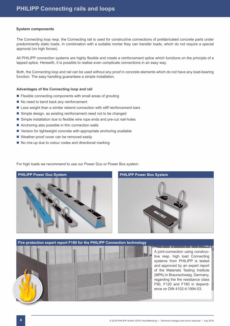
For high loads we recommend to use our Power Duo or Power Box system.
PHILIPP Power Duo System PHILIPP Power Box System
Fire protection expert report F180 for the PHILIPP Connection technology
A joint-connection using construc-tive resp. high load Connecting systems from PHILIPP is tested and approved by an expert report of the Materials Testing Institute (MPA) in Braunschweig, Germany, regardingthefireresistanceclassF90, F120 and F180 in depend-ence on DIN 4102-4:1994-03.
5© 2018 PHILIPP GmbH, 63741 Aschaffenburg • Technical changes and errors reserved • July 2018
PHILIPPGROUP
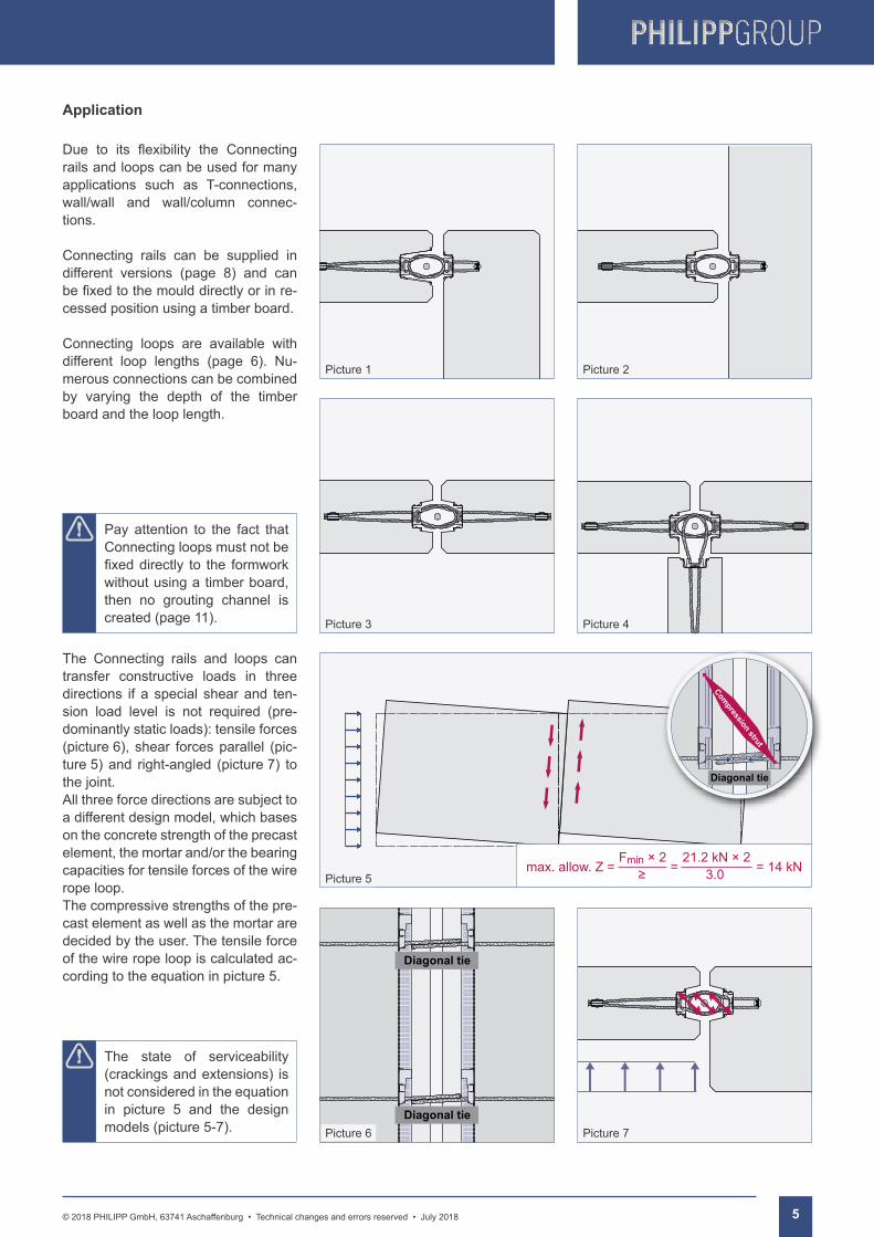
Due to its flexibility the Connectingrails and loops can be used for many applications such as T-connections, wall/wall and wall/column connec-tions.
Connecting rails can be supplied in different versions (page 8) and can befixedtothemoulddirectlyorinre-cessed position using a timber board.
Connecting loops are available with different loop lengths (page 6). Nu-merous connections can be combined by varying the depth of the timber board and the loop length.
The Connecting rails and loops can transfer constructive loads in three directions if a special shear and ten-sion load level is not required (pre-dominantly static loads): tensile forces (picture 6), shear forces parallel (pic-ture 5) and right-angled (picture 7) to the joint.All three force directions are subject to a different design model, which bases on the concrete strength of the precast element, the mortar and/or the bearing capacities for tensile forces of the wire rope loop.The compressive strengths of the pre-cast element as well as the mortar are decided by the user. The tensile force of the wire rope loop is calculated ac-cording to the equation in picture 5.
max. allow. Z = F × 2min
≥=
21.2 kN × 2
3.0= 14 kN
Application
Pay attention to the fact that Connecting loops must not be fixeddirectly to the formworkwithout using a timber board, then no grouting channel is created (page 11).
The state of serviceability (crackings and extensions) is not considered in the equation in picture 5 and the design models (picture 5-7).
Picture 5
Diagonal tie
Diagonal tiePicture 6 Picture 7
Picture 1 Picture 2
Picture 3 Picture 4
Diagonal tie
Compression strut
PHILIPP Connecting rails and loops
6 © 2018 PHILIPP GmbH, 63741 Aschaffenburg • Technical changes and errors reserved • July 2018
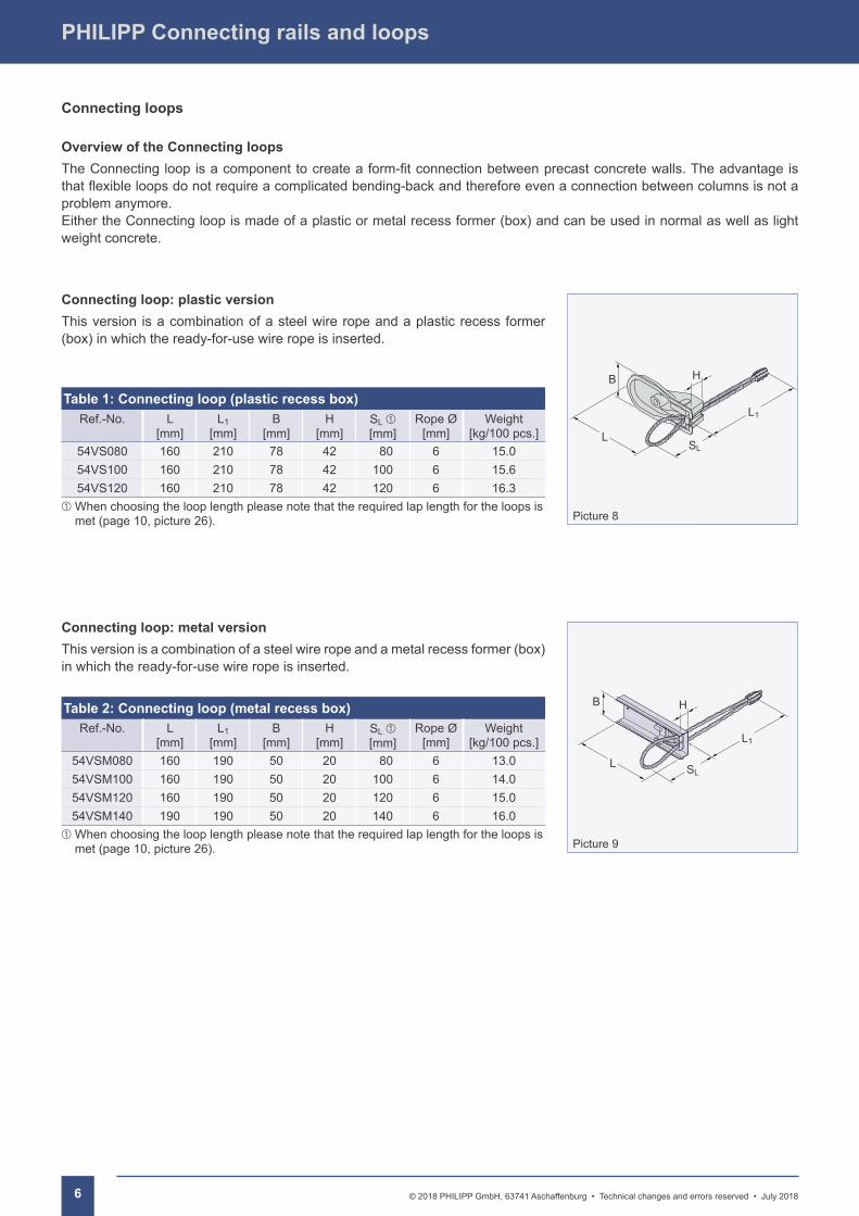
Connecting loop: plastic versionThis version is a combination of a steel wire rope and a plastic recess former (box) in which the ready-for-use wire rope is inserted.
Table 1: Connecting loop (plastic recess box)Ref.-No. L
[mm]L1
[mm]B
[mm]H
[mm]SL [mm]
Rope Ø [mm]
Weight[kg/100 pcs.]
54VS080 160 210 78 42 80 6 15.054VS100 160 210 78 42 100 6 15.654VS120 160 210 78 42 120 6 16.3
When choosing the loop length please note that the required lap length for the loops is met (page 10, picture 26).
Connecting loop: metal versionThis version is a combination of a steel wire rope and a metal recess former (box) in which the ready-for-use wire rope is inserted.
Table 2: Connecting loop (metal recess box)Ref.-No. L
[mm]L1
[mm]B
[mm]H
[mm]SL [mm]
Rope Ø [mm]
Weight[kg/100 pcs.]
54VSM080 160 190 50 20 80 6 13.054VSM100 160 190 50 20 100 6 14.054VSM120 160 190 50 20 120 6 15.054VSM140 190 190 50 20 140 6 16.0
When choosing the loop length please note that the required lap length for the loops is met (page 10, picture 26).
Overview of the Connecting loopsTheConnectingloopisacomponenttocreateaform-fitconnectionbetweenprecastconcretewalls.Theadvantageisthatflexibleloopsdonotrequireacomplicatedbending-backandthereforeevenaconnectionbetweencolumnsisnotaproblem anymore. Either the Connecting loop is made of a plastic or metal recess former (box) and can be used in normal as well as light weight concrete.
Connecting loops
Picture 8
L
B
SL
L1
H
Picture 9
L
B
SL
L1
H
7© 2018 PHILIPP GmbH, 63741 Aschaffenburg • Technical changes and errors reserved • July 2018
PHILIPPGROUP
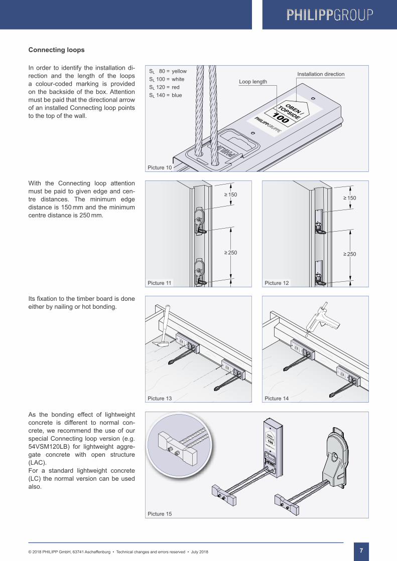
As the bonding effect of lightweight concrete is different to normal con-crete, we recommend the use of our special Connecting loop version (e.g. 54VSM120LB) for lightweight aggre-gate concrete with open structure (LAC).For a standard lightweight concrete (LC) the normal version can be used also.
In order to identify the installation di-rection and the length of the loops a colour-coded marking is provided on the backside of the box. Attention must be paid that the directional arrow of an installed Connecting loop points to the top of the wall.
Itsfixationtothetimberboardisdoneeither by nailing or hot bonding.
With the Connecting loop attention must be paid to given edge and cen-tre distances. The minimum edge distance is 150 mm and the minimum centre distance is 250 mm.
100
OB
EN
/T
OP
SID
E
100
OB
EN
/T
OP
SID
E
100
OB
EN
/T
OP
SID
E
100
OB
EN
/T
OP
SID
E
100
OB
EN
/T
OP
SID
E
100
OB
EN
/T
OP
SID
E
100
OB
EN
/T
OP
SID
E
100
OB
EN
/T
OP
SID
E
100
OBEN /
TOPSIDE
100
OBEN /TOPSIDE
100
OBEN /TOPSIDE
Connecting loops
Picture 13 Picture 14
Picture 10
Installation directionLoop length
Picture 11 Picture 12
Picture 15
SL 80 = yellowSL 100 = whiteSL 120 = redSL 140 = blue
≥150
≥250
≥150
≥250
PHILIPP Connecting rails and loops
8 © 2018 PHILIPP GmbH, 63741 Aschaffenburg • Technical changes and errors reserved • July 2018
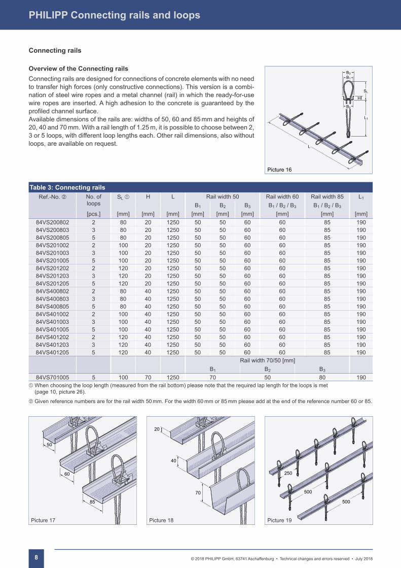
Overview of the Connecting railsConnecting rails are designed for connections of concrete elements with no need to transfer high forces (only constructive connections). This version is a combi-nation of steel wire ropes and a metal channel (rail) in which the ready-for-use wire ropes are inserted. A high adhesion to the concrete is guaranteed by the profiledchannelsurface.Available dimensions of the rails are: widths of 50, 60 and 85 mm and heights of 20, 40 and 70 mm. With a rail length of 1.25 m, it is possible to choose between 2, 3 or 5 loops, with different loop lengths each. Other rail dimensions, also without loops, are available on request.
Table 3: Connecting railsRef.-No. No. of
loopsSL H L Rail width 50 Rail width 60 Rail width 85 L1
B1 B2 B3 B1 / B2 / B3 B1 / B2 / B3
[pcs.] [mm] [mm] [mm] [mm] [mm] [mm] [mm] [mm] [mm]84VS200802 2 80 20 1250 50 50 60 60 85 19084VS200803 3 80 20 1250 50 50 60 60 85 19084VS200805 5 80 20 1250 50 50 60 60 85 19084VS201002 2 100 20 1250 50 50 60 60 85 19084VS201003 3 100 20 1250 50 50 60 60 85 19084VS201005 5 100 20 1250 50 50 60 60 85 19084VS201202 2 120 20 1250 50 50 60 60 85 19084VS201203 3 120 20 1250 50 50 60 60 85 19084VS201205 5 120 20 1250 50 50 60 60 85 19084VS400802 2 80 40 1250 50 50 60 60 85 19084VS400803 3 80 40 1250 50 50 60 60 85 19084VS400805 5 80 40 1250 50 50 60 60 85 19084VS401002 2 100 40 1250 50 50 60 60 85 19084VS401003 3 100 40 1250 50 50 60 60 85 19084VS401005 5 100 40 1250 50 50 60 60 85 19084VS401202 2 120 40 1250 50 50 60 60 85 19084VS401203 3 120 40 1250 50 50 60 60 85 19084VS401205 5 120 40 1250 50 50 60 60 85 190
Rail width 70/50 [mm]B1 B2 B3
84VS701005 5 100 70 1250 70 50 80 190 When choosing the loop length (measured from the rail bottom) please note that the required lap length for the loops is met
(page 10, picture 26).
Given reference numbers are for the rail width 50 mm. For the width 60 mm or 85 mm please add at the end of the reference number 60 or 85.
Connecting rails
L
B2
SL
L1
H
Picture 16
B1
B3
Picture 17
50
60
85
Picture 18
20
40
70
Picture 19
250
500
500
9© 2018 PHILIPP GmbH, 63741 Aschaffenburg • Technical changes and errors reserved • July 2018
PHILIPPGROUP
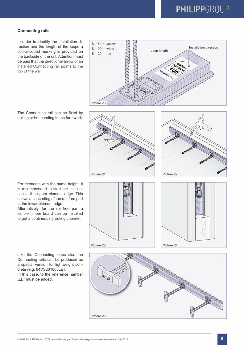
In order to identify the installation di-rection and the length of the loops a colour-coded marking is provided on the backside of the rail. Attention must be paid that the directional arrow of an installed Connecting rail points to the top of the wall.
The Connecting rail can be fixed bynailing or hot bonding to the formwork.
For elements with the same height, it is recommended to start the installa-tion at the upper element edge. This allows a concreting of the rail-free part at the lower element edge.Alternatively, for the rail-free part a simple timber board can be installed to get a continuous grouting channel.
Like the Connecting loops also the Connecting rails can be produced as a special version for lightweight con-crete (e.g. 84VS201005LB). In this case, to the reference number „LBˮmustbeadded.
100
OBEN /
TOPSIDE
Connecting rails
100
OBEN /TOPSIDE
Picture 21 Picture 22
Picture 20
Picture 23 Picture 24
Picture 25
SL 80 = yellowSL 100 = whiteSL 120 = red
Installation directionLoop length
PHILIPP Connecting rails and loops
10 © 2018 PHILIPP GmbH, 63741 Aschaffenburg • Technical changes and errors reserved • July 2018
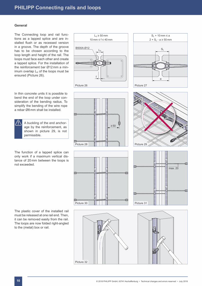
The Connecting loop and rail func-tions as a lapped splice and are in-stalled flush or as recessed versionin a groove. The depth of the groove has to be chosen according to the loop length and height of the rail. The loops must face each other and create a lapped splice. For the installation of the reinforcement bar Ø12 mm a min-imum overlap Lü of the loops must be ensured (Picture 26).
The function of a lapped splice can only work if a maximum vertical dis-tance of 20 mm between the loops is not exceeded.
In thin concrete units it is possible to bend the end of the loop under con-sideration of the bending radius. To simplify the bending of the wire rope a rebar Ø8 mm shall be installed.
The plastic cover of the installed rail must be released at one rail end. Then, it can be removed easily from the rail. The loops are now folded right-angled to the (metal) box or rail.
General
A buckling of the end anchor-age by the reinforcement, as shown in picture 29, is not permissible.
f
B500A Ø12Lü
max. 20
Picture 32
Picture 26 Picture 27
≥50
Picture 30 Picture 31
Picture 28 Picture 29
SL
a
SL+10mm≤a2 × SL-a≥50mm
Lü≥50mm10mm≤f≤40mm
11© 2018 PHILIPP GmbH, 63741 Aschaffenburg • Technical changes and errors reserved • July 2018
PHILIPPGROUP
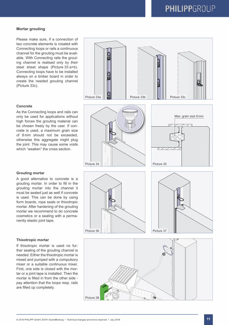
Please make sure, if a connection of two concrete elements is created with Connecting loops or rails a continuous channel for the grouting must be avail-able. With Connecting rails the grout-ing channel is realised only by their steel sheet shape (Picture 33 a+b). Connecting loops have to be installed always on a timber board in order to create the needed grouting channel (Picture 33c).
ConcreteAs the Connecting loops and rails can only be used for applications without high forces the grouting material can be chosen freely by the user. If con-crete is used, a maximum grain size of 8 mm should not be exceeded, otherwise this aggregate might plug the joint. This may cause some voids which “weaken” the cross section.
Grouting mortarA good alternative to concrete is a groutingmortar. In order to fill in thegrouting mortar into the channel it must be sealed just as well if concrete is used. This can be done by using form boards, rope seals or thixotropic mortar. After hardening of the grouting mortar we recommend to do concrete cosmetics or a sealing with a perma-nently elastic joint tape.
Thixotropic mortarIf thixotropic mortar is used no fur-ther sealing of the grouting channel is needed. Either the thixotropic mortar is mixed and pumped with a compulsory mixer or a suitable continuous mixer. First, one side is closed with the mor-tar or a joint tape is installed. Then the mortarisfilledinfromtheotherside-pay attention that the loops resp. rails arefilledupcompletely.
Mortar grouting
Picture 34 Picture 35
Picture 33a
Picture 36 Picture 37
Picture 38
Picture 33b Picture 33c
Max. grain size 8 mm

PHILIPP GmbHLilienthalstrasse 7-9D-63741 AschaffenburgPhone: + 49 (0) 6021 / 40 27-0Fax: + 49 (0) 6021 / 40 [email protected]
PHILIPP GmbHRoßlauer Strasse 70D-06869 Coswig/AnhaltPhone: + 49 (0) 34903 / 6 94-0Fax: + 49 (0) 34903 / 6 [email protected]
PHILIPP GmbHSperberweg 37D-41468 NeussPhone: + 49 (0) 2131 / 3 59 18-0Fax: + 49 (0) 2131 / 3 59 [email protected]
PHILIPP Vertriebs GmbHLeogangerstraße 21A-5760 Saalfelden / SalzburgPhone + 43 (0) 6582 / 7 04 01Fax + 43 (0) 6582 / 7 04 01 [email protected]
For more information visit our website: www.philipp-group.de
Sustainable solutions
PHILIPP ACON Hydraulic GmbHHinter dem grünen Jäger 3D-38836 DardesheimPhone: + 49 (0) 39422 / 95 68-0Fax: + 49 (0) 39422 / 95 [email protected]
Our customers trust us to deliver. We do everything in our power to reward their faith and we start each day intending to do better than the last. We provide strength and stability in an ever-changing world.
Welcome to the PHILIPP Group
PHILIPPGROUP
07/1
8