Embed Size (px)
Citation preview

PHOENIX
Phoenix Panel ACM Submittal Package
PHOENIX

PHOENIX
Flatness
The Architectural Panel’s strength and rigidity allows for the elimination of dimpling, buckling and oil canning. Our state of the art machinery enables us to control quality concerns such as camber and thickness throughout the manufacturing process. Superior flatness and the combined integral rigidity of our panel system allows the surface to remain constant under ever-changing environmental conditions.
Fabrication
• Easy cutting, grooving, punching, drilling and curving.• Panels can be designed to create curves, reverse curves and small radii.• Tight return edges
Paint and Resin Systems
• Superior abrasion characteristics • Solid and metallic finishes• Field paintable• Polyester• Class 1 Anodized• PVDF (Kynar)• Lumiflon®, Polyester, Class 1 Anodized and Kynar 500TM all meet AAMA 2605 • Lumiflon®, a high-performance resin coating that offers: • Rich palette of vivid colors • Broad spectrum of gloss levels • Excellent recoating capacity
Technical Data
Phoenix Rise System

PHOENIX
Retrofit
Phoenix Architectural Panels offer the perfect solution to improve the overall visual enhancement of an existing building. In today’s construction market, additions and/or renovations to an existing building is the economical choice for many owners and developers. Phoenix panel’s smooth and rigid exterior is the cost-effective alternative when renovating a building.
Panel Size
Plank is produced in these standard sizes. Panels can be fabricated within these dimensions.
Width: 32.5”–62” (826-1575mm)Length: 6’–24’ (1829-7315mm)
Test proceduresASTM E283-91 – Air infiltration and exfiltrationASTM E331-00 – Water penetrationASTM E330-97 – Wind-load resistance
Product toleranceSquareness: maximum 0.2” (5mm)Bow: maximum 0.5% in length and/or widthWidth: ± 0.08” (2mm) Length: ± 0.16” (4mm)Thickness: • 3mm ± 0.008” (0.2mm)• 4mm ± 0.008” (0.2mm)• 6mm ± 0.012” (0.3mm)
Technical Data
Phoenix Rise System
Fabrication• Tight return edges• Panels can be fabricated to create curves, reverse curves, and small radius sections• Easy cutting, grooving, punching, and drilling
Fire performance
• ASTM E84 Surface Burning UBC26-3 Corner Test (4mm): Passed• CAN/ULC S-134M (4mm): Passed• UBC 17-2, Potential Heat Release: <6000 BTU/ft2

PHOENIX
Phoenix Material Selection

PHOENIX
1. Product Name
ALPOLICª/fr Composite Fire-RatedMetal Panels
2. Manufacturer
Mitsubishi Plastics Composites America, Inc.401 Volvo Parkway Chesapeake, VA 23320 (800) 422-7270Fax: (757) 436-1896E-mail:[email protected] www.alpolic-northamerica.com
3. Product Description
Basic Use:ALPOLICª/fr Composite Metal Panels are used for cladding of non-residential and residential structures. They are manufactured, fabricated and installed to withstand stress from deflection and thermal movement and to maintain performance criteria stated by the manufacturer.
Composition & Materials ALPOLIC/fr Composite Fire-Rated Metal Panels are composed of 3 or 4 mm thick, mineral filled fire resistive thermoplastic core material that meets performance characteristics specified when fabricated into composite assembly. Face sheets are aluminum3105-H14 alloy, or equivalent, 0.020” (0.51 mm) thick. Sheets are thermally bonded in continuous process to core material.
Finishes
ALPOLIC/fr panels are available with fluorocarbon and polyester coatings. The fluorocarbon finish is a Lumiflonª based resin. Miflon-based fluoropolymer resin coatings meet or exceed values expressed in AAMA 2605 where relevant to coil coatings. Stainless steel and titanium finishes are available.
Materials - AlpolicMetal Wall Panels
Colors
A pallet of bright, vibrant and vivid colors in a wide gloss range is available. A Class 1 anodized finish is available, as well as a stone series finish.
Limitations
Deflection of perimeter framing member should not exceed L/175 normal to plane of the wall; deflection of individual panels should not exceed L/60. At connection points of framing members to anchors, anchor deflection in any direction should not exceed 1/16” (1.6 mm). Allow for free horizontal and vertical thermal movement, due to expansion and contraction of components over a temperature range. Fabrication, assembly and erection procedures should take into account the ambient temperature range at the time of the respective operation. Wall design should feature provisions to drain to the exterior face of the wall any leakage of water at joints and any condensation that can occur within the construction.

PHOENIX
American Architectural Manufacturers Association
(AAMA) - AAMA 2605 Voluntary Specification, Performance Requirementsand Test Procedures for Superior Performing Organic Coatings on Aluminum Extrusions and Panels Underwriters’ Laboratories of Canada, Ltd. (ULC) - CAN/ULC S134M
Approvals
International Building Code (IBC) ResearchReport Number NER 672National Building Code (Canada) City of New York MEA 142-99-E City of Los Angeles RR 25362Miami Dade NOA 06-0531.12/.13
Physical/Chemical Properties Tested for resistance to delamination as follows:
• Bond strength (ASTM C297)- 427 psi (3 MPa)minimum• Peel strength (ASTM D1781)- 22.5 in-lbs/in (100 N-m/m) minimum• No degradation in bond performance after8 hours of submersion in boiling water and after 21 days of immersion in water at 70 degrees F (21 degrees C)• Coefficient of expansion (ASTM D696) - 13× 10-6 in/in/°F• Tensile yield 4 mm (ASTM E8)- 6344 psi (44 MPa)• Tensile strength 4 mm (ASTM E8)- 7126 psi (49 MPa)• Elongation - E8: 4 mm - 5%• Thermal conductance (ASTM C976)- 10.75 Btu/(ft2 × h × °F) (18 W/(m2 × K))• Sound transmission coefficient(ASTM E413) -26
Materials - AlpolicMetal Wall Panels
4. Technical Data
Applicable Standards ASTM International• ASTM C297 Standard Test Method for Tensile Strength on Flat Sandwich Constructions inFlatwise Plane• ASTM C976 Standard Test Method for Thermal Performance of Building Assemblies by Means of a Calibrated Hot Box (Withdrawn2002)• ASTM D696 Standard Test Method for Coefficient of Linear Thermal Expansion of Plastics Between -30°C and 30°C With a Vitreous Silica Dilatometer• ASTM D1781 Standard Test Method forClimbing Drum Peel for Adhesives• ASTM D1929 Standard Test Methodfor Determining Ignition Temperature ofPlastics• ASTM E8 Standard Test Method forTension Testing of Metallic Materials• ASTM E72 Standard Test Methods for Conducting Strength Tests of Panels for Building Construction• ASTM E84 Standard Test Methodfor Surface Burning Characteristics ofBuilding Materials• ASTM E108 (Modified) Standard TestMethods for Fire Tests of Roof Coverings• ASTM E119 Standard Test Methods for Fire Tests of Building Construction and Materials• ASTM E283 Standard Test Method for Determining the Rate of Air Leakage Through Exterior Windows, Curtain Walls, and Doors Under Specified Pressure Differences Acrossthe Specimen• ASTM E330 Standard Test Method for Structural Performance of Exterior Windows, Curtain Walls, and Doors by Uniform Static Air Pressure Difference• ASTM E331 Standard Test Method for Water Penetration of Exterior Windows, Curtain Walls and Doors by Uniform Static Air Pressure Difference• ASTM E413 Standard Classification forRating Sound Insulation

PHOENIX
Fire Performance
• Flamespread (ASTM E84) - 0• Smoke developed (ASTM E84) - 10 (for 4mm FR)• Surface flammability - Pass when tested permodified ASTM E108• Flash point (ASTM D1929) - 811 degrees F(433 degrees C)• Ignition temperature (ASTM D1929) -837 degrees F (447 degrees C)• UBC 26-9 (NFPA 285) Intermediate Scale Multi Story Apparatus Test - Passed (4 and 6 mm)• UBC 26-3 Room Corner Test - Passed (4mm)• ASTM E119 One Hour and Two Hour RatedInstalls - Passed (4 mm)• CAN/ULC S134M Canadian Full Scale Test-Passed (4 mm)
Fire test performance has established approval on Types 1, 2, 3, 4 and 5 construction throughout the United States and Canada.
5. Installation
Preparatory Work Field Measurements Verify actual dimensions and openings by field measurement before fabrication. Show recorded measurements on shop drawings. Coordinate field measurements and fabrication schedule with construction progress to avoid construction delays. Submit shop drawings showing layout, profiles and product components, including anchorage, accessories, finish colors and textures. Include details showing thickness and dimensions of various system parts, fastening and anchoring methods, locations of joints and gaskets, movement. Submit selection and verification samples for finishes, colors and textures. and location and configuration of joints necessary to accommodate thermal
Materials - AlpolicMetal Wall Panels
Delivery & Storage
Deliver materials in manufacturer’s original, unopened, undamaged containers with identification labels intact. Finish of panels is protected by heavy duty removable plastic film during production Panels are packaged for protection against transportation damage. Exercise care in unloading, storing and installing panels to prevent bending, warping, twisting and surface damage. Store materials protected from exposure to harmful weather conditions and at temperature conditions recommended by ALPOLIC. Store panels in well-ventilated space out of direct sunlight. Do not store panels in any enclosed space where ambient temperature can exceed 120 degrees F (49 degrees C). Avoid contact with any other materials that might cause staining, denting or other surface damage.
Methods
Shop fabricate to sizes and joint configurations indicated on the drawings. Where final dimensions cannot be established by field measurement, provide allowance for field adjustment as recommended by the fabricator. Form panel lines, breaks and angles to be sharp and true, with surfaces that are free from warp or buckle. Fabricate with sharply cut edges, with no displacement of aluminum sheet or protrusion of core.
Production Tolerances
• Width - ± (1 mm/m)• Length - ± (1 mm/m)• Thickness - ± 0.008” (0.2 mm) for 4 mm panel• Bow - Maximum 0.5% length or width• Squareness - Maximum 0.2” (5 mm)• Edges of sheets shall be square and trimmed with no displacement of aluminum sheets or protrusion of core material
Install panels plumb, level and true, compliance with manufacturer’s recommendations. Anchor panels securely in place, in accordance with fabricator’s approved shop drawings. Comply with fabricator’s instructions for installation of concealed fasteners and with provisions of specifications for installation of joint sealers with fabricator’s approved shop drawings. Comply with fabricator’s instructions for installation of concealed fasteners and with provisions of specifications for installation of joint sealers.

PHOENIX
Materials - AlpolicMetal Wall Panels
Installation Tolerances
Maximum deviation from horizontal and vertical alignment of installed panels is 0.25” in 20’ (6.4 mm in 6 m), non-cumulative. Complete installation recommendations are available from the manufacturer.
Precautions
Repair panels with minor damage so that repairs are not discernible at a distance of 10’ (3 m). Remove and replace panels damaged beyond repair. Remove protective film immediately after installation of joint sealers and immediately prior to completion of composite metal panel work.
Building Codes
Current data on building code requirements and product compliance can be obtained from ALPOLIC technical support specialists. Installationmust comply with requirements of all applicable local, state and national code jurisdictions.
6. Availability & Cost
Contact manufacturer for information on distribution and local availability.
Cost
Budget installed cost information can be obtained from the manufacturer.
7. Warranty
Contact manufacturer for information on warranty conditions, exclusions, duration and remedies.
8. Maintenance
These panels, when properly installed,require no specific maintenance. An occasional pressure washing can be required depending on local environmental conditions. Periodic inspection for sealant integrity is advised to ensure long-term system performance.
9. Technical Services
A staff of trained personnel offers design assistance and technicals support. For technical assistance, contact ALPOLIC, Mitsubishi Plastics Composites America, Inc.
10. Filing Systems
• Reed First Source• MANU-SPECª• Additional product information isavailable from the manufacturer upon request.

PHOENIX
Alpolic Painted ACM Fr Core
Alpolic
Leed Nc 2.2 Contribution -Data Sheet
The Following Has Been Developed To Provide The Information Needed By The Leed Project Team For The Determination Of The Contribution Of The Alpolic Fr Panels Towards Specific Leed Nc Points. In The Event Further Information Is Required Contact Alpolic At 1-800-422-7270 Ext1.
Materials and Resources
MR Credit 4.1: One point is awarded if the materials selected for the project have a recycle content of 10% based on total value. The recycle content is determined as the sum of the post consumer recycle content plus one half of the pre consumer recycle content. For material assemblies, such as cladding systems, the recycled content value shall be determined by weight.
MR Credit 4.2: One point is awarded if the materials selected for the project have a recycle content of 20%. The recycle content is determined using the same methodas noted for Credit 4.1
% weight of panel
% Post Consumer Recycle Content
% Pre Con-sumer Recy-cle Content
Total =100% PostConsumer+ 50% Pre Con-sumer Recycle Content
4 mm ACM frAluminum Skins
35.4 12.5 64.2 44.6
fr Core 64.6 0 0 04 mm Panel 100 4.4 22.7 15.76
6 mm ACM frAluminum Skins
24.8 12.5 64.2 44.6
fr Core 75.2 0 0 06 mm Panel 100 3.1 15.9 11.1
Note: The total recycle content of the panels should be combined with the other components of the cladding system to determine the contribution of the wall cladding to the overall project point qualification

PHOENIX
MR Credit 5.1: 1 point. Regional Materials 10% MR Credit 5.2: 1 point. Regional Materials 20%
The ALPOLIC fr painted ACM panels are produced from several different ma-terials such as aluminum coil, polyethylene, coatings, and protective film. Due to the nature of these materials, specifically their high recycle content it is not possible to identify and quantify the initial extraction location or all of the subse-quent processing points. For this reason it is recommended that ALPOLIC fr not be included in the calculations for this credit.
Indoor Environmental Quality
EO Credit 4.2: 1 point. The intent of this credit is to reduce the harmful or irritat-ing indoor air contaminants that the building occupants or installers are exposed to. All coatings applied to the ALPOLIC fr ACM panels are factory applied using a coating line with an in-line regenerative thermal oxidizer, which eliminates the release of the VOC content of the coating. By factory applying the coatings the need for field paintingand the accompanying VOCs are eliminated.
Innovation in Design
ID Credit 1.1 to 1.4: 4 points are available in this section for exceptional per-formance in meeting the requirements in other sections of the LEED NC rating system or for an innovative performance on green building categories which are not addressed in other sections of the rating system.
The high recycle content of the ALPOLIC fr panels can support the projects ex-ceeding the recycle content required in MR Credit 4.2, thereby qualifying for an Innovation in Design credit. The ALPOLIC panels also provide a highly durableand long life time cladding option.
"USGBC" and related logo is a trademark owned by the U.S. Green Building Council and is used by permission. Mitsubishi Chemical FP America, Inc. is a member of the U.S. Green Building Council and actively supports environmental responsibility.

PHOENIX
To whom the warranties should be made out (Company or Job)
Materials - Apolic
ALPOLIC Warranty Request Form
Complete physical location of job (Include project name, complete address of where panels are installed :street, city, state, zip/postal code)
Project Architect/Owner Phone:
Address:
Email Address:
Please send completed form to Laura J LevineFax- 757-436-1896Email: [email protected]

PHOENIX
24
Property Units RB120PE-3 mm
RB160PE-4 mm
RB240PE-6 mm
RB- 160FR-4
mm
Solid Alumi- num(1)
Thickness Inches mm 0.118 3.0
0.157 4.0
0.236 6.0
0.157 4.0
0.197 5.0
Weight lb/ft2
Kg/m2 0.94 4.59
1.12 5.47
1.49 7.28
1.53 7.48
2.78 13.57
Bon
d I
nte
rgir
ty Min.
Bond Strength
ASTD 1781
in-lb/in Nm/m
40 178
40 178
40 178 22.5 100
— —
Flatwise Shear ASTM D1002
lb/in2
MPa 1,297 8.94
1,221 8.42
2,055 14.7
92.8 6.4
— —
Allowable Bending Stress
lb/in2 MPa
11,500 79.3 11,500 79.3 11,500 79.3 11,500 79.3
11,500 79.3
Coefficient of Expansion ASTM E228
in/in/°F mm/mm/°C
1.31x10⁻⁵
2.36x10⁻⁵ 1.31x10⁻⁵
2.36x10⁻⁵ 1.31x10⁻⁵
2.36x10⁻⁵ 1.31x10⁻⁵
2.36x10⁻⁵ 1.31x10⁻⁵
2.36x10⁻⁵
Stiffness (El) lb in2/in MPa cm4/m
807 9.1x10³ 1,140 12.8x10³
1,896 21.4x10³
1,262 14.3x10³
6,434 74.1x10³
Flexural Mod- ulus Aged per
ASTM C393
lb/in2
MPa 8.3x10⁶
57.2x10³ 6.0x10⁶ 41.4x10³
4.0x10⁶
27.6x10³ 6.7x10⁶ 46.2x10³
10x106 68.9x10³
Moment of Inertia
in4/in cm4/m
0.97x10⁻⁴ 0.159 1.89x10⁻⁴
0.310 4.58x10⁻⁴
0.751 1.89x10⁻⁴
0.310 6.37x10⁻⁴
1.042 Section Modu-
lus in3/in cm3/m
1.65x10⁻³ 1.065 2.41x10⁻³
1.555 3.88x10⁻³
2.503 2.41x10⁻³
1.555 6.47x10⁻³
4.167 Tensile Yield ASTM D638
lb/in2
MPa 8,300 57.23 6,405 44.16 5,314
36.64 6,367 43.90
19,000 130.0
Flatwise Tensile ASTM
C297
lb/in2
MPa 1,483 10.22 1,371
9.45 1,099 7.58
961 6.62
— —
“R” Thermal Resistance (core only)
Ft2hr°F BTU
m2K w
0.034 6.0x10⁻³ 0.051 9.0x10- 3
0.086 15.1x10⁻³
0.026 —
— —
STC Sound Transmission
Coefficient ASTM E90
— —
— —
26 — —
— —
— —
Maximum Width
Inches mm
62 1,575
62 1, 575
62 1, 575
62 1,575 — —
Maximum Length
Inches mm
243 6,172
243 6,172
243 6,172
243 6,172 — —
1 Solid aluminum properties are based on Alloy 3105-H25. Information contained herein or related hereto is intended only for evaluation by technically skilled persons, with any use thereof to be at their independent discretion and risk. Such information
is believed to be reliable, but Alcoa Architectural Products (“Alcoa”) shall have no responsibility or liability for results obtained or damages resulting from such use. Alcoa grants no license under, and shall have no responsibility or liability for infringement of,
any patent or other proprietary right. Nothing in this document should be construed as a warranty or guarantee by Alcoa, and the only applicable warranties will be those set forth in Alcoa acknowledgment or in any printed warranty documents issued by Alcoa. The foregoing may be waived or modified only in writing by an Alcoa officer. For a complete technical overview of all Reynobond
products, visit www.alcoaarchitecturalproducts.com.
Materials -REYNOBOND
Engineering Properties U.S and Metric Equivalent
Typical Engineering Properties Composite-designed Reynobond® panels consist of a thermoplastic compound core faced with two sheets of aluminum. There are two varieties, a Polyethylene (PE) core and a Fire Resistant (FR) core.

PHOENIX
25
Materials -REYNOBOND
EVOLUTION TECHNICAL DATA SHEETS PREMIUM FIXING SOLUTIONS
Description: Ruspert® metal finish is a non-organic, high grade metal surface processing technology that prevents corrosion. It consists of three layers: the first layer; a metallic zinc layer, the second; a high grade anticorrosion chemical conversion film, and a third outer layer; baked ceramic surface coating. The distinguishing feature of Ruspert® is the tight joining of the baked ceramic surface coating and the chemical conversion film. These layers are bonded together through chemical reactions, and this unique method of combining layers results in a rigid combination of the coating films. Ruspert® treatment does not attribute its anti-corrosion properties to merely a single material, but the synergy of these three layers, which combined have superb rustproof qualities. Compatible with metal coated and painted surfaces, fasteners coated with Ruspert® are resistant to acid and alkaline attack, galvanic corrosion and hydrogen embrittlement. These fasteners conform to corrosive gas test standard (Kesternich) DIN50018 SFW-0.25 and give a Salt Spray Fog Test to exceed (JISZ2731) 504 Hours.
Features: • Superior corrosion resistance. Excellent against gas, weathering and other kinds of corrosive factors including Salt Water. • Resistant to Acid and Alkaline Attack, Galvanic Corrosion and Hydrogen Embrittlement. • Corrosion resistance against scratches. Composite layers minimize the effect of scratches on
the protection coating. • Electrolytic corrosion resistance. Less contact corrosion with other metals. • Low process temperature. The drying temperature below 200ºC protects the products from metallo graphic changes.
• A variety of colors. Various colors to suit different purposes. • Paintable.
Ruspert® Coating Color Samples (from Evolution Products):
Silver/ Grey Ruspert Blue Ruspert Green Ruspert * All tests reported on this data sheet were carried out by the Nihon Ruspert Co. Ltd
UNIT 5, BLOCK 16, CLYDESMILL ROAD, CLYDESMILL INDUSTRIAL ESTATE,
GLASGOW, G32 8RE. TEL: 0141 646 0055. FAX: 0141 646 0033
EMAIL: [email protected]. WEBSITE: www.evolutionfasteners.co.uk

PHOENIX

PHOENIX
Typical Vertical Joint
Phoenix Rise System

PHOENIX
Typical Horizontal Joint
Phoenix Rise System

PHOENIX
Flashed Parapet
Phoenix Rise System

PHOENIX
Flashed Parapet
Phoenix Rise System

PHOENIX
Window Head
Phoenix Rise System

PHOENIX
Window Sill
Phoenix Rise System

PHOENIX
Window Jamb
Phoenix Rise System

PHOENIX
Window Head
Phoenix Rise System

PHOENIX
Window Sill
Phoenix Rise System

PHOENIX
Window Jamb
Phoenix Rise System
PHOENIX
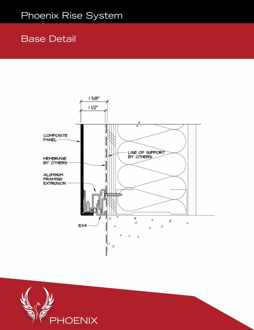
Base Detail
Phoenix Rise System

PHOENIX
End Wall Detail
Phoenix Rise System

PHOENIX
Inside Corner
Phoenix Rise System

PHOENIX
Soffit Detail
Phoenix Rise System

PHOENIX
Rectangular Column Cover
Phoenix Rise System
PHOENIX
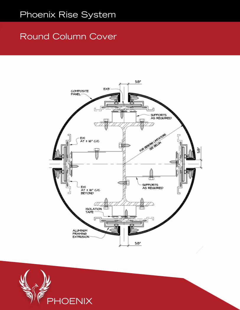
Round Column Cover
Phoenix Rise System


![[ACM-ICPC] 0 - ACM-ICPC](https://img.pdfslide.net/doc/110x75/555603ead8b42a3f168b4838/acm-icpc-0-acm-icpc.jpg)

