Embed Size (px)
Citation preview

S
Pd
Xa
b
a
ARRAA
KCHOPPS
1
risesip(ttep
amto[
0h
Materials Science and Engineering B 181 (2014) 86– 92
Contents lists available at ScienceDirect
Materials Science and Engineering B
jou rn al h om epa ge: www.elsev ier .com/ locate /mseb
hort communication
hotocatalytic hydrogen generation with simultaneous organicegradation by a visible light-driven CdS/ZnS film catalyst
i Wanga,b, Xiao-yan Lib,∗
School of Chemistry and Environment, South China Normal University, Guangzhou, Guangdong, ChinaEnvironmental Engineering Research Centre, Department of Civil Engineering, The University of Hong Kong, Pokfulam Road, Hong Kong
r t i c l e i n f o
rticle history:eceived 29 June 2013eceived in revised form 23 October 2013ccepted 18 November 2013vailable online 2 December 2013
eywords:dS–ZnS
a b s t r a c t
A layered CdS/ZnS catalyst film was synthesized on glass using the stepped chemical bath depositionmethod. The film catalyst was shown as visible light-driven photocatalyst capable of producing H2 undervisible light. The ZnS outer layer helped suppress the recombination of photo-generated electron–holepairs on the CdS base layer, leading to faster H2 generation. The use of the ZnS layer also greatly improvedthe stability of the catalyst film and prevented the leaching of Cd2+ from the CdS layer. Deposition of Ru onthe catalyst film further increased its photoreactivity for H2 production. The photocatalyst was effective inH2 production together with the degradation of model organic substances, such as formic acid, methanol,
ydrogen generationrganic degradationhotolysishotocatalyst filmolar energy
and ethanol. The greatest H2 production rates were achieved using the CdS/ZnS/Ru film in the formic acidsolution at 123 �mol/m2-h under visible light and 135 mmol/m2-h under the simulated solar light. Thecorresponding theoretical reduction rates of chemical oxygen demand (COD) were 1.9 and 2.1 g/m2-h,respectively. As the multilayer CdS/ZnS/Ru film catalyst can be easily separated from water, it has a greatpotential for simultaneous photocatalytic hydrogen generation and organic wastewater treatment usingsolar energy.
. Introduction
Hydrogen is one of the most promising forms of clean andenewable energy. Photocatalytic hydrogen generation from waters an attractive and environmentally friendly method to harvestolar energy [1,2]. However, while visible light (� > 420 nm) cov-rs a larger portion of the solar spectrum, most photocatalysts,uch as TiO2, function only under energy-intensive ultraviolet (UV)rradiation. Efforts have been made in recent years to develophotocatalysts, such as metal oxides (e.g. ZnO) and metal sulfidese.g. CdS), that respond to both UV and visible lights for water pho-olysis [3]. However, most photocatalysts are still hampered byypical problems such as the recombination of photo-generatedlectron–hole pairs [4] and low stability of the catalysts due tohoto-corrosion [5–7].
In addition to hydrogen evolution (H+ reduction), photocat-lytic reactions in water possess a strong oxidation power thatay be utilized for pollutant degradation [8,9]. During the pho-
ocatalytic process under solar light, pollutants such as sulfide andrganic matters [3,10], including alcohols [11–15] and organic acids6,15,16], can function as electron donors for hydrogen evolution,
∗ Corresponding author. Tel.: +852 2859 2659; fax: +852 2859 5337.E-mail address: [email protected] (X.-y. Li).
921-5107/$ – see front matter © 2013 Elsevier B.V. All rights reserved.ttp://dx.doi.org/10.1016/j.mseb.2013.11.015
© 2013 Elsevier B.V. All rights reserved.
while the pollutants are degraded. In such a photocatalytic appli-cation, the purposes of both hydrogen generation and wastewatertreatment using solar energy can be achieved [6,9].
Most visible light-driven photocatalysts are produced andapplied in a powder form. However, for potential application inwastewater treatment, an easy separation of the photocatalystsfrom the treated effluent is required. Hence, there are efforts madeto immobilize photocatalysts in solid carriers to eliminate theneed for separation in the treatment process [17–20]. However,few studies have been conducted on the use of film-type cata-lysts for photocatalytic hydrogen production together with organicpollutant degradation [21–23]. In our previous study, compositeCdS/ZnS nanoparticles were synthesized as a visible light-drivenphotocatalyst for H2 production [24]. The present work aims todevelop a multilayer film-type CdS/ZnS catalyst that can achieveboth photocatalytic H2 production and organic degradation underthe simulated solar light or visible light.
2. Materials and methods
2.1. Preparation of the CdS/ZnS thin film catalysts
Microscopic glass slides were used as the base material for thedeposition of the CdS/ZnS catalyst films. The catalyst was depositedon both sides of a slide with a dimension of 2.5 cm × 5.5 cm. The
ce and
gwsdiC(uwp3as
csssfibtCcTb
bsb25aataid
2
gsf(ft(fmiFwW
2p
dllvwlt
X. Wang, X.-y. Li / Materials Scien
lass slides were cleaned thoroughly with detergent, degreasedith ethanol in an ultrasonic cleaner, and then etched in 4% HNO3
olution. The chemical bath deposition (CBD) process was used toeposit the catalyst material on the glass surface. The CdS coat-
ng solution was prepared using an aqueous solution of 0.005 Md(NO3)2 in a 0.005 M NH4NO3 buffer mixed with 0.06 M thioureaSC(NH2)2). The pH of the coating solution was adjusted to 8.5–9.5sing 25% NH4OH. During the deposition process, the glass slidesere immersed in the coating solution in a beaker, which was thenlaced in a water bath heated to 50 ◦C. The CBD process lasted for0 min to allow CdS deposition. The CdS film on the glass was thennnealed at 450 ◦C for 1 h in a furnace (LHT 02/16 LBR, Nabertherm)upplied with pure nitrogen.
The outer ZnS layer was coated following the same CBD pro-edures. The ZnS coating solution was prepared in an aqueousolution of 0.04 M Zn(NO3)2 with was chelated with 0.04 × 2/3 tri-odium citrate (Na3C6H5O7) mixed with 0.06 M thiourea, and theolution pH was adjusted to 10 [25]. The glass slides with the CdSlm were immersed in the solution for ZnS deposition in a waterath at 50 ◦C for different CBD periods (1, 2, and 3 h). Accordingly,he catalyst films were denoted as CdS/ZnS-1 h, CdS/ZnS-2 h, anddS/ZnS-3 h for the different ZnS coating periods. The glass slidesoated with the catalyst film were then annealed at 450 ◦C for 1 h.he amount of CdS/ZnS coated on the slide surface was calculatedy the weight increase after the catalyst coating.
Ruthenium (Ru) was deposited on the surface of the catalyst filmy in situ photodeposition in a 10% (vol) acetic acid (CH3COOH)olution of RuCl3 (Aldrich). The photodeposition was conductedy illuminating (� > 420 nm, 300 W Xe lamp) the CdS/ZnS film for0 min in 150 mL of the coating solution with a Ru concentration of3.5 mg/L. For CdS/ZnS-2 h, the catalyst layer on the slide weighedbout 800 mg. According to the concentration measurement, nearlyll Ru3+ in the solution (8.025 mg) deposited on the slide afterhe photodeposition. Thus, the resulting Ru deposition density waspproximately 1.0 wt% (i.e. ∼8 mg vs. ∼800 mg) of the catalyst coat-ng layer of CdS/ZnS-2 h. The catalyst film with Ru deposition wasenoted as CdS/ZnS/Ru.
.2. Characterization of the film photocatalysts
The amount (mass) of the film catalyst that was coated on alass slide was determined from the weight increase after eachtep of the chemical deposition. The crystalline phase and structuraleatures of the catalysts were analyzed using an X-ray diffractionXRD) system (D8 Advance, Bruker AXS) with Cu K� irradiationrom 10 to 90 degrees. The diffuse reflection spectrum (DRS) ofhe catalyst film was obtained using a UV–vis spectrophotometerLambda 25, Perkin Elmer) that was converted from the reflectionunction to the absorbance function following the Kubelka–Munk
ethod [26]. The morphology of the thin catalyst film was exam-ned under a scanning electron microscope (SEM, Hitachi S-4800EG), and the thickness of the catalyst film on the glass surfaceas measured using an atomic force microscope (AFM, BioMATTM
orkstation).
.3. Photocatalytic H2 production with different model organicollutants under visible light
The photocatalytic hydrogen production experiments were con-ucted in a cylindrical photo cell made of optical glass. A 300 W Xe
amp setup (PLS-SXE Xe light source, Trustech) was used as theight source with a cutoff filter (� < 420 nm) installed to provide
isible light (denoted by Vis, light intensity ∼70 mW/cm2) andithout a cutoff filter to simulate the solar light (denoted by Solar,ight intensity ∼86 mW/cm2). Two pieces of the glass slides withhe catalyst film were placed next to each other in the photo cell
Engineering B 181 (2014) 86– 92 87
filled with 150 mL of water or an organic solution. The light wasapplied from the top of the photo cell on a total catalyst filmarea of 27.5 cm2. Different model organic pollutants (formic acid,methanol, and ethanol) were tested for the photocatalytic H2 pro-duction and organic degradation experiments. The solution had anorganic content of 10% by volume and was kept at pH ∼ 7. The gasproduced during the photo-tests was collected, and its hydrogenand carbon dioxide contents were determined using a gas chro-matograph (HP5890 Series II, Hewlett Packard). Each run of thephoto-test lasted approximately 4 h. The reactivity of the photo-catalyst in different solutions was evaluated in terms of the specifichydrogen production rate (R) and energy conversion efficiency (�),as determined by the following equations:
RA = mH2
At, (1)
or
Rw = mH2
Wt, (2)
and
� = R�HC
I, (3)
where RA and Rw are the area-based and weight-based specific H2production rates, respectively, mH2 is the moles of the H2 produced,t the duration of the photoreaction, A the irradiation area (27.5cm2), W the amount (weight) of the catalyst in the photocell forH2 generation, �Hc the combustion value of H2 (286 kJ/mol), andI is the light density. The photocatalytic H2 generation test wasrepeated 10 times for each catalyst film under an experimentalcondition to evaluate the reproducibility of the experiment andthe stability of the film catalyst. In addition, the amount of Cd2+
leaching into the water during the photocatalytic experiments wasmeasured using an atomic absorption spectrometer (AAnalyst 300,Perkin Elmer).
3. Results and discussion
3.1. Synthesis and optimization of the double-layer film catalysts
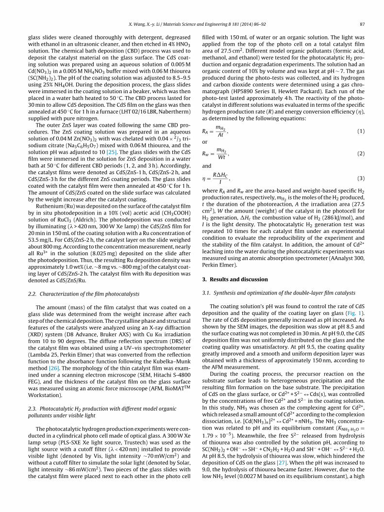
The coating solution’s pH was found to control the rate of CdSdeposition and the quality of the coating layer on glass (Fig. 1).The rate of CdS deposition generally increased as pH increased. Asshown by the SEM images, the deposition was slow at pH 8.5 andthe surface coating was not completed in 30 min. At pH 9.0, the CdSdeposition film was not uniformly distributed on the glass and thecoating quality was unsatisfactory. At pH 9.5, the coating qualitygreatly improved and a smooth and uniform deposition layer wasobtained with a thickness of approximately 150 nm, according tothe AFM measurement.
During the coating process, the precursor reaction on thesubstrate surface leads to heterogeneous precipitation and theresulting film formation on the base substrate. The precipitationof CdS on the glass surface, or Cd2+ + S2− ↔ Cds(s), was controlledby the concentrations of free Cd2+ and S2− in the coating solution.In this study, NH3 was chosen as the complexing agent for Cd2+,which released a small amount of Cd2+ according to the complexiondissociation, i.e. [Cd(NH3)n]2+ ↔ Cd2+ + nNH3. The NH3 concentra-tion was related to pH and its equilibrium constant (KNH3·H2O =1.79 × 10⁻⁵). Meanwhile, the free S2− released from hydrolysisof thiourea was also controlled by the solution pH, according toSC(NH2)2 + OH− ↔ SH− + CN2H2 + H2O and SH− + OH− ↔ S2− + H2O.
At pH 8.5, the hydrolysis of thiourea was slow, which hindered thedeposition of CdS on the glass [27]. When the pH was increased to9.0, the hydrolysis of thiourea became faster. However, due to thelow NH3 level (0.0027 M based on its equilibrium constant), a high
88 X. Wang, X.-y. Li / Materials Science and Engineering B 181 (2014) 86– 92
H = 8.
ctbopwCtdci
ptCpoffidi
tfs
ZnS layer under the visible light and simulated solar light (Fig. 2).Deposition of ZnS on the CdS layer did not reduce its H2 productionactivity. On the contrary, the ZnS outer layer significantly increasedthe H2 production rate of the photocatalyst film. With the ZnS
0
20
40
60
80
100
120
140
160
180
200
0 1 2 3 4
Hyd
roge
n pr
oduc
tion
(µm
ol)
ZnS- 2h (UV+ Vis) Zn S-2h (Vis)
CdS/ZnS-3hr (UV+Vis) CdS/ ZnS-3h (Vis)
CdS/ZnS-2h (UV+Vis) CdS/ ZnS-2h (Vis)
CdS/ZnS-1hr (UV+Vis) CdS/ZnS-1h (Vis)
CdS (UV+Vis) CdS (Vis)
Fig. 1. SEM micrographs of the CdS catalyst film deposited at (A) p
oncentration of free Cd2+ resulted in a rapid CdS precipitation onhe glass surface and in the bulk solution. This facilitated a cluster-y-cluster deposition to form a thick and non-uniform coating layern the glass surface. The coating layer was loose and could easilyeel from the surface. At pH 9.5, a smooth and uniform CdS filmas formed on the glass with adequate NH3 (0.0088 M) chelatingd2+ and sufficient hydrolysis of thiourea. The film growth rate andhickness were moderate, for which the heterogeneous ‘ion by ion’eposition was expected at the surface with a low potential of filmracking [28]. Thus, pH 9.5 was chosen for the deposition of thenner CdS layer.
The ZnS layer was deposited by the similar chelating system atH 10 to form a condensed film [25]. The ZnS growth rate was con-rolled by the deposition temperature. The morphology of ZnS anddS layers and their interface was examined by SEM (Fig. S3, Sup-orting Material). At a low temperature of 40 ◦C, the ZnS depositedn the CdS surface was thin, uneven and loose, which could easilyall off from the surface. At a high temperature of 60 ◦C, the ZnSlm was thick and the interface was loose. At 50 ◦C, the best filmeposition quality could be achieved with a compact ZnS layer and
ts firm adhesion to the inner CdS layer.
The outer ZnS layer was found to affect the photo-reactivity ofhe CdS/ZnS film catalyst. For photocatalytic H2 production withormic acid as the model organic, hydrogen was produced by theingle layer CdS film, and no hydrogen was produced by the single
5, (B) pH = 9.0, and (C) pH = 9.5 (left: cross-section; right: surface).
Time (h)
Fig. 2. Photocatalytic H2 production under visible light or simulated solar light bythe catalyst films with different amounts of ZnS deposition (ZnS-1h, ZnS-2h, andZnS-3h specify the duration (1, 2, and 3 h) of ZnS deposition on the catalyst films).

X. Wang, X.-y. Li / Materials Science and Engineering B 181 (2014) 86– 92 89
Fs
ctaoio
3p
gwTcctc(aipv
fisZ
20 30 40 50 60 70 80 90
Inte
nsity
(a.u
.)
2θ (degree)
▫
▫ ▫▫▪ ▪ ▪
▪▫ CdS ZnS
▫ ▫▫▫
Single layer CdS
Dua l layer CdS/Zn S
photoelectrical mechanisms have been identified for quantum-dotsensitized solar cells [29,30]. Under solar light, the excited elec-tron of ZnS outer layer injected in to the CB of CdS increased the
0
0.1
0.2
0.3
0.4
0.5
0.6
0.7
0.8
390 440 490 540 590
Abso
rban
ce (a
rb. U
nit)
Single-layer CdS
Doub le-l ayer Cd S/ZnS
Single-layer ZnS
ig. 3. SEM images of the double-layer CdS/ZnS thin film on glass (top: cross-ection; bottom, surface).
oating for 2 h, the double-layer film catalyst CdS/ZnS-2 h achievedhe highest H2 production rate of 31.2 �mol/h under visible lightnd 45.9 �mol/h under the solar light, which is three times of thatbtained with the single-layer CdS film. However, further increas-ng the ZnS coating period to 3 h resulted in no additional increasef the H2 production rate.
.2. Characterization of the double-layer CdS/ZnS thin filmhotocatalyst
The inner CdS and outer ZnS layers can be well identified on thelass slides (Fig. 3). The base CdS formed a dense layer on the glassith an average thickness of about 150 nm as measured by the AFM.
he outer layer of CdS/ZnS-2 h had an average thickness of 125 nmonsisting of fine ZnS particles. The XRD analysis indicated differentrystal phases of the CdS/ZnS film catalyst (Fig. 4). For instance,hree XRD peaks at scattering angles (2�) of 26.5◦, 43.8◦, and 52.0◦
ould be indexed to the diffractions of the cubic CdS crystal latticeJCPDS Card No. 75-1546), of which the peaks at 26.5◦ and 52.0◦
re associated with only the cubic phase. The XRD peak at 36.5◦
s associated with only the hexagonal CdS phase. ZnS crystallinehase appears at 2� = 28.7◦, 48.4◦, and 56.4◦, which are close to thealues reported for cubic ZnS (JCPDS card No. 5-0566).
The diffuse reflection spectra of the single-layer CdS and ZnSlms and the double-layer CdS/ZnS film displayed the photo-ensitivity of the catalyst films (Fig. 5). As expected, single-layernS did not responded to visible light. CdS responded well to
Fig. 4. XRD patterns of the CdS and the CdS/ZnS catalyst films (CdS, black square;ZnS, open square).
visible light with a narrow band-gap of 2.23 eV determined fromthe absorbance edge in Fig. 5. For the double-layer CdS/ZnS film,its absorbance increased greatly in the low wavelength range ofvisible light in comparison to the single ZnS layer. The ZnS coatingon the CdS film also resulted in a slight blue shift of the absorbanceedge compared to the single-layer CdS film. The double-layerCdS/ZnS film had a band-gap of 2.45 eV, suggesting a similarresponse as the CdS film to visible light.
While CdS responses to visible light, ZnS adsorbs only UV irra-diation. However, when ZnS was deposited on CdS to form acomposite CdS/ZnS thin film, the reactivity of the photocatalystincreased clearly as suggested by the photo-test results. There isan apparent synergistic effect between the two catalyst materialsfor the photocatalytic process. The use of the more photoreactiveCdS layer ensured the reactivity and efficiency of the catalyst filmunder visible light [24]. Moreover, the sensitive CdS would func-tion as a photo-sensitizer to induce the excitation of ZnS that wasin direct contact with CdS. The higher conduction band and lowervalence band of ZnS demonstrate the heterojunction of ZnS/CdS. Inthis case, this heterojunction can establish fast transport channelsalong with efficient separation and effectively suppress the electronloss at the CdS surface. As shown in Fig. S1 (Supplementary Mate-rial), the electron flow through the heterojunction between CdS andZnS is important to the effective electron–hole separation. Similar
Wavelength (n m)
Fig. 5. Diffuse reflection spectra of the double-layer CdS/ZnS film and the single-layer CdS and ZnS films.

90 X. Wang, X.-y. Li / Materials Science and Engineering B 181 (2014) 86– 92
0
200
400
600
800
0
10
20
30
40
50
1 2 3 4 5 6 7 8 9 10
Cd2
+ re
leas
ing
rate
(μg/
h)
Hyd
roge
n pr
oduc
tion
rate
(μm
ol/h
)
Photo-test cycle
Cd release Cd release
H2 production H2 production
CdS/ZnS: CdS:A-Visibl e light
0
200
400
600
800
0
10
20
30
40
50
1 2 3 4 5 6 7 8 9 10
Cd2+
rele
asin
g ra
te (μ
g/h)
Hyd
roge
n pr
oduc
tion
rate
(μm
ol/h
)
Phot o-test cycle
Cd rele ase Cd rele aseH2 Production H2 Production
CdS-ZnS: CdS:
B-Solar light
Fig. 6. Comparisons between the double-layer CdS/ZnS catalyst film and the single-lat
ett[
tlduoot
ca2ClcssCl
it
ayer CdS film in terms of H2 production, the stability of the photocatalytic reactivity,nd the rate of Cd2+ release under (A) visible light and (B) simulated solar light (eachest lasted 4 h).
lectron flow to the surface and helped suppress the recombina-ion of electron–hole pairs formed in the CdS inner layer, makinghe electrons more available for H2 evolution as show in Fig. S114,15].
The use of the outer ZnS layer also improved the stability ofhe CdS-based photocatalyst under either the visible light or simu-ated solar light. After 10 runs of the photo-H2 tests, the compositeouble-layer catalyst retained 90% of its H2-producing capabilitynder visible light, while the single-layer CdS film retained only 52%f its reactivity for H2 production (Fig. 6A). A similar comparisonf the test results was also observed under the solar light betweenhe photocatalyst films with and without the ZnS layer (Fig. 6B).
The ZnS outer layer also prevented the leaching of Cd2+ from theatalyst film during the photocatalytic process. Between test runs 2nd 5, the CdS/ZnS-2 h catalyst had an average Cd2+ leaching rate of4.7 �g/h under visible light, while the single-layer CdS film had ad2+ leaching rate of 73.7 �g/h (Fig. 6A). Between runs 6 and 10, the
eaching of Cd2+ from CdS/ZnS-2 h diminished to a rate of 1.2 �g/hompared to the CdS film with a Cd2+ leaching rate of 24.3 �g/h. Theimilar results were obtained with the same catalyst films underolar light (Fig. 6B). Use of the outer ZnS layer physically separateddS from the reaction medium to protect the more reactive CdS
ayer against photo-corrosion.The adhesion and stability of the coating films are of extremely
mportance to the performance of the film catalyst. The quality ofhe catalyst films was regularly assessed by manual examination
Fig. 7. (A) Photocatalytic H2 production and (B) the corresponding COD removalrate by the CdS/ZnS and CdS/ZnS/Ru catalyst films in different organic solutions.
and visual and SEM observations during the synthesis process andthe photocatalytic hydrogen production tests. After a number oftest runs, the aqueous solution remained clean and clear, and theSEM images also showed the compact morphology of the films (Fig.S2, Supporting Material). There was no sign of the films peeling offfrom the slide surface. The thickness and roughness of the filmsbefore and after the hydrogen production tests were also detectedby the AFM, and the results presented in Table S1 (Supporting Mate-rial) show little changes of the photocatalyst films (the thicknessremained at ∼150 nm with a roughness of ∼13 nm). As reported inFig. 6, after 10 runs of the photo-H2 tests, the composite catalystfilm retained 90% of its H2-producing capability under visible light.All of these indicate the good quality and stability of the catalystfilms deposited on the glass slides.
3.3. Hydrogen production with simultaneous organic degradation
The CdS/ZnS film catalyst was capable of both photocatalytic H2production and organic degradation under visible light and solarlight (Fig. 7A). The H2 production rate increased for the modelorganic pollutants in an order of ethanol, methanol, and formicacid. For the photocatalyst films in pure water, no hydrogen wasproduced in the absence of the model organics even under thesolar light. The photocatalyst was apparently unable to split waterto produce hydrogen under visible light or solar light. However,
the presence of organic matters enabled the photocatalyst to pro-duce hydrogen from water. The model organic pollutants functionas electron donors for the reduction of H+ ions, giving rise to H2evolution.
ce and
ilaetstehH
aeraHdb
C
wtfi(Cpawrcatr
st[1vSUdertfiwe
C
C
sgootacblc
[
[
X. Wang, X.-y. Li / Materials Scien
Moreover, the Ru deposition on the catalyst surface resultedn a 10-fold increase in H2 production rate. As Ru possesses aower Fermi energy level than CdS/ZnS [31], it would function asn electron collector at the surface of the CdS/ZnS film for thelectrochemical process. The photo-excited electrons could readilyransfer from the photocatalyst to the Ru sites on the catalysturface. Such an electron collection would facilitate the electronransfer from CdS/ZnS to H+ ions in the aqueous solution for H2volution. In other words, Ru deposition on the CdS/ZnS surfaceelps the charge separation on the catalyst, resulting in improved2 generation [32].
The highest H2 production rate under visible light was achievedt 123 mmol/m2-h with the CdS/ZnS/Ru film in formic acid, with annergy conversion efficiency of 1.41%. The highest H2 productionate under the simulated solar light was 135 mmol/m2-h in formiccid, with an energy conversion efficiency of 1.26%. In relation to+ reduction for H2 production, the corresponding organic degra-ation in terms of the chemical oxygen demand (COD) removal maye estimated using the following formula:
OD removal = mH2 MO2
2(4)
here MO2 is the molar mass of O2 (32 g/mol). The theoretical pho-ocatalytic COD reduction rates for formic acid by the CdS/ZnS/Rulm were 5.4 mg/h in visible light and 6.0 mg/h in solar lightFig. 7B), corresponding to area-based-specific rates of 1.9 and 2.1 gOD/m2-h, respectively. Degradation of formic acid resulted in CO2roduction. During the photocatalytic test, CO2 was generated at
rate of 73 mmol/m2-h in the gaseous phase, which agrees wellith the theoretical COD reduction rate of formic acid. The molar
atio of H2 to CO2 produced was approximately 1:1, suggesting aomplete decomposition of formic acid. It is believed that formiccid (E0
CO2/HCOOH = −0.126 V) functioned as an electron donor torap photo-generated holes on the valence band of CdS/ZnS [33],esulting in the organic decomposition and CO2 production.
The hydrogen production rates in the methanol and ethanololutions under visible light were 104 and 92 mmol/m2-h, respec-ively, which are higher than that reported by Daskalaki et al.34] for the Pt/CdS/TiO2 film catalyst. Hydrogen production from0% ethanol achieved an energy conversion efficiency of 1.04% inisible light, which is also higher than the efficiency reported bytrataki et al. [35] for the Pt/TiO2 film catalyst in 80% ethanol underV irradiation. Nonetheless, CO2 production was not detecteduring the photocatalytic H2 generation in both methanol andthanol solutions. It is apparent that the photocatalytic reactionsesulted in organic destruction and intermediate formation otherhan complete organic mineralization [14,36]. When the CdS/ZnSlm catalyst was excited in visible light, the photo-generated holesould attack methanol and ethanol to produce methanal and
thanal, respectively, according to the following reactions [14,37]:
H3OH + h+ → HCHO + H+
H3CH2OH + h+ → CH3CHO + H+
The composite CdS/ZnS double-layer film structure exhibited aynergetic function of the catalyst materials for photocatalytic H2eneration and organic degradation. Moreover, as described previ-usly, film-type photocatalysts can be easily separated from waterr solutions for repeated use. This property is particularly impor-ant in wastewater treatment applications. The catalyst film alsollows better light penetration compared with the suspension of
atalyst powders [38]. The CdS/ZnS/Ru film catalyst had a weight-ased-specific H2 production rate of up to 8.5 mmol/g-h for visibleight irradiation, which was higher than that of the CdS/ZnS/Ruatalyst powders. This implies that the photocatalyst film is as
[[
[[
Engineering B 181 (2014) 86– 92 91
good as catalyst powders in utilizing visible light or solar light forH2 production. Together with its immobilized feature, the multi-layer CdS/ZnS/Ru film catalyst demonstrates a great more potentialfor simultaneous photocatalytic H2 production and wastewaterorganic degradation.
4. Conclusions
• The double-layer CdS/ZnS film catalyst was synthesized by chem-ical bath deposition for photocatalytic H2 production undervisible light. The ZnS outer layer helps suppress the recom-bination of photo-generated electron–hole pairs on the morephotosensitive CdS base layer, leading to a faster H2 productionrate. Moreover, compared with the single-layer CdS film, the useof ZnS in the double-layer CdS/ZnS film greatly improved the sta-bility of the catalyst and prevented the leaching of Cd2+ from thecatalyst film.
• The visible light-driven photocatalyst was capable of both pro-ducing hydrogen and degrading model organic pollutants (formicacid, methanol, and ethanol). The CdS/ZnS/Ru film had an H2 pro-duction rate of 123 mmol/m2-h in the formic acid solution withan energy conversion efficiency of 1.41%. In relation to H2 pro-duction, the theoretical COD reduction rate for formic acid was1.9 g COD/m2-h by the catalyst film under visible light.
• As the multilayer CdS/ZnS/Ru catalyst film is well immobilizedand can be easily separated from water, it presents a great poten-tial in both photocatalytic H2 generation and organic wastewatertreatment using solar energy.
Acknowledgments
This research was supported by grants HKU714112E from theResearch Grants Council (RGC) and SEG HKU10 from the UniversityGrants Committee (UGC) of the Government of Hong Kong SAR, and#51308230 from the National Natural Science Foundation of China(NSFC). The technical assistance of Mr. Keith C.H. Wong is highlyappreciated.
Appendix A. Supplementary data
Supplementary data associated with this article can befound, in the online version, at http://dx.doi.org/10.1016/j.mseb.2013.11.015.
References
[1] K. Maeda, K. Teramura, D.L. Lu, T. Takata, N. Saito, Y. Inoue, K. Domen, Nature440 (2006) 295.
[2] C. Grimes, O.K. Varghese, S. Ranjan, Light, Water, Hydrogen: The Solar Genera-tion of Hydrogen by Water Photoelectrolysis, Springer, New York, USA, 2008.
[3] P. Lianos, J. Hazard. Mater. 185 (2011) 575–590.[4] M.T. Lee, M. Werhahn, D.J. Hwang, N. Hotz, R. Greif, D. Poulikakos, C.P. Grig-
oropoulos, Int. J. Hydrogen Energy 35 (2010) 118–126.[5] M. Law, L.E. Greene, A. Radenovic, T. Kuykendall, J. Liphardt, P.D. Yang, J. Phys.
Chem. B 110 (2006) 22652–22663.[6] X. Zong, H.J. Yan, G.P. Wu, G.J. Ma, F.Y. Wen, L. Wang, C. Li, J. Am. Chem. Soc.
130 (2008) 7176–7177.[7] H. Yan, J. Yang, G. Ma, G. Wu, X. Zong, Z. Lei, J. Shi, C. Li, J. Catal. 266 (2009)
165–168.[8] A. Patsoura, D.I. Kondarides, X.E. Verykios, Catal. Today 124 (2007) 94–102.[9] Y.J. Zhang, L. Zhang, Appl. Surf. Sci. 255 (2009) 4863–4866.10] H. Park, A. Bak, Y.Y. Ahn, J. Choi, M.R. Hoffmannn, J. Hazard. Mater. 211 (2012)
47–54.11] N.L. Wu, M.S. Lee, Z.J. Pon, J.Z. Hsu, J. Photochem. Photobiol. B: Chem. 163 (2004)
277–280.
12] M. Zalas, M. Laniecki, Sol. Energy Mater. Sol. Cells 89 (2005) 287–296.13] S.M. Ji, P.H. Borse, H.G. Kim, D.W. Hwang, J.S. Jang, S.W. Bae, J.S. Lee, Phys. Chem.Chem. Phys. 7 (2005) 1315–1321.14] J.P. Best, D.E. Dunstan, Int. J. Hydrogen Energy 34 (2009) 7562–7578.15] Y.W. Cao, U. Banin, J. Am. Chem. Soc. 122 (2000) 9692–9702.

9 ce and
[
[
[[
[
[
[[
[[
[
[[[[
[[[
[
[
2 X. Wang, X.-y. Li / Materials Scien
16] X.J. Zheng, L.F. Wei, Z.H. Zhang, Q.J. Jiang, Y.J. Wei, B. Xie, M.B. Wei, Int. J.Hydrogen Energy 34 (2009) 9033–9041.
17] C. Guillard, B. Beaugiraud, C. Dutriez, J.M. Herrmann, H. Jaffrezic, N. Jaffrezic-Renault, M. Lacroix, Appl. Catal. B: Environ. 39 (2002) 331–342.
18] S. Zhou, A.K. Ray, Ind. Eng. Chem. Res. 42 (2003) 6020–6033.19] G. Balasubramanian, D.D. Dionysiou, M.T. Suidan, I. Baudin, J.M. Laîné, Appl.
Catal. B: Environ. 47 (2004) 73–84.20] K.L. Rosas-Barrera, J.A. Pedraza-Avella, B.P. Ballén-Gaitán, J. Cortés-Pena, J.E.
Pedraza-Rosas, D.A. Laverde-Catano, Mater. Sci. Eng. B 176 (2011) 1359–1363.21] D.G. Diso, G.E.A. Muftah, V. Patel, I.M. Dharmadasa, J. Electrochem. Soc. 157
(2010) H647–H651.22] N. Strataki, P. Lianos, J. Adv. Oxid. Technol. 11 (2008) 111–115.23] S. Chun, K.S. Han, J.S. Lee, H.J. Lim, H. Lee, D. Kim, Curr. Appl. Phys. 10 (2010)
S196–S200.24] X. Wang, K. Shih, X.Y. Li, Water Sci. Technol. 61 (2010) 2303–2308.25] A. Cheng, D.B. Fan, H. Wang, B.W. Liu, Y.C. Zhang, H. Yan, Semicond. Sci. Technol.
18 (2003) 676–679.26] P. Kubelka, F. Munk, Zeitschrift Technische Physik 12 (1931) 593–601.
[
[[
Engineering B 181 (2014) 86– 92
27] Q. Liu, G.B. Mao, Surf. Rev. Lett. 16 (2009) 469–474.28] T. Ye, Z. Suo, A.G. Evans, Int. J. Solids Struct. 29 (1992) 2639–2648.29] G. Hodes, J. Phys. Chem. C 112 (2008) 17778–17787.30] S.W. Jung, J.-H. Kim, H. Kim, C.-J. Choi, K.-S. Ahn, Curr. Appl. Phys. 12 (2012)
1459–1464.31] A. Kudo, M. Sekizawa, Chem. Commun. 137 (2000) 1–137, 2.32] R. Dholam, N. Patel, A. Miotello, Int. J. Hydrogen Energy 36 (2011) 6519–6528.33] T. Chen, G. Wu, Z. Feng, G. Hu, W. Su, P. Ying, C. Li, Chin. J. Catal. 29 (2008)
105–107.34] V.M. Daskalaki, M. Antoniadou, G.L. Puma, D.I. Kondarides, P. Lianos, Environ.
Sci. Technol. 44 (2010) 7200–7205.35] N. Strataki, V. Bekiari, D.I. Kondarides, P. Lianos, Appl. Catal. B: Environ. 77
(2007) 184–189.
36] Y. Lin, R.F. Lin, F. Yin, X.R. Xiao, M. Wu, W.Z. Gu, W.Z. Li, J. Photochem. Photobiol.B: Chem. 125 (1999) 135–138.37] G.L. Chiarello, L. Forni, E. Selli, Catal. Today 144 (2009) 69–74.38] M. Fathinia, A.R. Khataee, M. Zarei, S. Aber, J. Mol. Catal. A: Chem. 333 (2010)
73–84.