Embed Size (px)
Citation preview
Photocatalytic Layer-by-Layer Coatings for Degradation of AcutelyToxic Agents
Kevin C. Krogman, Nicole S. Zacharia, Doris M. Grillo, and Paula T. Hammond*
Department of Chemical Engineering, Massachusetts Institute of Technology, 77 Massachusetts AVenue,Cambridge, Massachusetts 02139
ReceiVed October 29, 2007. ReVised Manuscript ReceiVed December 6, 2007
Highly reactive layer-by-layer (LbL) films have been developed as protective coatings intended forapplication on fibers worn by military personnel. In this work, the anionic species are titanium dioxidenanoparticles ranging from 5 to 10 nm in size, which are prepared in a stable colloidal solution specificallydesigned for this application, while the cationic species can be one of several traditional syntheticpolycations, including weak and strong polyelectrolytes. The resulting coatings are mechanically stableand offer selective protection when the wearer is exposed to UV radiation (e.g.,sunlight); whereas theinherent water transmissive nature of the multilayers allows for much greater water vapor transport ratesas compared to an inert rubber barrier material. Permeation tests of coated materials were conducted ina specially engineered cell by exposing the materials to a CWA simulant. In the extreme case, when acoated material is subjected to a saturated vapor of the CWA simulant, UV exposure resulted in a 95%decrease in toxic agent permeation. Furthermore, the coating can be deposited via a spray-LbL techniquedeveloped specifically for rapid, uniform deposition over large areas of textile materials at ambienttemperatures and moderate pressures.
Introduction
Increasing concern over the use of chemical warfare,combined with more frequent potential exposure to toxicchemical environments faced by soldiers and emergency careproviders, has heightened the need for new protectivemeasures. Although traditional protective gear for toxiccleanup or exposure has relied on thick layers of dense rubberand/or activated charcoal liners, which act primarily asdiffusive barriers to resist mass transfer, this strategy is nottenable for routine daily duty. Reactive coatings, which areable to selectively degrade toxic chemicals, including chemi-cal warfare agents (CWAs) and environmental toxins suchas NOx and SOx, whereas still affording the wearer a highdegree of water vapor permeability and thus greater comfort,are an interesting strategy for protection against low tomoderate level exposure. Such coatings could also providea route to self-cleaning or decontaminating surfaces or fabricsfor military or commercial use.
One means of eliminating airborne toxins that has receivedattention involves the photocatalytic degradation of toxicorganic compounds using titanium dioxide1–4 to generate
superoxide anions, or mixed TiO2/SiO2 catalysts5–7 toincrease the material’s bandgap and aid in volatile compoundadsorption. Although these strategies exhibit excellent deg-radative capabilities, the technique of depositing unboundpowders or nanoparticles on a surface does not form asufficiently robust coating for application on personal protec-tive equipment. Titania has also been introduced directly intofibers via electrospinning,8 or into bulk films via traditionalsol–gel routes.9 Unfortunately, as the size of the titania entityincreases, it becomes more difficult to introduce the particlesinto a mechanically stable polymer film. The work reportedhere presents a strategy to achieve the success demonstratedby prior titania based systems from an ultrathin, transmissive,and mechanically stable coating that can be readily depositedon traditional military clothing and packaging, as well as avariety of other substrates including electrospun materials.Such a coating can be tuned for its mechanical and chemicalproperties via the choice of polyamine and the incorporationof other polyelectrolytes so as to achieve the reactiveprotection described above, while existing in a form that isdurable enough to withstand the rigors of daily activity andsufficiently discrete so as not to hinder the performance ofthe underlying material. We have developed a coating thatcan be readily deposited by the versatile layer-by-layer (LbL)deposition method10 and provides a reactive barrier of morethan 99% efficiency against a saturated environment of the
* Corresponding author. E-mail: [email protected]. Phone: (617) 258-7577.Fax: (617) 258-5766.
(1) Thompson, T. L.; Panayotov, D. A.; Yates, J. T.; Martyanov, I.;Klabunde, K. J. Phys. Chem. B 2004, 108, 17857.
(2) Martyanov, I.; Klabunde, K. EnViron. Sci. Technol. 2003, 37, 3448.(3) Vorontsov, A. V.; Lion, C.; Savinov, E.; Smirniotis, P. j. Catalysis
2003, 220, 414.(4) Kleinhammes, A.; Wagner, G. W.; Kulkarni, H.; Jia, Y.; Zhang, Q.;
Qin, L.; Wue, Y. Chem. Phys. Lett. 2005, 411, 81.(5) Rodrigues, S.; Uma, S.; Martyanov, I.; Klabunde, K. Abstracts of the
39th Midwest Regional Meeting of the American Chemical Society,Manhattan, KS, Oct 20–22, 2004; American Chemical Society:Washington, D.C., 2004.
(6) Panayotov, D.; Kondratyuk, P.; Yates, J. T. Langmuir 2004, 20, 3674.(7) Martyanov, I. N.; Klabunde, K. J. J. Catal. 2004, 225, 408.(8) Madhugiri, S.; Sun, B.; Smirniotis, P.; Ferraris, J.; Balkus, K.
Microporous Mesoporous Mater. 2004, 69, 77.(9) Yusuf, M.; Imai, H.; Hirashima, H. J. Sol-Gel Sci. Technol. 2002,
25, 65.(10) Decher, G. Science 1997, 277, 1232.
1924 Chem. Mater. 2008, 20, 1924–1930
10.1021/cm703096w CCC: $40.75 2008 American Chemical SocietyPublished on Web 02/07/2008

sulfur mustard simulant compound chloroethyl ethyl sulfide(CEES) when exposed to ultraviolet radiation. Althoughsimilar recent approaches have been taken to introduce titaniananosheets into photocatalytic LbL films,11–13 the resultingcoatings were shown to degrade organic hydrocarbons atrelatively low quantities over time scales on the order ofdays; personal protective equipment, on the other hand, musthave degradative properties on the time scale of minutes, atmost, to be of any practical use. Furthermore, there is generalconcern that titania containing coatings suffer decreasedchemical stability on exposure to UV. However, we havefound the systems reported here to remain intact even afterhigh-yield conversions of simulant agent.
The process of LbL film deposition involves the sequentialexposure of a charged substrate to an alternating series ofsolutions of oppositely charged species. Upon exposure toeach solution the effective charge exhibited by the surfaceis reversed, through adsorption of charged species, beforeproceeding to the next solution. The cycle can be repeatedany desired number of times to develop a highly uniformcoating of precisely controllable thickness on the substrate.This method typically employs polyelectrolytes adsorbedfrom dilute aqueous solutions; however, charged colloidalspecies can also be incorporated into the films.14,15 In someinstances, charged rigid nanoparticles can take the place ofone16 or even both17 of the charged polyelectrolytes. It is inthis manner that we have been able to incorporate reactivetitanium dioxide nanoparticles of very small diameter, andtherefore large reactive surface area, into a mechanicallycohesive film coating. In our approach an automated sprayingmethod is used,18–20 allowing us to rapidly coat a variety ofcomplex substrate geometries and materials including, butnot limited to, cotton textile and protective plastic film.
Experimental Section
LbL Solutions. Poly(dimethyldiallylammonium chloride) (PDAC,MW ) 100 000), and sodium chloride were purchased from Aldrichand used to make a solution of 20 mM concentration with respectto the repeat unit of PDAC, and 10 mM with respect to NaCl, inDI water. Colloidal titania nanoparticles were synthesized by slowlycombining a solution of 1 part tetrabutyl ammonium hydroxide and50 parts absolute ethanol with a solution of 1 part titanium (IV)isopropoxide and 6 parts absolute ethanol by volume as shown inScheme 1. The combined solution was then slowly diluted withDI water to 4 times its original volume under rapid stirring, andrefluxed for 3 days at 100 °C. All chemicals were used as purchased
from Aldrich. The resulting colloidal solution was analyzed usinga Brookhaven Instruments Corp. ZetaPALS Zeta-potential analyzerand, upon evaporation, a Rigaku Powder X-ray Diffractometer.
Coating Deposition and Analysis. LbL deposition was con-ducted on Saran 8 plastic sheeting (12.7 µm thickness) used aspurchased from Dow Chemical. Prior to deposition the plasticsheeting was rinsed with methanol and exposed to an oxygen plasma(Harrick PCD 32G) for 5 min to clean and hydroxylate the surface.Both solutions as well as rinsewater were titrated to pH 10 usingHCl. Deposition was conducted using an automated spray-LbLsystem.18 All solutions were delivered by ultrahigh purity Argongas regulated to 50 psi. PDAC was sprayed for 3 s and allowed todrain for 17 s, before spraying with water for 10 s and allowing itto drain for 10 s. The half-cycle was repeated for the colloidal titaniasolution resulting in an 80 s cycle, whereas the full cycle wasrepeated 50 times to create the final coating tested here. Filmthickness was determined on a Woolam XLS-100 spectroscopicellipsometer and checked using a Tencor P10 Profilometer, whereastitania composition was determined using a TA InstrumentsTGAQ50 thermogravimetric analyzer.
Permeation Testing. Permeation testing was conducted in astainless steel cell using ultrapure compressed air for the sweepgas. The contaminated stream was analyzed using a Gow-MACInstrument Co. Series 23–550 total hydrocarbon analyzer equippedwith a flame ionization detector. The detector was calibrated forCEES using a certified working class calibration standard 100 ppmmixture of chloroethyl ethyl sulfide in nitrogen (Scottgas). UVillumination was provided by a Blue Wave 200 (Dymax) UV spotsource filtered to ∼100 mW/cm2. Samples were challenged usingchloroethyl ethyl sulfide (CEES) available from Aldrich. CEES isa vesicant compound which can cause blisters if it comes in contactwith the skin. Although it is a less toxic simulant for mustard gas,extreme caution should be exercised particularly when working withCEES vapors. FTIR testing was conducted using a Nexus 870 FTIRESP (Thermo Nicolet) in a quartz gas cell with a 10 cm path length.
Film Construction. We begin by synthesizing titanium dioxidenanoparticles via a controlled hydrolysis utilizing a modified sol–gelprocess. By limiting the rate at which the hydrolysis reactionconverts titanium(IV) isopropoxide into titanium dioxide, we are
(11) Sasaki, T.; Ebina, Y.; Watanabe, M.; Decher, G. Chem. Commun. 2000,2163.
(12) Sasaki, T.; Ebina, Y.; Fukuda, K.; Tanaka, T.; Harada, M.; Watanabe,M. Chem. Mater. 2002, 14, 3524.
(13) Shibata, T.; Sakai, N.; Fukuda, K.; Ebina, Y.; Sasaki, T. Phys. Chem.Chem. Phys. 2007, 9, 2413.
(14) Iler, R. K. J. Colloid Interface Sci. 1966, 21, 569–594.(15) Lvov, Y.; Ariga, K.; Onda, M.; Ichinose, I.; Kunitake, T. Langmuir,
1997, 13, 6195.(16) Kotov, N. A.; Dekany, I.; Fendler, J. H. J. Phys. Chem. 1995, 99,
13069.(17) Lee, D.; Rubner, M. F.; Cohen, R. E. Nano Lett. 2006, 6, 2305.(18) Krogman, K. C.; Zacharia, N. S.; Schroeder, S.; Hammond, P. T.
Langmuir 2007, 23, 3137.(19) Schlenoff, J. B.; Dubas, T.; Farhat, T. Langmuir 2000, 16, 9968.(20) Izquierdo, A.; Ono, S. S.; Voegel, J.-C.; Schaaf, P.; Decher, G.
Langmuir 2005, 21, 7558.
Scheme 1. (a) Reaction Scheme by Which Colloidal TitaniaSolution Is Created;a (b) Charged Species Deposited
Alternately in Film Construction
a Upon generation of the stabilized nanoparticles in a solvent mixtureof water, ethanol, and isopropanol, the alcohols can safely be removed bycontinued heating resulting in a stable aqueous solution of colloidal particles.
1925Chem. Mater., Vol. 20, No. 5, 2008LbL Coatings for Degradation of Toxic Agents
able to create a monodisperse colloidal suspension of titaniumdioxide nanoparticles exhibiting 5–10 nm diameters. Furtherinvestigation with X-ray diffraction indicates that the particles areof the anatase phase, which is preferred for the nanoparticles toact as a photocatalyst. Zeta-potential analysis by phase analysislight scattering (Zeta-PALS) indicates that the particles carry a meansurface charge of roughly -34 mV, implying the solution conditionsare far enough removed from the isoelectric point of the amphoterictitania to ensure that the suspended particles are more thansufficiently charged to participate in LbL deposition.
A photocatalytic coating can then be deposited by alternatingadsorption between the synthesized colloidal solution and a solutionof a polycationic material, which in this case is poly(dimethyldial-lylammonium chloride), chosen for its strong polyelectrolyteproperties and thus the independence of its degree of ionizationwith respect to solution pH. Because a spray-LbL system isutilized,18–20 the coatings are developed at the rate of one “bilayer”cycle every 80 s, allowing for the creation of a 50 bilayer film inslightly more than one hour of process time.
Results and Discussion
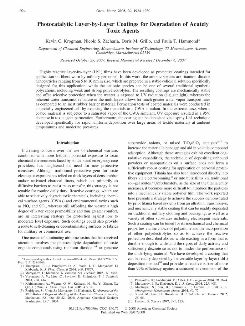
Multilayer coatings were generated via the alternatingmisting of a 10 wt % solution of titanium dioxide nanopar-ticles and a 20 mM solution of PDAC. All solutions,including rinsewater, were titrated to pH 10 prior todeposition. As shown in Figure 1, the growth of the (TiO2/PDAC)n films proceeds linearly at a constant rate ofapproximately 10 nm per deposition cycle, suggesting thatTiO2 particles are adsorbed to the developing surface as amonolayer during each exposure to colloidal solution. Anexample thermogravimetric analysis (TGA) performed onone such film constructed under these conditions can alsobe seen in Figure 1. Starting at ambient conditions, we findthat approximately 2.6% of the film’s weight at equilibriumis water, whereas 41% of the film is combustible organicmaterial. Upon heating to 800 °C and holding for severalhours, it is observed that titania comprises approximately56% of the film by weight.
The resulting film is mechanically stable, as a result ofthe strong electrostatic interactions between the charged
species. Hence, even though it is comprised of 56 wt % rigidnanoparticles, it is able to resist gentle rubbing. This resultcan be attributed to the strong charge observed on the surfaceof the synthesized colloidal nanoparticles, as well as theintermolecular entanglements of the codeposited polyion.
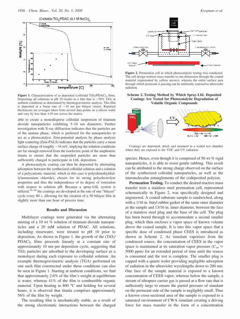
Permeation Testing. To conduct the desired reactive masstransfer tests a stainless steel permeation cell, representedschematically in Figure 2, was specifically designed andengineered. A coated substrate sample is sandwiched, alongwith a 1/16 in. butyl rubber gasket of the same outer diameteras the sample and 13/16 in. inner diameter, between the faceof a stainless steel plug and the base of the cell. The plughas been bored through to accommodate a second smallerplug, which then encloses a vapor space of known volumeabove the coated sample. It is into this vapor space that aspecific dose of condensed phase CEES is introduced asshown in Scheme 2. As simulant vaporizes from thecondensed source, the concentration of CEES in the vaporspace is maintained at its saturation vapor pressure (Csat ≈5000 ppm) for an extended period of time until the sourceis consumed and the test is complete. The smaller plug iscapped with a quartz wafer providing negligible adsorptionof radiation in the ultraviolet wavelengths down to 200 nm.One face of the sample material is exposed to a knownconcentration of CEES vapor, whereas below the sample, astream of ultrapure carrier gas is passed at a flow rate that issufficiently large to ensure the partial pressure of simulanton the permeant side of the sample is negligibly small. Thusa known cross-sectional area of the sample is exposed to asaturated environment of CWA simulant creating a drivingforce for mass transfer in the form of a concentration
Figure 1. Characterization of as deposited (colloidal TiO2/PDAC)n films.Depositing all solutions at pH 10 results in a film that is ∼56% TiO2 atambient conditions as determined by thermogravimetric analysis. This filmis deposited at a linear rate of ∼10 nm per bilayer (inset). Reportedthicknesses are averages taken from several data points on a silicon waferand vary by less than (10 nm across the matrix.
Figure 2. Permeation cell in which photocatalytic testing was conducted.The cell design restricts mass transfer to one dimension through the coatedmaterial (represented by yellow arrows), whereas the entire surface areathrough which permeant is passing can be uniformly exposed to ultravioletradiation.
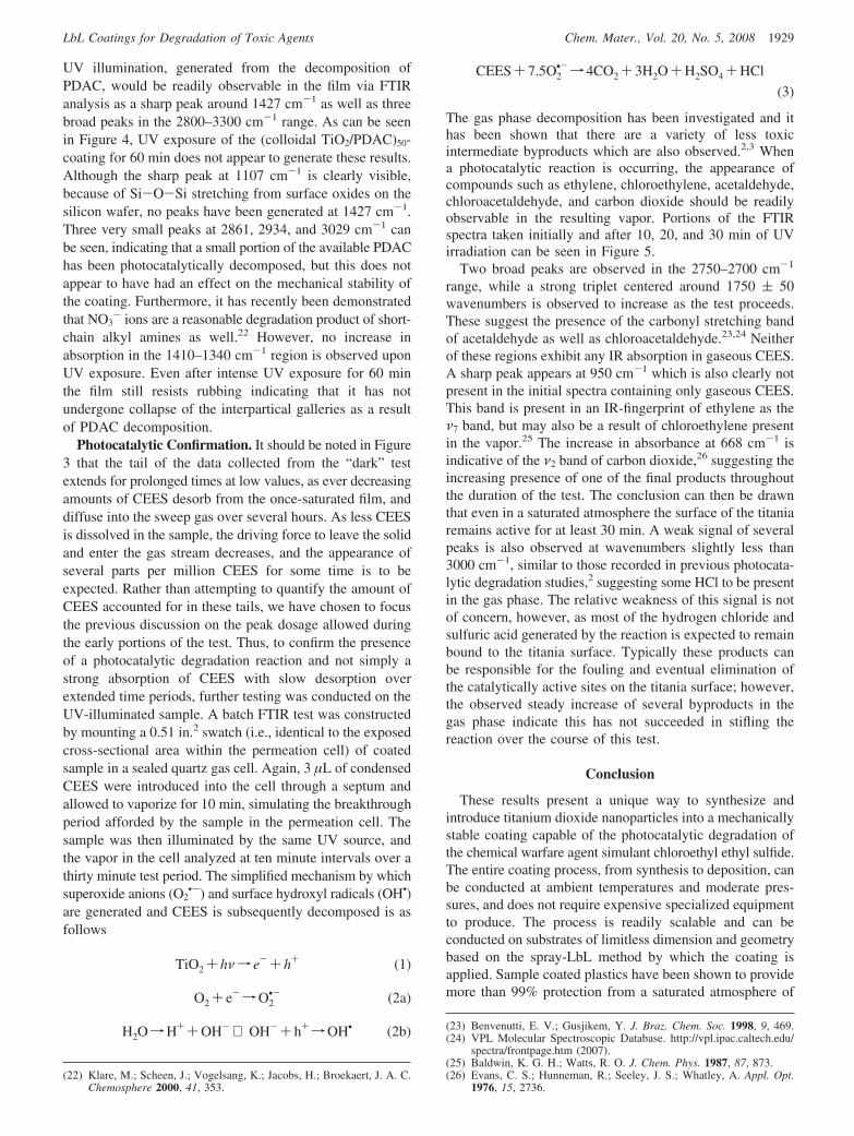
Scheme 2. Testing Method by Which Spray-LbL DepositedCoatings Are Tested for Photocatalytic Degradation of
Volatile Organic Compounds
Coatings are deposited, dried, and mounted in a sealed test chamberwhere they are exposed to the VOC and UV radiation.
1926 Chem. Mater., Vol. 20, No. 5, 2008 Krogman et al.

gradient. The exposed cross-sectional diameter has beenchosen so as to eliminate edge diffusion effects (i.e., samplethickness , cross-sectional diameter) simplifying the analy-sis by causing mass transfer to be predominantly unidirectional.
Vaporized CEES from the vapor space dissolves into theLbL coating of the sample which may or may not bephotocatalytically active during the test. CEES, or theappropriate products of degradation, then diffuse through theinert substrate before leaving the sample into the carrier gason the permeant side of the substrate. The carrier gas is thenanalyzed by combustion in the hydrogen/oxygen flame of atotal hydrocarbon analyzer equipped with an FID capableof contaminant detection at 0.01 ppm levels. Similarly, thetest can also be run in conjunction with an ultraviolet spotsource, equipped with a mercury vapor lamp to mimicsunlight. The lamp is capable of illuminating the exposedportion of the sample through the quartz cap above the vaporspace, eliminating the risk of contamination between the UVlamp and the vapor space.
The mass flux of contaminant through the sample can thenbe determined by measuring the concentration of contaminantin the sweep gas, as well as the flow rate at which the sweepgas is passing under the sample. Similarly, the rate at whichcontaminant passes through the sample can be normalizedby the cross-sectional area through which mass transfer isallowed to occur, specified by the cell geometry, and thedriving force for mass transfer in the form of a partialpressure gradient. Termed the permeance, the normalized fluxcan be calculated, P ) q / A∆p ) f(Fcarrier,ppmCEES) , bymeasuring the flow rate of carrier gas as well as theconcentration of CEES contaminant in the stream. Thecalculation gives a thickness independent interpretation ofthe exposure a user would expect to experience while underthe protection of such a coated substrate.
Photocatalytic Capabilities. For the purpose of testingthe photocatalytic capabilities of the (PDAC/TiO2)n, a 50-cycle deposition was performed using the spray-LbL tech-nique. The film was constructed on a 12.7 µm thicknonporous poly(vinylidene chloride) sheet available underthe trade name Saran 8 from the Dow Chemical Company.This substrate material was chosen for several reasons. Theinherent negative surface charge on the plastic sheet enablesthe adherence of the first few monolayers to the substratevia electrostatic interactions. Further, by choosing a nonpo-rous substrate with easily characterizable gas permeationproperties, it is possible to determine mass-transfer charac-teristics of the uncoated substrate to serve as a benchmarkfor future comparisons with the coated material. Saran is abiaxially oriented monolayer barrier film which is moderatelyCEES permeable, a property that is quantified below. It isalso inert to chlorinated compounds such as CEES, makingit an ideal substrate for permeation testing of (PDAC/TiO2)n
reactive coatings.
The coated sample was then mounted in the permeationcell, and 3 µL of condensed phase CEES were introducedinto the vapor space above the sample. As the vaporpermeated through the sample it was collected and sweptaway to the Total Hydrocarbon Analyzer (THA) which wascalibrated for CEES identification. The resulting mass flux,
in grams of CEES per minute, can be seen in Figure 3.During the first 15 min of testing no contaminant is observedin the permeant vapor. After this breakthrough time, tb,dark,however, the concentration of CEES in the sweep gascontinues to increase as the sample becomes loaded withCEES. The parabolic downturn occurs as the condensedsource of CEES in the vapor space becomes depleted and isno longer able to maintain a constant vapor pressure abovethe sample. A maximum concentration of CEES in thepermeant stream is observed at 33 ppm. The test is conductedfor 2 h, which is sufficient for the large majority of the CEESto exit the system.
Upon complete evacuation of CEES from the system,further testing can be conducted. An identical film wassubjected to a similar 3 µL loading. This time, however,ultraviolet light was passed through the quartz cap of thecell, illuminating the area of the coated sample simulta-neously exposed to the saturated atmosphere of CEES. Again,permeant vapor is removed by the sweep gas and analyzedby the THA. The observed instantaneous mass flux can alsobe seen in Figure 3. In this scenario, no contaminant isdetected by the THA prior to a shorter 8 min breakthroughtime, tb,UV. This can be explained by the solution-diffusionmechanism by which CEES transfers across the material.Permeability is typically expressed as the product of thediffusivity of a molecule through the solid matrix and thesolubility of the vapor molecule in the solid.21 As the intenseUV radiation falls on the titania particles some of the energyis used to generate electron–hole pairs that eventually resultin the superoxide anions that make titania useful as aphotocatalyst. The remainder of the energy is absorbed asradiant heat, slightly increasing the temperature of theunderlying solid material. This rise in temperature will serveto increase both the diffusivity and the solubility of CEESthroughout the sample. A slight increase in permeation rateis thus not surprising, and the contaminant molecules appeartwice as rapidly in the permeant stream.
Aside from the temperature-induced decrease in resistanceto mass transfer, it is clear that the overall CEES permeation
(21) Wijmans, J. G.; Baker, R. W. J. Membr. Sci. 1995, 107, 1.
Figure 3. Mass flux of CEES through a coated sample as measured in thecarrier gas passing below the sample. Identical samples were exposed to 3µL loadings of CEES and allowed to permeate. The test was conductedboth with (X) and without (O) UV illumination.
1927Chem. Mater., Vol. 20, No. 5, 2008LbL Coatings for Degradation of Toxic Agents

has been greatly reduced. This effect becomes even morepronounced as time passes. The peak concentration of CEESin the permeant vapor occurs at roughly the same elapsedtime, but the degradation of CEES vapor in the photocatalyticcoating has reduced this peak value to less than 1.5 ppm.Thus the reduction in maximum CEES concentration on thepermeant side of the sample membrane was decreased bymore than 95% when subjected to UV light. It is alsobeneficial to analyze the protective capabilities of the filmfrom a net exposure standpoint. Because these tests havebeen conducted with 3 µL loadings of CEES, a stoichiometricconstraint imposed by the amount of oxygen present in thevapor space available to participate in the photocatalyticreaction at the titania surface, this type of analysis is onlyappropriate up to the point where the condensed CEES sourceappears to run out. After this time, the vapor space is nolonger maintained at the saturation concentration as CEESis reactively consumed by the film, and the partial pressuregradient driving mass transfer begins to decrease. Thisappears to occur at approximately 40 min of test time. Upto this point, only 5.1 µg of CEES have passed through thephotocatalytically active (i.e., exposed to UV light) sample.This corresponds to less than 1% of the 3.21 mg of CEESintroduced into the vapor space. A more thorough under-standing of the net flux over longer periods of time isnecessary to fully evaluate this material and will be obtainedin the future after some modifications to the test cell.However, it can be concluded from these preliminary resultsthat the (colloidal TiO2/PDAC)50 coating, when illuminatedby UV light, can exhibit reactive protection for at least 40min of more than 99% from a saturated environment ofCEES.
The net mass flux over the 1 h time frame displayed inFigure 3 can also be calculated by integrating the instanta-neous flux over the length of the test. In the dark membranetest, this net flux corresponds to 104 µg, while the UVilluminated test results in 8.2 µg net permeation. By forminga ratio of the net flux observed in the presence of UV lightto that observed without UV light, a 10-fold reduction isseen. This 10-fold reduction can then be expected in furthertesting independent of the fact that a steady state scenariowas never actually reached in these tests. As mentionedabove, a benefit of using a nonporous substrate such as Saran8 is that material mass transfer properties can be determinedusing this type of permeation cell by simply increasing the
condensed CEES loading until a steady state diffusionscenario is obtained. The increased loading provides a largercondensed phase source capable of maintaining the saturatedvapor space until the sample reaches diffusional equilibrium.Prior to these tests it was determined that the steady-stateconcentration of CEES observed in the sweep gas, ofidentical flow rate, below a sample of uncoated Saran 8 was152 ppm. This uncoated control test corresponds to a steadystate mass flux of CEES through Saran 8 of 32.7 µg/min,five times greater than the largest rates observed in either ofthese tests. We can thus assume that the multilayer coatingprovides a significant portion of the resistance to masstransfer across the sample.
It has been suggested by previous work that ultravioletillumination of LbL constructed films composed of titaniananosheets and PDAC will elicit the photocatalytic decom-position of the PDAC in the film, producing inorganicmultilayers composed only of the titania nanosheets andcharge balancing ammonium ions.12 The resulting coatingwould presumably have a marked decrease in mechanicalstability, as well as a change in film permeability over timeas the structure collapses and the titania sheets are freed ofthe PDAC. If this were the case the formation of NH4
+ upon
Figure 4. FTIR spectra of (a) the as-deposited (colloidal TiO2/PDAC)50
coating on IR transparent silicon, and (b) the same coating after 60 min ofUV exposure.
Figure 5. FTIR spectra collected during a closed cell batch analysis. Thecell contained a sample of coated material, equal in size to the exposedsurface during permeation testing, and 3 µL condensed CEES. The entirecell was then irradiated by UV light and spectra taken at 10 min timeintervals.
1928 Chem. Mater., Vol. 20, No. 5, 2008 Krogman et al.
UV illumination, generated from the decomposition ofPDAC, would be readily observable in the film via FTIRanalysis as a sharp peak around 1427 cm-1 as well as threebroad peaks in the 2800–3300 cm-1 range. As can be seenin Figure 4, UV exposure of the (colloidal TiO2/PDAC)50-coating for 60 min does not appear to generate these results.Although the sharp peak at 1107 cm-1 is clearly visible,because of Si-O-Si stretching from surface oxides on thesilicon wafer, no peaks have been generated at 1427 cm-1.Three very small peaks at 2861, 2934, and 3029 cm-1 canbe seen, indicating that a small portion of the available PDAChas been photocatalytically decomposed, but this does notappear to have had an effect on the mechanical stability ofthe coating. Furthermore, it has recently been demonstratedthat NO3
- ions are a reasonable degradation product of short-chain alkyl amines as well.22 However, no increase inabsorption in the 1410–1340 cm-1 region is observed uponUV exposure. Even after intense UV exposure for 60 minthe film still resists rubbing indicating that it has notundergone collapse of the interpartical galleries as a resultof PDAC decomposition.
Photocatalytic Confirmation. It should be noted in Figure3 that the tail of the data collected from the “dark” testextends for prolonged times at low values, as ever decreasingamounts of CEES desorb from the once-saturated film, anddiffuse into the sweep gas over several hours. As less CEESis dissolved in the sample, the driving force to leave the solidand enter the gas stream decreases, and the appearance ofseveral parts per million CEES for some time is to beexpected. Rather than attempting to quantify the amount ofCEES accounted for in these tails, we have chosen to focusthe previous discussion on the peak dosage allowed duringthe early portions of the test. Thus, to confirm the presenceof a photocatalytic degradation reaction and not simply astrong absorption of CEES with slow desorption overextended time periods, further testing was conducted on theUV-illuminated sample. A batch FTIR test was constructedby mounting a 0.51 in.2 swatch (i.e., identical to the exposedcross-sectional area within the permeation cell) of coatedsample in a sealed quartz gas cell. Again, 3 µL of condensedCEES were introduced into the cell through a septum andallowed to vaporize for 10 min, simulating the breakthroughperiod afforded by the sample in the permeation cell. Thesample was then illuminated by the same UV source, andthe vapor in the cell analyzed at ten minute intervals over athirty minute test period. The simplified mechanism by whichsuperoxide anions (O2
•-) and surface hydroxyl radicals (OH•)are generated and CEES is subsequently decomposed is asfollows
TiO2 + hνf e-+ h+ (1)
O2 + e-fO2•- (2a)
H2OfH++OH- ⇒ OH-+ h+fOH• (2b)
CEES+ 7.5O2•-f 4CO2 + 3H2O+H2SO4 +HCl
(3)
The gas phase decomposition has been investigated and ithas been shown that there are a variety of less toxicintermediate byproducts which are also observed.2,3 Whena photocatalytic reaction is occurring, the appearance ofcompounds such as ethylene, chloroethylene, acetaldehyde,chloroacetaldehyde, and carbon dioxide should be readilyobservable in the resulting vapor. Portions of the FTIRspectra taken initially and after 10, 20, and 30 min of UVirradiation can be seen in Figure 5.
Two broad peaks are observed in the 2750–2700 cm-1
range, while a strong triplet centered around 1750 ( 50wavenumbers is observed to increase as the test proceeds.These suggest the presence of the carbonyl stretching bandof acetaldehyde as well as chloroacetaldehyde.23,24 Neitherof these regions exhibit any IR absorption in gaseous CEES.A sharp peak appears at 950 cm-1 which is also clearly notpresent in the initial spectra containing only gaseous CEES.This band is present in an IR-fingerprint of ethylene as theν7 band, but may also be a result of chloroethylene presentin the vapor.25 The increase in absorbance at 668 cm-1 isindicative of the ν2 band of carbon dioxide,26 suggesting theincreasing presence of one of the final products throughoutthe duration of the test. The conclusion can then be drawnthat even in a saturated atmosphere the surface of the titaniaremains active for at least 30 min. A weak signal of severalpeaks is also observed at wavenumbers slightly less than3000 cm-1, similar to those recorded in previous photocata-lytic degradation studies,2 suggesting some HCl to be presentin the gas phase. The relative weakness of this signal is notof concern, however, as most of the hydrogen chloride andsulfuric acid generated by the reaction is expected to remainbound to the titania surface. Typically these products canbe responsible for the fouling and eventual elimination ofthe catalytically active sites on the titania surface; however,the observed steady increase of several byproducts in thegas phase indicate this has not succeeded in stifling thereaction over the course of this test.
Conclusion
These results present a unique way to synthesize andintroduce titanium dioxide nanoparticles into a mechanicallystable coating capable of the photocatalytic degradation ofthe chemical warfare agent simulant chloroethyl ethyl sulfide.The entire coating process, from synthesis to deposition, canbe conducted at ambient temperatures and moderate pres-sures, and does not require expensive specialized equipmentto produce. The process is readily scalable and can beconducted on substrates of limitless dimension and geometrybased on the spray-LbL method by which the coating isapplied. Sample coated plastics have been shown to providemore than 99% protection from a saturated atmosphere of
(22) Klare, M.; Scheen, J.; Vogelsang, K.; Jacobs, H.; Broekaert, J. A. C.Chemosphere 2000, 41, 353.
(23) Benvenutti, E. V.; Gusjikem, Y. J. Braz. Chem. Soc. 1998, 9, 469.(24) VPL Molecular Spectroscopic Database. http://vpl.ipac.caltech.edu/
spectra/frontpage.htm (2007).(25) Baldwin, K. G. H.; Watts, R. O. J. Chem. Phys. 1987, 87, 873.(26) Evans, C. S.; Hunneman, R.; Seeley, J. S.; Whatley, A. Appl. Opt.
1976, 15, 2736.
1929Chem. Mater., Vol. 20, No. 5, 2008LbL Coatings for Degradation of Toxic Agents

simulant when subjected to ultraviolet radiation with aspectrum resembling that of sunlight. Similarly, the polarionic complex nature of LbL films allows the material tohave much greater water vapor transport properties whencompared to inert rubbers capable of similar protectiveproperties. The coating is optically clear and can be depositedon materials without compromising their underlying func-tionality. Finally, because the titania is deposited as part ofan exterior coating there is less risk that superoxide anionsdeveloped even under intense UV light will degrade theunderlying material. While small portions of the polycation
in the film are degraded by the photocatalytic activity of thetitania, the mechanical stability of the coating is notcompromised.
This research was supported in part by the U.S. Armythrough the Institute for Soldier Nanotechnologies undercontract DAAD-19–02-D-0002 with the U.S. Army ResearchOffice. The content does not necessarily reflect the positionof the government, and no official endorsement should beinferred.
CM703096W
1930 Chem. Mater., Vol. 20, No. 5, 2008 Krogman et al.