Embed Size (px)
Citation preview
Session 2526
PHOTOELASTICITY AND ITS SYNERGISM WITH FINITEELEMENT METHOD
Said Shakerin, Daniel D. JensenDepartment of Mechanical Engineering / Department of Engineering Mechanics
University of the Pacific / U.S. Air Force Academy
Abstract
The goal of this project is to enhance mechanical engineering education by incorporatingexperiments in photoelastic stress analysis within the existing curriculum. Photoelasticityis a visual, full-field technique for determining stresses in parts and structures. In additionto its traditional use in industry, there is a renewed interest in using photoelasticity to testobjects made by stereolithography.
Specific instructional objectives are to: (a) increase conceptual understanding of stressdistribution through photoelastic and finite element based visualization, (b) gainexperience with photoelasticity and its advantages/limitations, and (c) appreciate thesynergism between experimental and numerical methods of stress analysis.
Through a National Scieence Foundation matching grant, one transmission polariscopeset, one reflection polariscope set, and accompanying accessories have been purchasedand installed for students’ use. The equipment has also been used for in-classdemonstrations and motivational presentations to K-12 students.
All mechanical engineering students at the University of the Pacific have benefited fromthis project. Several experiments have been introduced in the curriculum, and severalstudent projects have been completed utilizing the equipment purchased with this grant.A similar combination of photoelastic demonstration plus finite element results is beingused at the U.S. Air Force Academy to enhance mechanics education there.
Overall, students have experienced that in solving engineering problems one has tochoose the appropriate tool of analysis, and recognize that quite often several tools mustbe utilized to validate the results, e.g., validation of numerical solutions by experimentalmeans. Although the project duration is not completed yet, some of developments madepossible by this grant have been disseminated.
I. Introduction
Stress analysis plays a significant role in the design of parts and structures that must carryload. With the proper knowledge and tools, a designer identifies areas with high stresses
Page 4.419.1
(i.e., potential failure points), as well as areas with low stresses (i.e., potential for materialremoval, weight reduction, and cost saving). A mechanical engineer should haveexperience with the most commonly used tools of stress analysis. A summary oftheattributes of the three most commonly used stress analysis methods, outside of the textbook analytical equations, is presented below [1].
METHOD ADVANTAGE DISADVANTAGEStrain gage Relatively easy to apply. Remote
data collection.Point measurement only.
Photoelasticity Full-field measurement. Must have visual access. Limitedtemperature range.
Numerical Methods Handles complex shapes.Suitable for parametric studies.
Difficulty in building accurate model.
There are a number of applications in which the use of strain gages and numericalmethods would not be desirable or applicable to solve for the stresses. Examples include:(a) assembly stress caused by the mechanical assembly of component parts, such as thatwhich occurs during bolting; (b) residual stress that resides in the structure which resultsfrom manufacturing processes, such as welding and casting; (c) stresses caused bycomplex working forces that make it difficult to accurately define the loading andboundary conditions; and (d) stresses resulting from geometric imperfections, fabricationtolerances, and poor fits in the actual structure. Also, prediction of localized yielding isdifficult since it is random.
The photoelastic test method, which provides both qualitative (visual) information as wellas quantitative data, serves as a very appropriate tool of analysis for the above cases.This method has received significant attention in industry as reflected in papers publishedin the recent proceedings of the Society of Experimental Mechanics (SEM); e.g., seereferences 2-6. Furthermore, photoelastic testing recently has been used directly withprototypes made by stereolithography, hence, shortening the design-construction-testing-redesign cycle time [7, 8]. Recently, two dedicated conferences have been organized bySEM to focus on the synergism between finite element analysis and structural testingwith rapid prototyping.
In addition to the technical significance of the photoelastic method there is also apedagogical advantage. Substantial research in the area of learning styles of students hasshown that a large percentage of them will learn more effectively when concepts arereinforced visually [e.g., 9-12]. The photoelastic technique can effectively provide thevisual reinforcement of various concepts related to stress analysis on actual parts.Therefore, integration of photoelasticity into our curriculum is a significant improvement.
II. Learning Objectives
The learning objectives of this project are for students to:
(a) increase their conceptual understanding of stresses through both photoelastic andfinite element based visualization,
Page 4.419.2
(b) gain experience with the photoelastic test method to appreciate its advantages andlimitations, and
(c) realize the synergism between experimental and numerical methods for stressanalysis.
As mentioned previously, these objectives have also been implemented at the U.S. AirForce Academy. Specifics of their use are presented in reference 13.
Specific courses, at the University of the Pacific, affected by this project are presentednext. Since these courses are offered in different semesters, there is no problem withequipment use overload. The experiments designed for this work are outlined in theAppendix. The instructor can choose one or two experiments as appropriate for a givencourse.
III. Impact of the Project
Four courses, Mechanics of Materials, Machine Design, Instrumentation andExperimental Methods (all required), and the Finite Element Method (elective) have beenimproved through integration of carefully planned experiments and student projects instress analysis. The equipment has also been used at occasions when faculty makepresentations to K-12 students to attract them to engineering. One example is ourworkshop series conducted for high school students interested in engineering and science.Furthermore, a series of simple experiments, showing a variety of applications, is beingdeveloped for dissemination to the nearby high school science teachers.
Mechanics of Materials (ENGR121) - This course is required for all mechanical and civilengineering majors. One class demonstration has been added to enhance students’understanding of stress distribution through visualization. The demonstration includesbrief discussion of photoelastic testing method and several short experiments on 2-Dbeams under different loading conditions. An example is shown in Figure 1. All figuresare shown at the end of the paper for clarity.
Instrumentation and Experimental Methods (MECH110) - This is a required course forall mechanical engineering students and an elective for other engineering majors. Aformal laboratory with six well-defined experiments in different areas accompanies thiscourse. There is also a term project that requires students to design, construct, and test adevice, and write an engineering report. Two experiments have been designed for thelaboratory to illustrate applications of photoelasticity in stress analysis (selected fromthose listed in the Appendix), and students are encouraged to incorporate photoelastictesting in their term projects. One example is study of a C-clamp with strain gages and a2-D photoelastic model, see Figure 2. A two-hour lecture has been added to this class toreinforce the principles, advantages, and disadvantages of photoelasticity as applied to 2-D model studies and actual objects coated with photoelastic material.
Machine Design (MECH120) - There is no formal laboratory component for this requiredcourse. Since stress distribution is an important topic in the design of machine elements,
Page 4.419.3
one project has been assigned that required students to design a fixture that could be usedto apply constant bending moment to a beam while being pulled upon. One example ofsuch design is shown in Figure 3a. This happened to be an excellent addition to ourequipment since students can now visualize the superposition principle in terms ofcombined loading of a beam, Figure 3b.
Finite Element Method (MECH178) - This is an elective course for mechanical and civilengineering majors. Students taking this course are asked to conduct a project thatincorporates finite element analysis and photoelastic testing of a real object. Students,therefore, use the results of photoelasticity test to complement and verify the resultobtained by the finite element analysis. An example is shown in Figure 4, where thestudent studied stress distribution in a crane hook. In another project, a motorcycle brakehandle was analyzed and a good qualitative agreement between the numerical solutionand photoelasticity test results was observed. It is interesting to note that successfulintegration of physical experiments into numerical methods courses has been reported inthe literature [14].
IV. Equipment
Two major pieces of equipment were purchased for this work. The teaching transmissionpolariscope, which can be mounted on an overhead projector, is used for teaching theprinciples of photoelasticity and measurements related to 2-D model studies. Thereflection polariscope is used for testing actual parts (under actual loads) that have beencoated with a photoelastic material, see Figure 5.
An optical null compensator is used for each of the polariscopes to obtain quantitativedata (i.e., the fringe order) from the fringe patterns produced. These data, in conjunctionwith the optical factor of the photoelastic coating, are essential in determining stresses.The loading frame (Figure 3a) allows convenient loading of models for the purpose ofteaching, demonstration, and experimentation. The photoelasctic coating on severalobjects were prepared by outside source, and the 2-D objects have been fabricated in-house, as needed.
A video camera plus a frame grabber interface is yet to be purchased to capture theresults of photoelastic experiments on a personal computer (PC). This will enablestudents to compare experimental and numerical results on the PC, without a need tophotographically record the photoelastic result.
With the equipment described, students are able to make quantitative measurements onmodels as well as on actual parts. They can also make qualitative comparisons. As aresult, our graduates will have experience with empirical work in the area of stressanalysis, which will enhance their ability in designing machine parts and structuralelements.
Page 4.419.4
V. Evaluation
The results of this project (i.e., laboratory experiments, student projects, classdemonstrations, and outreach activity) have positively affected the learning of the usersof the equipment. This has been acknowledged through evaluations done by students andothers. Several colleagues at other institutions have asked for information on some of theprojects described here. Overall, this project will continue to enhance education of ourstudents for the next several years.
VI. Acknowledgments
The National Science Foundation through grant DUE9751315 and the School ofEngineering at the University of the Pacific provided the equipment funding. UOPstudents whose projects are examplified in this paper are Brian Alamo, Bill Cook, JuanAguirre, Lani Dodge, and Kevin Baskin; student Will Solymanbeyk scanned thephotographs. Thomas Corby Jr., Senior Vice Presdient at Measurements Group, Inc.,provided the photoelastic coating of several objects used in this project.
References
1. “Seminar on Experimental Stress Analysis Techniques for the Teaching Laboratory,” Seminar Notebook,Measurements Group, Raleigh, NC, 1995.2. Monkovich, B., “Photoelasticity in the Printer Industry,” Proceedings of the Society for ExperimentalMechanics Conference and Exhibition, Milwaukee, Wisconsin, 1991.3. Gambrell, Jr., S. C., “Use of PhotoStress Techniques to Characterize the Mechanical Behavior ofWeldments,” Proceedings of the Society for Experimental Mechanics Conference and Exhibition, LasVegas, Nevada, 1992.4. Finlay, J.B. and Little, E.G., “Photoelasticity as a Tool in Orthopedic Research,” Proceedings of theSociety for Experimental Mechanics Conference and Exhibition, Dearborn, Michigan, 1993.5. Slaminko, R., “Contributions of Photoelasticity to the Development of Boeing 777,” Proceedings of theSociety for Experimental Mechanics Conference and Exhibition, Dearborn, Michigan, 1993.6. Allison, I.M., “Photoelastic Studies of the Stresses in Large Buttress Dams,” Proceedings of the Societyfor Experimental Mechanics Conference and Exhibition, Baltimore, Maryland, 1994.7. Steinchen, W., Kramer, B., and Kupfer, G., “Photoelasticity Cuts Part-Development Costs,” PhotonicsSpectra, pp.157-162, May 1994.8. “Rapid Prototyping Helps Spot Engine-Blade Stress,” Design News, p. 37, Sept. 1994.9. Stice, J. E., “Using Kolb's Learning Cycle to Improve Student Learning," Engineering Education, Vol.77, No. 5, pp. 291-296, 1987.10. Felder, R.M. and Silverman, L.K., "Learning and Teaching Styles in Engineering Education,"Engineering Education, Vol. 78, No. 7, pp. 674-681, 1988.11. Tan, F. L. and Fok, S. C., "Development of Engineering Courseware for University UndergraduateTeaching Using Computer Animation," Computer Applications in Engineering Education, Vol. 3 (2), pp.121-126, 1995.12. Ullman, K. M. and Sorby, S. A., "Enhancing the Visualization Skills of Engineering Students ThroughComputer Modeling," Computer Application in Engineering Education, Vol. 3 (4), pp. 251-257, 1995.13. Brochert, R., Jensen, D., “Hands-on and Visualization Models for Enhancement of Learning inMechanics: Development and Assessment in the Contest of Myers-Briggs and VARK Learning Styles,”ASEE Annual Conference, Session # 1368, Paper # 4, 1999.14. Moaveni, S., “Integrating Solid Mechanics and Design in an Undergraduate Finite Element Class,”Proceedings of ASEE Annual Conference, pp. 1902-1905, 1994.
Page 4.419.5
SAID SHAKERIN joined the Department of Mechanical Engineering at the University of the Pacific in1986 and is now a professor. He also served as department chairman at UOP from 1995 to 1998. He earneda Ph.D. from Colorado State University in 1986 and is a registerted professional engineer in California.His scholarly interests include research in thermal/fluid sciences, design in nature and engineering, anddevelopment of innovative teaching tools. In 1991, he received the Dow Outstanding Young FacultyAward from the PSW-ASEE.
DANIEL D. JENSEN received his B.S. in Mech. Eng. (’85), M.S. in Eng. Mechanics (’88) and Ph.D. inAero. Eng. (’92) all from the University of Colorado at Boulder. His industrial experience includes TexasInstruments (mechanical design), Naval Research Labs (Ph.D. work), NASA Langley funded post doc andconsulting at Lockheed and Lawrence Berkeley National Labs. He taught at University of the Pacific for 4years and now teaches at the USAF Academy in the areas of design and analysis.
Appendix
Experiment # 1- Stress concentration in a beam. Equipment needed are a transmissionpolariscope with a null compensator, several birefringent beam models with various kindsof discontinuity, and a loading fixture. Students become familiar with the use of thepolariscope to visualize the fringe pattern produced in the model. The fringe patternindicates stress distribution. Stress data can be obtained with the use of a nullcompensator, and the stress concentration factor at the discontinuity is determined andcompared with the published data. Students also observe how stress concentrationdiminishes a short distance from a discontinuity. The experience gained reinforcesmaterial covered in the class.
Experiment # 2 - Calibration of photoelastic material. Equipment needed are a reflectionpolariscope with a null compensator, an aluminum beam coated with a photoelasticmaterial whose optical factor is to be determined, and a loading fixture. Students becomefamiliar with the use of the reflection polariscope and the method to find (i.e., calibrate)the optical factor of photoelastic coating. This factor plays a crucial role in obtainingstress data in actual parts coated with photoelastic material. The photoelastic opticalfactor is analogous to the gage factor in strain gages.
Experiment # 3 - Stresses in a pressure vessel (to be completed). Equipment needed are areflection polariscope with a null compensator, a pressure vessel coated with photoelasticmaterial, “separator” strain gages, a strain indicating device, and compressed air. A 3-in.pipe tee is used as a pressure vessel. (A safety relief valve is included.) Compressed airavailable in the laboratory is used to pressurize the vessel. Using the optical factor(determined in Experiment # 2) and the fringe pattern produced in the polariscope,students determine the difference in principal stresses (σ1- σ2) from the photoelasticitytest directly. They also identify areas of high stresses. “Separator” strain gages areinstalled to strategic locations to obtain the sum of principal stresses (σ1 + σ2). Then, withsimple calculations, each of the principal stresses and directions can be determined. Inaddition, a numerical solution to the pressure vessel has been prepared to be given tostudents for comparison purpose. Differences between the photoelasticity and numericalresults will be discussed and advantages and limitations of the different methods broughtout. P
age 4.419.6
Experiment # 4 - Stresses on a shaft in torsion. Equipment required are a reflectionpolariscope with a null compensator, several shafts with different cross sectional areascoated with photoelastic material, and a torsion tester. The effect of rounded fillet andsharp changes in diameter on stress distribution is investigated. Students identify stressconcentration areas experimentally. In addition, the instructor will provide a finiteelement solution for the same shaft. Advantages and disadvantages of photoelasticity andnumerical solutions for stresses in machine elements will be discussed.
Experiment # 5 - Load cell optimization. Equipment needed are a transmissionpolariscope with a null compensator, several birefringent load cell models, and a loadingfixture. Load cells utilizing strain gages are used in numerous measurement applicationssuch as electronic balances. The placement of the strain gages on the load cell is a crucialdesign factor. They should be placed at maximum stressed points to improve sensitivityof the load cell. Students conduct photoelasticity experiments on a 2-D model of a loadcell and perform a finite element analysis to identify maximum and minimum stressedpoints. Also, the effect of slight construction changes on the load cell can be easilydetermined with the model study. Feedback from the photoelasticity tests can be used tohelp students know where and how much to refine the finite element model to increaseaccuracy of their solutions.
Experiment # 6 - Stresses on a crane hook. Equipment needed are a reflectionpolariscope with null compensator, a crane hook coated with photoelastic material, and atensile machine. The objective is to determine the magnitude of the maximum stress.Students obtain stress distribution from photoelasticity testing (the fringe pattern) andfinite element analysis (the stress contour map). Some tuning of the finite element model(e.g., boundary and loading conditions) may be required to obtain a finite element stresscontour that resembles that of the photoelasticity. Once this resemblance is obtained, thefinite element results can be reliably used to determine maximum stresses. Thisprocedure eliminates the need for “separator” strain gages to determine the stressmagnitudes. In other words, this experiment demonstrates the synergism between thefinite element method and photoelasticity technique.
Page 4.419.7
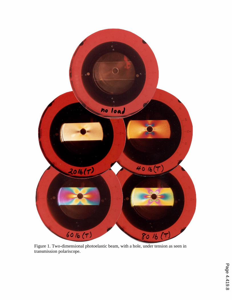
Figure 1. Two-dimensional photoelastic beam, with a hole, under tension as seen intransmission polariscope.
Page 4.419.8
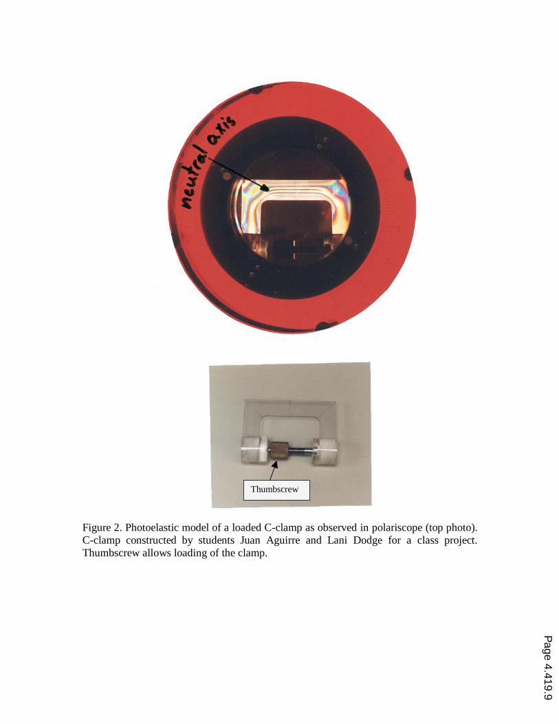
Figure 2. Photoelastic model of a loaded C-clamp as observed in polariscope (top photo).C-clamp constructed by students Juan Aguirre and Lani Dodge for a class project.Thumbscrew allows loading of the clamp.
Thumbscrew
Page 4.419.9
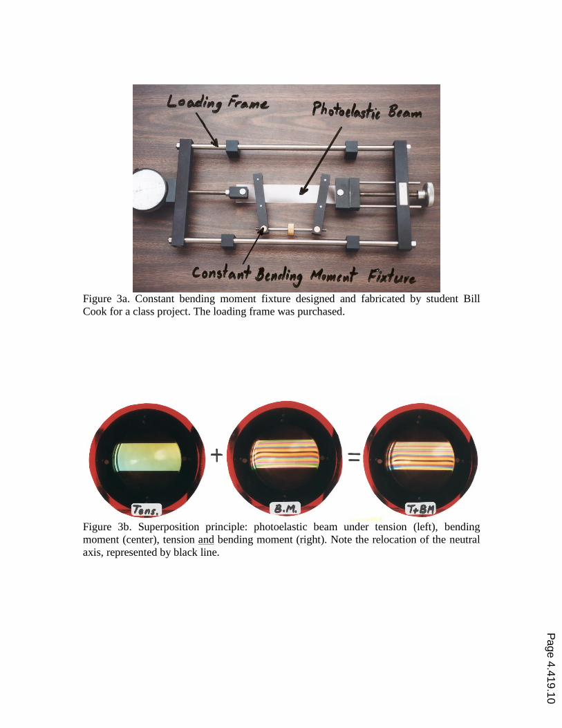
Figure 3a. Constant bending moment fixture designed and fabricated by student BillCook for a class project. The loading frame was purchased.
Figure 3b. Superposition principle: photoelastic beam under tension (left), bendingmoment (center), tension and bending moment (right). Note the relocation of the neutralaxis, represented by black line.
Page 4.419.10
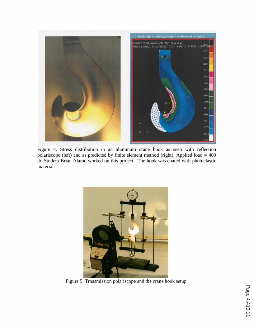
Figure 4. Stress distribution in an aluminum crane hook as seen with reflectionpolariscope (left) and as predicted by finite element method (right). Applied load = 400lb. Student Brian Alamo worked on this project. The hook was coated with photoelasticmaterial.
Figure 5. Trnasmission polariscope and the crane hook setup. Page 4.419.11