Embed Size (px)
Citation preview

S50 SERIES
The S50 series offers all optical functions within a m18 housing.with the universal sensing functions of proximity, polarised retroreflex and through beam, which are also available with class 1 laser emission, as well as the more advanced functions of background suppression, contrast and luminescence, the s50 really isone housing for all applications.the s50 setting is carried out-by either by potentiometer, which is sealed to IP67, or using the patented easytouch™ push-button teach system, which gives rapidand precise automatic setting of the switching points.the s50 series is available both in flat plastic format ideal for m18 nut or screwmounting through the sensor body, as well as a cylindrical metal housing. Axial or radial optics are available in both housings with integral cable or m12 connection conforming to en 60947-5-2, the european wiring standard. the performance, versatility and extensive optical sensing options, positions the s50 series as the new bench mark for customers focused on the evolution of technology and development of standards.
HIGHLIGHTS
• complete range of optic functions, universal, application and laser class 1
• flat plastic tubular housing for improved versatility or metal cylindrical housing
• versions with axial or radial optics, with fixed, trimmer or easytouch™ teach-in adjustment
• cable or m12 connection with en standard nPn or PnP no-nc configuration
APPLICATIONSCeramics
Transportation lines
Beverage & Bottling
PHOTOeLeCTRIC
Packaging lines
SeN
SOR
S
TUBULAR SeNSORS
Phone: 800.894.0412 - Fax: 888.723.4773 - Web: www.clrwtr.com - Email: [email protected]

Longer operating distances can be obtained utilising separate emitter and receiver units. The infrared emission is modulated to avoidinterference with other light sources and the emitter is fitted with test inputs for remote system interrogation.
DIMeNSIONSemItter
receIver
INDICATORS AND SeTTINGSoutPut status and stability Leds (receiver); power on Led (emitter)
Adjustment trimmer (receiver)
m12 connector output
cable output
fixing nuts
fixing gasket
A
C
D
e
F
B
radIaL oPtIcs
s50-Pa/Pr-2 s50-Pa/Pr-5
single-turn trimmer for sensitivity adjustment. rotate in a clockwise direction to increase the operating distance.
CONNeCTIONSACCeSSORIeSfor dedicated accessories refer to the ACCeSSORIeS section of this catalogue.
refer also to Connectors and Fixing brackets of the General catalogue. emItter
receIver
versions and options: refer to MODeL ALPHABeTICAL INDex of this catalogue.
G/F INFRARED EMISSION
A
B
Phone: 800.894.0412 - Fax: 888.723.4773 - Web: www.clrwtr.com - Email: [email protected]

TeCHNICAL DATATeCHNICAL NOTeS1Limit values2 average life of 100.000 h with ta = +25 °c3 270° single-turn trimmer4 emitter off with test+ on vdc and test- on 0 v5 Pvc, 4 x 0.14 mm2
6 compatible with quick connection systems 7 a - reverse polarity protection b - overload and short-circuit protection on receiver outputs S5
0-PA
-2-F
01-N
N
S50-
PA-2
-F01
-PP
S50-
PA-2
-G00
-XG
S50-
PR-2
-F01
-NN
S50-
PR-2
-F01
-PP
S50-
PR-2
-G00
-XG
S50-
PA-5
-F01
-NN
S50-
PA-5
-F01
-PP
S50-
PA-5
-G00
-XG
S50-
PR-5
-F01
-NN
S50-
PR-5
-F01
-PP
S50-
PR-5
-G00
-XG
Operating distance:axial optics 0 ... 30 m ● ● ● ● ● ●radial optics 0 ... 25 m ● ● ● ● ● ●
Power supply: 10 ... 30 vdc1 ● ● ● ● ● ● ● ● ● ● ● ●Ripple: ≤ 2 vpp ● ● ● ● ● ● ● ● ● ● ● ●
Consumption:emitter ≤ 35 ma ● ● ● ●receiver ≤ 30 ma ● ● ● ● ● ● ● ●
Light emission: infrared Led 880 nm2 ● ● ● ●Spot dimension:
axial optics approx. 500 mm at 15 m ● ●radial optics approx. 470 mm at 10 m ● ●
Setting: sensitivity trimmer 3 ● ● ● ● ● ● ● ●Indicators: yellow outPut Led ● ● ● ● ● ● ● ●
green stabILIty Led ● ● ● ● ● ● ● ●green Power on Led ● ● ● ●
Output type: PnP, no and nc ● ● ● ●nPn, no and nc ● ● ● ●
Output current: ≤ 100 ma ● ● ● ● ● ● ● ●Saturation voltage: ≤ 2 v ● ● ● ● ● ● ● ●
Response time: 2 ms ● ● ● ● ● ● ● ●Switching frequency: 250 hz ● ● ● ● ● ● ● ●
Operating mode: dark on no / light on nc ● ● ● ● ● ● ● ●Auxiliary functions: test + and test -4 ● ● ● ●
Connection: 2 m Ø 4 mm cable5 ● ● ● ● ● ●m12 4-pole connector6 ● ● ● ● ● ●
electrical protection: class 2 ● ● ● ● ● ● ● ● ● ● ● ●Mechanical protection: IP67 ● ● ● ● ● ● ● ● ● ● ● ●
Protection devices: a, b7 ● ● ● ● ● ● ● ● ● ● ● ●Housing material: Pbt ● ● ● ● ● ● ● ● ● ● ● ●
Lens material: Pmma ● ● ● ● ● ● ● ● ● ● ● ●Weight: 75 g max. ● ● ● ● ● ●
25 g max. ● ● ● ● ● ●Operating temperature: -25 ... +55°c ● ● ● ● ● ● ● ● ● ● ● ●Storage temperature: -25 ... +70°c ● ● ● ● ● ● ● ● ● ● ● ●Reference standard: en 60947-5-2 ● ● ● ● ● ● ● ● ● ● ● ●
SeLeCTION TABLe receiver - axial optics - 2 m cable
s50-Pa-2-f01-nn 952001660 nPn
s50-Pa-2-f01-PP 952001150 PnP
emitter - axial optics - 2 m cable
s50-Pa-2-g00-xg 952001190
receiver - radial optics - 2 m cable
s50-Pr-2-f01-nn 952001820 nPn
s50-Pr-2-f01-PP 952001170 PnP
emitter - radial optics - 2 m cable
s50-Pr-2-g00-xg 952001210
receiver - axial optics - m12 connector
s50-Pa-5-f01-nn 952001550 nPn
s50-Pa-5-f01-PP 952001160 PnP
emitter - axial optics - m12 connector
s50-Pa-5-g00-xg 952001200
receiver - radial optics - m12 connector
s50-Pr-5-f01-nn 952001760 nPn
s50-Pr-5-f01-PP 952001180 PnP
emitter - radial optics - m12 connector
s50-Pr-5-g00-xg 952001220
DeTeCTION DIAGRAMS
recommended operating distancemaximum operating distance
All the ordering codes and information are summarised in the last pages of this catalogue.
excess gain Detection area
Axial
radial
Axial
radial
*only on axial optic models
II3dg*
Phone: 800.894.0412 - Fax: 888.723.4773 - Web: www.clrwtr.com - Email: [email protected]

Longer operating distances can be obtained utilising separate emitter and receiver units. The infrared emission is modulated to avoid interference with other light sources and the emitter is fitted with test inputs for remote system interrogation.
DIMeNSIONSemItter
receIver
INDICATORS AND SeTTINGSoutPut status and stability Leds (receiver); power on Led (emitter)
Adjustment trimmer (receiver)
m12 connector output
cable output
fixing nuts
A
C
D
e
B
radIaL oPtIcs
s50-ma/mr-2 s50-ma/mr-5
single-turn trimmer for sensitivity adjustment. rotate in a clockwise direction to increase the operating distance.
versions and options: refer to MODeL ALPHABeTICAL INDex of this catalogue.
CONNeCTIONSACCeSSORIeSfor dedicated accessories refer to the ACCeSSORIeS section of this catalogue.
refer also to Connectors and Fixing brackets of the General catalogue.
emItter
receIver
G/F INFRARED EMISSIONemItter
receIver
A
B
Phone: 800.894.0412 - Fax: 888.723.4773 - Web: www.clrwtr.com - Email: [email protected]

receiver - axial optics - 2 m cable
s50-ma-2-f01-nn 952021700 nPn
s50-ma-2-f01-PP 952021250 PnP
emitter - axial optics - 2 m cable
s50-ma-2-g00-xg 952021060
receiver - radial optics - 2 m cable
s50-mr-2-f01-nn 952021640 nPn
s50-mr-2-f01-PP 952021170 PnP
emitter - radial optics - 2 m cable
s50-mr-2-g00-xg 952021180
receiver - axial optics - m12 connector
s50-ma-5-f01-nn 952021700 nPn
s50-ma-5-f01-PP 952021250 PnP
emitter - axial optics - m12 connector
s50-ma-5-g00-xg 952021260
receiver - radial optics - m12 connector
s50-mr-5-f01-nn 952021800 nPn
s50-mr-5-f01-PP 952021370 PnP
emitter - radial optics - m12 connector
s50-mr-5-g00-xg 952021380
TeCHNICAL NOTeS1Limit values2 average life of 100.000 h with ta = +25 °c3 270° single-turn trimmer4 emitter off with test+ on vdc and test- on 0 v5 Pvc, 4 x 0.14 mm2
6 compatible with quick connection systems 7 a - reverse polarity protection b - overload and short-circuit protection on receiver outputs S5
0-M
A-2
-F01
-NN
S50-
MA
-2-F
01-P
P
S50-
MA
-2-G
00-X
G
S50-
MR
-2-F
01-N
N
S50-
MR
-2-F
01-P
P
S50-
MR
-2-G
00-X
G
S50-
MA
-5-F
01-N
N
S50-
MA
-5-F
01-P
P
S50-
MA
-5-G
00-X
G
S50-
MR
-5-F
01-N
N
S50-
MR
-5-F
01-P
P
S50-
MR
-5-G
00-X
G
Operating distance:axial optics 0 ... 20 m ● ● ● ● ● ●radial optics 0 ... 15 m ● ● ● ● ● ●
Power supply: 10 ... 30 vdc1 ● ● ● ● ● ● ● ● ● ● ● ●Ripple: ≤ 2 vpp ● ● ● ● ● ● ● ● ● ● ● ●
Consumption:emitter ≤35 ma ● ● ● ●receiver ≤ 30 ma ● ● ● ● ● ● ● ●
Light emission: infrared Led 880 nm2 ● ● ● ●Spot dimension:
axial optics approx. 500 mm at 15 m ● ●radial optics approx. 470 mm at 10 m ● ●
Setting: sensitivity trimmer3 ● ● ● ● ● ● ● ●Indicators: yellow outPut Led ● ● ● ● ● ● ● ●
green stabILIty Led ● ● ● ● ● ● ● ●green Power on Led ● ● ● ●
Output type: PnP, no and nc ● ● ● ●nPn, no and nc ● ● ● ●
Output current: ≤ 100 ma ● ● ● ● ● ● ● ●Saturation voltage: ≤ 2 v ● ● ● ● ● ● ● ●
Response time: 2 ms ● ● ● ● ● ● ● ●Switching frequency: 250 hz ● ● ● ● ● ● ● ●
Operating mode: dark on no / light on nc ● ● ● ● ● ● ● ●Auxiliary functions: test + and test -4 ● ● ● ●
Connection: 2 m Ø 4 mm cable5 ● ● ● ● ● ●m12 4-pole connector6 ● ● ● ● ● ●
electrical protection: class 2 ● ● ● ● ● ● ● ● ● ● ● ●Mechanical protection: IP67 ● ● ● ● ● ● ● ● ● ● ● ●
Protection devices: a, b7 ● ● ● ● ● ● ● ● ● ● ● ●Housing material: nickel plated brass ● ● ● ● ● ● ● ● ● ● ● ●
Lens material: Pmma ● ● ● ● ● ● ● ● ● ● ● ●Weight: 110 g max. ● ● ● ● ● ●
60 g max. ● ● ● ● ● ●Operating temperature: -25 ... +55°c ● ● ● ● ● ● ● ● ● ● ● ●Storage temperature: -25 ... +70°c ● ● ● ● ● ● ● ● ● ● ● ●Reference standard: en 60947-5-2 ● ● ● ● ● ● ● ● ● ● ● ●
TeCHNICAL DATA SeLeCTION TABLe
DeTeCTION DIAGRAMS
recommended operating distancemaximum operating distance excess gain Detection area
All the ordering codes and information are summarised in the last pages of this catalogue.
*only on axial optic models
II3dg*
Phone: 800.894.0412 - Fax: 888.723.4773 - Web: www.clrwtr.com - Email: [email protected]

The high operating distance typical of emitter and receiver pairs is notably increased than-ks to the use of visible red laser emission. The laser beam can be easily aligned and offers excellent detection resolution of even small objects. the class 1 laser emission guarantees maximum safety for the operators in all applications.
DIMeNSIONS
INDICATORS AND SeTTINGS
A
C
D
e
B
s50-PL/Ph-2 s50-PL/Ph-5
single-turn trimmer for sensitivity adjustment. rotate in aclockwise direction to increase the operating distance.Decrease sensitivity to increase resolution.
versions and options: refer to MODeL ALPHABeTICAL INDex of this catalogue.
CONNeCTIONSACCeSSORIeSfor dedicated accessories refer to the ACCeSSORIeS section of this catalogue.
refer also to Connectors and Fixing brackets of the General catalogue.
emItter
receIver
G/F LASER RED EMISSION
outPut status and stability Leds (receiver); power on Led (emitter)
Adjustment trimmer (receiver)
m12 connector output
cable output
fixing nuts
fixing gasketF
A
B
emItter emItter
receIverreceIver
PLASTIC HOUSING MeTAL HOUSING
not usednot used
radIaL oPtIcs
Phone: 800.894.0412 - Fax: 888.723.4773 - Web: www.clrwtr.com - Email: [email protected]

emitter - axial optics - 2 m cable
s50-PL-2-g00-xg 952001420
receiver - axial optics - 2 m cable
s50-PL-2-f01-nn 952021890 nPn
s50-PL-2-f01-PP 952021400 PnP
emitter - radial optics - 2 m cable
s50-mL-2-g00-xg 952002060
receiver - axial optics - 2 m cable
s50-mL-2-f01-nn 952002030 nPn
s50-mL-2-f01-PP 952002020 PnP
emitter -axial optics - m12 connector
s50-PL-5-g00-xg 952001430
receiver - axial optics - m12 connector
s50-PL-5-f01-nn 952001860 nPn
s50-PL-5-f01-PP 952001410 PnP
emitter - radial optics - m12 connector
s50-mL-5-g00-xg 952022070
receiver - axial optics - m12 connector
s50-mL-5-f01-nn 952002050 nPn
s50-mL-5-f01-PP 952002040 PnP
TeCHNICAL NOTeS1Limit values2 average life of 100.000 h with tA = +25 °c3 270° single-turn trimmer4 emitter off with test+ connected to +vcc; emitter on with test+ not connected or connected to 0v5 Pvc, 4 x 0.14 mm2
6 compatible with quick connection systems 7 a - reverse polarity protection b - overload and short-circuit protection on receiver outputs S5
0-PL
-2-G
00-X
G
S50-
PL-2
-F01
-NN
S50-
PL-2
-F01
-PP
S50-
PL-5
-G00
-XG
S50-
PL-5
-F01
-NN
S50-
PL-5
-F01
-PP
S50-
Ph-2
-G00
-XG
S50-
Ph-2
-F01
-NN
S50-
Ph-2
-F01
-PP
S50-
Ph-5
-G00
-XG
S50-
Ph-5
-F01
-NN
S50-
Ph-5
-F01
-PP
Operating distance:axial optics 0 ... 60 m ● ● ● ● ● ●radial optics 0 ... 50 m ● ● ● ● ● ●
Power supply: 10 ... 30 vdc1 ● ● ● ● ● ● ● ● ● ● ● ●Ripple: ≤ 2 vpp ● ● ● ● ● ● ● ● ● ● ● ●
Consumption:emitter ≤ 35 ma ● ● ● ●receiver ≤ 30 ma ● ● ● ● ● ● ● ●
Light emission: red Laser 650 nm2 ● ● ● ●class 1 en 60825-1
class II cdrh21 cfr .104010Resolution: approx. 2.5 mm at 5 m ● ● ● ● ● ● ● ●
approx. 5 mm at 10 m ● ● ● ● ● ● ● ●approx. 10 mm over 20 m ● ● ● ● ● ● ● ●
Setting: sensitivity trimmer 3 ● ● ● ● ● ● ● ●Indicators: yellow outPut Led ● ● ● ● ● ● ● ●
green Power on Led ● ● ● ● ● ● ● ● ● ● ● ●Output type: PnP, no and nc ● ● ● ●
nPn, no and nc ● ● ● ●Output current: ≤ 100 ma ● ● ● ● ● ● ● ●
Saturation voltage: ≤ 2 v ● ● ● ● ● ● ● ●Response time: 333 µs ● ● ● ● ● ● ● ●
Switching frequency: 1.5 khz ● ● ● ● ● ● ● ●Operating mode: dark on no / light on nc ● ● ● ● ● ● ● ●
Auxiliary functions: Test +4 ● ● ● ●Connection: 2 m Ø 4 mm cable5 ● ● ● ● ● ●
m12 4-pole connector6 ● ● ● ● ● ●electrical protection: class 2 ● ● ● ● ● ● ● ● ● ● ● ●
Mechanical protection: IP67 ● ● ● ● ● ● ● ● ● ● ● ●Protection devices: a, b7 ● ● ● ● ● ● ● ● ● ● ● ●Housing material: Pbt ● ● ● ● ● ●
nickel plated brass ● ● ● ● ● ●Lens material: Pmma / glass ● ● ● ● ● ● ● ● ● ● ● ●
Weight: 75 g max. ● ● ● ● ● ●25 g max. ● ● ● ● ● ●
Operating temperature: -10 ... +50°c ● ● ● ● ● ● ● ● ● ● ● ●Storage temperature: -25 ... +70°c ● ● ● ● ● ● ● ● ● ● ● ●Reference standard: en 60947-5-2, ● ● ● ● ● ● ● ● ● ● ● ●
en 60825-1, cdrh21 cfr 1040.10
● ● ● ●
TeCHNICAL DATA SeLeCTION TABLe
DeTeCTION DIAGRAMS
operating distance
All the ordering codes and information are summarised in the last pages of this catalogue.
The use of the MICRO-18 fixing bracket(cod. 95ACC1380) is recommended for thecorrect optic axis alignment of the laseremission.
detection area - axial resolution - axial
detection area - radial resolution - radial
*only on axial optic models
II3dg*
Phone: 800.894.0412 - Fax: 888.723.4773 - Web: www.clrwtr.com - Email: [email protected]

The high operating distance typicalof emitter and receiver pairs is notably increased thanks to the use of visible red laser emission. The laser beam can be easily aligned and offers excellent detection resolu-tion of even small objects. the class 1 laser emission guarantees maximum safety for theoperators in all applications.
DIMeNSIONS
INDICATORS AND SeTTINGS
A
A
C
D
e
B
radIaL oPtIcs
s50-mL/mh-2 s50-mL/mh-5
single-turn trimmer for sensitivity adjustment. rotate in aclockwise direction to increase the operating distance.Decrease sensitivity to increase resolution.
versions and options: refer to MODeL ALPHABeTICAL INDex of this catalogue.
CONNeCTIONSACCeSSORIeSfor dedicated accessories refer to the ACCeSSORIeS section of this catalogue.
refer also to Connectors and Fixing brackets of the General catalogue.
emItter
receIver
G/F LASER RED EMISSION
outPut status and power on Led
Adjustment trimmer (receiver)
m12 connector output
cable output
fixing nuts
fixing gasketF
emItter
receIver
B
not usednot used
Phone: 800.894.0412 - Fax: 888.723.4773 - Web: www.clrwtr.com - Email: [email protected]

emitter - axial optics - 2 m cable
s50-mL-2-g00-xg 952021430
receiver - axial optics - 2 m cable
s50-mL-2-f01-nn 952021840 nPn
s50-mL-2-f01-PP 952021420 PnP
emitter - radial optics - 2 m cable
s50-mh-2-g00-xg 952022060
receiver - radial optics - 2 m cable
s50-mh-2-f01-nn 952022030 nPn
s50-mh-2-f01-PP 952022020 PnP
emitter - axial optics - m12 connector
s50-mL-5-g00-xg 952021470
receiver - axial optics - m12 connector
s50-mL-5-f01-nn 952021870 nPn
s50-mL-5-f01-PP 952021460 PnP
emitter - radial optics - m12 connector
s50-mh-5-g00-xg 952022070
receiver - radial optics - m12 connector
s50-mh-5-f01-nn 952022050 nPn
s50-mh-5-f01-PP 952022040 PnP
TeCHNICAL NOTeS1Limit values2 average life of 50.000 h with tA = +25 °c3 270° single-turn trimmer4 emitter off with test+ connected to +vcc; emitter on with test+ not connected or connected to 0v5 Pvc, 4 x 0.14 mm2
6 compatible with quick connection systems 7 a - reverse polarity protection b - overload and short-circuit protection on receiver outputs S5
0-M
L-2-
G00
-XG
S50-
ML-
2-F0
1-N
N
S50-
ML-
2-F0
1-PP
S50-
ML-
5-G
00-X
G
S50-
ML-
5-F0
1-N
N
S50-
ML-
5-F0
1-PP
S50-
Mh
-2-G
00-X
G
S50-
Mh
-2-F
01-N
N
S50-
Mh
-2-F
01-P
P
S50-
Mh
-5-G
00-X
G
S50-
Mh
-5-F
01-N
N
S50-
Mh
-5-F
01-P
P
Operating distance:axial optics 0 ... 60 m ● ● ● ● ● ●radial optics 0 ... 50 m ● ● ● ● ● ●
Power supply: 10 ... 30 vdc 1 ● ● ● ● ● ● ● ● ● ● ● ●Ripple: ≤ 2 vpp ● ● ● ● ● ● ● ● ● ● ● ●
Consumption:emitter ≤ 35 ma ● ● ● ●receiver ≤ 30 ma ● ● ● ● ● ● ● ●
Light emission: red Laser 650 nm2 ● ● ● ●class 1 en 60825-1
class II cdrh21 cfr .1040.10resolution: approx. 2.5 mm at 5 m ● ● ● ● ● ● ● ●
approx. 5 mm at 10 m ● ● ● ● ● ● ● ●approx. 10 mm over 20 m ● ● ● ● ● ● ● ●
Setting: sensitivity trimmer 3 ● ● ● ● ● ● ● ●Indicators: yellow outPut Led ● ● ● ● ● ● ● ●
green Power on Led ● ● ● ● ● ● ● ● ● ● ● ●Output type: PnP, no and nc ● ● ● ●
nPn, no and nc ● ● ● ●Output current: ≤ 100 ma ● ● ● ● ● ● ● ●
Saturation voltage: ≤ 2 v ● ● ● ● ● ● ● ●Response time: 333 µs ● ● ● ● ● ● ● ●
Switching frequency: 1.5 khz ● ● ● ● ● ● ● ●Operating mode: dark on no / light on nc ● ● ● ● ● ● ● ●
Auxiliary functions: Test +4 ● ● ● ●Connection: 2 m Ø 4 mm cable5 ● ● ● ● ● ●
m12 4-pole connector6 ● ● ● ● ● ●electrical protection: class 2 ● ● ● ● ● ● ● ● ● ● ● ●
Mechanical protection: IP67 ● ● ● ● ● ● ● ● ● ● ● ●Protection devices: a, b7 ● ● ● ● ● ● ● ● ● ● ● ●Housing material: nichel plated brass ● ● ● ● ● ● ● ● ● ● ● ●
Lens material: Pmma / glass ● ● ● ● ● ● ● ● ● ● ● ●Weight: 75 g max. ● ● ● ● ● ●
25 g max. ● ● ● ● ● ●Operating temperature: -10 ... +50°c ● ● ● ● ● ● ● ● ● ● ● ●Storage temperature: -25 ... +70°c ● ● ● ● ● ● ● ● ● ● ● ●Reference standard: en 60947-5-2, ● ● ● ● ● ● ● ● ● ● ● ●
en 60825-1, cdrh21 cfr 1040.10 ● ● ● ●
TeCHNICAL DATA SeLeCTION TABLe
DeTeCTION DIAGRAMS
All the ordering codes and information are summarised in the last pages of this catalogue.
The use of the MICRO-18 fixing bracket(cod. 95ACC1380) is recommended for thecorrect optic axis alignment of the laseremission.
operating distance
detection area - axial resolution - axial
detection area - radial resolution - radial
*only on axial optic models
II3dg*
Phone: 800.894.0412 - Fax: 888.723.4773 - Web: www.clrwtr.com - Email: [email protected]
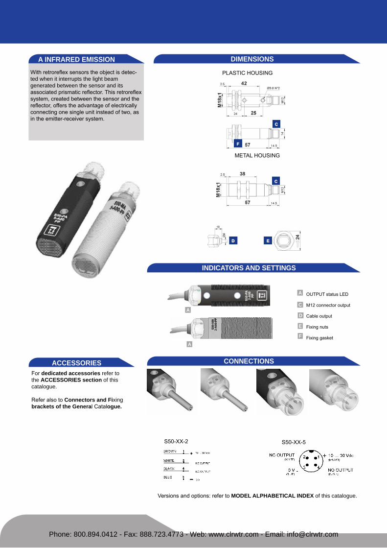
with retroreflex sensors the object is detec-ted when it interrupts the light beam generated between the sensor and itsassociated prismatic reflector. this retroreflex system, created between the sensor and the reflector, offers the advantage of electrically connecting one single unit instead of two, as in the emitter-receiver system.
DIMeNSIONS
PLastIc housIng
metaL housIng
INDICATORS AND SeTTINGS
s50-xx-2 s50-xx-5
CONNeCTIONSACCeSSORIeSfor dedicated accessories refer to the ACCeSSORIeS section of this catalogue.
refer also to Connectors and Fixing brackets of the General catalogue.
versions and options: refer to MODeL ALPHABeTICAL INDex of this catalogue.
A INFRAReD eMISSION
outPut status Led
m12 connector output
cable output
fixing nuts
fixing gasket
A
A
A
C
D
e
F
Phone: 800.894.0412 - Fax: 888.723.4773 - Web: www.clrwtr.com - Email: [email protected]

TeCHNICAL DATATeCHNICAL NOTeS1Limit values2 average life of 100.000 h with ta = +25 °c3 Pvc, 4 x 0.14 mm2
4 compatible with quick connection systems 5 a - reverse polarity protection b - overload and short-circuit protection on receiver outputs
S50-
PA-2
-A00
-NN
S50-
PA-2
-A00
-PP
S50-
PA-5
-A00
-NN
S50-
PA-5
-A00
-PP
S50-
MA
-2-A
00-N
N
S50-
MA
-2-A
00-P
P
S50-
MA
-5-A
00-N
N
S50-
MA
-5-A
00-P
P
Operating distance: 0.1 ... 5 m ● ● ● ● ● ● ● ●Power supply: 10 ... 30 vdc 1 ● ● ● ● ● ● ● ●
Ripple: ≤ 2 vpp ● ● ● ● ● ● ● ●Consumption: ≤ 35 ma ● ● ● ● ● ● ● ●
Light emission: infrared Led 880 nm 2 ● ● ● ● ● ● ● ●Spot dimension: approx. 100 mm at 2 m ● ● ● ● ● ● ● ●
Indicators: yellow outPut Led ● ● ● ● ● ● ● ●Output type: PnP, no and nc ● ● ● ●
nPn, no and nc ● ● ● ●Output current: ≤100 ma ● ● ● ● ● ● ● ●
Saturation voltage: ≤2 v ● ● ● ● ● ● ● ●Response time: 0.5 ms ● ● ● ● ● ● ● ●
Switching frequency: 1 khz ● ● ● ● ● ● ● ●Operating mode: dark on no / light on nc ● ● ● ● ● ● ● ●
Connection: 2 m Ø 4 mm cable 3 ● ● ● ●m12 4-pole connector 4 ● ● ● ●
electrical protection: class 2 ● ● ● ● ● ● ● ●Mechanical protection: IP67 ● ● ● ● ● ● ● ●
Protection devices: a, b 5 ● ● ● ● ● ● ● ●Housing material: Pbt ● ● ● ●
nickel plated brass ● ● ● ●Lens material: Pmma ● ● ● ● ● ● ● ●
Weight: 75 g max. ● ●25 g max. ● ●110 g max. ● ●60 g max. ● ●
Operating temperature: -25 ... +55°c ● ● ● ● ● ● ● ●Storage temperature: -25 ... +70°c ● ● ● ● ● ● ● ●Reference standard: en 60947-5-2 ● ● ● ● ● ● ● ●
SeLeCTION TABLe plastic - axial optics - 2 m cable
s50-Pa-2-a00-nn 952002090 nPn
s50-Pa-2-a00-PP 952002080 PnP
metal - axial optics - 2 m cable
s50-ma-2-a00-nn 952022090 nPn
s50-ma-2-a00-PP 952022080 PnP
plastic - axial optics - m12 connector
s50-Pa-5-a00-nn 952002110 nPn
s50-Pa-5-a00-PP 952002100 PnP
metal - axial optics - m12 connector
s50-ma-5-a00-nn 952022110 nPn
s50-ma-5-a00-PP 952022100 PnP
DeTeCTION DIAGRAMS
All the ordering codes and information are summarised in the last pages of this catalogue.
excess gain Detection area
r5
r2 r2r5
operating distance
II3dg
Phone: 800.894.0412 - Fax: 888.723.4773 - Web: www.clrwtr.com - Email: [email protected]

with retroreflex sensors the object is detec-ted when it interrupts the light beam genera-ted between the sensor and its associatedprismatic reflector. highpolarisation optic filters also allow reliable detection of very reflective objects, such as mirrored surfacesthat, differently from the prismatic reflector, reflect the light beam without rotating the polarisation plane.
DIMeNSIONSPLastIc housIng
metaL housIng
INDICATORS AND SeTTINGS
s50-xx-2 s50-xx-5
CONNeCTIONSACCeSSORIeSfor dedicated accessories refer to the ACCeSSORIeS section of this catalogue.
refer also to Reflectors (A.01), Con-nectors (A.03) and Fixing brackets (A.04) of the general catalogue.
versions and options: refer to MODeL ALPHABeTICAL INDex of this catalogue.
B INFRAReD eMISSION
A
A
A
C
B
D
B
B
e
outPut status and stability Leds
Adjustment trimmer
m12 connector output
cable output
fixing nuts
fixing gasketF
mm
radIaL oPtIcs
single-turn trimmer for sensitivity adjustment. rota-te in a clockwise direction to increase the operating distance.
Phone: 800.894.0412 - Fax: 888.723.4773 - Web: www.clrwtr.com - Email: [email protected]

plastic - axial optics - 2 m cable
s50-Pa-2-b01-nn 952001610 nPn
s50-Pa-2-b01-PP 952001010 PnP
metal - axial optics - 2 m cable
s50-ma-2-b01-nn 952021500 nPn
s50-ma-2-b01-PP 952021000 PnP
plastic - axial optics - m12 connector
s50-Pa-5-b01-nn 952001500 nPn
s50-Pa-5-b01-PP 952001020 PnP
metal - axial optics - m12 connector
s50-ma-5-b01-nn 952021660 nPn
s50-ma-5-b01-PP 952021200 PnP
plastic - radial optics - 2 m cable
s50-Pr-2-b01-nn 952001780 nPn
s50-Pr-2-b01-PP 952001030 PnP
metal - radial optics - 2 m cable
s50-mr-2-b01-nn 952021600 nPn
s50-mr-2-b01-PP 952021140 PnP
plastic - radial optics - m12 connector
s50-Pr-5-b01-nn 952001720 nPn
s50-Pr-5-b01-PP 952001040 PnP
metal - radial optics - m12 connector
s50-mr-5-b01-nn 952021760 nPn
s50-mr-5-b01-PP 952021340 PnP
TeCHNICAL NOTeS1Limit values2 average life of 100.000 h with tA = +25 °c3 270° single-turn trimmer4 Pvc, 4 x 0.14 mm2
5 compatible with quick connection systems 6 a - reverse polarity protection b - overload and short-circuit protection on receiver outputs
S50-
PA-2
-B01
-NN
S50-
PA-2
-B01
-PP
S50-
PA-5
-B01
-NN
S50-
PA-5
-B01
-PP
S50-
PR-2
-B01
-NN
S50-
PR-2
-B01
-PP
S50-
PR-5
-B01
-NN
S50-
PR-5
-B01
-PP
S50-
MA
-2-B
01-N
N
S50-
MA
-2-B
01-P
P
S50-
MA
-5-B
01-N
N
S50-
MA
-5-B
01-P
P
S50-
MR
-2-B
01-N
N
S50-
MR
-2-B
01-P
P
S50-
MR
-5-B
01-N
N
S50-
MR
-5-B
01-P
P
Operating distance:axial optics 0.1 ... 4.5 m ● ● ● ● ● ● ● ●radial optics 0.1 ... 3 m ● ● ● ● ● ● ● ●
Power supply: 10 ... 30 vdc 1 ● ● ● ● ● ● ● ● ● ● ● ● ● ● ● ●Ripple: ≤ 2 vpp ● ● ● ● ● ● ● ● ● ● ● ● ● ● ● ●
Consumption: ≤35 ma ● ● ● ● ● ● ● ● ● ● ● ● ● ● ● ●Light emission: red Led 660 nm2 ● ● ● ● ● ● ● ● ● ● ● ● ● ● ● ●Spot dimension:
axial optics approx. 45 mm at 1 m ● ● ● ● ● ● ● ●radial optics approx. 60 mm at 2 m ● ● ● ● ● ● ● ●
Setting: sensitivity trimmer 3 ● ● ● ● ● ● ● ● ● ● ● ● ● ● ● ●Indicators: yellow outPut Led ● ● ● ● ● ● ● ● ● ● ● ● ● ● ● ●
green stabILIty Led ● ● ● ● ● ● ● ● ● ● ● ● ● ● ● ●Output type: PnP, no and nc ● ● ● ● ● ● ● ●
nPn, no and nc ● ● ● ● ● ● ● ●Output current: ≤100 ma ● ● ● ● ● ● ● ● ● ● ● ● ● ● ● ●
Saturation voltage: ≤ 2 v ● ● ● ● ● ● ● ● ● ● ● ● ● ● ● ●Response time: 0.5 ms ● ● ● ● ● ● ● ● ● ● ● ● ● ● ● ●
Switching frequency: 1 khz ● ● ● ● ● ● ● ● ● ● ● ● ● ● ● ●Operating mode: dark on no / light on nc ● ● ● ● ● ● ● ● ● ● ● ● ● ● ● ●
Connection: 2 m Ø 4 mm cable4 ● ● ● ● ● ● ● ●m12 4-pole connector5 ● ● ● ● ● ● ● ●
electrical protection: class 2 ● ● ● ● ● ● ● ● ● ● ● ● ● ● ● ●Mechanical protection: IP67 ● ● ● ● ● ● ● ● ● ● ● ● ● ● ● ●
Protection devices: a, b6 ● ● ● ● ● ● ● ● ● ● ● ● ● ● ● ●Housing material: Pbt ● ● ● ● ● ● ● ●
nickel plated brass ● ● ● ● ● ● ● ●Lens material: Pmma ● ● ● ● ● ● ● ● ● ● ● ● ● ● ● ●
Weight: 75 g max. ● ● ● ●25 g max. ● ● ● ●110 g max. ● ● ● ●60 g max. ● ● ● ●
Operating temperature: -25 ... +55°c ● ● ● ● ● ● ● ● ● ● ● ● ● ● ● ●Storage temperature: -25 ... +70°c ● ● ● ● ● ● ● ● ● ● ● ● ● ● ● ●Reference standard: en 60947-5-2 ● ● ● ● ● ● ● ● ● ● ● ● ● ● ● ●
TeCHNICAL DATA SeLeCTION TABLe
DeTeCTION DIAGRAMS
excess gain - axial detection area - axial
excess gain - radial detection area - radial
All the ordering codes and information are summarised in the last pages of this catalogue.
recommended operating distancemaximum operating distance
high efficiency reflectors can be used to obtain larger operating distances.refer to Reflectors (a.01) of theGeneral Catalogue.
r2 r2
r2r2
r5
r5
r5r5
*only on axial optic models
II3dg*
Phone: 800.894.0412 - Fax: 888.723.4773 - Web: www.clrwtr.com - Email: [email protected]

The visible red laser emission increases the operating distance and resolution of the polarised retroreflex sensor. specific r7 or r8 reflectors with 0.8 mm microprisms are available for highresolution detection of smallobjects. the class 1 laser emission guarantees maximum safety for the operators in all applications.
DIMeNSIONSPLastIc housIng
metaL housIng
INDICATORS AND SeTTINGS
s50-xx-2 s50-xx-5
CONNeCTIONSACCeSSORIeSfor dedicated accessories refer to the ACCeSSORIeS section of this catalogue.
refer also to Reflectors (A.01), Con-nectors (A.03) and Fixing brackets (A.04) of the general catalogue.
versions and options: refer to MODeL ALPHABeTICAL INDex of this catalogue.
B LASeR ReD eMISSION
A
A
A
C
B
D
B
B
e
outPut status and stability Leds
Adjustment trimmer
m12 connector output
cable output
fixing nuts
fixing gasketF
mm
radIaL oPtIcs
single-turn trimmer for sensitivity adjustment. rota-te in a clockwise direction to increase the operating distance.
Phone: 800.894.0412 - Fax: 888.723.4773 - Web: www.clrwtr.com - Email: [email protected]

plastic - axial optics - 2 m cable
s50-PL-2-b01-nn 952001870 nPn
s50-PL-2-b01-PP 952001360 PnP
plastic - radial optics - 2 m cable
s50-Ph-2-b01-nn 952001950 nPn
s50-Ph-2-b01-PP 952001940 PnP
metal - axial optics - 2 m cable
s50-mL-2-b01-nn 952021820 nPn
s50-mL-2-b01-PP 952021400 PnP
metal - radial optics - 2 m cable
s50-mh-2-b01-nn 952021950 nPn
s50-mh-2-b01-PP 952021940 PnP
plastic -axial optics - m12 connector
s50-PL-5-b01-nn 952001840 nPn
s50-PL-5-b01-PP 952001370 PnP
plastic -radial optics - m12 connector
s50-Ph-5-b01-nn 952001970 nPn
s50-Ph-5-b01-PP 952001960 PnP
metal - axial optics - m12 connector
s50-mL-5-b01-nn 952021850 nPn
s50-mL-5-b01-PP 952021440 PnP
metal - radial optics - m12 connector
s50-mh-5-b01-nn 952021970 nPn
s50-mh-5-b01-PP 952021960 PnP
TeCHNICAL NOTeS1Limit values2 average life of 100.000 h with tA = +25 °c3 270° single-turn trimmer4 Pvc, 4 x 0.14 mm2
5 compatible with quick connection systems 6 a - reverse polarity protection b - overload and short-circuit protection on receiver outputs
S50-
PA-2
-B01
-NN
S50-
PA-2
-B01
-PP
S50-
PA-5
-B01
-NN
S50-
PA-5
-B01
-PP
S50-
PR-2
-B01
-NN
S50-
PR-2
-B01
-PP
S50-
PR-5
-B01
-NN
S50-
PR-5
-B01
-PP
S50-
MA
-2-B
01-N
N
S50-
MA
-2-B
01-P
P
S50-
MA
-5-B
01-N
N
S50-
MA
-5-B
01-P
P
S50-
MR
-2-B
01-N
N
S50-
MR
-2-B
01-P
P
S50-
MR
-5-B
01-N
N
S50-
MR
-5-B
01-P
P
Operating distance:axial optics 0.1 ... 16 m ● ● ● ● ● ● ● ●radial optics 0.1 ... 9 m ● ● ● ● ● ● ● ●
Power supply: 10 ... 30 vdc1 ● ● ● ● ● ● ● ● ● ● ● ● ● ● ● ●Ripple: ≤ 2 vpp ● ● ● ● ● ● ● ● ● ● ● ● ● ● ● ●
Consumption: ≤ 35 ma ● ● ● ● ● ● ● ● ● ● ● ● ● ● ● ●Light emission: red Laser 650 nm2 ● ● ● ● ● ● ● ● ● ● ● ● ● ● ● ●
class 1 en 60825-1class II cdrh21 cfr 1040.10
Resolution: 2 mm max. at 3 m (on r7) ● ● ● ● ● ● ● ● ● ● ● ● ● ● ● ●5 mm max. over 7 m (on r2) ● ● ● ● ● ● ● ● ● ● ● ● ● ● ● ●
Setting: sensitivity trimmer 3 ● ● ● ● ● ● ● ● ● ● ● ● ● ● ● ●Indicators: yellow outPut Led ● ● ● ● ● ● ● ● ● ● ● ● ● ● ● ●
green stabILIty Led ● ● ● ● ● ● ● ● ● ● ● ● ● ● ● ●Output type: PnP, no and nc ● ● ● ● ● ● ● ●
nPn, no and nc ● ● ● ● ● ● ● ●Output current: ≤ 100 ma ● ● ● ● ● ● ● ● ● ● ● ● ● ● ● ●
Saturation voltage: ≤ 2 v ● ● ● ● ● ● ● ● ● ● ● ● ● ● ● ●Response time: 333 ms ● ● ● ● ● ● ● ● ● ● ● ● ● ● ● ●
Switching frequency: 1.5 khz ● ● ● ● ● ● ● ● ● ● ● ● ● ● ● ●Operating mode: dark on no / light on nc ● ● ● ● ● ● ● ● ● ● ● ● ● ● ● ●
Connection: 2 m Ø 4 mm cable4 ● ● ● ● ● ● ● ●m12 4-pole connector5 ● ● ● ● ● ● ● ●
electrical protection: class 2 ● ● ● ● ● ● ● ● ● ● ● ● ● ● ● ●Mechanical protection: IP67 ● ● ● ● ● ● ● ● ● ● ● ● ● ● ● ●
Protection devices: a, b6 ● ● ● ● ● ● ● ● ● ● ● ● ● ● ● ●Housing material: Pbt ● ● ● ● ● ● ● ●
nickel plated brass ● ● ● ● ● ● ● ●Lens material: Pmma / glass ● ● ● ● ● ● ● ● ● ● ● ● ● ● ● ●
Weight: 75 g max. ● ● ● ● ● ● ● ●25 g max. ● ● ● ● ● ● ● ●110 g max. ● ● ● ●60 g max. ● ● ● ●
Operating temperature: -10 ... +50°c ● ● ● ● ● ● ● ● ● ● ● ● ● ● ● ●Storage temperature: -25 ... +70°c ● ● ● ● ● ● ● ● ● ● ● ● ● ● ● ●Reference standard: en 60947-5-2, en 60825-1, ● ● ● ● ● ● ● ● ● ● ● ● ● ● ● ●
cdrh21 cfr 1040.10 ● ● ● ● ● ● ● ● ● ● ● ● ● ● ● ●
TeCHNICAL DATA SeLeCTION TABLe
DeTeCTION DIAGRAMS
detection area - axial resolution on r7 reflector - axial
detection area - radial resolution on r7 reflector - radial
All the ordering codes and information are sum-marised in the last pages of this catalogue.
operating distance
high efficiency reflectors can be used to obtain larger operating distances.refer to Reflectors (a.01) of theGeneral Catalogue.
r7 r2
The use of the MICRO-18 fixing bracket (cod. 95ACC1380) is recommended for the correct optic axis alignment of the laser emission.
*only on axial optic models
II3dg*
Phone: 800.894.0412 - Fax: 888.723.4773 - Web: www.clrwtr.com - Email: [email protected]
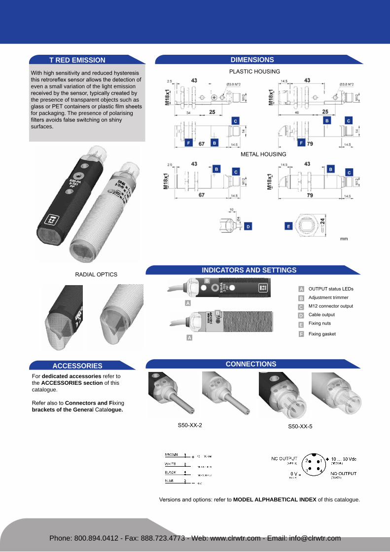
with high sensitivity and reduced hysteresis this retroreflex sensor allows the detection of even a small variation of the light emission received by the sensor, typically created by the presence of transparent objects such asglass or Pet containers or plastic film sheets for packaging. The presence of polarising filters avoids false switching on shinysurfaces.
DIMeNSIONSPLastIc housIng
metaL housIng
INDICATORS AND SeTTINGS
s50-xx-2 s50-xx-5
CONNeCTIONSACCeSSORIeSfor dedicated accessories refer to the ACCeSSORIeS section of this catalogue.
refer also to Connectors and Fixing brackets of the General catalogue.
versions and options: refer to MODeL ALPHABeTICAL INDex of this catalogue.
T ReD eMISSION
A
A
A
C
B
D
B
B
e
outPut status Leds
Adjustment trimmer
m12 connector output
cable output
fixing nuts
fixing gasketF
mm
radIaL oPtIcs
Phone: 800.894.0412 - Fax: 888.723.4773 - Web: www.clrwtr.com - Email: [email protected]

plastic - axial optics - 2 m cable
s50-Pa-2-t01-nn 952001690 nPn
s50-Pa-2-t01-PP 952001260 PnP
metal - axial optics - 2 m cable
s50-ma-2-t01-nn 952021570 nPn
s50-ma-2-t01-PP 952021090 PnP
plastic - axial optics - m12 connector
s50-Pa-5-t01-nn 952001580 nPn
s50-Pa-5-t01-PP 952001270 PnP
metal - axial optics - m12 connector
s50-ma-5-t01-nn 952021730 nPn
s50-ma-5-t01-PP 952021290 PnP
plastic - radial optics - 2 m cable
s50-Pr-2-t01-nn 952001830 nPn
s50-Pr-2-t01-PP 952001280 PnP
metal - radial optics - 2 m cable
s50-mr-2-t01-nn 952021650 nPn
s50-mr-2-t01-PP 952021190 PnP
plastic - radial optics - m12 connector
s50-Pr-5-t01-nn 952001770 nPn
s50-Pr-5-t01-PP 952001290 PnP
metal - radial optics - m12 connector
s50-mr-5-t01-nn 952021810 nPn
s50-mr-5-t01-PP 952021390 PnP
TeCHNICAL DATA SeLeCTION TABLe
DeTeCTION DIAGRAMS
excess gain Detection area
r5
r2
r2 r5
recommended operating distancemaximum operating distance
high efficiency reflectors can be used to obtain larger operating distances.refer to Reflectors of theGeneral Catalogue.
All the ordering codes and information are sum-marised in the last pages of this catalogue.
TeCHNICAL NOTeS1Limit values2 average life of 100.000 h with tA = +25 °c3 270° single-turn trimmer4 Pvc, 4 x 0.14 mm2
5 compatible with quick connection systems 6 a - reverse polarity protection b - overload and short-circuit protection on receiver outputs
S50-
PA-2
-T01
-NN
S50-
PA-2
-T01
-PP
S50-
PA-5
-T01
-NN
S50-
PA-5
-T01
-PP
S50-
PR-2
-T01
-NN
S50-
PR-2
-T01
-PP
S50-
PR-5
-T01
-NN
S50-
PR-5
-T01
-PP
S50-
MA
-2-T
01-N
N
S50-
MA
-2-T
01-P
P
S50-
MA
-5-T
01-N
N
S50-
MA
-5-T
01-P
P
S50-
MR
-2-T
01-N
N
S50-
MR
-2-T
01-P
P
S50-
MR
-5-T
01-N
N
S50-
MR
-5-T
01-P
P
Operating distance:axial optics 0.1 ... 1.7 m ● ● ● ● ● ● ● ●radial optics 0.1 ... 1.7 m ● ● ● ● ● ● ● ●
Power supply: 10 ... 30 vdc 1 ● ● ● ● ● ● ● ● ● ● ● ● ● ● ● ●Ripple: ≤ 2 vpp ● ● ● ● ● ● ● ● ● ● ● ● ● ● ● ●
Consumption: ≤ 35 ma ● ● ● ● ● ● ● ● ● ● ● ● ● ● ● ●Light emission: red Led 660 nm 2 ● ● ● ● ● ● ● ● ● ● ● ● ● ● ● ●Spot dimension:
axial optics approx. 45 mm at 1 m ● ● ● ● ● ● ● ●radial optics approx. 60 mm at 1 m ● ● ● ● ● ● ● ●
Setting: sensitivity trimmer 3 ● ● ● ● ● ● ● ● ● ● ● ● ● ● ● ●Indicators: yellow outPut Led ● ● ● ● ● ● ● ● ● ● ● ● ● ● ● ●
Output type: PnP, no and nc ● ● ● ● ● ● ● ●nPn, no and nc ● ● ● ● ● ● ● ●
Output current: ≤ 100 ma ● ● ● ● ● ● ● ● ● ● ● ● ● ● ● ●Saturation voltage: ≤ 2 v ● ● ● ● ● ● ● ● ● ● ● ● ● ● ● ●
Response time: 0.5 ms ● ● ● ● ● ● ● ● ● ● ● ● ● ● ● ●Switching frequency: 1 khz ● ● ● ● ● ● ● ● ● ● ● ● ● ● ● ●
Operating mode: dark on no / light on nc ● ● ● ● ● ● ● ● ● ● ● ● ● ● ● ●Connection: 2 m Ø 4 mm cable 4 ● ● ● ● ● ● ● ●
m12 4-pole connector 5 ● ● ● ● ● ● ● ●electrical protection: class 2 ● ● ● ● ● ● ● ● ● ● ● ● ● ● ● ●
Mechanical protection: IP67 ● ● ● ● ● ● ● ● ● ● ● ● ● ● ● ●Protection devices: a, b 6 ● ● ● ● ● ● ● ● ● ● ● ● ● ● ● ●Housing material: Pbt ● ● ● ● ● ● ● ●
nickel plated brass ● ● ● ● ● ● ● ●Lens material: Pmma ● ● ● ● ● ● ● ● ● ● ● ● ● ● ● ●
Weight: 75 g max. ● ● ● ●25 g max. ● ● ● ●110 g max. ● ● ● ●60 g max. ● ● ● ●
Operating temperature: -25 ... +55°c ● ● ● ● ● ● ● ● ● ● ● ● ● ● ● ●Storage temperature: -25 ... +70°c ● ● ● ● ● ● ● ● ● ● ● ● ● ● ● ●Reference standard: en 60947-5-2 ● ● ● ● ● ● ● ● ● ● ● ● ● ● ● ●
*only on axial optic models
II3dg*
Phone: 800.894.0412 - Fax: 888.723.4773 - Web: www.clrwtr.com - Email: [email protected]

This diffuse proximity sensor represents a reliable, simple and cost-effective solution for the direct detection of any object inside the fixed operating distance. Its particularly compact dimensions permit the installation in very small spaces.
DIMeNSIONSPLastIc housIng
metaL housIng
INDICATORS AND SeTTINGS
s50-xx-2 s50-xx-5
CONNeCTIONSACCeSSORIeSfor dedicated accessories refer to the ACCeSSORIeS section of this catalogue.
refer also to Connectors and Fixing brackets of the General catalogue.
versions and options: refer to MODeL ALPHABeTICAL INDex of this catalogue.
C SHORT INFRAReD eMISSION
A
A
A
CD
e
outPut status Leds
m12 connector output
cable output
fixing nuts
fixing gasketF
mm
radIaL oPtIcs
Phone: 800.894.0412 - Fax: 888.723.4773 - Web: www.clrwtr.com - Email: [email protected]

plastic - axial optics - 2 m cable
s50-Pa-2-c10-nn 952001630 nPn
s50-Pa-2-c10-PP 952001240 PnP
metal - axial optics - 2 m cable
s50-ma-2-c10-nn 952021520 nPn
s50-ma-2-c10-PP 952021020 PnP
plastic - axial optics - m12 connector
s50-Pa-5-c10-nn 952001520 nPn
s50-Pa-5-c10-PP 952001250 PnP
metal - axial optics - m12 connector
s50-ma-5-c10-nn 952021680 nPn
s50-ma-5-c10-PP 952021220 PnP
plastic - radial optics - 2 m cable
s50-Pr-2-c10-nn 952001800 nPn
s50-Pr-2-c10-PP 952001490 PnP
metal - radial optics - 2 m cable
s50-mr-2-c10-nn 952021620 nPn
s50-mr-2-c10-PP 952021490 PnP
plastic - radial optics - m12 connector
s50-Pr-5-c10-nn 952001740 nPn
s50-Pr-5-c10-PP 952001480 PnP
metal - radial optics - m12 connector
s50-mr-5-c10-nn 952021780 nPn
s50-mr-5-c10-PP 952021480 PnP
TeCHNICAL NOTeS1Limit values2 average life of 100.000 h with tA = +25 °c3 Pvc, 4 x 0.14 mm2
4 compatible with quick connection systems 5 a - reverse polarity protection b - overload and short-circuit protection on receiver outputs
S50-
PA-2
-C10
-NN
S50-
PA-2
-C10
-PP
S50-
PA-5
-C10
-NN
S50-
PA-5
-C10
-PP
S50-
PR-2
-C10
-NN
S50-
PR-2
-C10
-PP
S50-
PR-5
-C10
-NN
S50-
PR-5
-C10
-PP
S50-
MA
-2-C
10-N
N
S50-
MA
-2-C
10-P
P
S50-
MA
-5-C
10-N
N
S50-
MA
-5-C
10-P
P
S50-
MR
-2-C
10-N
N
S50-
MR
-2-C
10-P
P
S50-
MR
-5-C
10-N
N
S50-
MR
-5-C
10-P
Px
Operating distance:axial optics 0 ... 10 cm ● ● ● ● ● ● ● ●radial optics 0 ... 8 cm ● ● ● ● ● ● ● ●
Power supply: 10 ... 30 vdc 1 ● ● ● ● ● ● ● ● ● ● ● ● ● ● ● ●Ripple: ≤ 2 vpp ● ● ● ● ● ● ● ● ● ● ● ● ● ● ● ●
Consumption: ≤ 35 ma ● ● ● ● ● ● ● ● ● ● ● ● ● ● ● ●Light emission: infrared Led 880 nm2 ● ● ● ● ● ● ● ● ● ● ● ● ● ● ● ●Spot dimension:
axial optics approx. 80 mm at 10 cm ● ● ● ● ● ● ● ●radial optics approx. 55 mm at 10 cm ● ● ● ● ● ● ● ●Indicators: yellow outPut Led ● ● ● ● ● ● ● ● ● ● ● ● ● ● ● ●
Output type: PnP, no and nc ● ● ● ● ● ● ● ●nPn, no and nc ● ● ● ● ● ● ● ● ●
output current: ≤ 100 ma ● ● ● ● ● ● ● ● ● ● ● ● ● ● ● ●Saturation voltage: ≤ 2 v ● ● ● ● ● ● ● ● ● ● ● ● ● ● ● ●
Response time: 0.5 ms ● ● ● ● ● ● ● ● ● ● ● ● ● ● ● ●Switching frequency: 1 khz ● ● ● ● ● ● ● ● ● ● ● ● ● ● ● ●
Operating mode: dark on no / light on nc ● ● ● ● ● ● ● ● ● ● ● ● ● ● ● ●Connection: 2 m Ø 4 mm cable3 ● ● ● ● ● ● ● ●
m12 4-pole connector4 ● ● ● ● ● ● ● ●electrical protection: class 2 ● ● ● ● ● ● ● ● ● ● ● ● ● ● ● ●
Mechanical protection: IP67 ● ● ● ● ● ● ● ● ● ● ● ● ● ● ● ●Protection devices: a, b5 ● ● ● ● ● ● ● ● ● ● ● ● ● ● ● ●Housing material: Pbt ● ● ● ● ● ● ● ●
nickel plated brass ● ● ● ● ● ● ● ●Lens material: Pmma ● ● ● ● ● ● ● ● ● ● ● ● ● ● ● ●
Weight: 75 g max. ● ● ● ● ● ● ● ● ● ● ● ●25 g max. ● ● ● ●110 g max. ● ● ● ●60 g max. ● ● ● ●
Operating temperature: -25 ... +55°c ● ● ● ● ● ● ● ● ● ● ● ● ● ● ● ●Storage temperature: -25 ... +70°c ● ● ● ● ● ● ● ● ● ● ● ● ● ● ● ●Reference standard: en 60947-5-2 ● ● ● ● ● ● ● ● ● ● ● ● ● ● ● ●
TeCHNICAL DATA SeLeCTION TABLe
DeTeCTION DIAGRAMS
excess gain - axial detection area - axial
excess gain - radial detection area - radial
grey 18% grey 18%
grey 18%
white 90%
white 90%
white 90%
recommended operating distancemaximum operating distance
All the ordering codes and information are summarised in the last pages of this catalogue.
grey 18%
white 90%
*only on axial optic models
II3dg*
Phone: 800.894.0412 - Fax: 888.723.4773 - Web: www.clrwtr.com - Email: [email protected]
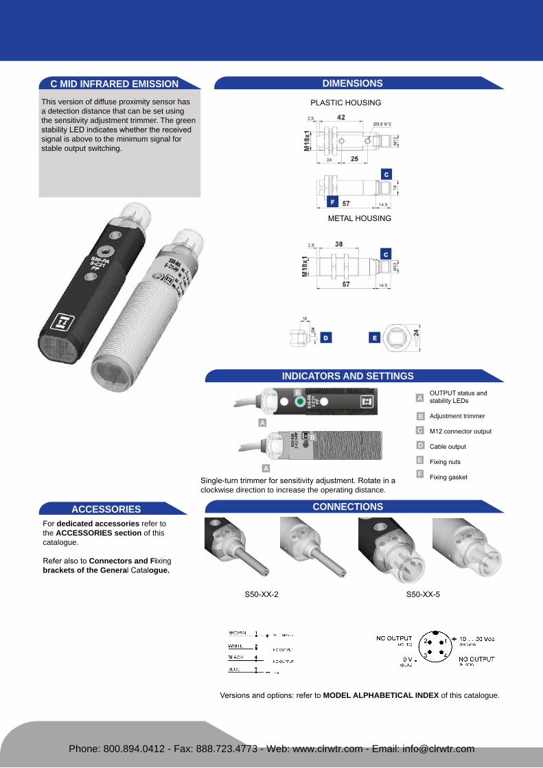
This version of diffuse proximity sensor has a detection distance that can be set using the sensitivity adjustment trimmer. The green stability Led indicates whether the received signal is above to the minimum signal for stable output switching.
DIMeNSIONS
PLastIc housIng
metaL housIng
INDICATORS AND SeTTINGS
s50-xx-2 s50-xx-5
CONNeCTIONSACCeSSORIeSfor dedicated accessories refer to the ACCeSSORIeS section of this catalogue.
refer also to Connectors and Fixing brackets of the General catalogue.
versions and options: refer to MODeL ALPHABeTICAL INDex of this catalogue.
C MID INFRAReD eMISSION
outPut status and stability Leds
Adjustment trimmer
m12 connector output
cable output
fixing nuts
fixing gasket
A
A
A
C
D
e
Fsingle-turn trimmer for sensitivity adjustment. rotate in aclockwise direction to increase the operating distance.
B
B
B
Phone: 800.894.0412 - Fax: 888.723.4773 - Web: www.clrwtr.com - Email: [email protected]

TeCHNICAL DATATeCHNICAL NOTeS1Limit values2 average life of 100.000 h with ta = +25 °c3 270° single-turn trimmer4 Pvc, 4 x 0.14 mm2
5 compatible with quick connection systems 6 a - reverse polarity protection b - overload and short-circuit protection on receiver outputs
S50-
PA-2
-C21
-NN
S50-
PA-2
-C21
-PP
S50-
PA-5
-C21
-NN
S50-
PA-5
-C21
-PP
S50-
MA
-2-C
21-N
N
S50-
MA
-2-C
21-P
P
S50-
MA
-5-C
21-N
N
S50-
MA
-5-C
21-P
P
Operating distance: 0 ... 40 cm ● ● ● ● ● ● ● ●Power supply: 10 ... 30 vdc 1 ● ● ● ● ● ● ● ●
Ripple: ≤ 2 vpp ● ● ● ● ● ● ● ●Consumption: ≤ 35 ma ● ● ● ● ● ● ● ●
Light emission: infrared Led 880 nm2 ● ● ● ● ● ● ● ●Spot dimension: approx. 100 mm at 300 cm ● ● ● ● ● ● ● ●
Setting: sensitivity trimmer 3 ● ● ● ● ● ● ● ●Indicators: yellow outPut Led ● ● ● ● ● ● ● ●
green stabILIty Led ● ● ● ● ● ● ● ●Output type: PnP, no and nc ● ● ● ●
nPn, no and nc ● ● ● ●Output current: ≤ 100 ma ● ● ● ● ● ● ● ●
Saturation voltage: ≤ 2 v ● ● ● ● ● ● ● ●Response time: 0.5 ms ● ● ● ● ● ● ● ●
Switching frequency: 1 khz ● ● ● ● ● ● ● ●Operating mode: light on no / dark on nc ● ● ● ● ● ● ● ●
Connection: 2 m Ø 4 mm cable4 ● ● ● ●m12 4-pole connector5 ● ● ● ●
electrical protection: class 2 ● ● ● ● ● ● ● ●Mechanical protection: IP67 ● ● ● ● ● ● ● ●
Protection devices: a, b6 ● ● ● ● ● ● ● ●Housing material: Pbt ● ● ● ●
nickel plated brass ● ● ● ●Lens material: Pmma ● ● ● ● ● ● ● ●
Weight: 75 g max. ● ●25 g max. ● ●110 g max. ● ●60 g max. ● ●
Operating temperature: -25 ... +55°c ● ● ● ● ● ● ● ●Storage temperature: -25 ... +70°c ● ● ● ● ● ● ● ●Reference standard: en 60947-5-2 ● ● ● ● ● ● ● ●
SeLeCTION TABLe plastic - axial optics - 2 m cable
s50-Pa-2-c21-nn 952002170 nPn
s50-Pa-2-c21-PP 952002160 PnP
metal - axial optics - 2 m cable
s50-ma-2-c21-nn 952022130 nPn
s50-ma-2-c21-PP 952022120 PnP
plastic - axial optics - m12 connector
s50-Pa-5-c21-nn 952002190 nPn
s50-Pa-5-c21-PP 952002180 PnP
metal - axial optics - m12 connector
s50-ma-5-c21-nn 952022150 nPn
s50-ma-5-c21-PP 952022140 PnP
DeTeCTION DIAGRAMS
All the ordering codes and information are summarised in the last pages of this catalogue.
excess gain Detection area
grey 18% grey 18%
white 90%
white 90%
recommended operating distancemaximum operating distance
II3dg
Phone: 800.894.0412 - Fax: 888.723.4773 - Web: www.clrwtr.com - Email: [email protected]
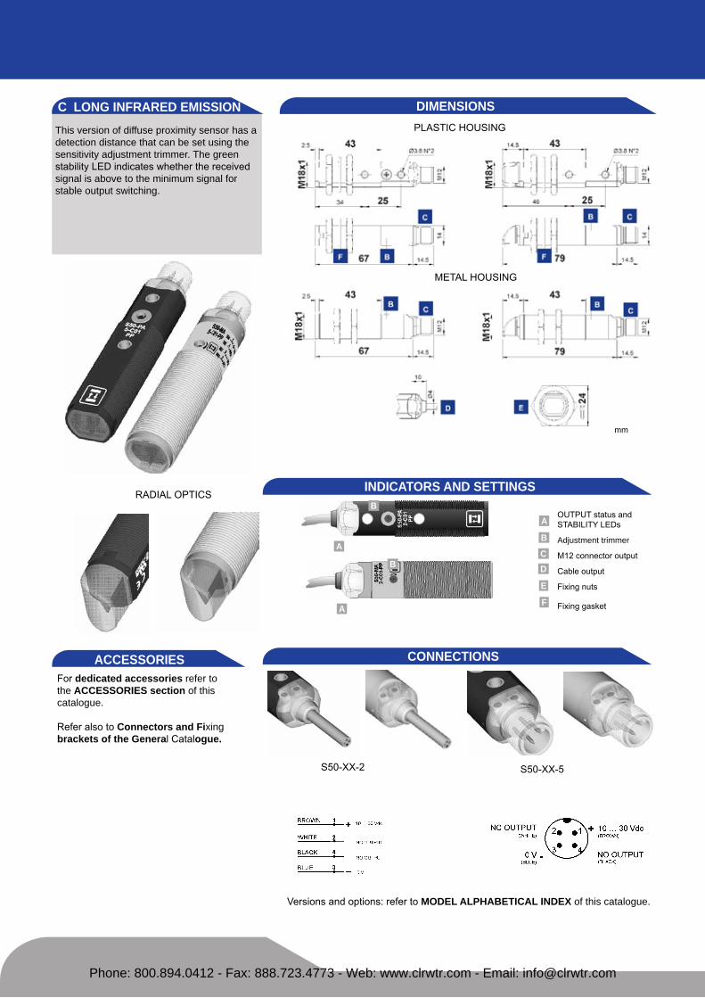
This version of diffuse proximity sensor has a detection distance that can be set using thesensitivity adjustment trimmer. The green stability Led indicates whether the received signal is above to the minimum signal forstable output switching.
DIMeNSIONSPLastIc housIng
metaL housIng
INDICATORS AND SeTTINGS
s50-xx-2 s50-xx-5
CONNeCTIONSACCeSSORIeSfor dedicated accessories refer to the ACCeSSORIeS section of this catalogue.
refer also to Connectors and Fixing brackets of the General catalogue.
versions and options: refer to MODeL ALPHABeTICAL INDex of this catalogue.
C LONG INFRAReD eMISSION
A
A
A
C
B
D
B
B
e
outPut status and stabILIty Leds
Adjustment trimmer
m12 connector output
cable output
fixing nuts
fixing gasketF
mm
radIaL oPtIcs
Phone: 800.894.0412 - Fax: 888.723.4773 - Web: www.clrwtr.com - Email: [email protected]

plastic - axial optics - 2 m cable
s50-Pa-2-c01-nn 952001620 nPn
s50-Pa-2-c01-PP 952001050 PnP
metal - axial optics - 2 m cable
s50-ma-2-c01-nn 952021510 nPn
s50-ma-2-c01-PP 952021010 PnP
plastic - axial optics - m12 connector
s50-Pa-5-c01-nn 952001510 nPn
s50-Pa-5-c01-PP 952001060 PnP
metal - axial optics - m12 connector
s50-ma-5-c01-nn 952021670 nPn
s50-ma-5-c01-PP 952021210 PnP
plastic - radial optics - 2 m cable
s50-Pr-2-c01-nn 952001790 nPn
s50-Pr-2-c01-PP 952001070 PnP
metal - radial optics - 2 m cable
s50-mr-2-c01-nn 952021610 nPn
s50-mr-2-c01-PP 952021150 PnP
plastic - radial optics - m12 connector
s50-Pr-5-c01-nn 952001730 nPn
s50-Pr-5-c01-PP 952001080 PnP
metal - radial optics - m12 connector
s50-mr-5-c01-nn 952021770 nPn
s50-mr-5-c01-PP 952021350 PnP
TeCHNICAL NOTeS1Limit values2 average life of 100.000 h with tA = +25 °c3 270° single-turn trimmer4 Pvc, 4 x 0.14 mm2
5 compatible with quick connection systems 6 a - reverse polarity protection b - overload and short-circuit protection on receiver outputs
S50-
PA-2
-C01
-NN
S50-
PA-2
-C01
-PP
S50-
PA-5
-C01
-NN
S50-
PA-5
-C01
-PP
S50-
PR-2
-C01
-NN
S50-
PR-2
-C01
-PP
S50-
PR-5
-C01
-NN
S50-
PR-5
-C01
-PP
S50-
MA
-2-C
01-N
N
S50-
MA
-2-C
01-P
P
S50-
MA
-5-C
01-N
N
S50-
MA
-5-C
01-P
P
S50-
MR
-2-C
01-N
N
S50-
MR
-2-C
01-P
P
S50-
MR
-5-C
01-N
N
S50-
MR
-5-C
01-P
P
Operating distance:axial optics 0 ... 70 cm ● ● ● ● ● ● ● ●radial optics 0 ... 40 cm ● ● ● ● ● ● ● ●
Power supply: 10 ... 30 vdc 1 ● ● ● ● ● ● ● ● ● ● ● ● ● ● ● ●Ripple: ≤2 vpp ● ● ● ● ● ● ● ● ● ● ● ● ● ● ● ●
Consumption: ≤ 35 ma ● ● ● ● ● ● ● ● ● ● ● ● ● ● ● ●Light emission: infrared Led 880 nm 2 ● ● ● ● ● ● ● ● ● ● ● ● ● ● ● ●Spot dimension:
axial optics approx.200 mm at 60 cm ● ● ● ● ● ● ● ●radial optics approx.35 mm at 40 cm ● ● ● ● ● ● ● ●
Setting: sensitivity trimmer 3 ● ● ● ● ● ● ● ● ● ● ● ● ● ● ● ●Indicators: yellow outPut Led ● ● ● ● ● ● ● ● ● ● ● ● ● ● ● ●
green stabILIty Led ● ● ● ● ● ● ● ● ● ● ● ● ● ● ● ●output type: PnP, no and nc ● ● ● ● ● ● ● ●
nPn, no and nc ● ● ● ● ● ● ● ●Output current: ≤ 100 ma ● ● ● ● ● ● ● ● ● ● ● ● ● ● ● ●
Saturation voltage: ≤ 2 v ● ● ● ● ● ● ● ● ● ● ● ● ● ● ● ●Response time: 0.5 ms ● ● ● ● ● ● ● ● ● ● ● ● ● ● ● ●
Switching frequency: 1 khz ● ● ● ● ● ● ● ● ● ● ● ● ● ● ● ●Operating mode: dark on no / light on nc ● ● ● ● ● ● ● ● ● ● ● ● ● ● ● ●
Connection: 2 m Ø 4 mm cable4 ● ● ● ● ● ● ● ●m12 4-pole connector5 ● ● ● ● ● ● ● ●
electrical protection: class 2 ● ● ● ● ● ● ● ● ● ● ● ● ● ● ● ●Mechanical protection: IP67 ● ● ● ● ● ● ● ● ● ● ● ● ● ● ● ●
Protection devices: a, b6 ● ● ● ● ● ● ● ● ● ● ● ● ● ● ● ●Housing material: Pbt ● ● ● ● ● ● ● ●
nickel plated brass ● ● ● ● ● ● ● ●Lens material: Pmma ● ● ● ● ● ● ● ● ● ● ● ● ● ● ● ●
Weight: 75 g max. ● ● ● ●25 g max. ● ● ● ●110 g max. ● ● ● ●60 g max. ● ● ● ●
Operating temperature: -25 ... +55°c ● ● ● ● ● ● ● ● ● ● ● ● ● ● ● ●Storage temperature: -25 ... +70°c ● ● ● ● ● ● ● ● ● ● ● ● ● ● ● ●
Reference standard: en 60947-5-2 ● ● ● ● ● ● ● ● ● ● ● ● ● ● ● ●
TeCHNICAL DATA SeLeCTION TABLe
All the ordering codes and information are summarised in the last pages of this catalogue.
DeTeCTION DIAGRAMS
excess gain - axial detection area - axial
excess gain - radial detection area - radial
grey 18% grey 18%
grey 18%
white 90%
white 90%
white 90%grey 18%
white 90%recommended operating distancemaximum operating distance
*only on axial optic models
II3dg*
Phone: 800.894.0412 - Fax: 888.723.4773 - Web: www.clrwtr.com - Email: [email protected]

the fixed focus proximity sensor offers a sim-ple fixed background suppression distance beyond which no object is detected. the fixed triangulation of the optics greatly reduces the detection distance of reflective objects. thevisible red emission facilitates sensor instal-lation.
DIMeNSIONSPLastIc housIng
metaL housIng
INDICATORS AND SeTTINGS
s50-xx-2 s50-xx-5
CONNeCTIONSACCeSSORIeSfor dedicated accessories refer to the ACCeSSORIeS section of this catalogue.
refer also to Connectors and Fixing brackets of the General catalogue.
versions and options: refer to MODeL ALPHABeTICAL INDex of this catalogue.
D ReD eMISSION
A
A
A
CD
e
outPut status Led
m12 connector output
cable output
fixing nuts
fixing gasketF
mm
radIaL oPtIcs
Phone: 800.894.0412 - Fax: 888.723.4773 - Web: www.clrwtr.com - Email: [email protected]

plastic - axial optics - 2 m cable
s50-Pa-2-d00-nn 952001640 nPn
s50-Pa-2-d00-PP 952001090 PnP
metal - axial optics - 2 m cable
s50-ma-2-d00-nn 952021530 nPn
s50-ma-2-d00-PP 952021030 PnP
plastic - axial optics - m12 connector
s50-Pa-5-d00-nn 952001530 nPn
s50-Pa-5-d00-PP 952001100 PnP
metal - axial optics - m12 connector
s50-ma-5-d00-nn 952021690 nPn
s50-ma-5-d00-PP 952021230 PnP
plastic - radial optics - 2 m cable
s50-Pr-2-d00-nn 952001810 nPn
s50-Pr-2-d00-PP 952001110 PnP
metal - radial optics - 2 m cable
s50-mr-2-d00-nn 952021630 nPn
s50-mr-2-d00-PP 952021160 PnP
plastic - radial optics - m12 connector
s50-Pr-5-d00-nn 952001750 nPn
s50-Pr-5-d00-PP 952001120 PnP
metal - radial optics - m12 connector
s50-mr-5-d00-nn 952021790 nPn
s50-mr-5-d00-PP 952021360 PnP
TeCHNICAL NOTeS1Limit values2 average life of 100.000 h with tA = +25 °c3 Pvc, 4 x 0.14 mm2
4 compatible with quick connection systems 5 a - reverse polarity protection b - overload and short-circuit protection on receiver outputs
S50-
PA-2
-D00
-NN
S50-
PA-2
-D00
-PP
S50-
PA-5
-D00
-NN
S50-
PA-5
-D00
-PP
S50-
PR-2
-D00
-NN
S50-
PR-2
-D00
-PP
S50-
PR-5
-D00
-NN
S50-
PR-5
-D00
-PP
S50-
MA
-2-D
00-N
N
S50-
MA
-2-D
00-P
P
S50-
MA
-5-D
00-N
N
S50-
MA
-5-D
00-P
P
S50-
MR
-2-D
00-N
N
S50-
MR
-2-D
00-P
P
S50-
MR
-5-D
00-N
N
S50-
MR
-5-D
00-P
P
Operating distance:axial optics 0.5 ... 10 cm ● ● ● ● ● ● ● ●radial optics 0 ... 8 cm ● ● ● ● ● ● ● ●
Power supply: 10 ... 30 vdc 1 ● ● ● ● ● ● ● ● ● ● ● ● ● ● ● ●Ripple: ≤ 2 vpp ● ● ● ● ● ● ● ● ● ● ● ● ● ● ● ●
Consumption: ≤ 35 ma ● ● ● ● ● ● ● ● ● ● ● ● ● ● ● ●Light emission: red Led 630 nm2 ● ● ● ● ● ● ● ● ● ● ● ● ● ● ● ●Spot dimension:
axial optics approx. 20 mm at 10 cm ● ● ● ● ● ● ● ●radial optics approx. 25 mm at 8 cm ● ● ● ● ● ● ● ●Indicators: yellow outPut Led ● ● ● ● ● ● ● ● ● ● ● ● ● ● ● ●
Output type: PnP, no and nc ● ● ● ● ● ● ● ●nPn, no and nc ● ● ● ● ● ● ● ●
output current: ≤ 100 ma ● ● ● ● ● ● ● ● ● ● ● ● ● ● ● ●Saturation voltage: ≤ 2 v ● ● ● ● ● ● ● ● ● ● ● ● ● ● ● ●
Response time: 0.5 ms ● ● ● ● ● ● ● ● ● ● ● ● ● ● ● ●Switching frequency: 1 khz ● ● ● ● ● ● ● ● ● ● ● ● ● ● ● ●
Operating mode: dark on no / light on nc ● ● ● ● ● ● ● ● ● ● ● ● ● ● ● ●Connection: 2 m Ø 4 mm cable ● ● ● ● ● ● ● ●
m12 4-pole connector ● ● ● ● ● ● ● ●electrical protection: class 2 ● ● ● ● ● ● ● ● ● ● ● ● ● ● ● ●
Mechanical protection: IP67 ● ● ● ● ● ● ● ● ● ● ● ● ● ● ● ●Protection devices: a, b5 ● ● ● ● ● ● ● ● ● ● ● ● ● ● ● ●Housing material: Pbt ● ● ● ● ● ● ● ●
nickel plated brass ● ● ● ● ● ● ● ●Lens material: Pmma ● ● ● ● ● ● ● ● ● ● ● ● ● ● ● ●
Weight: 75 g max. ● ● ● ●25 g max. ● ● ● ●110 g max. ● ● ● ●60 g max. ● ● ● ●
Operating temperature: -25 ... +55°c ● ● ● ● ● ● ● ● ● ● ● ● ● ● ● ●Storage temperature: -25 ... +70°c ● ● ● ● ● ● ● ● ● ● ● ● ● ● ● ●Reference standard: en 60947-5-2 ● ● ● ● ● ● ● ● ● ● ● ● ● ● ● ●
TeCHNICAL DATA SeLeCTION TABLe
All the ordering codes and information are summarised in the last pages of this catalogue.
DeTeCTION DIAGRAMS
excess gain - axial detection area - axial
excess gain - radial detection area - radial
grey 18% grey 18%
grey 18%
white 90%
white 90%
white 90%grey 18%
white 90%
operating distance
*only on axial optic models
II3dg*
Phone: 800.894.0412 - Fax: 888.723.4773 - Web: www.clrwtr.com - Email: [email protected]

The visible red laser emission allows the accurate detection of very small objects. The sensors operate as a proximity device up to35 cm and can be used as a contrast sensor for high contrast mark detection. the class 1 laser emission guarantees maximumsafety for the operators in all applications.
DIMeNSIONSPLastIc housIng
metaL housIng
INDICATORS AND SeTTINGS
s50-xx-2 s50-xx-5
CONNeCTIONSACCeSSORIeSfor dedicated accessories refer to the ACCeSSORIeS section of this catalogue.
refer also to Connectors and Fixing brackets of the General catalogue.
versions and options: refer to MODeL ALPHABeTICAL INDex of this catalogue.
C LASeR ReD eMISSION
mm
radIaL oPtIcs
A
A
B
B
A
C
B
D
e
outPut status and stability Leds
Adjustment trimmer
m12 connector output
cable output
fixing nuts
fixing gasketF
single-turn trimmer for sensitivity adjustment. rotate in aclockwise direction to increase the operating distance.
Phone: 800.894.0412 - Fax: 888.723.4773 - Web: www.clrwtr.com - Email: [email protected]

plastic - axial optics - 2 m cable
s50-PL-2-c01-nn 952001880 nPn
s50-PL-2-c01-PP 952001380 PnP
plastic - radial optics - 2 m cable
s50-Ph-2-c01-nn 952001990 nPn
s50-Ph-2-c01-PP 952001980 PnP
metal - axial optics - 2 m cable
s50-mL-2-c01-nn 952021830 nPn
s50-mL-2-c01-PP 952021410 PnP
metal - radial optics - 2 m cable
s50-mh-2-c01-nn 952021990 nPn
s50-mh-2-c01-PP 952021980 PnP
plastic - axial optics - m12 connector
s50-PL-5-c01-nn 952001850 nPn
s50-PL-5-c01-PP 952001390 PnP
plastic - radial optics - m12 connector
s50-Ph-5-c01-nn 952002010 nPn
s50-Ph-5-c01-PP 952002000 PnP
metal - axial optics - m12 connector
s50-mL-5-c01-nn 952021860 nPn
s50-mL-5-c01-PP 952021450 PnP
metal - radial optics - m12 connector
s50-mh-5-c01-nn 952022010 nPn
s50-mh-5-c01-PP 952022000 PnP
TeCHNICAL NOTeS1Limit values2 average life of 100.000 h with tA = +25 °c3 270° single-turn trimmer4 Pvc, 4 x 0.14 mm2
5 compatible with quick connection systems 6 a - reverse polarity protection b - overload and short-circuit protection on receiver outputs
S50-
PL-2
-C01
-NN
S50-
PL-2
-C01
-PP
S50-
Ph-2
-C01
-NN
S50-
Ph-2
-C01
-PP
S50-
PL-5
-C01
-NN
S50-
PL-5
-C01
-PP
S50-
Ph-5
-C01
-NN
S50-
Ph-5
-C01
-PP
S50-
ML-
2-C
01-N
NS5
0-M
L-2-
C01
-PP
S50-
Mh
-2-C
01-N
NS5
0-M
h-2
-C01
-PP
S50-
ML-
5-C
01-N
NS5
0-M
L-5-
C01
-PP
S50-
Mh
-5-C
01-N
NS5
0-M
h-5
-C01
-PP
Operating distance:axial optics 0 ... 35 cm ● ● ● ● ● ● ● ●radial optics 0 ... 25 cm ● ● ● ● ● ● ● ●
Power supply: 10 ... 30 vdc 1 ● ● ● ● ● ● ● ● ● ● ● ● ● ● ● ●Ripple: ≤2 vpp ● ● ● ● ● ● ● ● ● ● ● ● ● ● ● ●
Consumption: ≤35 ma ● ● ● ● ● ● ● ● ● ● ● ● ● ● ● ●Light emission: red Laser 650 nm2 ● ● ● ● ● ● ● ● ● ● ● ● ● ● ● ●
class 1 en 60825-1class II cdrh21 cfr 1040.10
Resolution: approx. 0.3 mm at 5 cm ● ● ● ● ● ● ● ● ● ● ● ● ● ● ● ●approx. 0.3 mm at 10 cm ● ● ● ● ● ● ● ● ● ● ● ● ● ● ● ●approx. 0.5 mm at 20 cm ● ● ● ● ● ● ● ● ● ● ● ● ● ● ● ●approx. 2 mm at 30 cm ● ● ● ● ● ● ● ● ● ● ● ● ● ● ● ●
Setting: sensitivity trimmer ● ● ● ● ● ● ● ● ● ● ● ● ● ● ● ●Indicators: yellow outPut Led ● ● ● ● ● ● ● ● ● ● ● ● ● ● ● ●
green stabILIty Led ● ● ● ● ● ● ● ● ● ● ● ● ● ● ● ●Output type: PnP, no and nc ● ● ● ● ● ● ● ●
nPn, no and nc ● ● ● ● ● ● ● ●Output current: ≤ 100 ma ● ● ● ● ● ● ● ● ● ● ● ● ● ● ● ●
Saturation voltage: ≤2 v ● ● ● ● ● ● ● ● ● ● ● ● ● ● ● ●Response time: 333 ms ● ● ● ● ● ● ● ● ● ● ● ● ● ● ● ●
Switching frequency: 1.5 khz ● ● ● ● ● ● ● ● ● ● ● ● ● ● ● ●Operating mode: light on no / dark on nc ● ● ● ● ● ● ● ● ● ● ● ● ● ● ● ●
Connection: 2 m Ø 4 mm cable4 ● ● ● ● ● ● ● ●m12 4-pole connector5 ● ● ● ● ● ● ● ●
electrical protection: class 2 ● ● ● ● ● ● ● ● ● ● ● ● ● ● ● ●Mechanical protection: IP67 ● ● ● ● ● ● ● ● ● ● ● ● ● ● ● ●
Protection devices: a, b6 ● ● ● ● ● ● ● ● ● ● ● ● ● ● ● ●Housing material: Pbt ● ● ● ● ● ● ● ● ● ● ● ●
nickel plated brass ● ● ● ● ● ● ● ●Lens material: Pmma / glass ● ● ● ● ● ● ● ● ● ● ● ● ● ● ● ●
Weight: 75 g max. ● ● ● ●25 g max. ● ● ● ●110 g max. ● ● ● ●60 g max. ● ● ● ●
Operating temperature: -10 ... +50°c ● ● ● ● ● ● ● ● ● ● ● ● ● ● ● ●Storage temperature: -25 ... +70°c ● ● ● ● ● ● ● ● ● ● ● ● ● ● ● ●Reference standard: en 60947-5-2, en 60825-1 ● ● ● ● ● ● ● ● ● ● ● ● ● ● ● ●
cdrh21 cfr 1040.10 ● ● ● ● ● ● ● ● ● ● ● ● ● ● ● ●
TeCHNICAL DATA SeLeCTION TABLe
All the ordering codes and information are sum-marised in the last pages of this catalogue.
DeTeCTION DIAGRAMS
detection area - axial resolution - axial
detection area - radial resolution - radial
grey 18%white 90%
grey 18%white 90%
operating distance
The use of the MICRO-18 fixing bracket (cod. 95ACC1380) is recommended for the correct optic axis alignment of the laser emission.
*only on axial optic models
II3dg*
Phone: 800.894.0412 - Fax: 888.723.4773 - Web: www.clrwtr.com - Email: [email protected]

background suppression proximity allows to precisely adjust the distance over which the object is not detected, with the minimum difference between reflective objects. the easytouchtm setting procedure fixes auto-matically the best detection conditions, sim-ply pressing once the teach-in push-button, in presence of the reference to detect.
DIMeNSIONS
PLastIc housIng
metaL housIng
INDICATORS AND SeTTINGS
s50-xx-2 s50-xx-5
CONNeCTIONSACCeSSORIeSfor dedicated accessories refer to the ACCeSSORIeS section of this catalogue.
refer also to Connectors and Fixing brackets of the General catalogue.
versions and options: refer to MODeL ALPHABeTICAL INDex of this catalogue.
M AxIAL ReD eMISSION
outPut status andready/ error Leds
teach-in push-button
m12 connector output
cable output
fixing nuts
fixing gasket
A
C
D
e
Fteach-in button for setting.easytouch™ provides two setting modes: standard or fine,both obtained by pressing the push-button only once. Plea-se refer to instructions manual for operating details.
B
B
BA
A
Phone: 800.894.0412 - Fax: 888.723.4773 - Web: www.clrwtr.com - Email: [email protected]

TeCHNICAL DATA
TeCHNICAL NOTeS1Limit values2 average life of 100.000 h with ta = +25 °c3 Pvc, 4 x 0.14 mm2
4 compatible with quick connection systems 5 a - reverse polarity protection b - overload and short-circuit protection on receiver outputs
S50-
PA-2
-M03
-NN
S50-
PA-2
-M03
-PP
S50-
PA-5
-M03
-NN
S50-
PA-5
-M03
-PP
S50-
MA
-2-M
03-N
N
S50-
MA
-2-M
03-P
P
S50-
MA
-5-M
03-N
N
S50-
MA
-5-M
03-P
P
Operating distance: 5 ... 10 cm ● ● ● ● ● ● ● ●Power supply: 10 ... 30 vdc 1 ● ● ● ● ● ● ● ●
Ripple: ≤ 2 vpp ● ● ● ● ● ● ● ●Consumption: ≤30 ma ● ● ● ● ● ● ● ●
Light emission: red Led 630 nm2 ● ● ● ● ● ● ● ●Spot dimension: teach-in push-button ● ● ● ● ● ● ● ●
Setting: teach-in easytouchtm ● ● ● ● ● ● ● ●Indicators: yellow outPut Led ● ● ● ● ● ● ● ●
green / red ready / error Led ● ● ● ● ● ● ● ●Output type: PnP, no and nc ● ● ● ●
nPn, no and nc ● ● ● ●Output current: ≤100 ma ● ● ● ● ● ● ● ●
Saturation voltage: ≤ 2 v ● ● ● ● ● ● ● ●Response time: 1 ms ● ● ● ● ● ● ● ●
Switching frequency: 500 hz ● ● ● ● ● ● ● ●Operating mode: dark on no / light on nc ● ● ● ● ● ● ● ●
Connection: 2 m Ø 4 mm cable3 ● ● ● ●m12 4-pole connector4 ● ● ● ●
electrical protection: class 2 ● ● ● ● ● ● ● ●Mechanical protection: IP67 ● ● ● ● ● ● ● ●
Protection devices: a, b5 ● ● ● ● ● ● ● ●Housing material: Pbt / Pvc ● ● ● ●
nickel plated brass ● ● ● ●Lens material: glass ● ● ● ● ● ● ● ●
Weight: 90 g max. ● ●40 g max. ● ●125 g max. ● ●75 g max. ● ●
Operating temperature: -25 ... +55°c ● ● ● ● ● ● ● ●Storage temperature: -25 ... +70°c ● ● ● ● ● ● ● ●Reference standard: en 60947-5-2 ● ● ● ● ● ● ● ●
SeLeCTION TABLe plastic - axial optics - 2 m cable
s50-Pa-2-m03-nn 952001670 nPn
s50-Pa-2-m03-PP 952001230 PnP
metal - axial optics - 2 m cable
s50-ma-2-m03-nn 952021550 nPn
s50-ma-2-m03-PP 952021070 PnP
plastic - axial optics - m12 connector
s50-Pa-5-m03-nn 952001560 nPn
s50-Pa-5-m03-PP 952001000 PnP
metal - axial optics - m12 connector
s50-ma-5-m03-nn 952021710 nPn
s50-ma-5-m03-PP 952021270 PnP
DeTeCTION DIAGRAMS
All the ordering codes and information are summarised in the last pages of this catalogue.
Detection difference with easytouch™ acquisition
Detection difference withfine acquisition
grey 18%
grey 18%white 90%
white 90%
II3dg
operating distance
% d
iffer
ence
obj
ect d
ista
nce
setting distance on white 90% background setting distance on white 90% background% d
iffer
ence
obj
ect d
ista
nce
Phone: 800.894.0412 - Fax: 888.723.4773 - Web: www.clrwtr.com - Email: [email protected]

This version of diffuse proximity sensor has a detection distance that can be set using the sensitivity adjustment trimmer. The green stability Led indicates whether the received signal is above to the minimum signal for stable output switching.
DIMeNSIONS
PLastIc housIng
metaL housIng
INDICATORS AND SeTTINGS
s50-xx-2 s50-xx-5
CONNeCTIONSACCeSSORIeSfor dedicated accessories refer to the ACCeSSORIeS section of this catalogue.
refer also to Connectors and Fixing brackets of the General catalogue.
versions and options: refer to MODeL ALPHABeTICAL INDex of this catalogue.
M RADIAL ReD eMISSION
outPut status andready/ error Leds
teach-in push-button
m12 connector output
cable output
fixing nuts
fixing gasket
A
C
D
e
Fteach-in button for setting.easytouch™ provides two setting modes: standard or fine,both obtained by pressing the push-button only once. Plea-se refer to instructions manual for operating details.
B
B
BA
A
Phone: 800.894.0412 - Fax: 888.723.4773 - Web: www.clrwtr.com - Email: [email protected]

TeCHNICAL DATATeCHNICAL NOTeS1Limit values2 average life of 100.000 h with ta = +25 °c3 Pvc, 4 x 0.14 mm2
4 compatible with quick connection systems 5 a - reverse polarity protection b - overload and short-circuit protection on receiver outputs
S50-
PS-2
-M03
-NN
S50-
PS-2
-M03
-PP
S50-
PS-5
-M03
-NN
S50-
PS-5
-M03
-PP
S50-
MS-
2-M
03-N
N
S50-
MS-
2-M
03-P
P
S50-
MS-
5-M
03-N
N
S50-
MS-
5-M
03-P
P
Operating distance: 5 ... 10 cm ● ● ● ● ● ● ● ●Power supply: 10 ... 30 vdc 1 ● ● ● ● ● ● ● ●
Ripple: ≤ 2 vpp ● ● ● ● ● ● ● ●Consumption: ≤30 ma ● ● ● ● ● ● ● ●
Light emission: red Led 630 nm2 ● ● ● ● ● ● ● ●Spot dimension: approx. 10 mm at 10 cm ● ● ● ● ● ● ● ●
Setting: teach-in push-button ● ● ● ● ● ● ● ●Setting procedure: teach-in easytouchtm ● ● ● ● ● ● ● ●
Indicators: yellow outPut Led ● ● ● ● ● ● ● ●green / red ready / error Led ● ● ● ● ● ● ● ●
Output type: PnP, no and nc ● ● ● ●nPn, no and nc ● ● ● ●
Output current: ≤100 ma ● ● ● ● ● ● ● ●Saturation voltage: ≤ 2 v ● ● ● ● ● ● ● ●
Response time: 1 ms ● ● ● ● ● ● ● ●Switching frequency: 500 hz ● ● ● ● ● ● ● ●
Operating mode: dark on no / light on nc ● ● ● ● ● ● ● ●Connection: 2 m Ø 4 mm cable3 ● ● ● ●
m12 4-pole connector4 ● ● ● ●electrical protection: class 2 ● ● ● ● ● ● ● ●
Mechanical protection: IP67 ● ● ● ● ● ● ● ●Protection devices: a, b5 ● ● ● ● ● ● ● ●Housing material: Pbt / Pvc ● ● ● ●
nickel plated brass ● ● ● ●Lens material: glass ● ● ● ● ● ● ● ●
Weight: 90 g max. ● ●40 g max. ● ●
125 g max. ● ●75 g max. ● ●
Operating temperature: -25 ... +55°c ● ● ● ● ● ● ● ●Storage temperature: -25 ... +70°c ● ● ● ● ● ● ● ●Reference standard: en 60947-5-2 ● ● ● ● ● ● ● ●
SeLeCTION TABLe plastic - 2 m cable
s50-Ps-2-m03-nn 952001900 nPn
s50-Ps-2-m03-PP 952001910 PnP
metal - 2 m cable
s50-ms-2-m03-nn 952021900 nPn
s50-ms-2-m03-PP 952021910 PnP
plastic - m12 connector
s50-Ps-5-m03-nn 952001920 nPn
s50-Ps-5-m03-PP 952001930 PnP
metal - m12 connector
s50-ms-5-m03-nn 952021920 nPn
s50-ms-5-m03-PP 952021930 PnP
DeTeCTION DIAGRAMS
All the ordering codes and information are summarised in the last pages of this catalogue.
Detection difference with easytouch™ acquisition
Detection difference withfine acquisition
grey 18%
grey 18%white 90%white 90%
operating distance
% d
iffer
ence
obj
ect d
ista
nce
setting distance on white 90% background setting distance on white 90% background% d
iffer
ence
obj
ect d
ista
nce
Phone: 800.894.0412 - Fax: 888.723.4773 - Web: www.clrwtr.com - Email: [email protected]
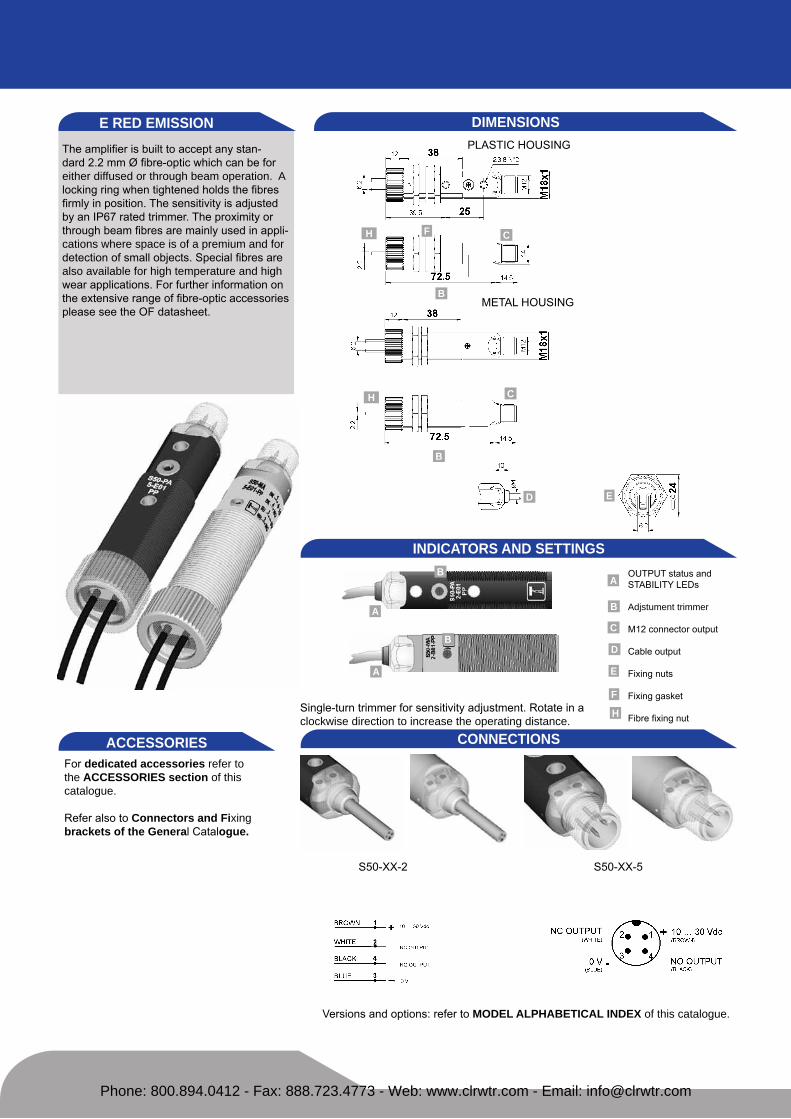
the amplifier is built to accept any stan-dard 2.2 mm Ø fibre-optic which can be for either diffused or through beam operation. A locking ring when tightened holds the fibres firmly in position. the sensitivity is adjusted by an IP67 rated trimmer. the proximity or through beam fibres are mainly used in appli-cations where space is of a premium and for detection of small objects. special fibres are also available for high temperature and high wear applications. for further information on the extensive range of fibre-optic accessories please see the of datasheet.
DIMeNSIONSPLastIc housIng
metaL housIng
INDICATORS AND SeTTINGS
s50-xx-2 s50-xx-5
CONNeCTIONSACCeSSORIeSfor dedicated accessories refer to the ACCeSSORIeS section of this catalogue.
refer also to Connectors and Fixing brackets of the General catalogue.
versions and options: refer to MODeL ALPHABeTICAL INDex of this catalogue.
e ReD eMISSION
outPut status andstabILIty Leds
Adjstument trimmer
m12 connector output
cable output
fixing nuts
fixing gasket
fibre fixing nut
A
C
D
e
H
H
H
Fsingle-turn trimmer for sensitivity adjustment. rotate in a clockwise direction to increase the operating distance.
B
B
B
B
A
A
F C
C
D e
B
Phone: 800.894.0412 - Fax: 888.723.4773 - Web: www.clrwtr.com - Email: [email protected]

TeCHNICAL DATATeCHNICAL NOTeS1Limit values2 average life of 100.000 h with tA = +25 °c3 270° single-turn trimmer4 Pvc, 4 x 0.14 mm2
5 compatible with quick connection systems 6 a - reverse polarity protection b - overload and short-circuit protection on receiver outputs
S50-
PA-2
-E01
-NN
S50-
PA-2
-E01
-PP
S50-
PA-5
-E01
-NN
S50-
PA-5
-E01
-PP
S50-
MA
-2-E
01-N
N
S50-
MA
-2-E
01-P
P
S50-
MA
-5-E
01-N
N
S50-
MA
-5-E
01-P
P
Operating distance:proximity 3 cm (of-42-st-20 standard fibres) ● ● ● ● ● ● ● ●
through beam 10 cm (of-43-st-20 standard fibres) ● ● ● ● ● ● ● ●Power supply: 10 ... 30 vdc 1 ● ● ● ● ● ● ● ●
Ripple: ≤ 2 vpp ● ● ● ● ● ● ● ●Consumption: ≤ 35 ma ● ● ● ● ● ● ● ●
Light emission: red Led 660 nm2 ● ● ● ● ● ● ● ●Setting: sensitivity trimmer 3 ● ● ● ● ● ● ● ●
Indicators: yellow outPut Led ● ● ● ● ● ● ● ●green stabILIty ● ● ● ● ● ● ● ●
Output type: PnP, no and nc ● ● ● ●nPn, no and nc ● ● ● ●
Output current: ≤ 100 ma ● ● ● ● ● ● ● ●Saturation voltage: ≤ 2 v ● ● ● ● ● ● ● ●
Response time: 0.5 ms ● ● ● ● ● ● ● ●Switching frequency: 1 khz ● ● ● ● ● ● ● ●
Operating mode: dark on no / light on nc ● ● ● ● ● ● ● ●Connection: 2 m Ø 4 mm cable4 ● ● ● ●
m12 4-pole connector5 ● ● ● ●electrical protection: class 2 ● ● ● ● ● ● ● ●
Mechanical protection: IP67 ● ● ● ● ● ● ● ●Protection devices: a, b6 ● ● ● ● ● ● ● ●Housing material: Pbt ● ● ● ●
nickel plated brass ● ● ● ●Fibre fixing nut material: abs ● ● ● ● ● ● ● ●
Weight: 75 g max. ● ●25 g max. ● ●110 g max. ● ●60 g max. ● ●
Operating temperature: -25 ... +55°c ● ● ● ● ● ● ● ●Storage temperature: -25 ... +70°c ● ● ● ● ● ● ● ●Reference standard: en 60947-5-2 ● ● ● ● ● ● ● ●
SeLeCTION TABLe plastic - axial optics - 2 m cable
s50-Pa-2-e01-nn 952001650 nPn
s50-Pa-2-e01-PP 952001130 PnP
metal - axial optics - 2 m cable
s50-ma-2-e01-nn 952021880 nPn
s50-ma-2-e01-PP 952021040 PnP
plastic - axial optics - m12 connector
s50-Pa-5-e01-nn 952001540 nPn
s50-Pa-5-e01-PP 952001140 PnP
metal - axial optics - m12 connector
s50-ma-5-e01-nn 952021890 nPn
s50-ma-5-e01-PP 952021240 PnP
DeTeCTION DIAGRAMS
All the ordering codes and information are summarised in the last pages of this catalogue.
operating distance with standard fibres
* standard fibre-optics
excess gain - proximity * detection area - proximity *
excess gain - through beam * detection area - through beam *
grey 18% grey 18%
white 90%
white 90%
Standard fibre-optics:OF-42-ST-20 proximityOF-43-ST-20 through beam
high efficiency fibre-optics or accessory lenses can be used to obtain larger opera-ting distances. refer to Fibre-optics of the General Catalogue
Phone: 800.894.0412 - Fax: 888.723.4773 - Web: www.clrwtr.com - Email: [email protected]

the white light Led emission is designed for the detection of a large number of coloured or grey-scale contrasts, in order to detect print registration marks or similar. The easytouchtm setting procedures automati-cally selects the best detection conditions, simply by pressing the teach-in push-button once, in the presence of a reference mark. by pressing the teach-in push-button and holding it down until the green light on the rear of the sensor flashes, in the presence of the reference mark and then pressing the button again in the presence of the contrast you wish to ignore, a higher level of accuracy is obtained.
DIMeNSIONSPLastIc housIng
metaL housIng
INDICATORS AND SeTTINGS
s50-xx-2 s50-xx-5
CONNeCTIONSACCeSSORIeSfor dedicated accessories refer to the ACCeSSORIeS section of this catalogue.
refer also to Connectors and Fixing brackets of the General catalogue.
versions and options: refer to MODeL ALPHABeTICAL INDex of this catalogue.
W WHITe eMISSION
outPut status andready/ error Leds
teach-in push-button
m12 connector output
cable output
fixing nuts
fixing gasket
A
C
D
e
Fteach-in button for setting.easytouch™ provides two setting modes: standard or fine,both obtained by pressing the push-button only once. Plea-se refer to instructions manual for operating details.
B
B
BA
A
Phone: 800.894.0412 - Fax: 888.723.4773 - Web: www.clrwtr.com - Email: [email protected]

TeCHNICAL DATATeCHNICAL NOTeS1Limit values2 average life of 100.000 h with ta = +25 °c3 Pvc, 4 x 0.14 mm2
4 compatible with quick connection systems 5 a - reverse polarity protection b - overload and short-circuit protection on receiver outputs
S50-
PA-2
-W03
-NN
S50-
PA-2
-W03
-PP
S50-
PA-5
-W03
-NN
S50-
PA-5
-W03
-PP
S50-
MA
-2-W
03-N
N
S50-
MA
-2-W
03-P
P
S50-
MA
-5-W
03-N
N
S50-
MA
-5-W
03-P
P
Operating distance: 10 mm ● ● ● ● ● ● ● ●Depth of field (max.): ± 2 mm ● ● ● ● ● ● ● ●
Power supply: 10 ... 30 vdc 1 ● ● ● ● ● ● ● ●Ripple: ≤ 2 vpp ● ● ● ● ● ● ● ●
Consumption: ≤ 25 ma ● ● ● ● ● ● ● ●Light emission: white Led 400 - 700 nm2 ● ● ● ● ● ● ● ●Spot dimension: approx. 4.5 mm at 10 mm ● ● ● ● ● ● ● ●
Minimum detectable object: 0.5 mm ● ● ● ● ● ● ● ●Setting: teach-in push-button ● ● ● ● ● ● ● ●
Setting procedure: teach-in easytouchtm ● ● ● ●Indicators: yellow outPut Led ● ● ● ●
green / red ready / error Led ● ● ● ● ● ● ● ●Output type: PnP, no and nc ● ● ● ● ● ● ● ●
nPn, no and nc ● ● ● ● ● ● ● ●Output current: ≤ 100 ma ● ● ● ● ● ● ● ●
Saturation voltage: ≤ 2 v ● ● ● ● ● ● ● ●Response time: 100 ms ● ● ● ● ● ● ● ●
Switching frequency: 5 khz ● ● ● ● ● ● ● ●Operating mode: dark with easytouchtm ● ● ● ● ● ● ● ●
automatic dark / light with fine acq. ● ● ● ● ● ● ● ●Connection: 2 m Ø 4 mm cable3 ● ● ● ●
m12 4-pole connector4 ● ● ● ●electrical protection: class 2 ● ● ● ● ● ● ● ●
Mechanical protection: IP67 ● ● ● ● ● ● ● ●Protection devices: a, b ● ● ● ● ● ● ● ●Housing material: Pbt ● ● ● ●
nickel plated brass ● ● ● ●Lens material: Pmma ● ● ● ● ● ● ● ●
Weight: 75 g max. ● ●25 g max. ● ●110 g max. ● ●60 g max. ● ●
Operating temperature: -25 ... +55°c ● ● ● ● ● ● ● ●Storage temperature: -25 ... +70°c ● ● ● ● ● ● ● ●Reference standard: en 60947-5-2 ● ● ● ● ● ● ● ●
SeLeCTION TABLe plastic - axial optics - 2 m cable
s50-Pa-2-w03-nn 952001710 nPn
s50-Pa-2-w03-PP 952001320 PnP
metal - axial optics - 2 m cable
s50-ma-2-w03-nn 952021590 nPn
s50-ma-2-w03-PP 952021110 PnP
plastic - axial optics - m12 connector
s50-Pa-5-w03-nn 952001600 nPn
s50-Pa-5-w03-PP 952001330 PnP
metal - axial optics - m12 connector
s50-ma-5-w03-nn 952021750 nPn
s50-ma-5-w03-PP 952021310 PnP
DeTeCTION DIAGRAMS
All the ordering codes and information are summarised in the last pages of this catalogue.
operating distance
II3dg
operating distance
rel
ativ
e se
nsiti
vity
Phone: 800.894.0412 - Fax: 888.723.4773 - Web: www.clrwtr.com - Email: [email protected]

the uv light Led emission detects any luminescent reference, even on very reflec-tive surfaces, such as ceramics, metal or mirrored glass. the easytouchtm setting procedures fixes automatically the best detection conditions, simply by pressing the teach-in push-button once, with the lumine-scent object present. by pressing the teach-in push-button and holding it down until the green light on the rear of the sensor flashes, with the luminescent object present and then pressing the button again in the presence of a luminescent reference you wish to ignore, a higher level of accuracy is obtained.
DIMeNSIONS
PLastIc housIng
metaL housIng
INDICATORS AND SeTTINGS
s50-xx-2 s50-xx-5
CONNeCTIONSACCeSSORIeSfor dedicated accessories refer to the ACCeSSORIeS section of this catalogue.
refer also to Connectors and Fixing brackets of the General catalogue.
versions and options: refer to MODeL ALPHABeTICAL INDex of this catalogue.
U UV eMISSION
outPut status andready/ error Leds
teach-in push-button
m12 connector output
cable output
fixing nuts
fixing gasket
A
C
D
e
Fteach-in button for setting.easytouch™ provides two setting modes: standard or fine,both obtained by pressing the push-button only once. Plea-se refer to instructions manual for operating details.
B
B
BA
A
Phone: 800.894.0412 - Fax: 888.723.4773 - Web: www.clrwtr.com - Email: [email protected]

TeCHNICAL DATATeCHNICAL NOTeS1Limit values2 average life of 100.000 h with ta = +25 °c3 Pvc, 4 x 0.14 mm2
4 compatible with quick connection systems 5 a - reverse polarity protection b - overload and short-circuit protection on receiver outputs
S50-
PA-2
-U03
-NN
S50-
PA-2
-U03
-PP
S50-
PA-5
-U03
-NN
S50-
PA-5
-U03
-PP
S50-
MA
-2-U
03-N
N
S50-
MA
-2-U
03-P
P
S50-
MA
-5-U
03-N
N
S50-
MA
-5-U
03-P
P
Operating distance: 8 ... 20 mm ● ● ● ● ● ● ● ●Power supply: 10 ... 30 vdc 1 ● ● ● ● ● ● ● ●
Ripple: ≤ 2 vpp ● ● ● ● ● ● ● ●Consumption: ≤ 25 ma ● ● ● ● ● ● ● ●
Light emission: uv Led 370 nm2 ● ● ● ● ● ● ● ●Spot dimension: approx. 3 mm at 20 mm ● ● ● ● ● ● ● ●
Minimum detectable object: 0.5 mm ● ● ● ● ● ● ● ●Setting: teach-in push-button ● ● ● ● ● ● ● ●
Setting procedure: teach-in easytouchtm ● ● ● ● ● ● ● ●Indicators: yellow outPut Led ● ● ● ● ● ● ● ●
green / red ready / error Led ● ● ● ● ● ● ● ●Output type: PnP, no and nc ● ● ● ●
nPn, no and nc ● ● ● ●Output current: ≤ 100 ma ● ● ● ● ● ● ● ●
Saturation voltage: ≤ 2 v ● ● ● ● ● ● ● ●Response time: 500 ms ● ● ● ● ● ● ● ●
Switching frequency: 1 khz ● ● ● ● ● ● ● ●Operating mode: dark with easytouchtm ● ● ● ● ● ● ● ●
automatic dark / light with fine acq. ● ● ● ● ● ● ● ●Connection: 2 m Ø 4 mm cable3 ● ● ● ●
m12 4-pole connector4 ● ● ● ●electrical protection: class 2 ● ● ● ● ● ● ● ●
Mechanical protection: IP67 ● ● ● ● ● ● ● ●Protection devices: a, b5 ● ● ● ● ● ● ● ●Housing material: Pbt ● ● ● ●
nickel plated brass ● ● ● ●Lens material: Pmma ● ● ● ● ● ● ● ●
Weight: 75 g max. ● ●25 g max. ● ●110 g max. ● ●60 g max. ● ●
Operating temperature: -25 ... +55°c ● ● ● ● ● ● ● ●Storage temperature: -25 ... +70°c ● ● ● ● ● ● ● ●Reference standard: en 60947-5-2 ● ● ● ● ● ● ● ●
SeLeCTION TABLe plastic - axial optics - 2 m cable
s50-Pa-2-u03-nn 952001700 nPn
s50-Pa-2-u03-PP 952001300 PnP
metal - axial optics - 2 m cable
s50-ma-2-u03-nn 952021580 nPn
s50-ma-2-u03-PP 952021100 PnP
plastic - axial optics - m12 connector
s50-Pa-5-u03-nn 952001590 nPn
s50-Pa-5-u03-PP 952001310 PnP
metal - axial optics - m12 connector
s50-ma-5-u03-nn 952021740 nPn
s50-ma-5-u03-PP 952021300 PnP
DeTeCTION DIAGRAMS
All the ordering codes and information are summarised in the last pages of this catalogue.
operating distance
II3dg
operating distance
rel
ativ
e se
nsiti
vity
Phone: 800.894.0412 - Fax: 888.723.4773 - Web: www.clrwtr.com - Email: [email protected]

TeCHNOLOGY
ACCeSSORIeS
ACCeSSORY SeLeCTION AND ORDeR INFORMATION
multi-layer fine-line Pcb
chip-size components, integrated circuits in 8 bumps flip-chip
analogue digital asIc
Power asIc for antivalent outputs
m12 custom connector compatible with quick connection systems. the four terminals are cone-shaped to facilitate the direct insertion in the cable conductors (4 x 0,5 mm2)
housing and fixing nuts in indeformable plastic providing excellent resistance against hostile environ-ments. Indelible laser marking
A modular product developed for the automation of the assembling and testing process necessary to guarantee intrinsic quality, repeatability and reliability. one-piece-flow management for improved service
1 6
2
3
4
7
5
easytouch™ is a datasensor patent-covered technology that allows a rapid and safe setting of micro-controlled sensors equipped with a teach-in push-button. a pressure longer than two seconds of the push-button allows a good adjustment of the sensitivity th-reshold. easytouch™ is the easiest and fastest calibration procedure available on the market. the instructions on how to best use easytouch™ are given in the product’s instruction manual.
The series is compatible with all the Datalogic Automation accessories already developed for tubular sensors.In the General Catalogue refer to:- CS connectors - R reflectors- OF fibre-optics - ST fixing brackets new accessories dedicated to the S50 series have been developed to cover all the fixing requirements and to improve the functioning. In particular eASYin™ is an innovative fixing system that can be used only for the plastic flat version, that allows a fast and safe positioning of the sensor, facilitating the adjustment as well as the locking and unlocking.
modeL descrIPtIon order n°
st-5010 m18/14 fixing bracket 95acc5230
st-5011 m18 fixing bracket 95acc5240
st-5012 m18 fixing bracket 95acc5250
st-5017 m18 fixing bracket 95acc5270
s50 easy-In m18/14 easyin™ adjustable fixing support 95acc5300
JoInt-18 m18 jointed support 95acc5220
swIng-18 adjustable support for plastic tubular m18 sensors 895000006
mIcro-18 support with micrometric regulation for tubular m18 sensors 95acc1380
sP-40 fixed support for tubular m18 sensors 95acc1370
mek-Proof front protection g5000001
refer also to Accessories for sensors of the General Catalogue
Phone: 800.894.0412 - Fax: 888.723.4773 - Web: www.clrwtr.com - Email: [email protected]

DIMeNSION ACCeSSORIeSs50 easyin™
JoInt-18
Phone: 800.894.0412 - Fax: 888.723.4773 - Web: www.clrwtr.com - Email: [email protected]

ST-5010
ST-5012
ST-5011
ST-5017
Phone: 800.894.0412 - Fax: 888.723.4773 - Web: www.clrwtr.com - Email: [email protected]

MICRO-18
SP-40
SWING-18
MeK PROOF
Phone: 800.894.0412 - Fax: 888.723.4773 - Web: www.clrwtr.com - Email: [email protected]

MODeL SeLeCTION AND ORDeR INFORMATIONPLASTIC FLAT HOUSING WITH AxIAL OPTICS
modeL code n° oPtIc functIon Page
s50-Pa-2-a00-nn 952002090 retroreflex 10
s50-Pa-2-a00-PP 952002080 retroreflex 10
s50-Pa-2-b01-nn 952001610 polarised retroreflex 12
s50-Pa-2-b01-PP 952001010 polarised retroreflex 12
s50-Pa-2-c01-nn 952001620 long diffuse proximity 22
s50-Pa-2-c01-PP 952001050 long diffuse proximity 22
s50-Pa-2-c10-nn 952001630 short diffuse proximity 18
s50-Pa-2-c10-PP 952001240 short diffuse proximity 18
s50-Pa-2-c21-nn 952002170 midi diffuse proximity 20
s50-Pa-2-c21-PP 952002160 midi diffuse proximity 20
s50-Pa-2-d00-nn 952001640 fixed focus proximity 24
s50-Pa-2-d00-PP 952001090 fixed focus proximity 24
s50-Pa-2-e01-nn 952001650 fibre-optic amplifier 34
s50-Pa-2-e01-PP 952001130 fibre-optic amplifier 34
s50-Pa-2-f01-nn 952001660 receiver 2
s50-Pa-2-f01-PP 952001150 receiver 2
s50-Pa-2-g00-xg 952001190 emitter 2
s50-Pa-2-m03-nn 952001670 background suppression 28
s50-Pa-2-m03-PP 952001230 background suppression 28
s50-Pa-2-t01-nn 952001690 retroreflex for transparents 16
s50-Pa-2-t01-PP 952001260 retroreflex for transparents 16
s50-Pa-2-u03-nn 952001700 luminescence sensor 38
s50-Pa-2-u03-PP 952001300 luminescence sensor 38
s50-Pa-2-w03-nn 952001710 contrast sensor 36
s50-Pa-2-w03-PP 952001320 contrast sensor 36
s50-Pa-5-a00-nn 952002110 retroreflex 10
s50-Pa-5-a00-PP 952002100 retroreflex 10
s50-Pa-5-b01-nn 952001500 polarised retroreflex 12
s50-Pa-5-b01-PP 952001020 polarised retroreflex 12
s50-Pa-5-c01-nn 952001510 long diffuse proximity 22
s50-Pa-5-c01-PP 952001060 long diffuse proximity 22
s50-Pa-5-c10-nn 952001520 short diffuse proximity 18
s50-Pa-5-c10-PP 952001250 short diffuse proximity 18
s50-Pa-5-c21-nn 952002190 midi diffuse proximity 20
s50-Pa-5-c21-PP 952002180 midi diffuse proximity 20
s50-Pa-5-d00-nn 952001530 fixed focus proximity 24
s50-Pa-5-d00-PP 952001100 fixed focus proximity 24
s50-Pa-5-e01-nn 952001540 fibre-optic amplifier 34
s50-Pa-5-e01-PP 952001140 fibre-optic amplifier 34
s50-Pa-5-f01-nn 952001550 receiver 2
s50-Pa-5-f01-PP 952001160 receiver 2
s50-Pa-5-g00-xg 952001200 emitter 2
s50-Pa-5-m03-nn 952001560 background suppression 28
s50-Pa-5-m03-PP 952001000 background suppression 28
s50-Pa-5-t01-nn 952001580 retroreflex for transparents 16
s50-Pa-5-t01-PP 952001270 retroreflex for transparents 16
s50-Pa-5-u03-nn 952001590 luminescence sensor 38
PLASTIC FLAT HOUSING WITH AxIAL OPTICS
modeL code n° oPtIc functIon Page
s50-Pa-5-u03-PP 952001310 luminescence sensor 38
s50-Pa-5-w03-nn 952001600 contrast sensor 36
s50-Pa-5-w03-PP 952001330 contrast sensor 36
PLASTIC FLAT HOUSING WITH RADIAL OPTICS
s50-Pr-2-b01-nn 952001780 polarised retroreflex 12
s50-Pr-2-b01-PP 952001030 polarised retroreflex 12
s50-Pr-2-c01-nn 952001790 long diffuse proximity 22
s50-Pr-2-c01-PP 952001070 long diffuse proximity 22
s50-Pr-2-c10-nn 952001800 short diffuse proximity 18
s50-Pr-2-c10-PP 952001490 short diffuse proximity 18
s50-Pr-2-d00-nn 952001810 fixed focus proximity 24
s50-Pr-2-d00-PP 952001110 fixed focus proximity 24
s50-Pr-2-f01-nn 952001820 receiver 2
s50-Pr-2-f01-PP 952001170 receiver 2
s50-Pr-2-g00-xg 952001210 emitter 2
s50-Pr-2-t01-nn 952001830 retroreflex for transparents 16
s50-Pr-2-t01-PP 952001280 retroreflex for transparents 16
s50-Pr-5-b01-nn 952001720 polarised retroreflex 12
s50-Pr-5-b01-PP 952001040 polarised retroreflex 12
s50-Pr-5-c01-nn 952001730 long diffuse proximity 22
s50-Pr-5-c01-PP 952001080 long diffuse proximity 22
s50-Pr-5-c10-nn 952001740 short diffuse proximity 18
s50-Pr-5-c10-PP 952001480 short diffuse proximity 18
s50-Pr-5-d00-nn 952001750 fixed focus proximity 24
s50-Pr-5-d00-PP 952001120 fixed focus proximity 24
s50-Pr-5-f01-nn 952001760 receiver 2
s50-Pr-5-f01-PP 952001180 receiver 2
s50-Pr-5-g00-xg 952001220 emitter 2
s50-Pr-5-t01-nn 952001770 retroreflex for transparents 16
s50-Pr-5-t01-PP 952001290 retroreflex for transparents 16
PLASTIC FLAT HOUSING WITH LATeRAL OPTICS
s50-Ps-2-m03-nn 952001900 background suppression 30
s50-Ps-2-m03-PP 952001910 background suppression 30
s50-Ps-5-m03-nn 952001920 background suppression 30
s50-Ps-5-m03-PP 952001930 background suppression 30
PLASTIC FLAT HOUSING WITH LASeR AxIAL OPTICS
s50-PL-2-b01-nn 952001870 laser retroreflex 14
s50-PL-2-b01-PP 952001360 laser retroreflex 14
s50-PL-2-c01-nn 952001880 laser proximity 26
s50-PL-2-c01-PP 952001380 laser proximity 26
s50-PL-2-f01-nn 952001890 laser receiver 6
s50-PL-2-f01-PP 952001400 laser receiver 6
s50-PL-2 g00-xg 952001420 laser emitter 6
s50-PL-5-b01-nn 952001840 laser retroreflex 14
s50-PL-5-b01-PP 952001370 laser retroreflex 14
s50-PL-5-c01-nn 952001850 laser proximity 26
s50-PL-5-c01-PP 952001390 laser proximity 26
s50-PL-5-f01-nn 952001860 laser receiver 6
s50-PL-5-f01-PP 952001410 laser receiver 6
s50-PL-5-g00-xg 952001430 laser emitter 6
Phone: 800.894.0412 - Fax: 888.723.4773 - Web: www.clrwtr.com - Email: [email protected]

MODeL SeLeCTION AND ORDeR INFORMATIONPLASTIC FLAT HOUSING WITH LASeR RADIAL OPTICS
modeL code n° oPtIc functIon Page
s50-Ph-2-b01-nn 952001950 laser retroreflex 14
s50-Ph-2-b01-PP 952001940 laser retroreflex 14
s50-Ph-2-c01-nn 952001990 laser proximity 26
s50-Ph-2-c01-PP 952001980 laser proximity 26
s50-Ph-2-f01-nn 952002030 laser receiver 6
s50-Ph-2-f01-PP 952002020 laser receiver 6
s50-Ph-2 g00-xg 952002060 laser emitter 6
s50-Ph-5-b01-nn 952001970 laser retroreflex 14
s50-Ph-5-b01-PP 952001960 laser retroreflex 14
s50-Ph-5-c01-nn 952002010 laser proximity 26
s50-Ph-5-c01-PP 952002000 laser proximity 26
s50-Ph-5-f01-nn 952002050 laser receiver 6
s50-Ph-5-f01-PP 952002040 laser receiver 6
s50-Ph-5-g00-xg 952002070 laser emitter 6
MeTAL CYLINDRICAL HOUSING WITH AxIAL OPTICS
s50-ma-2-a00-nn 952022090 retroreflex 10
s50-ma-2-a00-PP 952022080 retroreflex 10
s50-ma-2-b01-nn 952021500 polarised retroreflex 12
s50-ma-2-b01-PP 952021000 polarised retroreflex 12
s50-ma-2-c01-nn 952021510 long diffuse proximity 22
s50-ma-2-c01-PP 952021010 long diffuse proximity 22
s50-ma-2-c10-nn 952021520 short diffuse proximity 18
s50-ma-2-c10-PP 952021020 short diffuse proximity 18
s50-ma-2-c21-nn 952022130 midi diffuse proximity 20
s50-ma-2-c21-PP 952022120 midi diffuse proximity 20
s50-ma-2-d00-nn 952021530 fixed focus proximity 24
s50-ma-2-d00-PP 952021030 fixed focus proximity 24
s50-ma-2-e01-nn 952021880 fibre-optic amplifier 34
s50-ma-2-e01-PP 952021040 fibre-optic amplifier 34
s50-ma-2-f01-nn 952021540 receiver 4
s50-ma-2-f01-PP 952021050 receiver 4
s50-ma-2-g00-xg 952021060 emitter 4
s50-ma-2-m03-nn 952021550 background suppression 28
s50-ma-2-m03-PP 952021070 background suppression 28
s50-ma-2-t01-nn 952021570 retroreflex for transparents 16
s50-ma-2-t01-PP 952021090 retroreflex for transparents 16
s50-ma-2-u03-nn 952021580 luminescence sensor 38
s50-ma-2-u03-PP 952021100 luminescence sensor 38
s50-ma-2-w03-nn 952021590 contrast sensor 36
s50-ma-2-w03-PP 952021110 contrast sensor 36
s50-ma-5-a00-nn 952022110 retroreflex 10
s50-ma-5-a00-PP 952022100 retroreflex 10
s50-ma-5-b01-nn 952021660 polarised retroreflex 12
s50-ma-5-b01-PP 952021200 polarised retroreflex 12
s50-ma-5-c01-nn 952021670 long diffuse proximity 22
s50-ma-5-c01-PP 952021210 long diffuse proximity 22
s50-ma-5-c10-nn 952021680 short diffuse proximity 18
s50-ma-5-c10-PP 952021220 short diffuse proximity 18
MeTAL CYLINDRICAL HOUSING WITH AxIAL OPTICS
modeL code n° oPtIc functIon Page
s50-ma-5-c21-nn 952022150 midi diffuse proximity 20
s50-ma-5-c21-PP 952022140 midi diffuse proximity 20
s50-ma-5-d00-nn 952021690 fixed focus proximity 24
s50-ma-5-d00-PP 952021230 fixed focus proximity 24
s50-ma-5-e01-nn 952021890 fibre-optic amplifier 34
s50-ma-5-e01-PP 952021240 fibre-optic amplifier 34
s50-ma-5-f01-nn 952021700 receiver 4
s50-ma-5-f01-PP 952021250 receiver 4
s50-ma-5-g00-xg 952021260 emitter 4
s50-ma-5-m03-nn 952021710 background suppression 28
s50-ma-5-m03-PP 952021270 background suppression 28
s50-ma-5-t01-nn 952021730 retroreflex for transparents 16
s50-ma-5-t01-PP 952021290 retroreflex for transparents 16
s50-ma-5-u03-nn 952021740 luminescence sensor 38
s50-ma-5-u03-PP 952021300 luminescence sensor 38
s50-ma-5-w03-nn 952021750 contrast sensor 36
s50-ma-5-w03-PP 952021310 contrast sensor 36
MeTAL CYLINDRICAL HOUSING WITH RADIAL OPTICS
s50-mr-2-b01-nn 952021600 polarised retroreflex 12
s50-mr-2-b01-PP 952021140 polarised retroreflex 12
s50-mr-2-c01-nn 952021610 long diffuse proximity 22
s50-mr-2-c01-PP 952021150 long diffuse proximity 22
s50-mr-2-c10-nn 952021620 short diffuse proximity 18
s50-mr-2-c10-PP 952021490 short diffuse proximity 18
s50-mr-2-d00-nn 952021630 fixed focus proximity 24
s50-mr-2-d00-PP 952021160 fixed focus proximity 24
s50-mr-2-f01-nn 952021640 receiver 4
s50-mr-2-f01-PP 952021170 receiver 4
s50-mr-2-g00-xg 952021180 emitter 4
s50-mr-2-t01-nn 952021650 retroreflex for transparents 16
s50-mr-2-t01-PP 952021190 retroreflex for transparents 16
s50-mr-5-b01-nn 952021760 polarised retroreflex 12
s50-mr-5-b01-PP 952021340 polarised retroreflex 12
s50-mr-5-c01-nn 952021770 long diffuse proximity 22
s50-mr-5-c01-PP 952021350 long diffuse proximity 22
s50-mr-5-c10-nn 952021780 short diffuse proximity 18
s50-mr-5-c10-PP 952021480 short diffuse proximity 18
s50-mr-5-d00-nn 952021790 fixed focus proximity 24
s50-mr-5-d00-PP 952021360 fixed focus proximity 24
s50-mr-5-f01-nn 952021800 receiver 4
s50-mr-5-f01-PP 952021370 receiver 4
s50-mr-5-g00-xg 952021380 emitter 4
s50-mr-5-t01-nn 952021810 retroreflex for transparents 16
s50-mr-5-t01-PP 952021390 retroreflex for transparents 16
Phone: 800.894.0412 - Fax: 888.723.4773 - Web: www.clrwtr.com - Email: [email protected]

MODeL SeLeCTION AND ORDeR INFORMATION
MODeL CODING TABLe
MeTAL CYLINDRICAL HOUSING WITH LATeRAL OPTICS
modeL code n° oPtIc functIon Page
s50-ms-2-m03-nn 952021900 background suppression 30
s50-ms-2-m03-PP 952021910 background suppression 30
s50-ms-5-m03-nn 952021920 background suppression 30
s50-ms-5-m03-PP 952021930 background suppression 30
MeTAL CYLINDRICAL HOUSING WITH LASeR AxIAL OPTICS
s50-mL-2-b01-nn 952021820 laser retroreflex 14
s50-mL-2-b01-PP 952021400 laser retroreflex 14
s50-mL-2-c01-nn 952021830 laser proximity 26
s50-mL-2-c01-PP 952021410 laser proximity 26
s50-mL-2-f01-nn 952021840 laser receiver 8
s50-mL-2-f01-PP 952021420 laser receiver 8
s50-mL-2-g00-xg 952021430 laser emitter 8
s50-mL-5-b01-nn 952021850 laser retroreflex 14
s50-mL-5-b01-PP 952021440 laser retroreflex 14
s50-mL-5-c01-nn 952021860 laser proximity 26
s50-mL-5-c01-PP 952021450 laser proximity 26
s50-mL-5-f01-nn 952021870 laser receiver 8
s50-mL-5-f01-PP 952021460 laser receiver 8
s50-mL-5-g00-xg 952021470 laser emitter 8
MeTAL CYLINDRICAL HOUSING WITH LASeR RADIAL OPTICS
modeL code n° oPtIc functIon Page
s50-mh-2-b01-nn 952021940 laser retroreflex 14
s50-mh-2-b01-PP 952021950 laser retroreflex 14
s50-mh-2-c01-nn 952021990 laser proximity 26
s50-mh-2-c01-PP 952021980 laser proximity 26
s50-mh-2-f01-nn 952022030 laser receiver 8
s50-mh-2-f01-PP 952022020 laser receiver 8
s50-mh-2-g00-xg 952022060 laser emitter 8
s50-mh-5-b01-nn 952021970 laser retroreflex 14
s50-mh-5-b01-PP 952021960 laser retroreflex 14
s50-mh-5-c01-nn 952022010 laser proximity 26
s50-mh-5-c01-PP 952022000 laser proximity 26
s50-mh-5-f01-nn 952022050 laser receiver 8
s50-mh-5-f01-PP 952022040 laser receiver 8
s50-mh-5-g00-xg 952022070 laser emitter 8
Note: Not all code combinations are available. Please refer to alphabetical model index for the list of available models.
the company endeavours to continuously improve and renew its products; for this reason the technical data and contents of this catalogue may undergo variations without prior notice. for correct installation and use, the company can guarantee only the data indicated in the instruction manual supplied with the products.
UNI EN ISO9001
Phone: 800.894.0412 - Fax: 888.723.4773 - Web: www.clrwtr.com - Email: [email protected]


![Lenovo S50 Series - CNET Contentcdn.cnetcontent.com › a1 › cb › a1cbe111-977a-4bab-87d7-64a8d78a674c.pdfVersion 2.0 Machine type: F0BA [S50-30] 2015.02 Lenovo S50 Series User](https://img.pdfslide.net/doc/110x75/60bc5e9cced4c810a35b3bc3/lenovo-s50-series-cnet-a-a1-a-cb-a-a1cbe111-977a-4bab-87d7-64a8d78a674cpdf.jpg)