Embed Size (px)
Citation preview
1
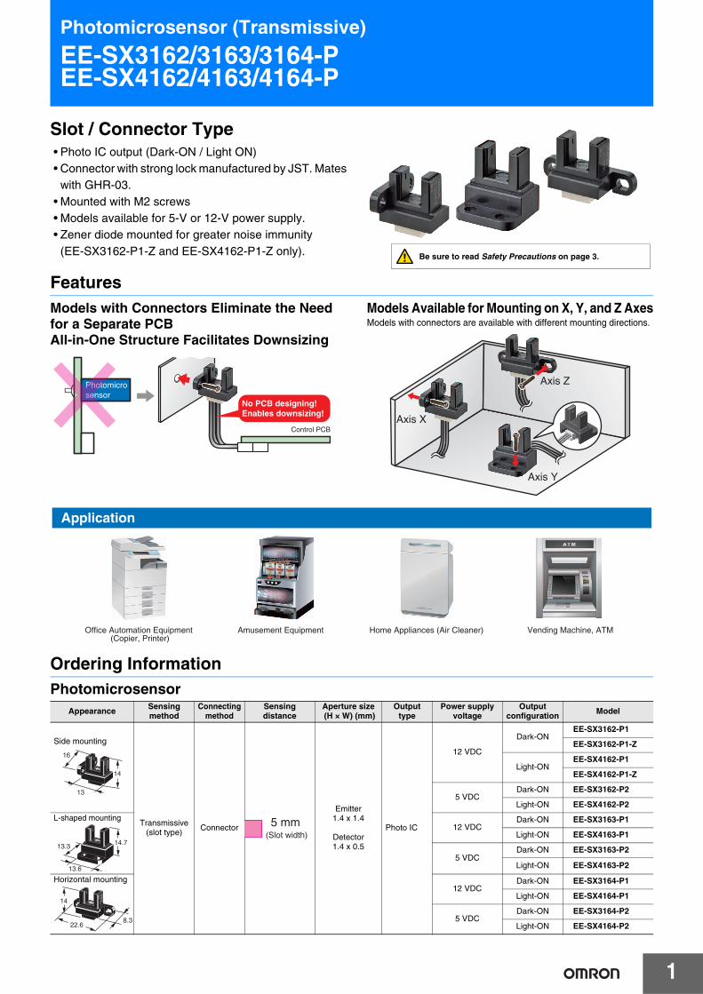
Photomicrosensor (Transmissive)
EE-SX3162/3163/3164-PEE-SX4162/4163/4164-P
Slot / Connector Type• Photo IC output (Dark-ON / Light ON)• Connector with strong lock manufactured by JST. Mates
with GHR-03.• Mounted with M2 screws• Models available for 5-V or 12-V power supply.• Zener diode mounted for greater noise immunity
(EE-SX3162-P1-Z and EE-SX4162-P1-Z only).
FeaturesModels with Connectors Eliminate the Need for a Separate PCBAll-in-One Structure Facilitates Downsizing
Models Available for Mounting on X, Y, and Z AxesModels with connectors are available with different mounting directions.
Ordering InformationPhotomicrosensor
Photomicrosensor
Control PCB
No PCB designing!Enables downsizing!
Axis X
Axis Z
Axis Y
Appearance Sensing method
Connecting method
Sensing distance
Aperture size (H × W) (mm)
Output type
Power supply voltage
Output configuration Model
Side mounting
Transmissive(slot type) Connector
Emitter1.4 x 1.4
Detector1.4 x 0.5
Photo IC
12 VDC
Dark-ONEE-SX3162-P1
EE-SX3162-P1-Z
Light-ONEE-SX4162-P1
EE-SX4162-P1-Z
5 VDCDark-ON EE-SX3162-P2
Light-ON EE-SX4162-P2
L-shaped mounting12 VDC
Dark-ON EE-SX3163-P1
Light-ON EE-SX4163-P1
5 VDCDark-ON EE-SX3163-P2
Light-ON EE-SX4163-P2
Horizontal mounting12 VDC
Dark-ON EE-SX3164-P1
Light-ON EE-SX4164-P1
5 VDCDark-ON EE-SX3164-P2
Light-ON EE-SX4164-P2
Application
Office Automation Equipment (Copier, Printer)
Amusement Equipment Home Appliances (Air Cleaner) Vending Machine, ATM
14
16
13
5 mm (Slot width)
14.713.3
13.6
14
8.322.6
Be sure to read Safety Precautions on page 3.

EE-SX3162/3163/3164-P EE-SX4162/4163/4164-P
2
Ratings, Characteristics and Exterior SpecificationsAbsolute Maximum Ratings (Ta = 25°C)
* Even if the specified conditions are met, perform derating of the voltage and current as required by the temperature rating diagram. Also, do not expose the product to freezing or condensation.
Exterior Specifications
Electrical and Optical Characteristics
(Ta = 25°C)
*1. The value of the response frequency is measured by rotating the disk as shown below.
*2. Only with models ending in -Z.
Engineering Data (Reference value)
Item Symbol
Rated value
Unit Remarks
EE-SX3162-P1EE-SX3162-P1-ZEE-SX3163-P1EE-SX3164-P1EE-SX4162-P1
EE-SX4162-P1-ZEE-SX4163-P1EE-SX4164-P1
EE-SX3162-P2EE-SX3163-P2EE-SX3164-P2EE-SX4162-P2EE-SX4163-P2EE-SX4164-P2
Power supply voltage VCC 13.2 DC 5.5 DC V —
Output voltage VOUT 13.2 V —
Output current IOUT 16 mA —
Permissible output dissipation
POUT 80 mW —*
Operating temperature Topr -20 to +85 °C —*
Storage temperature Tstg -30 to +85 °C —*
Appearance Side mounting L-shaped mounting
Horizontal mounting
Item
EE-SX3162-P1EE-SX3162-P1-ZEE-SX4162-P1
EE-SX4162-P1-ZEE-SX3162-P2EE-SX4162-P2
EE-SX3163-P1EE-SX4163-P1EE-SX3163-P2EE-SX4163-P2
EE-SX3164-P1EE-SX4164-P1EE-SX3164-P2EE-SX4164-P2
Connecting method Connector
Weight Approx. 1.2 g Approx.1.4 g Approx. 1.1 g
Material
Case Polybutylene terephthalate (PBT)
Emitter and receiver sections
Polyphenylene sulfide (PPS)
Item
SymbolRated value
12 VDC model 5 VDC model
Dark-ON
EE-SX3162-P1EE-SX3162-P1-ZEE-SX3163-P1EE-SX3164-P1
EE-SX3162-P2EE-SX3163-P2EE-SX3164-P2
Light-ON
EE-SX4162-P1EE-SX4162-P1-ZEE-SX4163-P1EE-SX4164-P1
EE-SX4162-P2EE-SX4163-P2EE-SX4164-P2
Power supply voltage Vcc 10.8 to 13.2VDC 4.5 to 5.5 VDC
Current consumption Icc 25 mA max.
(With and without incident)
Low-level output voltage VOL
0.3 V max. (IOUT=16 mA)(Dark-ON: without incident, Light-ON: with incident)
High-level output voltage VOH
(VCC×0.9 V max. (VOUT=VCC, RL=47 k))(Dark-ON: with incident, Light-ON: without incident)
Response frequency f
3 kHz min.(VOUT=VCC, IOUT=16 mA *1)
1 kHz min.(VOUT=VCC, IOUT=16 mA *1,*2)
0.5 mm0.5 mm
2.1 mm
Disk
Fig 1. Output Allowable Dissipation vs.Ambient Temperature Characteristics
Fig 2. Sensing Position Characteristics(Typical)
Fig 3. Sensing Position Characteristics(Typical)
Ambient temperature Ta (°C)
0
20
40
60
80
100
-40 -30 -20 -10 0 10 20 30 40 50 60 70 80 90 100
Out
put a
llow
able
dis
sipa
tion
Pou
t (m
W)
Distance d (mm)-3
d1 = 0±0.3 mm VCC = 12 V Ta = 25°CRL = 47 kΩ
d1
-2 -1 0 1 2 3
d
(Center of axis)
OFF(ON)
Out
put t
rans
isto
r
Light interrupting plate
ON
OFF( )
Output OFF(High)
Output ON (Low)
-3
d2 = 0±0.7 mm
-2 -1 0 1 2 3
d
d2
Distance d (mm)
VCC = 12 V Ta = 25°CRL = 47 kΩ
(Center of axis)
Out
put t
rans
isto
r

EE-SX3162/3163/3164-P EE-SX4162/4163/4164-P
3
Safety PrecautionsTo ensure safe operation, be sure to read and follow the Instruction Manual provided with the Sensor.
This product is not designed or rated for ensuring safety of persons either directly or indirectly. Do not use it for such purposes.
Do not use the product with a voltage or current that exceeds the rated range.Applying a voltage or current that is higher than the rated range may result in explosion or fire.
Do not miswire such as the polarity of the power supply voltage.Otherwise the product may be damaged or it may burn.
Do not short-circuit the load.Otherwise explosion or burning may occur.
This product does not resist water. Do not use the product in places where water or oil may be sprayed onto the product.
Do not use the product in atmospheres or environments that exceed product ratings.Dispose of this product as industrial waste.
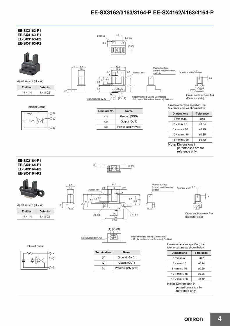
Dimensions and Internal Circuit (Unit: mm)
Photomicrosensor
CAUTION
Precautions for Safe Use
Precautions for Correct Use
6 (4.5)
Optical axis
2.7 13
11.6 7.5
8.3
4.5 5
(7)
6.4
(14)
A
A
Aperture width
(3) (1)(2)
Manufactured by JST
Recommended Mating Connectors:JST (Japan Solderless Terminal) GHR-03
2
16 11 8.3 5.6
2.5 5
Cross section view A-A(Detector side)
1.4
0.5
2.5 dia. 2-R1.55
Marked surface (brand, model number, and lot)
V
O
G
V
O
G
EE-SX3162-P1EE-SX3162-P1-ZEE-SX4162-P1EE-SX4162-P1-ZEE-SX3162-P2EE-SX4162-P2
Internal Circuit
Unless otherwise specified, the tolerances are as shown below.
Note: Dimensions in parentheses are for reference only.
Dimensions Tolerance
3 mm max. ±0.2
3 < mm 6 ±0.24
6 < mm 10 ±0.29
10 < mm 18 ±0.35
18 < mm 30 ±0.42
Terminal No. Name
(1) Ground (GND)
(2) Output (OUT)
(3) Power supply (VCC)
Aperture size (H × W)
Emitter Detector
1.4 × 1.4 1.4 × 0.5
Note: Only with models ending in -Z.
EE-SX3162/3163/3164-P EE-SX4162/4163/4164-P
4
Manufactured by JST (3) (1)(2) Recommended Mating Connectors:JST (Japan Solderless Terminal) GHR-03
(6.65)
(13.2)
1.4
0.5 5.6
5 8.3
2.4
2.5
7.5
8.4
5
13.6 12.4
2.7
6.4 7.5
2.7
6.3
A
A
2-R1.552.5 dia.
Optical axis Aperture width
Cross section view A-A(Detector side)
Marked surface (brand, model number, and lot)
V
O
G
EE-SX3163-P1EE-SX4163-P1EE-SX3163-P2EE-SX4163-P2
Internal Circuit
Aperture size (H × W)
Emitter Detector
1.4 × 1.4 1.4 × 0.5
Terminal No. Name
(1) Ground (GND)
(2) Output (OUT)
(3) Power supply (VCC)
Unless otherwise specified, the tolerances are as shown below.
Note: Dimensions in parentheses are for reference only.
Dimensions Tolerance
3 mm max. ±0.2
3 < mm 6 ±0.24
6 < mm 10 ±0.29
10 < mm 18 ±0.35
18 < mm 30 ±0.42
Optical axis
(8.5)
(4.15)
1.4
0.5 8.3 5.6
5
12.6
5
2.5
22.6
2.7
10 11.6
(7)
6.4
17.6
7.5
2.7
8.4
(14)
A
A
2
2.5 dia. 2-R1.55 Cross section view A-A(Detector side)
Aperture width
Recommended Mating Connectors:JST (Japan Solderless Terminal) GHR-03
Manufactured by JST
(3)(1) (2)
Marked surface (brand, model number, and lot)
EE-SX3164-P1EE-SX4164-P1EE-SX3164-P2EE-SX4164-P2
Terminal No. Name
(1) Ground (GND)
(2) Output (OUT)
(3) Power supply (VCC)
Aperture size (H × W)
Emitter Detector
1.4 × 1.4 1.4 × 0.5
Unless otherwise specified, the tolerances are as shown below.
Note: Dimensions in parentheses are for reference only.
Dimensions Tolerance
3 mm max. ±0.2
3 < mm 6 ±0.24
6 < mm 10 ±0.29
10 < mm 18 ±0.35
18 < mm 30 ±0.42
V
O
G
Internal Circuit

MEMO
5

• Application examples provided in this document are for reference only. In actual applications, confirm equipment functions and safety before using the product. • Consult your OMRON representative before using the product under conditions which are not described in the manual or applying the product to nuclear control systems, railroad
systems, aviation systems, vehicles, combustion systems, medical equipment, amusement machines, safety equipment, and other systems or equipment that may have a serious influence on lives and property if used improperly. Make sure that the ratings and performance characteristics of the product provide a margin of safety for the system or equipment, and be sure to provide the system or equipment with double safety mechanisms.
OMRON CorporationElectronic and Mechanical Components Company Contact: www.omron.com/ecb Cat. No. E460-E1-03
0217(1016)(O)
Note: Do not use this document to operate the Unit.