Embed Size (px)
Citation preview

1
Photonic Network
Ken-ichi Sato [email protected]
Satoru Okamoto [email protected]
Tutorial
October 1, 2003APNOMS 2003, Fukuoka, Japan
NTT Network Innovation Laboratories
2
Part I : Photonic Network -Why It’s So Important?-Progress of Broadband Internet AccessP2P CommunicationBroadband ServicesAdvances in Transport Network TechnologiesFundamentals of Photonic NetworkPhotonic MPLS Router
Part II : Photonic Network Control and ManagementPhotonic Network Control and Management OverviewPhotonic Network Architecture OverviewIP over Photonic Network Architecture OverviewMPLS, GMPLS (MPLambdaS), and ASONGMPLS protocolsGMPLS managementInteroperability Test Events of Photonic Network Control
Outline

3
Progress of Broadband Internet Access
4
0
2,000
4,000
6,000
8,000
10,000
1 10
Seoul
Tokyo
Tokyo
Geneva
Dusseldorf
Paris
London
New York
New York Tokyo
Tokyo
ADSL Monthly Charge (Including ISP Charge)
Down Stream Speed (Mb/s)
Yen
per
Mon
th
1$ = 122 yen1U= 109 yen
SwisscomDeutsche TelekomFrance TelecomBritish TelecomAT&TVerizon CommunicationsCorea TelecomNTT GroupYahoo BB
Prices as of March-December 2002.
Data from Ministry of Public Management, Home Affairs, Posts and Telecommunications.
AsiaEurope
USA
5
0
2,000
4,000
6,000
8,000
10,000
1 10
Tokyo
Paris
London
New York
Cable Internet Monthly Charge (Including Cable Modem Lease Charge)
AsiaEurope
USA
Down Stream Speed (Mb/s)
Yen
per
Mon
th TelecolumbusFT CableTelewest CommunicationsAT&T BroadbandITS Communications
Dusseldorf
1$ = 122 yen1U= 109 yen
Prices as of March-December 2002.
Data from Ministry of Public Management, Home Affairs, Posts and Telecommunications.
6
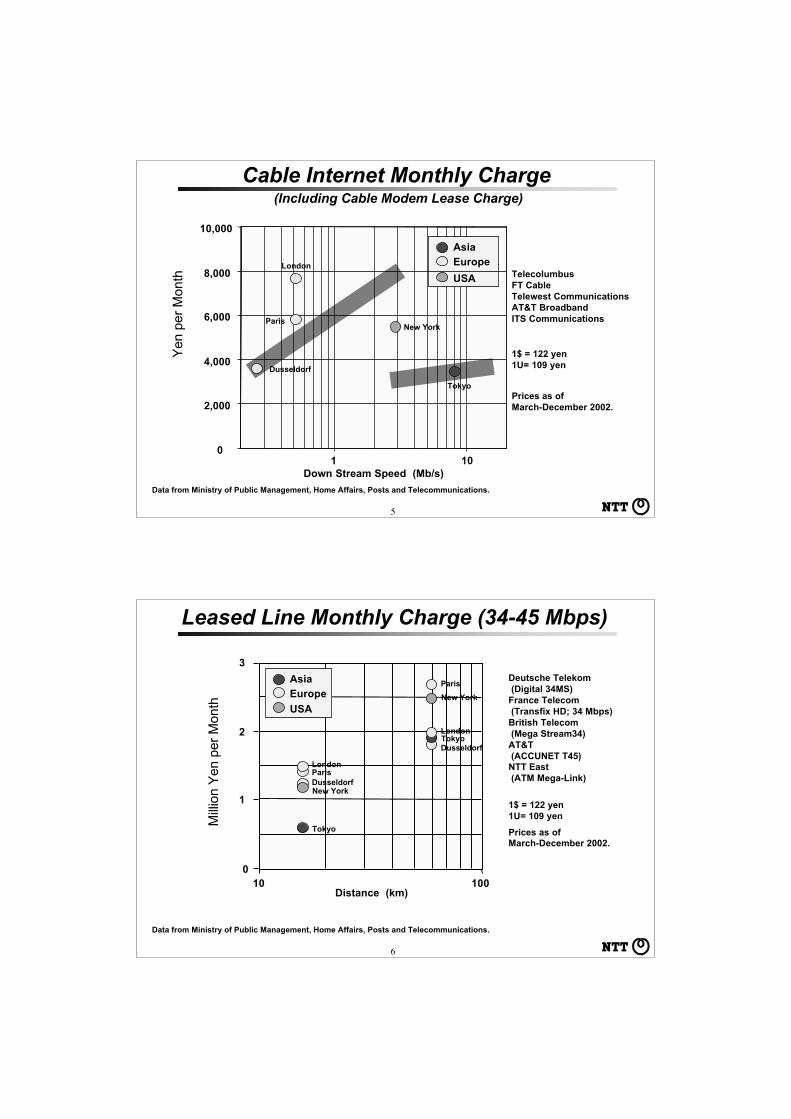
Leased Line Monthly Charge (34-45 Mbps)
Distance (km)
1$ = 122 yen1U= 109 yen
Deutsche Telekom (Digital 34MS)France Telecom (Transfix HD; 34 Mbps)British Telecom (Mega Stream34)AT&T (ACCUNET T45)NTT East (ATM Mega-Link)
Prices as of March-December 2002.
0
1
2
3
10 100
Tokyo
ParisLondon
New YorkDusseldorf
AsiaEurope
USA
Mill
ion
Yen
per
Mon
th
Tokyo
Paris
London
New York
Dusseldorf
Data from Ministry of Public Management, Home Affairs, Posts and Telecommunications.

7
New Z
eala
nd
Nether
lands
0
1
2
3
4
Switz
erla
nd
Japan
Icel
and
USANorw
ayCan
ada
Denm
ark
Belgiu
m
UK
Hong Kong
Singap
oreSw
eden
Taiw
anAust
riaFin
land
Korea
Austra
lia
0
5
10
15
20
25
Japan
Korea
Belgiu
mHong K
ongTai
wan
New Z
eala
ndSin
gaporeUSA
Canad
aAust
ralia
Nether
lands
Norway UK
Icel
and
Swed
enAust
ria
Switz
erla
ndDen
mar
kFin
land
16
40
80
Price of Typical BB Connection As a % ofMonthly Household Income, April 2003
Price Per 100 kbps of Data per Month, US $,April 2003
T. Reynolds, ITU-T Promoting Broadband Workshop, Geneva, April, 2003
%$/
100
kb/s
Price of Broadband Connection
1(0.18)
1.6(0.29)
120(21.2)
8
Reasons for ADSL High-Penetration in Japan?
1. Low Subscriber Charges Stemming From:
● Competitive Environment- Local loop unbundling for ADSL and FTTH- Collocation
● Many ADSL Operators: about 50
2. Higher Speed Systems (up to 24 Mbps)
N.B. No Financial Support from Government
9
Why is FTTH so Cheap in Japan?
1. Low Installation Cost• Ratio of Apartment Inhabitants is High; about
40%.• High population density; 70% of the land is
covered with mountain• Aerial cable is used for the last mile (no digging)
2. Strong Competition• Competition between ADSL and FTTH• Competition among FTTH operators
3. Cost-effective Systems using Ether-based MediaConverter and B-PON.
10
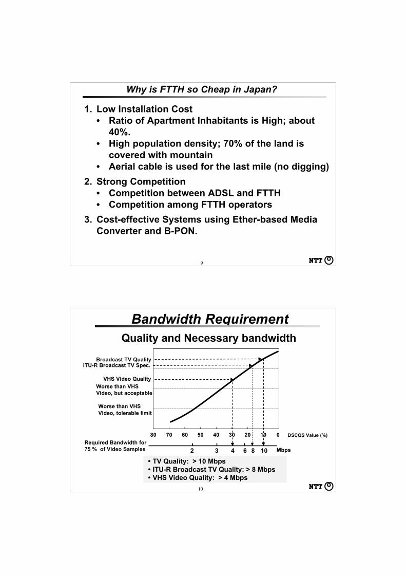
Bandwidth Requirement
DSCQS Value (%)
108642 3
01020304050607080
・TV Quality: > 10 Mbps・ITU-R Broadcast TV Quality: > 8 Mbps・VHS Video Quality: > 4 Mbps
Quality and Necessary bandwidth
Broadcast TV Quality
VHS Video QualityWorse than VHSVideo, but acceptable
Worse than VHSVideo, tolerable limit
ITU-R Broadcast TV Spec.
Required Bandwidth for75 % of Video Samples Mbps

11
Available Speed vs. Transmission Loss for ADSLM
axim
um
Do
wn
stre
am S
pee
d 12
10
8
6
4
2
0706050403020100
Mb/s 12 M type
8M type
1.5M type
25 dB
Transmission Loss between Subscriber and SP building (dB)
12
Flets ADSL 8M Type From http://www.ntt-east.co.jp/flets/misc/adspeed.html
Measured Downstream Speed for 8 Mb/s ADSL
Mea
sure
d D
ow
nst
ream
Sp
eed
Mb/s
0 10 20 30 40 50 60 Transmission Loss between Subscriber and SP building (dB)
・: # of data is 1○: # of data is 2-4●: # of data is >5
Total # of data >4,200

13
1. More than 8-10 Mbps will be required to get TV qualitystreaming video services stably, and much higher isneeded to support SHD video quality services.
2. ADSL provides several mega bit per second only forlimited users who are very near (less than about onekilometer) the service provider’s office. If the price isthe same for all subscribers, unfairness in terms ofavailable bandwidth exists. This unfairness willbecome more and more tangible when bandwidthdemanding services proliferate.
Why FTTH ?
14
P2P Communication

15Data from White Paper 2002, Ministry of Public Management, Home Affairs, Posts and Telecommunications.
Trends in Internet Usage by Purpose
: 2000
: 2002
330%170%
+260%
230%
260%
Multiple Answers Permitted, Excerpt
16
120
100
80
60
40
20
0
Mb/s
Outgoing Traffic from the University of Wisconsin to the Internet
: Napster: Others
1999 May 1999 Sept. 2000 May 2000 Sept.

17
● About 3.4 % of Internet Users (about 99 mill.)● Application Used for File Exchange (multiple answers permitted)
WinMX : 82.4 %
Winny : 22.8 %
Napster : 22.5 %
● Average Number of Downloaded Files per User is 162,
of Which 32.5% were Video.
● 45.1% of them uploaded; Published 124 Files on the
Average
Increase in P2P Traffic
P2P File Exchange Statistics in Japan Data are at June 2003.
Copyright and Moral Issues Need to be Resolved before P2P canBecome More Widely Spread. Increase in Users Will Cause SignificantNetwork Traffic Load.
18
Lessons Learned form P2P
Abrupt Generation of Large Volume of Traffic
Increase of Large File-size Traffic
Different Traffic Patterns(Up-/Down Traffic )
- Instead of 10:1(down:up), just 3(or 2):1
Number or Users Increased with the AvailableSubscriber Access Speed
Usage Increased as HD Storage Capacity withAlways-on Connections Increased (Local Storeand Replay Enhances Usage)
Peer-to-Peer is More Than Sharing Music/Video Files;It Might Create the Way to a New Business Scheme.

19
Broadband Services
20
Traffic Increase:> x 2/12 monthsFirst Stage:
Introduction ofWavelengthrouting
OADM
Phot
onic
MPLS
OXC
Phot
onic
Burst
Electrical Processing
Traffic IncreaseStemming fromNew Services:x n/12 months
Moore’s Law: x2 /18 months
Second Stage:Introduction ofSuper DWDM(>1,000 l’s)
Year Broadband andUbiquitous NW
Expansion ofCommunications Services
Enhancement of Photonic NW Services and Performance

21
Real Time VLBI Measurement System
Radio Wave from Galaxy
RX
TX
Photonic2Networks
RXTX
TXTX
VLBI: Very Long Baseline Interferometory
Usuda
Nobeyama
KSP Miura
National Astronomical Observatory
Communications Research Labs.
KSP Tateyama
Kashima Space Communications Research Lab.
NTT MusashinoR&D Center
22
Medical Network
Uses: Medical Applications, Education and Amusement
A large hospital generates 80 Gb of data each day.
Medical Applications
PublicHealthCenter
Firehouse Drugstore
MedicalInformationDatabase
Hospital
In-home Care
MedicalRecordData
!Tele-Immersion > 10 Gb/s (Database, Simulation, Rendering)!SHD Motion Picture = 6 Gbit/sec!High-Vision Motion Picture = 1.2 Gbit/sec
Education and Amusement
EducationNetwork
ElectricalLibrary
Lecturer Student
Data base
ServiceProvider
Photonic Network

23
• FedEx is already a Terabit network– thousands of disks and tapes shipped daily– jitter and delay is pretty poor– cost for shipping tape approx. 0.000001¢/byte– current cost of sending data over fiber 0.001¢/byte
(1998 CANARIE Inc.)
Photonic Network
・Light speed・Low cost(nighttime)
Transport of package media
24
Photonic Backbone Network
・immediate・low cost
Digital Cinema
QUALCOMM’s Approach Expectation for Digital Cinema - 31,000 screens (USA) - 231 major titles (1997) - Cost for printing, $700 mill. ( $22,400/screen)
Digital Cinema will Spur - increase in smaller theaters - increase in number of copies - world-wide simultaneous release
25
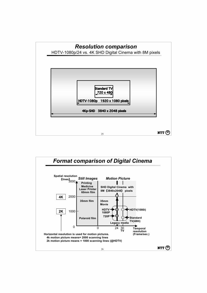
Resolution comparisonHDTV-1080p/24 vs. 4K SHD Digital Cinema with 8M pixels
HDTV-1080p 1920 x 1080 pixels
4Kp-SHD 3840 x 2048 pixels
Standard TV720 x 480
26
Format comparison of Digital Cinema
Polaroid film
35mm film
3024
60mm filmLaser Printer
PrintingMedicine
2000
1000
0
35mmMovie
HDTV1080P720P Standard
TV(480i)
HDTV(1080i)
TV
Still Images Motion Picture
0
3000
SHD Digital Cinema with8M(3840x2048) pixels
Temporalresolution(Frame/sec.)
Spatial resolution(lines)
Legacy media
Horizontal resolution is used for motion pictures. 4k motion picture means= 2000 scanning lines 2k motion picture means = 1000 scanning lines (@HDTV)
4K
2K

27
Digital Cinema Architecture Empowered by Photonic Technologies
Photonic Network275 ″ Screen3840x2048 pixels@24p, 96 Hz Refresh
Multi-format Decoder
Photonic MPLSRouter
Digital CinemaDistribution Server
300-400Mbps IPStream ofFile Transfer
35 mm FilmDigitizer
ArchiveCenter
Motion Jpeg(15:1)
G-Ether
G-Ether
28
Streaming Trials at Internet2TCP/IP based streaming experiments over large-scale, high-speed networks (1) Stable Streaming of SHD Digital Cinema (cope with long delay)
(2) Arbitration of Streaming Traffic by using MXQ (MaXimal Queuing) Mechanism
(3) Wide-Area Multipoint Live Streaming (Flexcast): Connecting 3 sites using GEMnet and Abilene (Internet2)
Yokosuka Japan (NTT Lab.), Chicago, (UIC/EVL,NWU/StarLight), Los Angeles (USC)
SHD Digital Cinema Streaming : From Chicago to L.A (3,000km) 300Mb/s
GbE
OC12/ATM
Abilene
LightReef Z4
LightReef Z4
Cisco SL6509
Traffic Monitor
NTT Server
Application Traffic MonitorDecoderUSC/ Zemekis Center
StarLightNew Route 66
Route 66
Abilene 10 GbE
<20 MbpsSunny Vale
PacificLink
NTT
GEMnet
Cisco 12404

29
Demonstration of SHD Digital Cinema in cooperationwith European Digital Cinema Forum (EDCF)
CineCitta in Rome–Famous Cinema Studio–Ministry of Culture is pushing
4K Digital Cinema in Italy
National Film Theater in London
–Testbed of EDCF is located atNational Film Theater (6/24)
–Support of DTI
30
Advances in TransportNetwork Technologies

31
• Less Service Dependent than Circuit/Flow• Grouped Circuits/Flows Serving as a Unit of Network Operation,
Design and Provisioning, Including Traffic Engineering• Object to Be Rearranged in Node and Transmission
Line/System Failure Restoration
Switch Switch
Cross-connect Path
Optical Fiber/Radio Wave
Optical Fiber/Radio Wave
Circuit
Cross-connect Path
Circuit
Role of Path
32
Switch
Higher-Order Electrical Path Cross-connect
Optical Fiber
Circuit
OpticalFiber
Higher-Order Electrical Path
Lower-Order Electrical Path Cross-Connect
Lower-orderElectrical Path
Hierarchical SDH Path Structure
ServiceAccess
Trans-Access

33
Service 1
(a) Media management by VPs
Transmission Link
Media 1
(c) QoS management by VPs
QoS 1QoS 2QoS 3
(b) Network service management by VPs
Transmission Link
Transmission Link
Media 2Media 3
Service 2Service 3
VP
VP
VP
8 7 6 5 4 3 2 1VPI
VPI VCIVCI
VCI PT CLPHEC
123456
53
OctetBit
Header
Information field
Header structure at NNI
Header Information field
5 octets 48 octets
53 octets
Cell structure
ATM Virtual Path
34
Virtual Path Benefits - Compared to Digital Path in STM -
Simplification of Interface and Node Structure
Simplification of Path Layer Architecture
Simplification of Path Accommodation DesignIn Terms of Path Hierarchy
Network Flexibility Enhancement

35
Hierarchical Path Structure
Switch/RouterFunction
Optical Path Cross-connect
Optical Fiber
Circuit/Flow
Optical Fiber
Optical Path
Electrical PathCross-ConnectFunction
Electrical Path(VP, LSP, DP)
36
Optical PathWP (Wavelength Path) and VWP(Virtual Wavelength Path)
WP 1 WP 2 WP 3 VWP 1 VWP 3VWP 2
VWP 4WP 4

37
1. Enhanced Transmission Capacity With WDM
2. Enhanced Cross-Connect Node Throughput with Wavelength Routing
3. Flexible and Progressive Transport Capacity Enhancement
4. Provision of Transport Platform(Different Degree of Transparency Can be Utilized)
5. Effective Network Protection/Restoration
Advantages of Optical Path
38
Multiplexing and Path Realization Technologies
MultiplexingTechnologies
Path Technologies
Path Identification(# of Paths/Link)
Soft/HardState Routing
PDHSDH
ATM
Packet
WDM
Digital Path(VC-1n, VC-3/4)
VP
LSP
OpticalPath
Time Position inthe TDM Frame
(< 192)
Cell header (VPI)(< 4096; NNI< 128; UNI)
Sim Label(<220)
Wavelength(<1,000)
Hard
Hard
Soft
Soft
Store-&-ForwardElectrical Processing
+Space Switch
Waveguide Router (Self-Routing)
and/orSpace Switch
Time SlotInterchange
+Space Switch
Store-&-ForwardElectrical Processing
+Space Switch

39
Label-Switching Router (LSR)
MPLS
Label Switched Path (LSP)
Egress LSRIngress LSRMPLS domain
IP Router
IP packet isencapsulated.
Label is swapped.
MPLS integrates IP and data-link layer technologies.
Removes theMPLS header.
(LabelEdgeRouter)
(Label EdgeRouter)
(LabelSwitchRouter)
40
The initial MPLS effort will be focused on IPv4. However, the coretechnology will be extendible to multiple network layer protocols(e.g., Ipv6, IPX, Appletalk, DECnet, CLNP). MPLS is not confinedto any specific link layer technology, it can work with any mediaover which Network Layer packets can be passed between networklayer entities.
MPLS provides connection-oriented (label based) switching basedon IP routing and control protocols. MPLS may be likened to a'shim-layer' which is used to provide connection services to IP andwhich itself makes use of link-layer services from L2 (e.g. PPP,ATM, Ethernet).
MPLS
A Framework for Multiprotocol Label Switching <draft-ietf-mpls-framework-05.txt> September 1999

41
Layer 3
Layer 2
IP Header
ATM
IP
VPI/VCI DLCI Shim Label
Frame Relay Ethernet
Shim Label
PPP
MPLS Labels; Label stacking and support of various media
MPLS is intended to run over multiple link layersSpecifications for the following link layers currently exist:
ATM: label contained in VCI/VPI field of ATM headerFrame Relay: label contained in DLCI field in FRheaderPPP/LAN: uses ‘shim’ header inserted between L2and L3 headers
42
MPLS Header
Layer 2 Header MPLS Header IP Packet
Label (20 bits) EXp (3) S (1) TTL (8 bits)
Label; 20 bits (4 bits for indicating how to handle labels, 16 bits for indicating FEC)Experimental (was CoS, class of service); 3 bitsStacking bit; 1 bit (indidcates the presence of a label stack; 1=last entry in label stack)Time to Live; 8 bits (same functionality as IP TTL; used to through away looping packets)
4 Bytes
★ short and fixed length★ associate to Forward Equivalent Class (FEC)
43
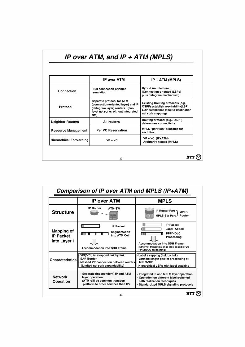
IP over ATM, and IP + ATM (MPLS)
Protocol
IP over ATM
Neighbor Routers All routers
Resource Management Per VC Reservation
IP + ATM (MPLS)
Routing protocol (e.g., OSPF)determines connectivity
Separate protocol for ATM(connection-oriented layer) and IP(datagram layer) routers (twolevel networks without integratedNM)
Existing Routing protocols (e.g.,OSPF) establish reachability(LSP),LDP establishes label to destinationnetwork mappings
MPLS “partition” allocated foreach link
Connection Full connection-orientedemulation
Hybrid Architecture(Connection-oriented (LSPs)plus datagram mechanism)
Hierarchical Forwarding VP + VC (IP+ATM)Arbitrarily nested (MPLS)VP + VC
44
Comparison of IP over ATM and MPLS (IP+ATM)IP over ATM MPLS
}Structure
Mapping ofIP Packetinto Layer 1
IP Router ATM-SWIP Router PartMPLS-SW Part
MPLS-Router
IP Packet
Segmentationinto ATM Cell
Accommodation into SDH Frame
IP PacketLabel AddedPPP/HDLC Processing
Accommodation into SDH Frame(Ethernet transmission is also possible w/oPPP/HDLC processing)
Characteristics
NetworkOperation
- VPI(/VCI) is swapped link by link- SAR Burden- Meshed VP connection between routers (Limited network expandability)
- Label swapping (link by link)- Variable length packet processing at MPLS-SW- Hierarchical LSPs with label stacking
- Separate (independent) IP and ATM layer operation (ATM will be common transport platform to other services than IP)
- Integrated IP and MPLS layer operation- Operation on different label switched path realization techniques- Standardized MPLS signaling protocols

45
☆Traffic Engineering (Path oriented)- Possibility to set-up other paths than “shortest paths”- Multiple paths between two points: Load sharing,
1 + 1, 1 : N, M : N Protection☆Very flexible because of de-coupling of forwarding and routing (forwarding decision is separated from routing
process)☆Support capabilities of VPNs and new service provisioning
- by allowing the forwarding infrastructure to remain the same while new services are built through the assignment of packets to an LSP
☆Enahanced QoS
Why MPLS?● MPLS helps scaling pubic IP networks and enhance network performances● MPLS provides network providers with means that can differentiate their services from others.
46
2
Routing G-bit Networking Tera/Peta-bit Networking
IP
ATM
etc
.SD
H
Elec
trica
lO
ptic
al
Wav
e-le
ngth
Routers basedon softwarerouting
Routers basedon hardwarerouting(ASIC)
Tbit Routers(IP v6,
HierarchicalAddressing etc.)
Routing isdone withIP only(RouterMulti-hop)
Laye
r 2La
yer 1
PhotonicMPLS
Node ThroughputEnhancement
TrafficEngineering(QoSguarantee)
IP over Optical Path
IP over ATMIntroduction ofUnderlyingTransferMechanismwhich enableseffective trafficengineeringMesh-likeconnectionis possible(Routersingle hop)
MPLS: Multi Protocol Label Switching
MPLS
Router Throughput IncreaseIP over SDH IP over WDM (SDH)
Laye
r 3
Enhancement of Networking Function
Evolution of IP transport mechanism

47
MPLS and Photonic MPLSMPLS Router
Ingress Egress
Label Switch
Ingress Egress
Photonic Router
MPLS
Photonic MPLS
l Label is added to each packet.
l Wavelength label is added to each layer 1 stream.
WP approachVWP approachWavelength Label
Optical Label Switch
Labeled PacketLabeled Packet
Label
IP Packet IP Packet
IP PacketIP Packet
48
MPLS and Photonic MPLS Cont..
IP packet
MPLS Router
IP packet
Ingress
Labeled Packet
IP packet
Egress
IP packet
Ingress Egress
Photonic Router
MPLS
Photonic MPLSl Label merge function can be realized.
l Label merge is difficult. Label stack is also difficult.
IP packet
IP packet
Labeled Packet

49
MPLS and Photonic MPLSLSP 1
LSP 2
LSP 3
LSP 1
LSP 2 OLSP 1
MPLS-Router
Photonic MPLS-Router
OLSP 1
LSP1 and LSP 2 are accommodated within LSP 3.
LSP1 and LSP 2 are accommodated within OLSP1.
MPLS-Router MPLS-router pert multiplexes LSP1 and
LSP2 and connects to OLSP1.
50
Comparison of Electrical MPLS and Photonic MPLS
Electrical MPLS Photonic MPLS
Path Label Switched Path(Label is attached to each packet)
Optical Path(Label is attached to data stream)
Label Merge Yes Difficult
Label Stack Yes Difficult
Path State Soft Hard
# of Paths/LinkCan be very large
(220=1,048,576) Limited ( < 1,000)
Path Bandwidth Any Usually fixed and large (Gb/s)
Label Swapping Yes Yes (with wavelength conversion)
No (without wavelength conversion)
Hit-less RouteChange Yes (Make-before-break) No (possible only at electrical level)

51
PTSPhotonic (MPLS) Plane
IP (MPLS) Router
Photonic (MPLS) Router
MPLS Plane
AdministrationDomain
Photonic MPLS and MPLS hierarchical architecture
52
Best Effort(Connectionless) Engineered QoS
(Connectionless on Connection Oriented)
Guaranteed QoS(Connection Oriented)
ATM XC/Switch
MPLS RouterIP Router
Big IP RouterBig MPLS
Router
Photonic MPLS Router
Thro
ughp
ut (N
etwo
rk S
cala
bility
)
Photonic MPLS Router
IP over ATM
OXC/OADM
Digital XC

53
OXCs and Photonic MPLS routers co-exist?
Yes, each has its own application.
Photonic MPLS routers are regarded as the ultimate inintegrated router systems.OXCs create optical platform on which different transfermode services can be provided.
Criteria of the Selection - Services (IP only or IP and other services, ex. Lambda service?) - Ownership (Are IP routers and OXCs and Transmission Equipment owned by the same provider?) - Segmentation of Network Management
54
This document describes extensions to MPLS signalingrequired to support Generalized MPLS. GeneralizedMPLS extends MPLS to encompass time-division (e.g.SONET ADMs), wavelength (optical lambdas) andspatial switching (e.g. incoming port or fiber to outgoingport or fiber). This document presents a functionaldescription of the extensions.
Generalized MPLS - Signaling Functional Description
Draft-ietf-mpls-generalized-signaling-00.txt
Genralized MPLS
GMPLS signaling: Extensions to MPLS signaling required to supportFour switching classes in GMPLS.
- GMPLS CR-LDP extensions- GMPLS RSVP-TE extensions

55
Enhancement of MPLS for GMPLSSupport different types of switches; packet-switchcapable, layer 2-switch capable, TDM capable,lambda-switch capable, fiber-switch capable.
A new Link Management Protocol (LMP) that runsbetween adjacent nodes and is used for both linkprovisioning and fault isolation.
Enhancement of OSPF/IS-IS routing protocols toadvertise availability of optical (and other)resources in the network.
Enhancements to RSVP/CR-LDP signaling protocolsto allow a label-switched path to explicitly specifiedacross the optical core.
Optical label switched path is bi-directional.
56
IP MPLS GMPLSMPLS-TE
Connection-lessConnectionOriented LSP(LSP, VP/VC,DLCI)
MPLS+TEExtensions
Multi-Layer LSPs+ TE Extensions
Connection
Routing/Forwarding
Hop-by-HopPacket Routing
Label Switchingwith LabelSwapping
MPLS+ExplicitlyRouted TE-Tunneling
Explicitly RoutedTE-Tunneling withMulti-layer LSPs
Control andData Plane Coupled
LogicallySeparated
Logically/PhysicallySeparated
Logically/PhysicallySeparated
Routing
Distributed IGPProtocol forRouting andPath Calculation
Hop-by-HopRouted Path:OSPF, ISIS,BGP-4
Constrained-based Routing:OSPF-TE, ISIS-TE, BGP-TE
Extensions toHandle Multi-LayerTE and Each LayerPath PeculiaritiesLink managementprotocol (LMP)
Signaling LDPRSVP-TE
CR-LDP,RSVP-TE
CR-LDP-EXT,RSVP-TE-EXT
Evolution of IP-oriented Network Technologies
IGP, RSVP
(Distribute Topology Information Only)
57
Fundamentals of Photonic Network
58
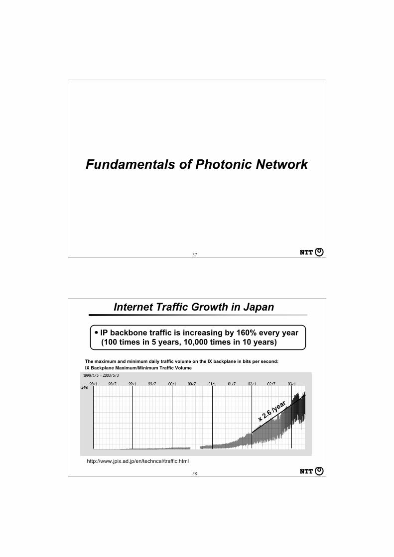
IX Backplane Maximum/Minimum Traffic Volume
The maximum and minimum daily traffic volume on the IX backplane in bits per second:
http://www.jpix.ad.jp/en/techncal/traffic.html
・IP backbone traffic is increasing by 160% every year (100 times in 5 years, 10,000 times in 10 years)
Internet Traffic Growth in Japan
x 2.6 /year

59
x 4.7 /year
The other IX (JPNAP) has higher traffic growth rate by370% every year .
60
Monthly aggregate traffic at AMS-IX, Nov 2001 - Jan 2003
By Erik Radius, SURFnetON*VECTOR photonics workshop, San Diego, February 3-4, 2003
x 2.6 /year
Internet Traffic Growth in Europe

61 61
・Traffic growth in NA was 85 % in 2002.
Internet Traffic Growth in North America
62
Characteristics of IP Traffic
Rapid and Unpredictable Traffic Growth- Data traffic grows very rapid- Data traffic demands are unpredictable
in terms of capacity and location.- Traditional capacity planning methods
for voice traffic are rendered obsolete.
Unpredictable Traffic Pattern Change
Distance Insensitive
Minimum Intervals in Service Provisioning- Need to be attained in response to the
unpredictable traffic demand.
Slow/Steady and PredictableTraffic Growth
Predictable Traffic Pattern Change
Most calls Terminate within LocalArea
Service Provisioning can be basedon Planning
IP Traffic Voice Traffic

63
Connection distance (km)
Frac
tion
of to
tal tr
affic Voice traffic
(744 k m average)
Internet traffic(2729 k m average)
0.7
0.6
0.5
0.4
0.3
0.2
0.1
0
0 to 500
1000 to 1
500
3000 to 3
500
7000 to 7
500
4000 to 4
500
6000 to 6
500
2000 to 2
500
5000 to 5
500
USA Connection Capacity Statistics
64From OFC2002 Short Course, Optical Internetworking Architecture, by Joseph E. Berthold, March, 2002
Traffic Model in North America
Total Generated Traffic = about 3 Tb/s- No Relation to Network Topology
Distance Bandwidth Product = about 10M Gb/sec-km- Obtained by Mapping Demands to Physical Topology- Parameter more Related to Capital Cost
Maximum Transmission Capacity = 1 Tb/s per Fiber (10Gb/s x 100l)
Maximum Node Throughput = 50-250 10G port

65
DCS 3/1 or Patch Panel
Patch Panel
Metro Inter-Office Ring; 622 M, 2.5 G
DCS 3/1 or Patch Panel
DCS 3/3 or Patch Panel
DCS 3/3 or Patch Panel
Some Hundreds of Rings Exist in a Large Metro Network
About 10 Nodes (About 10 Offices/Node)
Metro-Core Office
About 10 Nodes (About 100 Rings)
Tens of rings
Metro-Core Ring; 2.5 G
Long-Haul Ring; 2.5 G/10G
Partial-Mesh Connection for IP Core Network
WDM TransmissionEquipment is Omitted
Network Configuration Example in North America
66
Link Distance Distribution
21%
37%
13%
8% 8%6% 5%
3%
0%
5%
10%
15%
20%
25%
30%
35%
40%
0-20
0
200-
400
400-
600
600-
800
800-
1000
1000
-120
0
1200
-140
0
1400
-160
0
1600
-180
0
Link Length (km)
Coun
ts (%
)
Circuit Length Distribution
9%
20%
16%
12% 12%
15%
9%
3% 3%
0%
5%
10%
15%
20%
25%
0-10
00
1000
-200
0
2000
-300
0
3000
-400
0
4000
-500
0
5000
-600
0
6000
-700
0
7000
-800
0
8000
-900
0
Circuit Length (km)
Coun
ts (%
)
Link Distance and Circuit Length Distribution in North America (40 node Model)
From J-K Rhee et al., Proc. SPIE, ITCom 2002, vol. 4872
> 90%

67From A. Solheim, Business Briefing, World Markets Research Center
Link Distance and Circuit Length Distribution in Europe
68
Wavelength Routing on Photonic SuperhighwayWDM + (electrical) IP Router
Photonic MPLS
Existing Network
Photonic Network
WDM LinkIP Packet
IP Router
PTSWavelength Routing
IP Router
Wavelength Path
WDM Link
Traffic Jam at Node

69
Path and Round Trip Time Measurements
June 1998
http://www.caida.org/outreach/presentations/nanog9806/
Internet Hop Distance Distribution
70
End-to-End Node Cost Reduction
End-to-End node cost ratio“IP over photonic” to “IP over WDM”
PTS
WDMLT
Intermediate nodes
• IP over Photonic
• IP over WDM- 2.5 Gbit/s IP router I/F (OC-48c or STM-16)- 20 Gbit/s transmission (2.5 Gbit/s • 8 l)
Cost ratio per 2.5-Gbit/s capacity; PTS : IP router : WDM-LT
3.5 : 1.5 : 2.0
3.0 :0.75 : 2.0
1 2 3 4 5 6 7 8 9 10
1.0
0.8
0.6
0.4
0.2
Number of intermediate nodesIntermediate nodes
IP Router
IP Router
Edge node Edge node
Edge node Edge node

71
Comparison Between Ring and Mesh Network
Distance 1
Total Link Length for Ring Network Architecture = 32Total Link Length for Mesh Network Architecture = 10
Ring Network Transmission Cost/ Mesh NetworkTransmission Cost = 32/10 =3.2
Distance 1
72
Comparison Between Ring and Mesh Networks
2/4 Fiber Ring Architecture Mesh ArchitectureMinimum planning. Add capacityas needed (Pay as you growsolution). Hot-spot bandwidthupgrade.
Adaptability to dynamictraffic patterns (cannotplan 10 years anymore;IP traffic is unpredictable.)
Total throughput must be pre-planned and installed.
Bandwidth Scalability Limited (two fiber to four fiber up-grade and
multiple ring interconnection).
Controlled and managed growthis possible.
Network Scalability Limited (multiple ring arrangement).Controlled and managed growthis possible.
Restoration Speed - 50 ms < 1 s
Network Management Simple More complicated
Network ResourceUtilization
HighLower
Adaptability to distance-insensitive traffic pattern(internet traffic).
HighLow

73
1975 1980 1985 1990 1995 2000
WDM, OTDM
WDM
ETDM
ETDM
10,000
1,000
100
10
1
0.1
0.01
Tra
nsm
issi
on
Cap
acit
y ( G
bit
/s)
Doubling Every Year(traffic increase)
1,000
100
10
1
0.195
10,000
90 2000
CiscoAvici
Cisco
Cisco
Sys
tem
Th
rou
gh
pu
t (
Gb
/s)
Cisco,Pluris
Juniper
★ Server Bottleneck ★ Node Throughput Bottleneck
x2 /18months (Moore’s Law)
Traffic, Transmission Capacity, and Node Throughput
Traffic Increase Rate≒Transmission Capacity Increase> Router/Server Throughput Increase (Moore’s Law)
Year
Electrical Router
Doubling Every Year(traffic increase)
74
Photonic Network Technologies (OXC, Photonic MPLS Router)
Distributed Server Arrangement+
High-speed Networking among Servers/Routers
+Traffic Engineering(MPLS/GMPLS)
Cut-Through of Electric Routers(Introduction of Optical Path)
Role of Photonic Network Technologies
★ Server Bottleneck ★ Node Throughput Bottleneck
Traffic Increase Rate≒Transmission Capacity Increase> Router/Server Throughput Increase (Moore’s Law)
75
Path Speed(Gb/s/path)
Co
st/P
ort
OXC
EXC
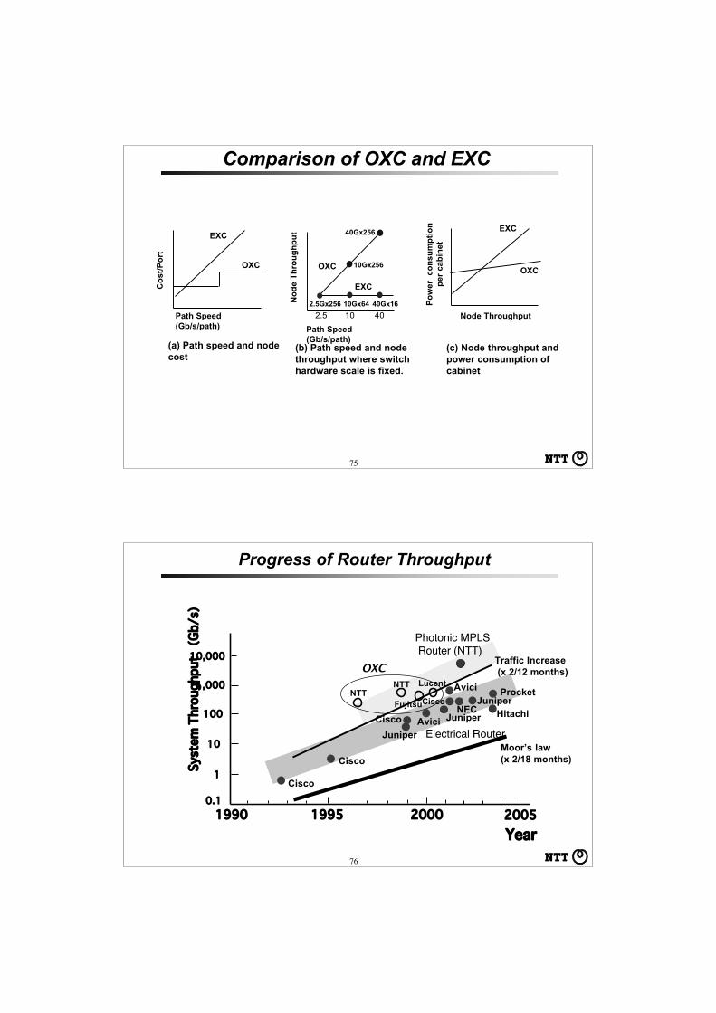
(a) Path speed and nodecost
No
de
Th
rou
gh
pu
t
(b) Path speed and nodethroughput where switchhardware scale is fixed.
2.5 10 40
2.5Gx256 10Gx64 40Gx16
10Gx256
40Gx256
Path Speed(Gb/s/path)
OXC
EXC
Po
wer
co
nsu
mp
tio
np
er c
abin
et
EXC
OXC
Node Throughput
(c) Node throughput andpower consumption ofcabinet
Comparison of OXC and EXC
76
1,000
100
10
1
0.1
1995
10,000
1990 2000
Avici
Cisco
Cisco
Juniper
NTTNTT
CiscoFujitsu
Lucent
Juniper
Avici
JuniperHitachi
Procket
CiscoNEC
2005
Moor’s law(x 2/18 months)
Traffic Increase (x 2/12 months)
Year
System Throughput (Gb/s)
Progress of Router Throughput
Photonic MPLS Router (NTT)
Electrical Router
OXC

77
Williams Communications, ECOC 2002
Distribution of Number of Circuits for Backbone Carrier
DS1
DS 3
OC-3OC-12 OC-48
35 %
45 %
13 %
3 % 1 %
Number of Nodes: 16Number of Links: 29Node Degree: 3.6
78
Photonic Network Architecture

79
OADM : Optical Add/Drop MultiplexerOXC : Optical Cross-connect
OXC
l1
lN・・
OADM
l1 l2 l1 l3
l2l3
l1 l2 l1 l3
l2l3
~10
0Gb/
s1T~
10Tb
/s>1
0Tb/
s
Year
Evolution of Photonic NetworkTransport ofInformation Block withWavelength Label
Distributed Controlnetwork withPhotonic MPLS
CentralizedControl Mesh-type Networkwith OXC’S
OADM RingNetwork
Point-to-Point WDMTransmission
PhotonicMPLS Router
IP Routing
WavelengthRouting
IP Packets aremapped withinWavelengthLabeled BitStream
Photonic Router
Dyna
mic
Con
trol o
f Wav
elen
gth
Stat
ic W
avel
engt
hO
pera
tion
80
Photons and Electrons are Very Different
Both Photons and Electrons have the nature of a particleand of a wave, but they are very different.
Photons usually behave like a wave. - Photon has no mass. - Photon has no charge.Electrons usually behave like a particle. - Electron has mass. - Electron has charge.
A crucial difference is the degree of susceptibility inregard to interacting with others.There is no basic optical functional device equivalent tothe transistor.

81
Characteristics of Photons and Electrons
Is it possible to bend the direction of photon propagation in free space?
Yes, but huge mass is necessary: The mass of the sun can bend light by 1.74second; Einstein’s Theory of Relativity.
1.74’’
If dielectric constant is changed, direction of light propagation can be changed.
Dielectric constant can be changed and controlled by using, - mirror and mechanical means - electro-optic effect - thermo-optic effect, etc.
82
Characteristics of Photons and ElectronsIs it possible to confine/store photon?
Yes, but huge mass -40 million times that of the sun- is necessary to create aBlack Hole. But can not get photon back out of black hole.
No Optical Capacitor.
Is it possible to slow down photon propagation speed?
Yes, but at almost zero degree.
300,000 km/sec at normal temperature
~0 km/sec at almost 0 Kelvin

83
0.5 mm5 mm
10 mm
40 k cell/chip1 cell @ 10 Gb/s
8.5 m
v=6x10⁻⁴ mm3/cell
V=100 mm3/cell >105 v
Bare fiberStraight Line
Bare fiberCoiled 6 cm
125 mmf
V= 16000 mm3/cell >107 v
Semiconductor Memory(S-RAM)
Optical Fiber Delay Line
Volume of Memory
Si Memory Chip
84
10
100
1,000
10,000
100,000
1994
1995
1996
1997
1998
1999
2000 2001
10,000
100,000
1,000,000
155
620
2500Ce
ll Bu
ffer p
er 1
50 M
b/s
Path
Spe
ed
Cell
Buffe
r per
Lin
k
Year Link Speed (Mb/s)
A
B
(Not a technical limit)
Available Cell Buffer per Link in ATM Systems

85
IP over ATM
ATM XC WDM LT
MPLS (IP plus ATM)WDM LT
IP over Optical Path
WDM LTOXC
Photonic MPLS
WDM LT
IP over Digital Path
Scalability Global address IP signaling (distributed control)
Traffic engineering(Introduction of paths)Node throughputenhancement (Cut-through)
Large capacitytransmission
NecessaryAttributes
Photonic MPLSRouter
IP Router
MPLS Router
IP/MPLS Router
IP/MPLS Router
IntelligentDigital XC
IP Core Network Configuration
86
MPLSRouter
OXCOXC
SDH
SDH
GMPLS
SDHSDH
GMPLS
Distributed Control
Photonic MPLSRouter(Integration ofIP router andOXC function)
Optical PathPlatform(OXC/OADM:different transfermode servicesare supported)
ControlSystem (router-based approach)
Peer modelOverlay model (in case of centralized control;distributed control is also possible.)
Centralized Control(carrier oriented approach)
MPLSRouter
IP control plane
SDH network control plane
Optical transport networkcontrol plane(centralized/distributed)
IP-based control plane
IP router control plane
MPLSRouter
PhotonicMPLS2Router
PhotonicMPLS2Router
MPLSRouter
IP and photonic layer control
Different Service Network Architecture

87
Illustration of Global Network Architecture- Centralized and Distributed Functional Allocation Schemes -
Carrier Class NetworkPlatform
OXC, OADM
LimitedQoSNetwork
NetworkManagement(Policy basedControl)
NetworkControl(Signaling)
NetworkElement &NetworkElementOperation
DistributedCentralized
Distributed
Distributed
Centralized
Photonic MPLSIP Centric Network
88
Control Plane Drivers
– Reduce operational and capital expenses• More intelligence at the NEs can reduce manual intervention and
reduce operational cost• Open standard based products increase competition and drives cost
down• Convergence of different layers can cut both capital and operational
costs
– Move from voice to data dominated traffic• Traffic is more dynamic and difficult to predict and transport layer
needs to be more agile• As the transport network becomes more dynamic, and number of
elements and connections increase, distributed control will be moreeffective

89
Photonic MPLS Router
90
1
2
M
1 2 N
M×1Optical Coupler
1×2 Optical Switch
MEMS(OFF)
MEMS(ON)
DC-SW
3D-MEMS SW2D-MEMS SW
3-stage Clos
N×2NSW
M×MSW
N×2NSW
M×MSW
N×2NSW
M×MSW
2N×NSW
2N×NSW
2N×NSW
Output
Different Switch Architecture
Inp
ut
Co
llim
ato
r
Inp
ut
Output Collimator
Substrate
Output Collimator
Input Collimator Mirror Array
Mirror Array

91
1 x 2(1) DC - SW N2 / L
2 x 2(2) 3 stage Clos
2 x 2(3) X-bar
N2 / L
N2 2 N2
2 N3/24 2 N3/28
l
O C
M×NDC-SW
(1)
1
l2
1lM
2
N
W-DMUX
W/C
W/C
W/C
W/C
W/C
W/C
W/C
W/C
W/C
●●●
●●●
●●●
●●●
M×NDC-SW
(2)
M×NDC-SW
(N)
O C
O C
1
2
N
W-TdW-Td
W-TdW-TdW-Td
W-Td
W-TdW-Td
W-Td
S-TdS-Td
S-TdS-TdS-Td
S-Td
S-TdS-Td
S-Td
1
2
N
1
2
N
M
NM x NMsinglespaceswitch
W-Td
W-Td
W-TdW-Td
W-Td
W-TdW-Td
W-Td
W-Td1
2
N ●●●
M×LSW(1)
N×NSW(1)
L×MSW(1)
(2) (2) (2)
(N ) (L) (N )
1
2
N
λ1
λM
S-Td
S-Td
S-TdS-Td
S-Td
S-Td
S-Td
S-TdS-Td
●●●
●●●
●●●
●●●
●●●
●●●
●●●
●●●
●●●
●●●
●●●
●●●
●●●
●●●
●●●
●●●
●●●
●●●
●●●
●●●
Necessary Hardware of Switch Architectures
Architecture Element SwitchNecessary Numberof Element Switch
Necessary Numberof Equivalent 1x 2Switches
(1) DC - SW (2) 3 stage Clos (3) X-bar
92
Switch Scale, N (N x N)
Nec
essa
ry N
um
ber
of
Un
it S
wit
ches
Necessary Hardware of Switch Architectures
1
10
100
1,000
10,000
100,000
1,000,000
10 100 1000
1x2 S
W
1xN SW
1x2 S
W
2x2 SW
1x2 S
W
1
Switch Scale, N (N x N)
Nec
essa
ry N
um
ber
of
Eq
uiv
alen
t 1x
2
Sw
itch
es
1
10
100
1,000
10,000
100,000
1,000,000
10 100 1000
DC-SW (8λ)DC-SW (32λ)3-stage Clos2D-MEMS (single stage)
3D-MEMS
DC-SW (8λ)DC-SW (32λ)3-stage Clos2D-MEMS (single stage)
3D-MEMS

93
0.00
0.10
0.20
0.30
0.40
0.50
0.60
0.70
0.80
0.90
1.00
0.00 0.02 0.04 0.06 0.08 0.10
t/T(MTBF)
Prob
abili
ty
No. of failed mirrors24
16
8
0.00
0.10
0.20
0.30
0.40
0.50
0.60
0.70
0.80
0.90
1.00
0.000 0.005 0.010 0.015 0.020 0.025
t/T(MTBF)
256×256 SW 1024×1024 SW
MTBF:MEMS mirror average life time
If the system life time is specified as 10 % failure of all mirrors, then about
50 % of systems show a life time of just 1.8 years when the MTBF of each mirror
including the feedback control system is 20 years.
Very reliable 3-D MEMS mirrors and control system are required.
Switch Reliability
Prob
abili
ty
0
No. of failed mirrors24
16
8
0
94
1X2 Optical Switch
1 2 n
12
m
OC OC OC
DC-SW: Delivery and Coupling SwitchW-DMX: Wavelength DemultiplexerOA: Optical AmplifierOC: Optical CouplerPLC-TOSW: Planar Lightwave Circuit -Thermo-optic Switch
OA OADC-SW
W-DMX
OCFiber Line 1
Fiber Line 2
Fiber Line N
DC-SW
DC-SW
DC-SW architecture
DC-SW board
PLC-TOSW
Optical Cross-Connect Architecture
Link Modular Unit
Link Modular Unit
Link Modular Unit
OPXC Architecture

95
PLC-Switch
Silicon Substrate WaveguideCore
Cladding
Thin Film Heater
PLC: Planar Lightwave Circuit using Silica-based Waveguides
Ref.: T.Goh et al., Proceedings of SPIE, vol.4582, pp.49-56, APOC 2001, Beijing China.
Mach-Zehnder (MZ) 2x2 TO Switch
0 10 20 30 40Time (msec)
Applied Power
Optical Output
ON OFF ON
0.35 W-0.5 W
2 ms
Switching Response
96
Photonic MPLS Router Architecture
OXC
PAD
Photonic Router Hardware
Single ChannelLinks (UNI)
NNI : Network Node InterfaceUNI : User Network InterfacePAD : Payload Assembler/Disassembler
(UNI from/to NNI converter)NE-Mgr : Network Element Manager
(Photonic router software)DCC : Data Communication ChannelOSC : Optical Supervisory Channel
OpticalRepeater
Uni-directionalWDM Links
(NNI)
NE-Mgr
DCC over OSC
IP packetIP packet
Ingress
C ontrolmessage

97
MPLSRouter
LRU
Optical amplifier
WavelengthDemultiplexer
Optical coupler
DWDM transmission fiber
Opticalswitch
IP router/Ethernet switchConnection fiber
Wav
elen
gth
con
vert
er
IP Controller MPLS Controller
MPlS Controller Photonic router network manager
PhotonicMPLSrouter
Manager
Opticalamplifier
DWDM transmissionfiber
IP router/Ethernetswitch Connection fiber
Co-operationbetween OXCand MPLSrouter.
Optical switchesfabricated byPLCtechnologies.
Dynamic opticalpath setup/tear-down.
Configuration of Photonic MPLS Router
98
Outlook and Specifications of Photonic MPLS Router
Item
Throughput
Systemthroughput
UNI
Optical switcharchitecture
Optical switch
Wavelength band
Optical channelspeedNumber ofwavelengths
Number of fiberports
Total switch scale
Scalability
MPLS routerscalability
Specifications
More than 5Gpps (Obtained withwavelength routing and MPLS router)
Maximum 2.56 Tbit/s
POS, ATM, GEther, etc.
Delivery and coupling type
Planar Lightwave Circuit (PLC)thermo-optical switch
1550 nm band (C-band)
2.5 Gbit/s (up gradable to 10 Gbit/s)
32 per fiber
8 input /output pairs (fiber port canbe added one by one)
256 x 256 channels
T h e n um ber of av a ilable o p t i c a lchannels is expandable up to 256, with 8wavelengths’ modularity (each switchmodule accommodates 8 wavelengths.)
Maximum number of available POSinterface is 128. Consists of one totwenty MPLS routers.

Page 99
Part II : Photonic Network Control and Management
• Photonic Network Control and Management Overview
• Photonic Network Architecture Overview• IP over Photonic Network Architecture
Overview• MPLS, GMPLS (MPLambdaS), and ASON• GMPLS protocols• GMPLS management• Interoperability Test Events of Photonic
Network Control
Page 100
Outline
• Photonic Network Control and Management Overview– Target Applications– Standardization Partner-ship
• Photonic Network Architecture Overview• IP over Photonic Network Architecture Overview• MPLS, GMPLS (MPLambdaS), and ASON• GMPLS protocols• GMPLS management• Interoperability Test Events of Photonic Network
Control

Page 101
Target Photonic Network Applications
• Traditional Photonic Network(for Telephone Network Backbone)
– Provisioning Base• Centralized NMS base
– Centralized Control Plane (C-Plane)– Centralized Management (M-Plane)
• New Photonic Network(for Data Network Backbone)
– Dynamic/Adaptive Network– Distributed C-Plane– Centralized M-Plane
Page 102
Network Reference Model
• Transport Network is constructed with 3 planes.– Data (or Transport) Plane– Control Plane– Management Plane
Control Plane
Data PlanePE
PE
PE
PE
PE
PE
UNIUNI
Management Plane
CICI
CMICMI MIMI
CECE
CE: CustomerCE: Customer’’s Equipment, PE: service Providers Equipment, PE: service Provider’’s Equipments Equipment

Page 103
Service Provider A Admin Domain
UNI E-NNI (b)
Service Provider B Admin Domain
Domain A1 Domain A2
E-NNI (a)
I-NNI
I-NNII-NNI
Provider A has divided network into multiple control domains
(e.g., vendor, geographic, technology, business unit, etc.)
Provider B’s network is a single
control domain
UserDomain
User-Network Interface (UNI):operations between user and service
provider control domains
Exterior Network-to-Network Interface (E-NNI):
inter-control domain operation.(a) multi-domain operation for a
single service provider(b) multi-domain operation among
different service providers
Interior Network-to-Network Interface (I-NNI):
intra-control domain operation
Network-to-Management Interface (NMI):
operations between management systems and service provider administrative domains
Fundamentals - Reference Points
firewall
firewall
L2/L3
L2/L3
LoadBalancer
LoadBalancer
Page 104
Traditional (Telephone Network)
• Centralized network operation and management with Network Management System (NMS) located in the network operation center (NOC).
– Labor-intensive processes• Error-prone, slow, and high operations costs• Rapid provisioning or network reconfiguration for resource optimization is
difficult (if needed).– There is no clear distinction between C-Plane and M-Plane.
Every action flows through the central NMS.• Limited scalability, visibility and manageability
Data PlanePE
PE
PE
PE
PE
PE
UNIUNI
CI & MI
NOC
CE CE
NMS C+M C+M -- PlanePlane

Page 105
New (for Data Network)
Control Plane (distributed)
Data PlanePE
PE
PE
PE
PE
PE
UNIUNI
CICI
CMICMI
MIMI
• Intelligent Photonic Network– M-Plane (NMS) and C-Plane are separated.– Neighbor Discovery– Routing/Topology Dissemination– Connection Signaling
• Automated Processes, Scalability, Robustness, Efficiency
NMS (monitoring)MM--PlanePlane
Page 106
Intelligent Photonic Network Foundations
• Protocol Functions– Discovery
• Neighbor and link identity and characteristics
– Routing/Topology Dissemination• Network topology and resource availability
– Connection Signaling• Automated provisioning and failure recovery
• Concepts endorsed by every standards body– ITU-T, IETF and OIF

Page 107
Standardization Bodies and Forums
ITUITU International Telecommunication UnionInternational Telecommunication UnionIETFIETF Internet Engineering Task ForceInternet Engineering Task ForceOIFOIF Optical Internetworking ForumOptical Internetworking ForumTMFTMF TeleManagementTeleManagement ForumForum
ASONASON MPLS, MPLS, GMPLSGMPLS
Optical UNI/NNIOptical UNI/NNI
Focused in this tutorial
NMSNMS
Page 108
• Different focus– ITU focuses on architecture
• ASON architecture– IETF focuses on building blocks
• GMPLS protocol specs.– OIF focuses on applications and interoperability
• Implementation Agreements (IAs) and Interoperability Test Events
• Common goal: better photonic networking • Recognized need for coordination
ITU vs. IETF vs. OIF
L. Ong, “Optical Control Plane Activities in IETF and OIF”, ITU-T Workshop on IP/Optical Chitose, Japan, 9-11 July 2002

Page 109
Major Work Areas of ITU (ITU-T SG15)
• Optical Transport Network (OTN) structure – Automatic Switched Optical Network (ASON)– Architecture and interfaces for the OTN– Optical (Photonic) Cross-Connect and Switch functions– Network management and control
• OTN technology (terrestrial and submarine)– Coarse and dense WDM, STM-256 (40Gb/s) signal
channels– Optical components & amplifiers (e.g. tunable filters)– Fiber characteristics, more channels/fiber– Transmission technology (Soliton/RZ), long reach
Page 110
OTN Technology Standardization Work Plan
• Standardization areas covered– OTN Technologies (variety of aspects)– SDH & SONET
• Next Generation data centric transport network– Generic Framing Procedure (GFP)– Virtual Concatenation (VCAT)– Link Capacity Adjustment Scheme (LCAS)
– OTN Transport Plane (D-Plane)– ASON Control Plane (C-Plane)

Page 111
• IETF’s Traditional Focus– The Internet: IP and IP Services – routing,
transport, applications, security & management• Sub-IP Area
– Coordinates activities below the IP layer, esp. MPLS/GMPLS and IP over Optical.
IETF Optical Standards
IESGIESG
Transport RoutingApp., General, Internet, OAM,
SecuritySub-IP
sigtran pwe3 ospf idr ipo ccamp
ipo : IP over Opticalccamp : Common Control and
Measurement Plane
IESG : The Internet Engineering Steering Group
Areas
WGs
Page 112
IETF GMPLS: History
• How did GMPLS start?– Outgrowth of MPLS - IP traffic engineering work – “Generalized” protocols for label-switched path
creation• Fiber switching• Wavelength/Waveband switching• Time slot switching (SDH/SONET)
• Possible Architectures – Flat network – routers and optical systems fully
peered (Peer Model)– Hierarchical network – routers are optical clients
(Overlay Model)• Scope
– Support of IP networking over optical transport– Non-IP-related use of GMPLS is out-of-scope

Page 113
Optical Internetworking Forum (OIF)
• The only industry group bringing together professionals from the data and optical worlds.
• Open forum– international– carriers– component and systems vendors– testing and software companies
• Launched in April of 1998 with an objective to foster development of low-cost and scaleable internet using optical technologies.
• Mission: To foster the development and deployment of interoperable products and services for data switching and routing using optical networking technologies.
Background and MissionBackground and Mission
Page 114
OIF Focus
• Low-cost Scaleable Optical Internetworking– IP-Over-Switched Optical Network Architecture– Physical layer
• Low-cost optical interfaces between networking elements• Standard device level electrical interfaces for low-cost
systems– Control layer interoperability between data and
optical layers• Dynamic configuration using IP signaling and control
mechanisms• Accommodate legacy network under the new
physical and control layer mechanisms

Page 115
OIF Current Work
• UNI 1.0 (now developing 1.0R2)– Focus on SDH/SONET environment– Approved, interoperability events sponsored at
SuperComm2001 and OFC2003
• UNI 2.0– Extensions for, e.g., Ethernet environment, multi-homed
access, non-disruptive connection modification, enhanced security
• NNI– Interface between domains; but intra-carrier E-NNI (a)– InterDomain signaling– InterDomain routing (new hierarchical routing)
Page 116
Outline
• Photonic Network Control and Management Overview
• Photonic Network Architecture Overview– New Optical Layer Hierarchy (OTN) and SDH/SONET (Pre-
OTN)• IP over Photonic Network Architecture Overview
– Peer Model, Overlay Model• MPLS, GMPLS (MPLambdaS), and ASON• GMPLS protocols• GMPLS management• Interoperability Test Events of Photonic Network
Control

Page 117
SDH and SONET
• Good for aggregating small flows into a fat pipe (First developed for telephone networks)
• Electric endpoints, strong protection, troubleshooting functionality
SDH: Synchronous Digital Hierarchy (ITU)SDH: Synchronous Digital Hierarchy (ITU)SONET: Synchronous Optical SONET: Synchronous Optical NETworkNETwork (ANSI)(ANSI)
SDH/SONETSTM-1 156 Mb/sSTM-4 622 Mb/sSTM-16 2.5 Gb/sSTM-64 10 Gb/sSTM-256 40 Gb/s
VC-350 Mb/s
VC-11
1.5 Mb/s
VC-4VC-4-4c
600 Mb/s
150 Mb/s
VC Virtual ContainerSTM Synchronous Transport Module
Page 118
SDH Standardization
Network Architecture(G.803, G.805)
Structures and Mappings(G.707)
Physical Layer(G.957, G.691)
Equipment Functional Spec.(G.783, G.806)
Equipment Management(G.784, G.7710)
Information Model(G.774 Series)
Protection Switching(G.gps, G.841, G.842)
Laser Safety(G.664)
Data and Signaling Communications Network
(G.7712)
Jitter and Wander Perf.(G.825)
Error Performance(G.826-829)
Ghani Abbas and Stephen Trowbridge, “OTN Equipment and Deployment in Today’s Transport Networks”, ITU-T Workshop on IP/Optical Chitose, Japan, 9-11 July 2002

Page 119
Optical Transport Network (OTN)
• Metro Access• SDH metro ring applications• Multi-Service Provisioning Nodes - combining data and SDH
• Metro Core• SDH ADM metro ring and mesh application• Optical add/drop multiplexers (proprietary)
• Long Haul/Ultra Long haul• SDH ADM rings and line systems• DWDM line systems (proprietary)
TodayToday’’s Transport Network Environments Transport Network Environment
New Generation Transport Network is required New Generation Transport Network is required OTN
Page 120
OTN Requirements
• Functionality as that offered by SDH or better• Transparent transport of SDH and other payloads• Stronger FEC (forward error correction)
ITU-T G.709 is the answerG.709 defines the interfaces for the OTN
New Transport Network Technologies are called OTN.New Transport Network Technologies are called OTN.So, old fashioned SDH/SONET are called PreSo, old fashioned SDH/SONET are called Pre--OTN.OTN.

Page 121
Optical Transport Network (OTN) Standardization
Network Architecture(G.872)
Structures and Mappings(G.709)
Physical Layer(G.692, G.959.1, G.694.x)
Equipment Functional Spec.(G.798, G.806)
Equipment Management(G.874, G.7710)
Information Model(G.874.1, G.875)
Protection Switching(G.gps, G.otnprot)
Laser Safety(G.664)
Data and Signaling Communications Network
(G.7712)
Jitter and Wander Perf.(G.8251)
Error Performance(G.optperf)
Ghani Abbas and Stephen Trowbridge, “OTN Equipment and Deployment in Today’s Transport Networks”, ITU-T Workshop on IP/Optical Chitose, Japan, 9-11 July 2002
Page 122
Optical Layer NetworkOptical Channel LayerOptical Multiplex Section LayerOptical Transmission Section Layer
Physical Medium
Digital Clients
Optical LayerNetwork
Fibre
NBT(The Next Big Thing!)
Multi-layer Transport Networks
IP
ATM
SDH
Peter Huckett, “Relating Optical Layer and IP Client Performance”, ITU-T Workshop on IP/Optical Chitose, Japan, 9-11 July 2002

Page 123
IP Over OTN Structure
ATMHDLCEthernet MACRPR MAC
10GbELAN PHY
10GbEWAN PHY
GFP
SONET / SDH
G.709 OCh (optical channel)
Optical fibre / G.652, G.653 etc.
IEEE 802.2 LLC PPP AAL5
GbEPHY
IEEE 802.2 LLC
RPR PHY
IP
RPR Residential Protection RingHDLC High level Data Link Control procedure
Tobey Trygar, “Network Performance (IP/Optical) IP/Optical Performance Management”, ITU-T Workshop on IP/Optical Chitose, Japan, 9-11 July 2002
Page 124
IP over Photonic Network ArchitecturePeer Model and Overlay Model
• Peer Model – Flat network
• IP routers and photonic network systems fully peered
• from the view point of C-plane, all network equipments are categorized with IP routers.
• Overlay Model– Hierarchical network
• routers are clients of the photonic network• Clients of the photonic network are not limited
to IP routers: e.g. SDH box, ATM box, …

Page 125
Peer Model
Photonic Network IP NetworkIP Network
Same Control Protocol: i.e. GMPLSSame Control Protocol: i.e. GMPLS
GMPLS GMPLSGMPLSGMPLSGMPLSGMPLSGMPLSGMPLSC-Plane
• Only one C-plane• In the C-plane network, IP network element
controllers and Photonic network controllers do not have a client-server relationship.
Page 126
Overlay Model
Photonic Network IP NetworkIP Network
IP network Control ProtocolIP network Control Protocol
GMPLS GMPLSGMPLSGMPLSC-Plane
• Multi C-Planes.• Photonic network control protocol can alter from IP
network control protocol.– It is possible to adapt centralized management system.
Photonic network Control Protocol
GMPLSGMPLSGMPLSGMPLSC-Plane Inter-layer signaling protocole.g. OIF UNI signaling

Page 127
Outline
• Photonic Network Control and Management Overview
• Photonic Network Architecture Overview• IP over Photonic Network Architecture Overview• MPLS, GMPLS (MPLambdaS), and ASON• GMPLS protocols
– Signaling– Routing– Link management
• GMPLS management– MIBs
• Interoperability Test Events of Photonic Network Control
Page 128
Overlay vs. Peer
• IETF focused on the peer model– IP network should be constructed with Routers
and Links.– All routers (and also links) should be controlled by
same protocols (routing protocols, signaling protocols, and management protocols).
– Links are provided by transport networks.• Transport networks should be IP router empowered
• ITU and OIF focused on the overlay model– Photonic network should be constructed for
commonly used service platform.
What is the new services?What is the new services?
ASON (Automatically Switched Optical Networks)ASON (Automatically Switched Optical Networks)
GMPLS protocols are commonly used in IETF, ITU-T and OIF.

Page 129
Press Release (4 December 2001)
The 40Gigabit per Second Phone Call:
Global Standards for Automatically Switched Optical Networks Enable New Market Services
Page 130
Drive to Automatically Switched Network
• Make the network intelligent• On-demand bandwidth to the edge of the
network• New applications
– Disaster Recovery – Distributed SAN– Data warehousing
• Backup Bunkers (no more tapes)– Big Pipes on Demand
• Download movies to movie theaters• Site replication
– Optical VPN – Grid Computing
Page 131
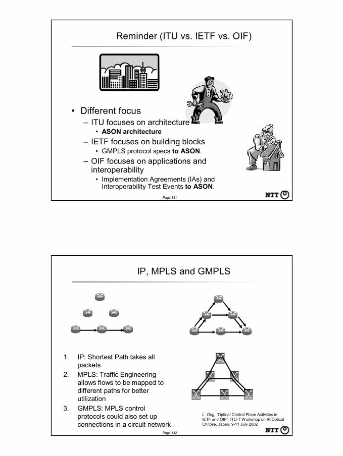
• Different focus– ITU focuses on architecture
• ASON architecture– IETF focuses on building blocks
• GMPLS protocol specs to ASON.– OIF focuses on applications and
interoperability• Implementation Agreements (IAs) and
Interoperability Test Events to ASON.
Reminder (ITU vs. IETF vs. OIF)
Page 132
IP, MPLS and GMPLS
1. IP: Shortest Path takes all packets
2. MPLS: Traffic Engineering allows flows to be mapped to different paths for better utilization
3. GMPLS: MPLS control protocols could also set up connections in a circuit network
L. Ong, “Optical Control Plane Activities in IETF and OIF”, ITU-T Workshop on IP/Optical Chitose, Japan, 9-11 July 2002

Page 133
MPLambdaS (MPλS) and GMPLS
• Multi-Protocol Lambda Switching: October 1999– Combining MPLS Traffic Engineering Control With Optical
Crossconnects (OXCs)1. provide a framework for real-time provisioning of optical channels in
automatically switched optical networks2. foster the expedited development and deployment of a new class of
versatile OXCs3. allow the use of uniform semantics for network management and
operations control in hybrid networks consisting of OXCs and labelswitching routers (LSRs).
– The proposed approach is particularly advantageous for OXCsintended for data-centric optical internetworking systems.
• This concept can be extent to other circuit switch systems.– Attempt to SDH control: March 2000– Generalized Multi-protocol Label Switching (GMPLS): June 2000
Page 134
GMPLS controllable equipments
• Packet-Switch Capable (PSC) : MPLS Router• Time-Division Multiplex Capable (TDM) : SDH (VC)-
XC• Lambda-Switch Capable (LSC) : OXC, PXC
– Include both single wavelength switch and multi-wavelength (waveband) switch
• Fiber-Switch Capable (FSC) : PXC
• Layer2-Switch Capable (L2SC) : ATM-SW, FR-SW, etc. [GbE-SW (?)]– Defined. But not implemented.

Page 135
GMPLS LSP Hierarchy
LSP(Fiber Switch Basis)
LSP(Wavelength Switch Basis)
LSP(TDM Switch Basis)
LSP(Cell/Packet Switch Basis)
Fiber
Wavelength (Group)
Time slot
Cell/Packet
Page 136
GMPLS protocols
GMPLS signaling Protocol:Extensions to MPLS signaling required
to support five switching classes (PSC, TDM, LSC, FSC, and L2SC) in GMPLS.
GMPLS CR-LDP extensionsGMPLS RSVP-TE extensions
Link Management Protocol (LMP):runs between neighboring nodes is used to manage traffic engineering
(TE) links.will be used to maintain control
channel connectivity, verify the physical connectivity, correlate the link property information, and manage link failures.
IP based Control Plane
GMPLS routing protocol:D-Plane topology discoveryPath route selectionSwitching capability advertisement
OSPF-TE GMPLS extensions
Focused in this tutorial

Page 137
Hierarchical LSP and Signaling (1/2)
Ayan Banerjee, et al., “Generalized Multiprotocol Label Switching: An Overview of Signaling Enhancements andRecovery Techniques”IEEE Communication Magazine, Vol. 39, No. 7, July 2001.
Packet (PSC) LSP1
λ (LSC) LSP3
Fiber (FSC) LSP4
Time slot (TDM) LSP2
LSC
FSC
Page 138
Hierarchical LSP and Signaling (2/2)
Ayan Banerjee, et al., “Generalized Multiprotocol Label Switching: An Overview of Signaling Enhancements andRecovery Techniques”IEEE Communication Magazine, Vol. 39, No. 7, July 2001.
PSC LSP
TDM LSP
LSC LSP
FSC LSP
GMPLS RSVP-TE signaling

Page 139
OIF OUNI and IETF GMPLS Inter-working
OUNI Resv
ResvConf
ResvConf+ MESSAGE_ID_ACK
ACK
UNI Transport Connection EstablishedSource UNI-C may start transmitting
Destination UNI-C may start transmitting
ACK
R1 XC2XC1
OUNI Path
ACK S=R1, D=R2
S=R1, D=R2
I-NNI Path
OUNI Resv+ MESSAGE_ID_ACK
OUNI Path
ACK
S=R1, D=R2
I-NNI ResvMESSAGE_ID
MESSAGE_IDI-NNI ResvConf
R2OUNI OUNIGMPLS
Page 140
UNI - E-NNI Inter-working
Path
Path
Rev
Resv+ MESSAGE_ID_ACK
ACK
NNI Transport Connection EstablishedSource NNI may start transmitting
ACK
Source UNI-C Destination UNI-CUNI-N I-NNI
ResvConf
ResvConf+ MESSAGE_ID_ACK
ACK
Destination NNI may start transmitting
PathACK
ACKResv
ACKResvConf
I-NNI E-NNI E-NNI I-NNI I-NNI UNI-N
Vendor Vendor AA Vendor Vendor BB

Page 141
GMPLS Management (MIBs)
• Link Management Protocol Management Information Base– draft-ietf-ccamp-lmp-mib-06.txt
• lmpNbrTable, lmpControlChannelTable, lmpControlChannelPerfTable, lmpTeLinkTable, lmpLinkVerificationTable, lmpTeLinkPerfTable, lmpDataLinkTable, lmpDataLinkPerfTable
• Generalized Multiprotocol Label Switching (GMPLS) Label Switch Router Management Information Base– draft-ietf-ccamp-gmpls-lsr-mib-00.txt
• gmplsInterfaceConfTable, gmplsInSegmentTable, gmplsOutSegmentTable, gmplsLabelTable
• Generalized Multiprotocol Label Switching (GMPLS) Traffic Engineering Management Information Base– draft-ietf-ccamp-gmpls-te-mib-00.txt
• gmplsTunnelTable, gmplsTunnelHopTable, gmplsTunnelARHopTable, gmplsTunnelCHopTable, gmplsTunnelPerfTable, gmplsTunnelErrorTable
Page 142
Outline
• Photonic Network Control and Management Overview
• Photonic Network Architecture Overview• IP over Photonic Network Architecture Overview• MPLS, GMPLS (MPLambdaS), and ASON• GMPLS protocols• GMPLS management• Interoperability Test Events of Photonic Network
Control– OIF (OUNI, E-NNI)– MPLS Forum (GMPLS signaling)

Page 143
SuperComm2001 OIF UNI demo
• 25 vendors– 14 client equipment (e.g. IP router)– 14 optical equipment (e.g. OXC)
• Some vendors are software only testing.
Vendor XVendor X Vendor YVendor Y
Vendor ZVendor Z
CC--Plane NetworkPlane Network
Page 144
Interoperability Results
A B C D E*2 F G H I J K L*2 M N1 H H *1
2 H H3 *1 *1 *1
4 H H *1
56 *1
7 H H H8 *1
9 *1 *1 *1
10*2 H H11 *1
12 H H H H H H *1 H H *1 H13 H14 H *1
*1 - Not enough time to complete testing*2 - Proxy or test device supports control plane only.H = Another client was used to form Hetrogeneous testResults scrambled to protect individual companiesTested, Signaling & Transport success
ONE Device
Clie
nt D
evic
e
Color KeyNot Interoperable
Tested, Signaling success
•Over 196 Tests Conducted
99.5% Signaling Inter-working
68.6% Signaling & Transport Inter-working

Page 145
OFC2003 UNI/E-NNI demo
• 12 vendors, 15 systems.• UNI GMPLS E-NNI GMPLS UNI
Page 146
GMPLS Interoperability demonstration
• Held at UNH Interoperability Lab• Staging for GMPLS demo at NGN 2002• Organized by The MPLS Forum• Participants
– Equipment ImplementationsRouters: Cisco, JuniperSwitch: Sycamore
– Emulated ImplementationsStacks: Netplane, DCLTest Eqpt: Agilent, NetTest

Page 147
Overview of GMPLS Interop
Page 148
Thank you !


![Design of Service Abstraction Model for Enhancing …altair.chonnam.ac.kr/~kbkim/papers/[2016 APNOMS]Design of...Software Defined Network (SDN) and Network Function Virtualization](https://img.pdfslide.net/doc/110x75/5f0aefe67e708231d42e12dc/design-of-service-abstraction-model-for-enhancing-kbkimpapers2016-apnomsdesign.jpg)