Embed Size (px)
Citation preview
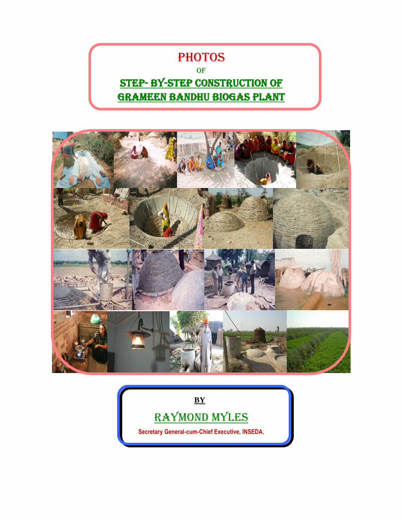
PHOTOS OF
STEP- BY-STEP CONSTRUCTION OF GRAMEEN BANDHU BIOGAS PLANT
BY
RAYMOND MYLES Secretary General-cum-Chief Executive, INSEDA,
PHOTOS OF STEP-BY-STEP WEAVING AND CONSTRUCTION Of GRAMEEN BANDHU BIOGAS PLANT
GRAMEEN BANDHU PHOTOS: : Raymond Myles, Secretary General-cum-Chief Executive, INSEDA, New Delhi
2
PICTORIAL DEPICTION OF IMPORTANT STAGES OF BUILDING OF GRAMEEN BANDHU BIOGAS PLANT (GBP)
I. Fabrication and pre-fabrication of bamboo structures {(weaving using 0.5 in (12.5 mm or
1.25 cm)} bamboo strips for Grameen Bandhu model biogas plant (photograph nos. 1 to 16)
1 (a) 1 (b) 1 (c)
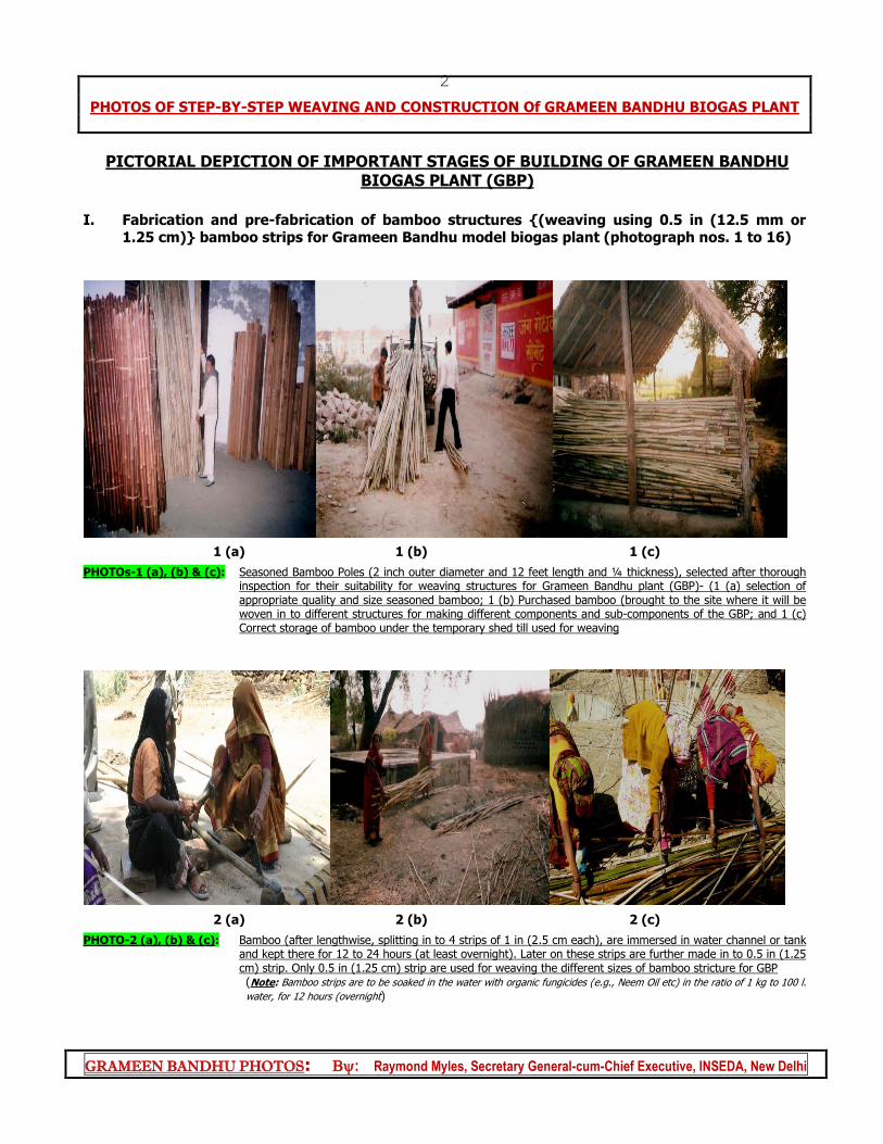
PHOTOs-1 (a), (b) & (c): Seasoned Bamboo Poles (2 inch outer diameter and 12 feet length and ¼ thickness), selected after thorough inspection for their suitability for weaving structures for Grameen Bandhu plant (GBP)- (1 (a) selection of appropriate quality and size seasoned bamboo; 1 (b) Purchased bamboo (brought to the site where it will be woven in to different structures for making different components and sub-components of the GBP; and 1 (c) Correct storage of bamboo under the temporary shed till used for weaving
2 (a) 2 (b) 2 (c)
PHOTO-2 (a), (b) & (c): Bamboo (after lengthwise, splitting in to 4 strips of 1 in (2.5 cm each), are immersed in water channel or tank and kept there for 12 to 24 hours (at least overnight). Later on these strips are further made in to 0.5 in (1.25 cm) strip. Only 0.5 in (1.25 cm) strip are used for weaving the different sizes of bamboo stricture for GBP (Note: Bamboo strips are to be soaked in the water with organic fungicides (e.g., Neem Oil etc) in the ratio of 1 kg to 100 l.
water, for 12 hours (overnight)
PHOTOS OF STEP-BY-STEP WEAVING AND CONSTRUCTION Of GRAMEEN BANDHU BIOGAS PLANT
GRAMEEN BANDHU PHOTOS: : Raymond Myles, Secretary General-cum-Chief Executive, INSEDA, New Delhi
3
3 (a) 3 (b)
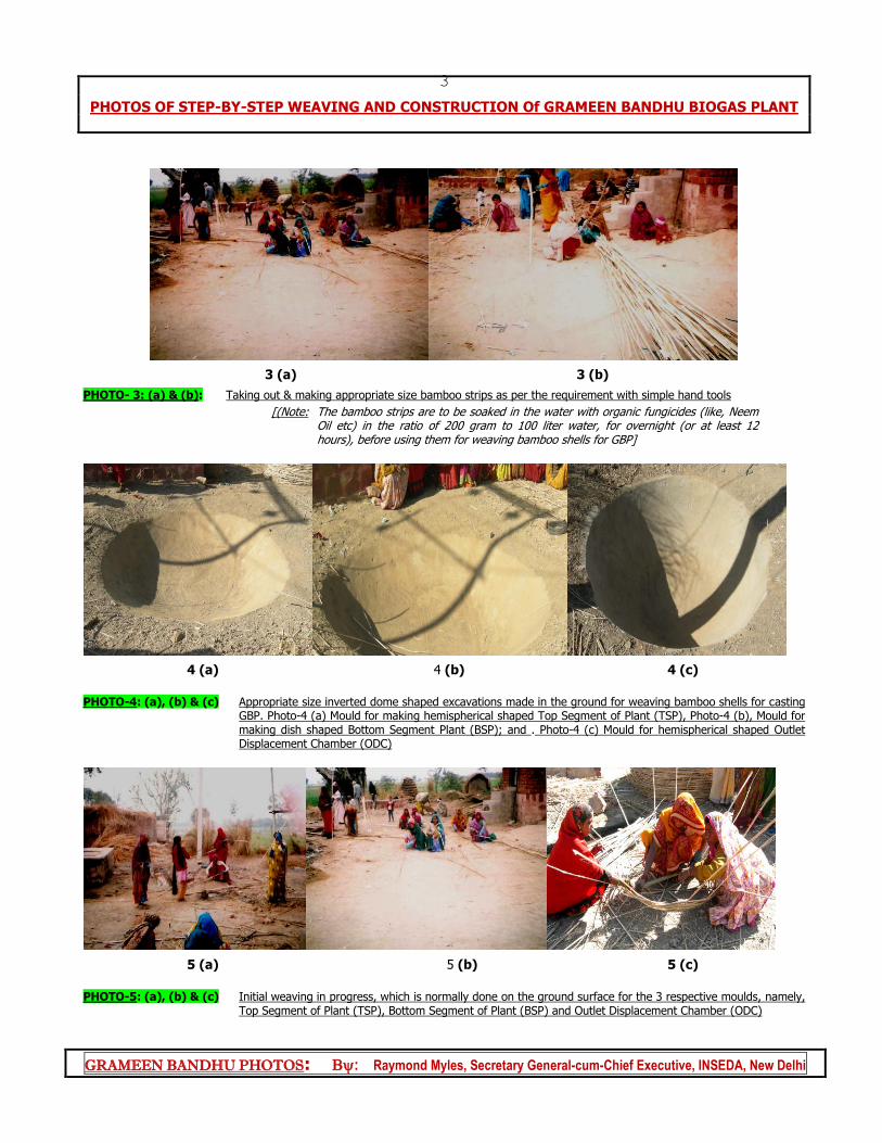
PHOTO- 3: (a) & (b): Taking out & making appropriate size bamboo strips as per the requirement with simple hand tools
[(Note: The bamboo strips are to be soaked in the water with organic fungicides (like, Neem Oil etc) in the ratio of 200 gram to 100 liter water, for overnight (or at least 12 hours), before using them for weaving bamboo shells for GBP]
4 (a) 4 (b) 4 (c)
PHOTO-4: (a), (b) & (c) Appropriate size inverted dome shaped excavations made in the ground for weaving bamboo shells for casting
GBP. Photo-4 (a) Mould for making hemispherical shaped Top Segment of Plant (TSP), Photo-4 (b), Mould for making dish shaped Bottom Segment Plant (BSP); and . Photo-4 (c) Mould for hemispherical shaped Outlet Displacement Chamber (ODC)
5 (a) 5 (b) 5 (c)
PHOTO-5: (a), (b) & (c) Initial weaving in progress, which is normally done on the ground surface for the 3 respective moulds, namely,
Top Segment of Plant (TSP), Bottom Segment of Plant (BSP) and Outlet Displacement Chamber (ODC)
PHOTOS OF STEP-BY-STEP WEAVING AND CONSTRUCTION Of GRAMEEN BANDHU BIOGAS PLANT
GRAMEEN BANDHU PHOTOS: : Raymond Myles, Secretary General-cum-Chief Executive, INSEDA, New Delhi
4
6 (a) 6 (b) 6 (c)
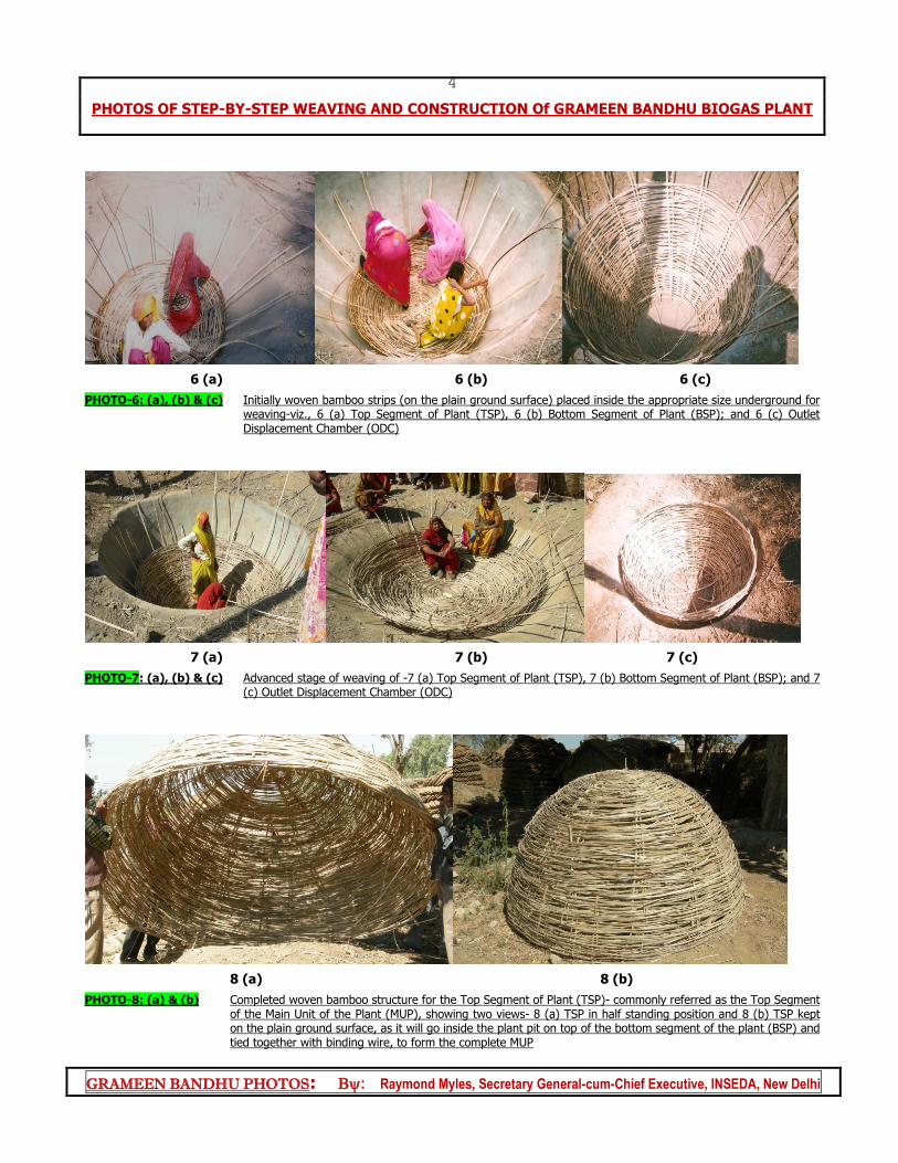
PHOTO-6: (a), (b) & (c) Initially woven bamboo strips (on the plain ground surface) placed inside the appropriate size underground for weaving-viz., 6 (a) Top Segment of Plant (TSP), 6 (b) Bottom Segment of Plant (BSP); and 6 (c) Outlet Displacement Chamber (ODC)
7 (a) 7 (b) 7 (c)
PHOTO-7: (a), (b) & (c) Advanced stage of weaving of -7 (a) Top Segment of Plant (TSP), 7 (b) Bottom Segment of Plant (BSP); and 7 (c) Outlet Displacement Chamber (ODC)
8 (a) 8 (b)
PHOTO-8: (a) & (b) Completed woven bamboo structure for the Top Segment of Plant (TSP)- commonly referred as the Top Segment of the Main Unit of the Plant (MUP), showing two views- 8 (a) TSP in half standing position and 8 (b) TSP kept on the plain ground surface, as it will go inside the plant pit on top of the bottom segment of the plant (BSP) and tied together with binding wire, to form the complete MUP

PHOTOS OF STEP-BY-STEP WEAVING AND CONSTRUCTION Of GRAMEEN BANDHU BIOGAS PLANT
GRAMEEN BANDHU PHOTOS: : Raymond Myles, Secretary General-cum-Chief Executive, INSEDA, New Delhi
5
9 (a) 9 (b)
PHOTO-9: (a) & (b) Completed woven bamboo structure for the Bottom Segment of Plant (BSP)- commonly referred as the Bottom Segment of the Main Unit of the Plant (MUP), showing two views- 9 (a) BSP in tilted position supported by trained rural women weavers and 9 (b) BSP kept in inverted position on the plain ground surface, as it will go inside the plant pit on the surface of the foundation. Later on the top segment of the plant (TSP) would be place on it and both will be tied together with binding wire, to form the complete MUP
10 (a) 10 (b)
PHOTO-10: (a), (b) & (c)_ Completed woven bamboo structure for the Outlet Displacement Chamber (ODC)- Showing two views- Photo 10 (a) ODC (weaving is just completed with opening for manhole on its crown inside the UGM) ready to be taken out; Photo-10 (b) ODC kept on ground, with the two structure for TSP & BSP ready inside their respective underground moulds, can be seen at the back (UGMs); and Photo-10 (c) ODC kept on the ground surface in inverted position (with opening for manhole on its crown) as it will go on the ODC foundation.
11 (a) 11 (b)
PHOTO-11: (a) & (b) Completed woven bamboo structures for- Photo-11 (a) Top Segment (TSP) and Bottom Segment (BSP) of the Main Unit of Plant (MSU), Photo-11 (b) TSP is placed on top of BSP as they would be placed inside the plant pit before joining them together tightly using binding wire, before plastering them using cement sand mortar
PHOTOS OF STEP-BY-STEP WEAVING AND CONSTRUCTION Of GRAMEEN BANDHU BIOGAS PLANT
GRAMEEN BANDHU PHOTOS: : Raymond Myles, Secretary General-cum-Chief Executive, INSEDA, New Delhi
6
12 (a) 12 (b)
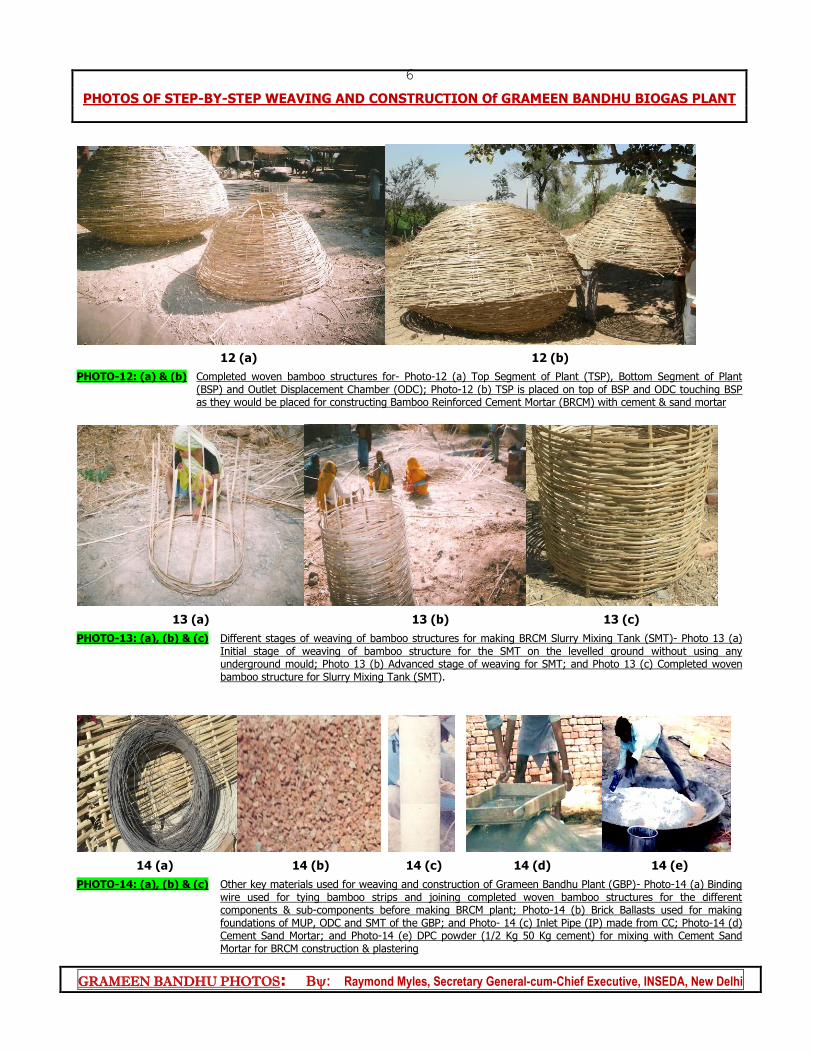
PHOTO-12: (a) & (b) Completed woven bamboo structures for- Photo-12 (a) Top Segment of Plant (TSP), Bottom Segment of Plant (BSP) and Outlet Displacement Chamber (ODC); Photo-12 (b) TSP is placed on top of BSP and ODC touching BSP as they would be placed for constructing Bamboo Reinforced Cement Mortar (BRCM) with cement & sand mortar
13 (a) 13 (b) 13 (c)
PHOTO-13: (a), (b) & (c) Different stages of weaving of bamboo structures for making BRCM Slurry Mixing Tank (SMT)- Photo 13 (a) Initial stage of weaving of bamboo structure for the SMT on the levelled ground without using any underground mould; Photo 13 (b) Advanced stage of weaving for SMT; and Photo 13 (c) Completed woven bamboo structure for Slurry Mixing Tank (SMT).
14 (a) 14 (b) 14 (c) 14 (d) 14 (e)
PHOTO-14: (a), (b) & (c) Other key materials used for weaving and construction of Grameen Bandhu Plant (GBP)- Photo-14 (a) Binding wire used for tying bamboo strips and joining completed woven bamboo structures for the different components & sub-components before making BRCM plant; Photo-14 (b) Brick Ballasts used for making foundations of MUP, ODC and SMT of the GBP; and Photo- 14 (c) Inlet Pipe (IP) made from CC; Photo-14 (d) Cement Sand Mortar; and Photo-14 (e) DPC powder (1/2 Kg 50 Kg cement) for mixing with Cement Sand Mortar for BRCM construction & plastering
PHOTOS OF STEP-BY-STEP WEAVING AND CONSTRUCTION Of GRAMEEN BANDHU BIOGAS PLANT
GRAMEEN BANDHU PHOTOS: : Raymond Myles, Secretary General-cum-Chief Executive, INSEDA, New Delhi
7
15 (a) 15 (b) 15 (c)
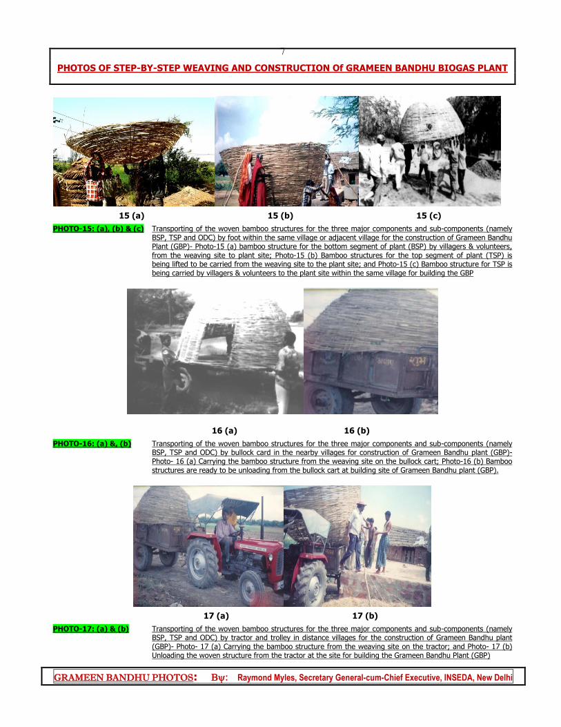
PHOTO-15: (a), (b) & (c) Transporting of the woven bamboo structures for the three major components and sub-components (namely BSP, TSP and ODC) by foot within the same village or adjacent village for the construction of Grameen Bandhu Plant (GBP)- Photo-15 (a) bamboo structure for the bottom segment of plant (BSP) by villagers & volunteers, from the weaving site to plant site; Photo-15 (b) Bamboo structures for the top segment of plant (TSP) is being lifted to be carried from the weaving site to the plant site; and Photo-15 (c) Bamboo structure for TSP is being carried by villagers & volunteers to the plant site within the same village for building the GBP
16 (a) 16 (b)
PHOTO-16: (a) &, (b) Transporting of the woven bamboo structures for the three major components and sub-components (namely BSP, TSP and ODC) by bullock card in the nearby villages for construction of Grameen Bandhu plant (GBP)- Photo- 16 (a) Carrying the bamboo structure from the weaving site on the bullock cart; Photo-16 (b) Bamboo structures are ready to be unloading from the bullock cart at building site of Grameen Bandhu plant (GBP).
17 (a) 17 (b)
PHOTO-17: (a) & (b) Transporting of the woven bamboo structures for the three major components and sub-components (namely BSP, TSP and ODC) by tractor and trolley in distance villages for the construction of Grameen Bandhu plant (GBP)- Photo- 17 (a) Carrying the bamboo structure from the weaving site on the tractor; and Photo- 17 (b) Unloading the woven structure from the tractor at the site for building the Grameen Bandhu Plant (GBP)
PHOTOS OF STEP-BY-STEP WEAVING AND CONSTRUCTION Of GRAMEEN BANDHU BIOGAS PLANT
GRAMEEN BANDHU PHOTOS: : Raymond Myles, Secretary General-cum-Chief Executive, INSEDA, New Delhi
8
II. BUILDING OF GRAMEEN BANDHU PLANT (GBP) AT FARMER'S SITE
a). Digging pit, laying of foundation and the fixing of bamboo Shell structures for the
MUP- (Photograph No. 18 to 21)
18 (a) 18 (b) 18 (c)
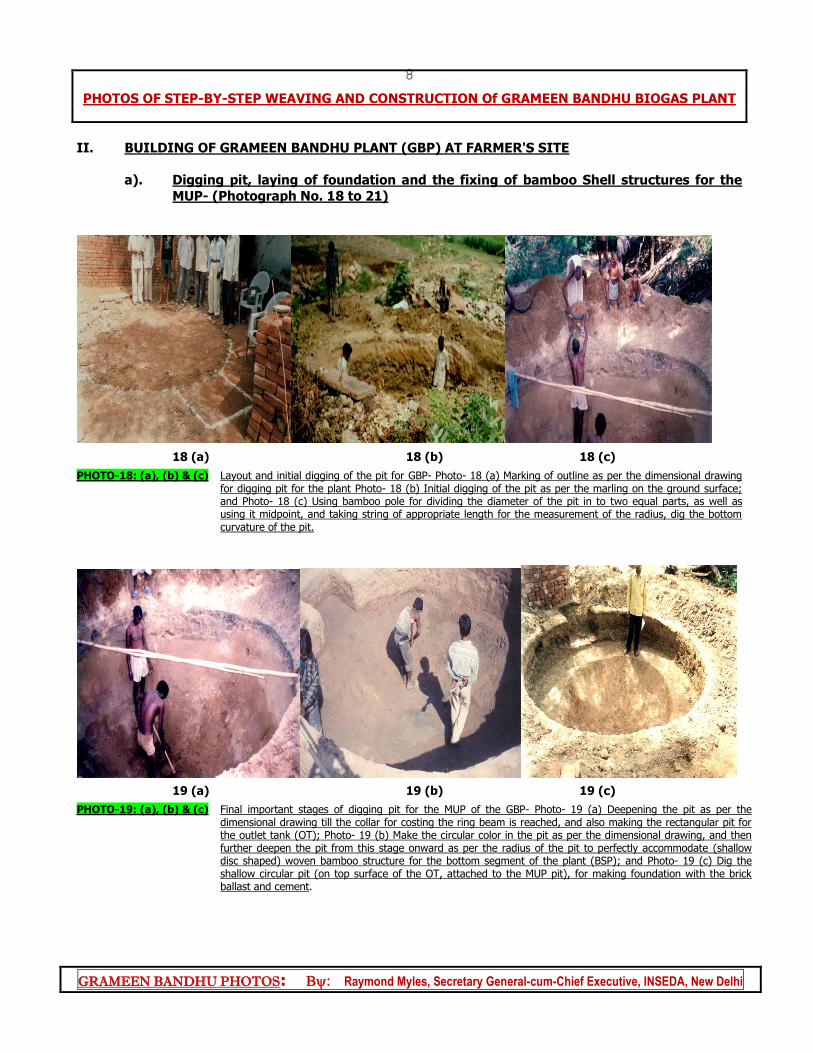
PHOTO-18: (a), (b) & (c) Layout and initial digging of the pit for GBP- Photo- 18 (a) Marking of outline as per the dimensional drawing for digging pit for the plant Photo- 18 (b) Initial digging of the pit as per the marling on the ground surface; and Photo- 18 (c) Using bamboo pole for dividing the diameter of the pit in to two equal parts, as well as using it midpoint, and taking string of appropriate length for the measurement of the radius, dig the bottom curvature of the pit.
19 (a) 19 (b) 19 (c)
PHOTO-19: (a), (b) & (c) Final important stages of digging pit for the MUP of the GBP- Photo- 19 (a) Deepening the pit as per the dimensional drawing till the collar for costing the ring beam is reached, and also making the rectangular pit for the outlet tank (OT); Photo- 19 (b) Make the circular color in the pit as per the dimensional drawing, and then further deepen the pit from this stage onward as per the radius of the pit to perfectly accommodate (shallow disc shaped) woven bamboo structure for the bottom segment of the plant (BSP); and Photo- 19 (c) Dig the shallow circular pit (on top surface of the OT, attached to the MUP pit), for making foundation with the brick ballast and cement.
PHOTOS OF STEP-BY-STEP WEAVING AND CONSTRUCTION Of GRAMEEN BANDHU BIOGAS PLANT
GRAMEEN BANDHU PHOTOS: : Raymond Myles, Secretary General-cum-Chief Executive, INSEDA, New Delhi
9
20 (a) 20 (b) 20 (c)
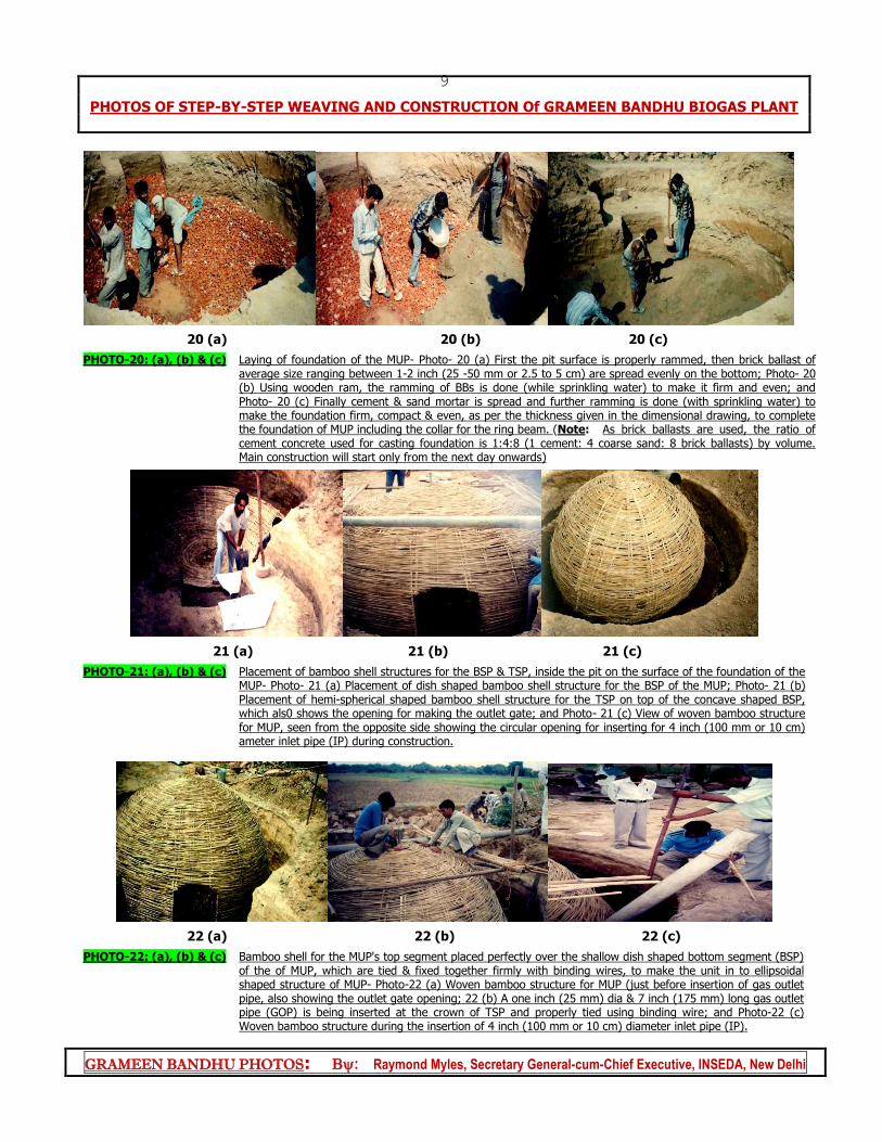
PHOTO-20: (a), (b) & (c) Laying of foundation of the MUP- Photo- 20 (a) First the pit surface is properly rammed, then brick ballast of average size ranging between 1-2 inch (25 -50 mm or 2.5 to 5 cm) are spread evenly on the bottom; Photo- 20 (b) Using wooden ram, the ramming of BBs is done (while sprinkling water) to make it firm and even; and Photo- 20 (c) Finally cement & sand mortar is spread and further ramming is done (with sprinkling water) to make the foundation firm, compact & even, as per the thickness given in the dimensional drawing, to complete the foundation of MUP including the collar for the ring beam. (Note: As brick ballasts are used, the ratio of cement concrete used for casting foundation is 1:4:8 (1 cement: 4 coarse sand: 8 brick ballasts) by volume. Main construction will start only from the next day onwards)
21 (a) 21 (b) 21 (c)
PHOTO-21: (a), (b) & (c) Placement of bamboo shell structures for the BSP & TSP, inside the pit on the surface of the foundation of the MUP- Photo- 21 (a) Placement of dish shaped bamboo shell structure for the BSP of the MUP; Photo- 21 (b) Placement of hemi-spherical shaped bamboo shell structure for the TSP on top of the concave shaped BSP, which als0 shows the opening for making the outlet gate; and Photo- 21 (c) View of woven bamboo structure for MUP, seen from the opposite side showing the circular opening for inserting for 4 inch (100 mm or 10 cm) ameter inlet pipe (IP) during construction.
22 (a) 22 (b) 22 (c)
PHOTO-22: (a), (b) & (c) Bamboo shell for the MUP's top segment placed perfectly over the shallow dish shaped bottom segment (BSP) of the of MUP, which are tied & fixed together firmly with binding wires, to make the unit in to ellipsoidal shaped structure of MUP- Photo-22 (a) Woven bamboo structure for MUP (just before insertion of gas outlet pipe, also showing the outlet gate opening; 22 (b) A one inch (25 mm) dia & 7 inch (175 mm) long gas outlet pipe (GOP) is being inserted at the crown of TSP and properly tied using binding wire; and Photo-22 (c) Woven bamboo structure during the insertion of 4 inch (100 mm or 10 cm) diameter inlet pipe (IP).
PHOTOS OF STEP-BY-STEP WEAVING AND CONSTRUCTION Of GRAMEEN BANDHU BIOGAS PLANT
GRAMEEN BANDHU PHOTOS: : Raymond Myles, Secretary General-cum-Chief Executive, INSEDA, New Delhi
10
b). Main construction work on the Grameen Bandhu plant-GBP (Photograph No 23- 32)
23 (a) 23 (b)
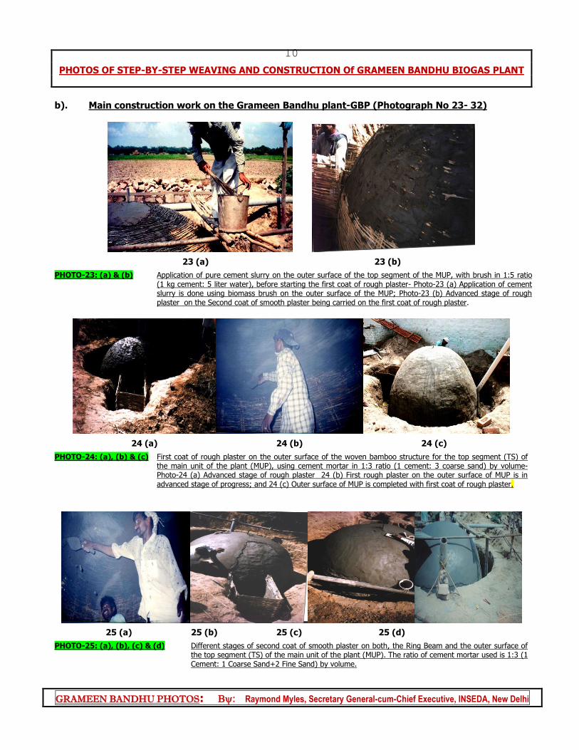
PHOTO-23: (a) & (b) Application of pure cement slurry on the outer surface of the top segment of the MUP, with brush in 1:5 ratio (1 kg cement: 5 liter water), before starting the first coat of rough plaster- Photo-23 (a) Application of cement slurry is done using biomass brush on the outer surface of the MUP; Photo-23 (b) Advanced stage of rough plaster on the Second coat of smooth plaster being carried on the first coat of rough plaster.
24 (a) 24 (b) 24 (c)
PHOTO-24: (a), (b) & (c) First coat of rough plaster on the outer surface of the woven bamboo structure for the top segment (TS) of the main unit of the plant (MUP), using cement mortar in 1:3 ratio (1 cement: 3 coarse sand) by volume- Photo-24 (a) Advanced stage of rough plaster 24 (b) First rough plaster on the outer surface of MUP is in advanced stage of progress; and 24 (c) Outer surface of MUP is completed with first coat of rough plaster.
25 (a) 25 (b) 25 (c) 25 (d)
PHOTO-25: (a), (b), (c) & (d) Different stages of second coat of smooth plaster on both, the Ring Beam and the outer surface of the top segment (TS) of the main unit of the plant (MUP). The ratio of cement mortar used is 1:3 (1 Cement: 1 Coarse Sand+2 Fine Sand) by volume.
PHOTOS OF STEP-BY-STEP WEAVING AND CONSTRUCTION Of GRAMEEN BANDHU BIOGAS PLANT
GRAMEEN BANDHU PHOTOS: : Raymond Myles, Secretary General-cum-Chief Executive, INSEDA, New Delhi
11
26 (a) 26 (b) 26 (c)
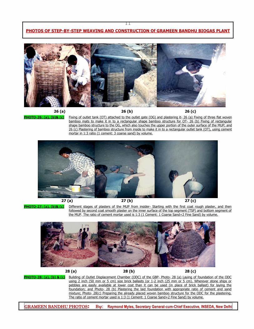
PHOTO-26: (a), (b)& (c) Fixing of outlet tank (OT) attached to the outlet gate (OG) and plastering it- 26 (a) Fixing of three flat woven bamboo mats to make it in to a rectangular shape bamboo structure for OT- 26 (b) Fixing of rectangular shape bamboo structure to the OG, which also touches the upper portion of the outer surface of the MUP; and 26 (c) Plastering of bamboo structure from inside to make it in to a rectangular outlet tank (OT), using cement mortar in 1:3 ratio (1 cement: 3 coarse sand) by volume.
27 (a) 27 (b) 27 (c)
PHOTO-27: (a), (b)& (c) Different stages of plasters of the MUP from insider- Starting with the first coat rough plaster, and then followed by second coat smooth plaster on the inner surface of the top segment (TSP) and bottom segment of the MUP. The ratio of cement mortar used is 1:3 (1 Cement: 1 Coarse Sand+2 Fine Sand) by volume.
28 (a) 28 (b) 28 (c)
PHOTO-28: (a), (b) & (c) Building of Outlet Displacement Chamber (ODC) of the GBP- Photo- 28 (a) Laying of foundation of the ODC using 2 inch (50 mm or 5 cm) size brick ballasts (or 1-2 inch (25 mm or 5 cm). Wherever stone ships or pebbles are easily available at lower cost than it can be used (in place of brick ballast) for laying the foundation; and Photo- 28 (b) Plastering the laid foundation with appropriate ratio of cement and sand mixture; Photo- 28(c) Preparing the already placed woven bamboo structure for the ODC for the plastering. The ratio of cement mortar used is 1:3 (1 Cement: 1 Coarse Sand+2 Fine Sand) by volume.
PHOTOS OF STEP-BY-STEP WEAVING AND CONSTRUCTION Of GRAMEEN BANDHU BIOGAS PLANT
GRAMEEN BANDHU PHOTOS: : Raymond Myles, Secretary General-cum-Chief Executive, INSEDA, New Delhi
12
29 (a) 29 (b) 29 (c)
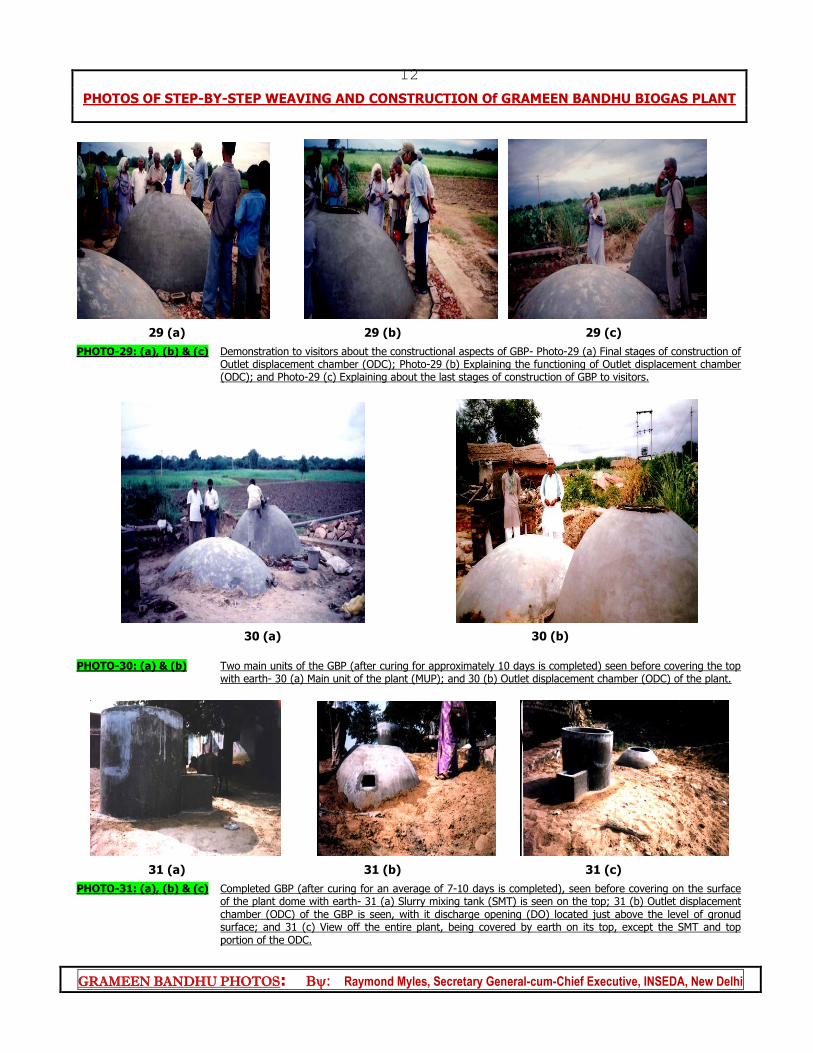
PHOTO-29: (a), (b) & (c) Demonstration to visitors about the constructional aspects of GBP- Photo-29 (a) Final stages of construction of Outlet displacement chamber (ODC); Photo-29 (b) Explaining the functioning of Outlet displacement chamber (ODC); and Photo-29 (c) Explaining about the last stages of construction of GBP to visitors.
30 (a) 30 (b)
PHOTO-30: (a) & (b) Two main units of the GBP (after curing for approximately 10 days is completed) seen before covering the top
with earth- 30 (a) Main unit of the plant (MUP); and 30 (b) Outlet displacement chamber (ODC) of the plant.
31 (a) 31 (b) 31 (c)
PHOTO-31: (a), (b) & (c) Completed GBP (after curing for an average of 7-10 days is completed), seen before covering on the surface of the plant dome with earth- 31 (a) Slurry mixing tank (SMT) is seen on the top; 31 (b) Outlet displacement chamber (ODC) of the GBP is seen, with it discharge opening (DO) located just above the level of gronud surface; and 31 (c) View off the entire plant, being covered by earth on its top, except the SMT and top portion of the ODC.
PHOTOS OF STEP-BY-STEP WEAVING AND CONSTRUCTION Of GRAMEEN BANDHU BIOGAS PLANT
GRAMEEN BANDHU PHOTOS: : Raymond Myles, Secretary General-cum-Chief Executive, INSEDA, New Delhi
13
32 (a) 32 (b)
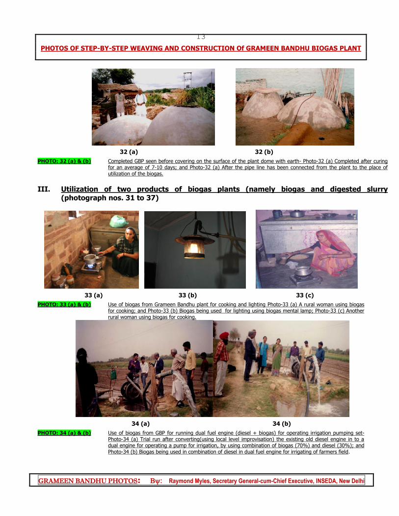
PHOTO: 32 (a) & (b) Completed GBP seen before covering on the surface of the plant dome with earth- Photo-32 (a) Completed after curing for an average of 7-10 days; and Photo-32 (a) After the pipe line has been connected from the plant to the place of utilization of the biogas.
III. Utilization of two products of biogas plants (namely biogas and digested slurry (photograph nos. 31 to 37)
33 (a) 33 (b) 33 (c)
PHOTO: 33 (a) & (b) Use of biogas from Grameen Bandhu plant for cooking and lighting Photo-33 (a) A rural woman using biogas for cooking; and Photo-33 (b) Biogas being used for lighting using biogas mental lamp; Photo-33 (c) Another rural woman using biogas for cooking.
34 (a) 34 (b)
PHOTO: 34 (a) & (b) Use of biogas from GBP for running dual fuel engine (diesel + biogas) for operating irrigation pumping set- Photo-34 (a) Trial run after converting(using local level improvisation) the existing old diesel engine in to a dual engine for operating a pump for irrigation, by using combination of biogas (70%) and diesel (30%); and Photo-34 (b) Biogas being used in combination of diesel in dual fuel engine for irrigating of farmers field.
PHOTOS OF STEP-BY-STEP WEAVING AND CONSTRUCTION Of GRAMEEN BANDHU BIOGAS PLANT
GRAMEEN BANDHU PHOTOS: : Raymond Myles, Secretary General-cum-Chief Executive, INSEDA, New Delhi
14
35 (a) 35 (b)
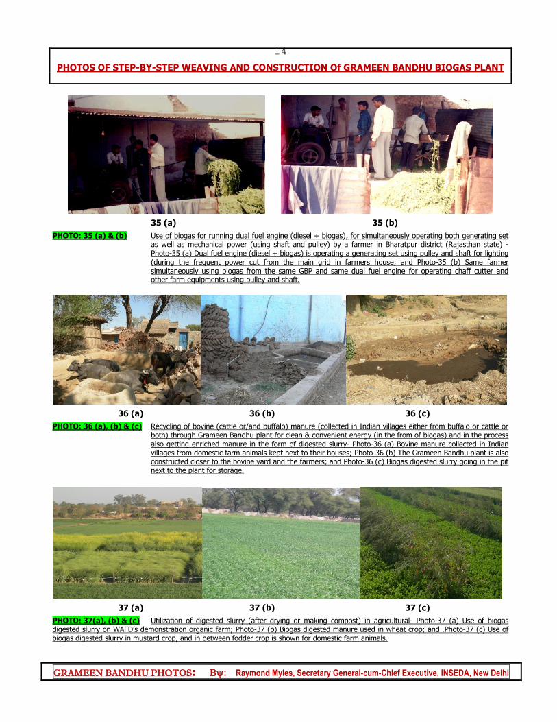
PHOTO: 35 (a) & (b) Use of biogas for running dual fuel engine (diesel + biogas), for simultaneously operating both generating set as well as mechanical power (using shaft and pulley) by a farmer in Bharatpur district (Rajasthan state) - Photo-35 (a) Dual fuel engine (diesel + biogas) is operating a generating set using pulley and shaft for lighting (during the frequent power cut from the main grid in farmers house; and Photo-35 (b) Same farmer simultaneously using biogas from the same GBP and same dual fuel engine for operating chaff cutter and other farm equipments using pulley and shaft.
36 (a) 36 (b) 36 (c)
PHOTO: 36 (a), (b) & (c) Recycling of bovine (cattle or/and buffalo) manure (collected in Indian villages either from buffalo or cattle or both) through Grameen Bandhu plant for clean & convenient energy (in the from of biogas) and in the process also getting enriched manure in the form of digested slurry- Photo-36 (a) Bovine manure collected in Indian villages from domestic farm animals kept next to their houses; Photo-36 (b) The Grameen Bandhu plant is also constructed closer to the bovine yard and the farmers; and Photo-36 (c) Biogas digested slurry going in the pit next to the plant for storage.
37 (a) 37 (b) 37 (c)
PHOTO: 37(a), (b) & (c) Utilization of digested slurry (after drying or making compost) in agricultural- Photo-37 (a) Use of biogas digested slurry on WAFD’s demonstration organic farm; Photo-37 (b) Biogas digested manure used in wheat crop; and .Photo-37 (c) Use of biogas digested slurry in mustard crop, and in between fodder crop is shown for domestic farm animals.