Embed Size (px)
Citation preview
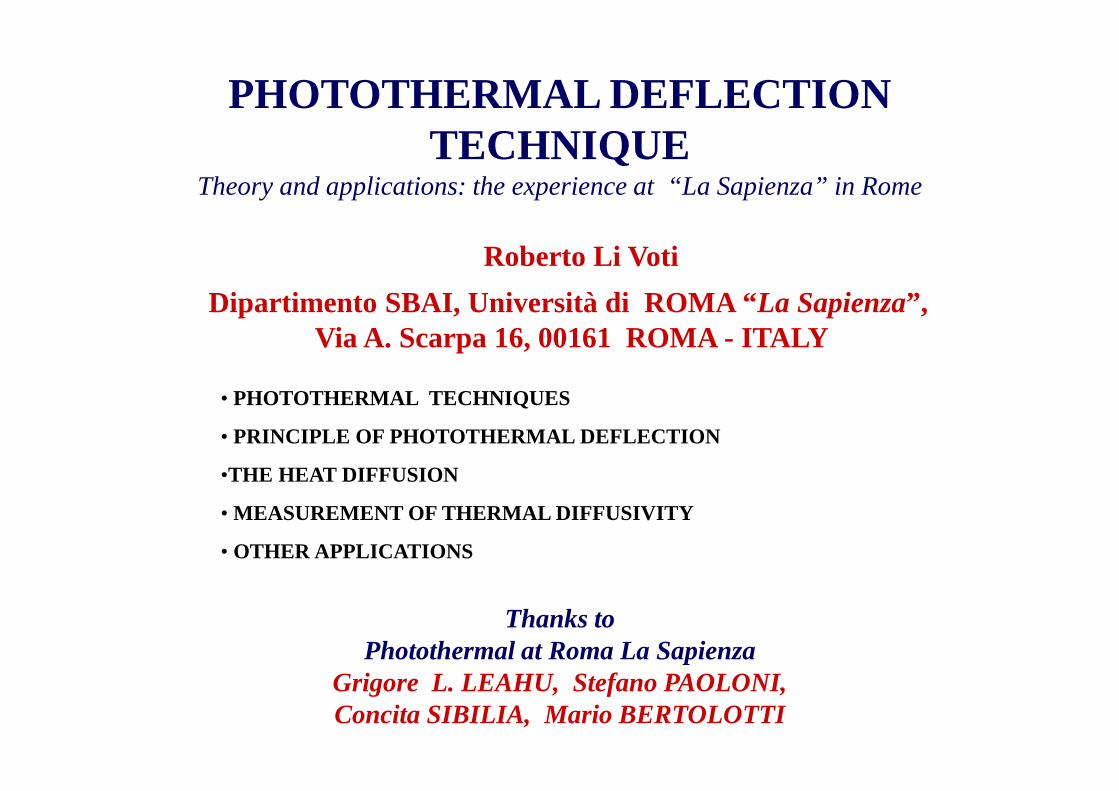
Dipartimento SBAI, Università di ROMA “ La Sapienza”, Via A. Scarpa 16, 00161 ROMA - ITALY
PHOTOTHERMAL DEFLECTION TECHNIQUE
Theory and applications: the experience at “La Sapienza” in Rome
Roberto Li Voti
• PHOTOTHERMAL TECHNIQUES
• PRINCIPLE OF PHOTOTHERMAL DEFLECTION
•THE HEAT DIFFUSION
• MEASUREMENT OF THERMAL DIFFUSIVITY
• OTHER APPLICATIONS
Thanks to Photothermal at Roma La Sapienza
Grigore L. LEAHU, Stefano PAOLONI, Concita SIBILIA, Mario BERTOLOTTI
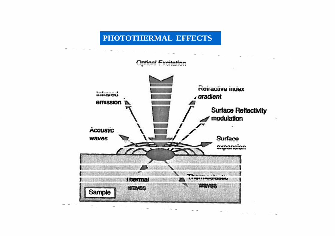
PHOTOTHERMAL EFFECTS
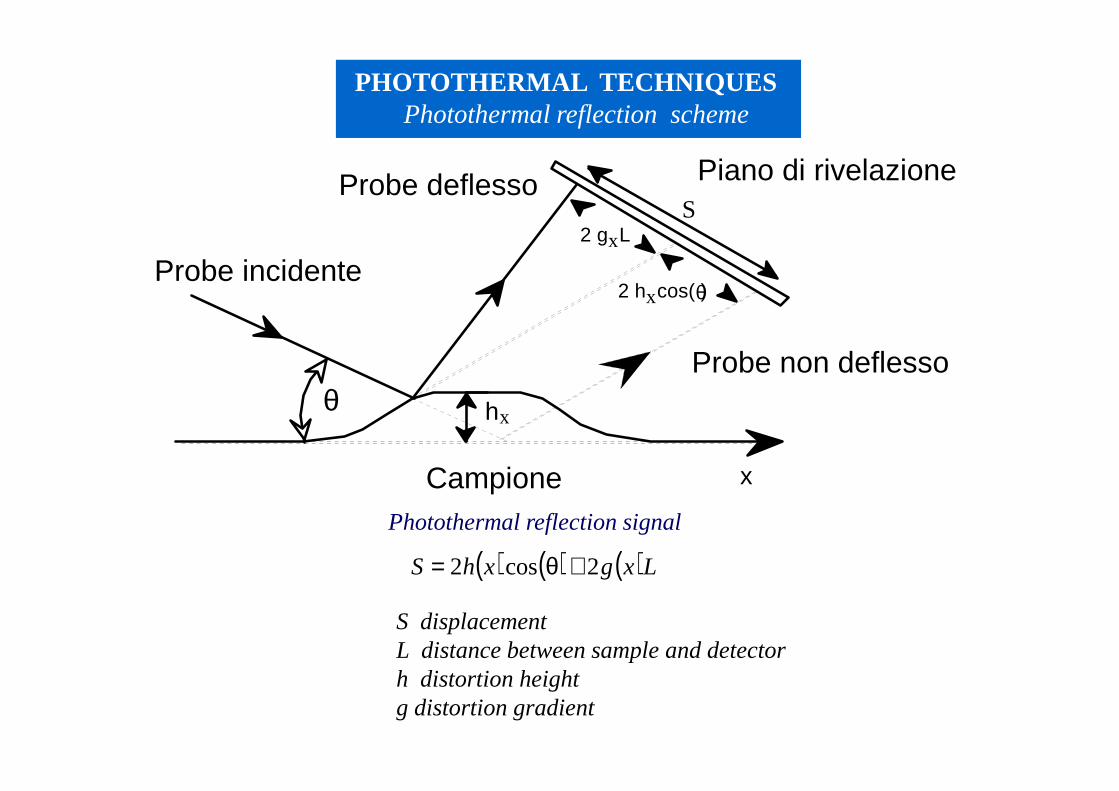
PHOTOTHERMAL TECHNIQUESPhotothermal reflection scheme
Probe incidente
Probe deflesso
Probe non deflesso
Piano di rivelazione
Campione
hx
x
2 h cos( )θx
2 g Lx
θ
S
( ) ( ) ( )LxgxhS 2cos2 +θ=
Photothermal reflection signal
S displacementL distance between sample and detectorh distortion height g distortion gradient
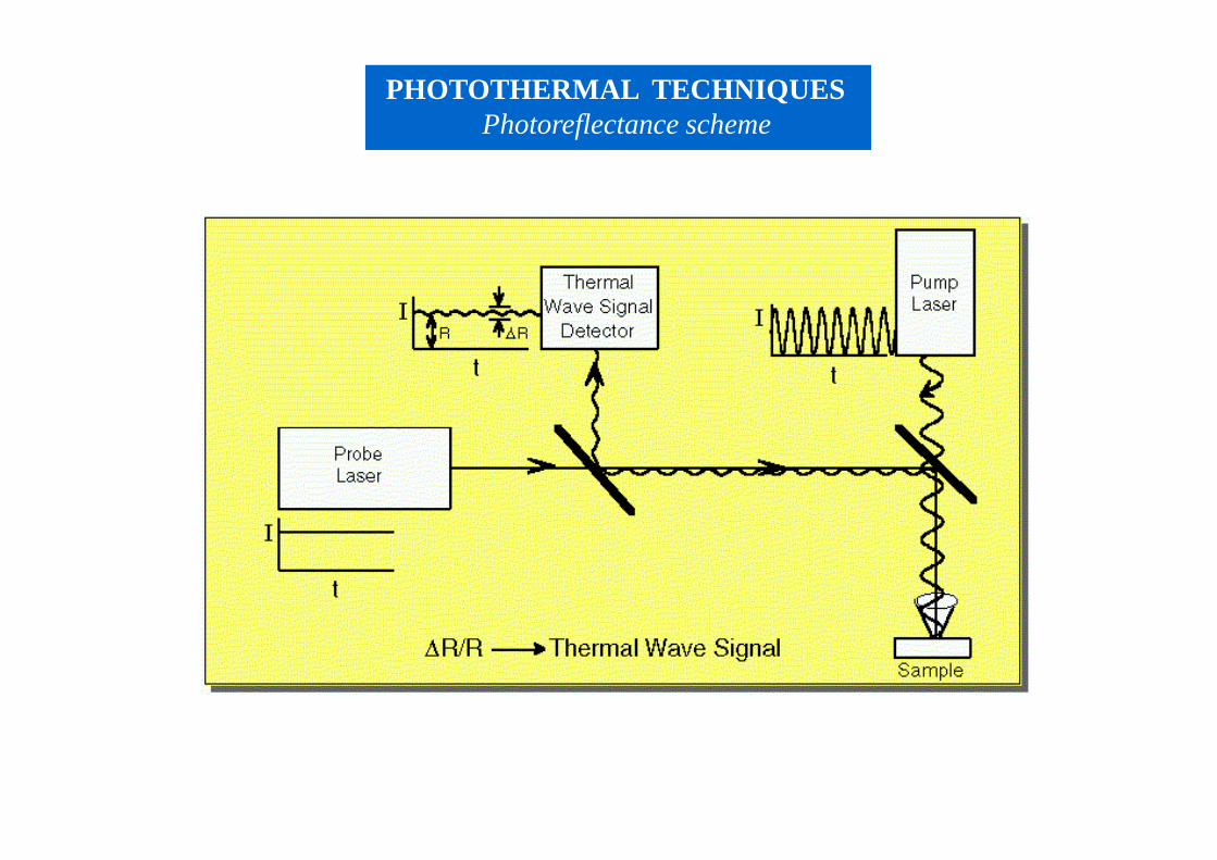
PHOTOTHERMAL TECHNIQUESPhotoreflectance scheme
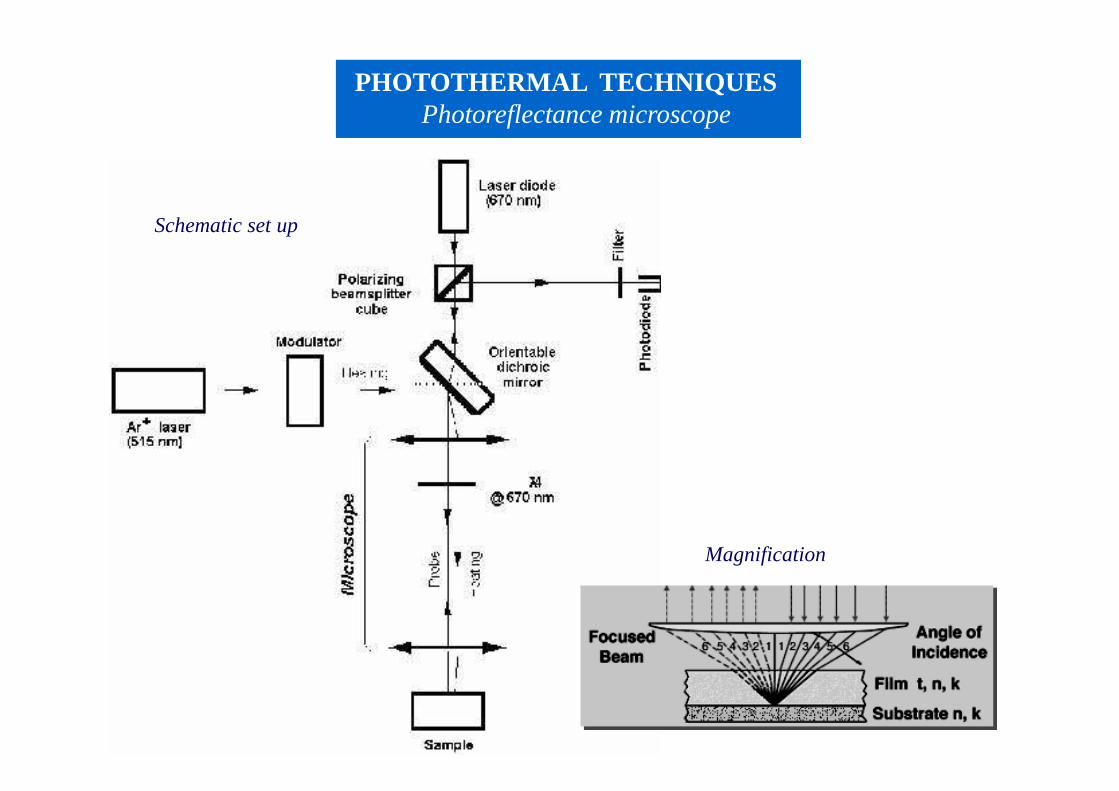
PHOTOTHERMAL TECHNIQUESPhotoreflectance microscope
Schematic set up
Magnification
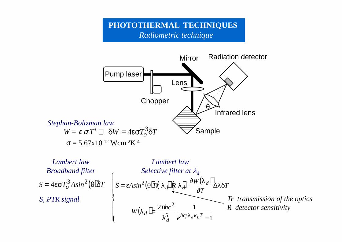
PHOTOTHERMAL TECHNIQUESRadiometric technique
Radiation detector
Sample
Chopper
Pump laser
Mirror
Lens
Infrared lensθ
( ) ( ) ( ) ( )
( )
−λπ=λ
λδ∆∂
λ∂λλθε=
λ 1
125
2
2
Tkhcd
d
ddd
Bde
hcW
TT
WRTrAsinS( ) TAsinTS o δθεσ= 234
TTW o δεσ=δ⇔ 34Stephan-Boltzman law
W = ε σ T4
σ = 5.67x10⁻¹² Wcm-2K-4
Lambert lawBroadband filter
Lambert lawSelective filter at λd
Tr transmission of the optics R detector sensitivity
S, PTR signal
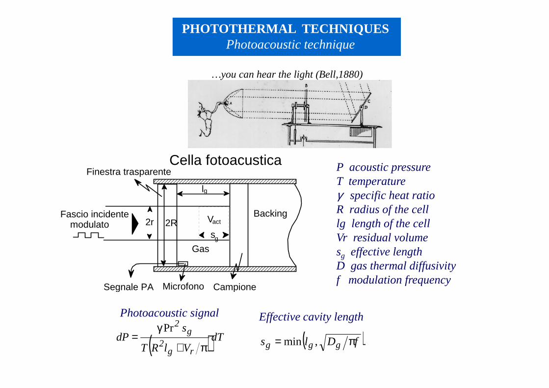
PHOTOTHERMAL TECHNIQUESPhotoacoustic technique
( )dTVlRT
sdP
rg2
g2
π+
γ=
Pr ( )fDls ggg π= ,min
P acoustic pressureT temperatureγ specific heat ratioR radius of the celllg length of the cellVr residual volumesg effective lengthD gas thermal diffusivityf modulation frequency
Backing
Segnale PA Microfono
Cella fotoacustica
2r 2R
lg
Campione
Finestra trasparente
Fascio incidentemodulato
Gas
Vact
sg
Photoacoustic signal Effective cavity length
…you can hear the light (Bell,1880)
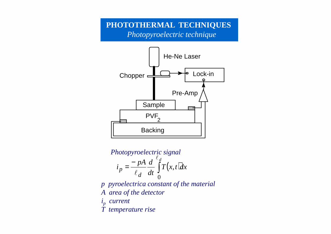
PHOTOTHERMAL TECHNIQUESPhotopyroelectric technique
He-Ne Laser
Sample
PVF2
Backing
Pre-Amp
Lock-inChopper
( )∫−=
d
dxtxTdt
dpAi
dp
l
l0
,
p pyroelectrica constant of the material A area of the detectorip currentT temperature rise
Photopyroelectric signal
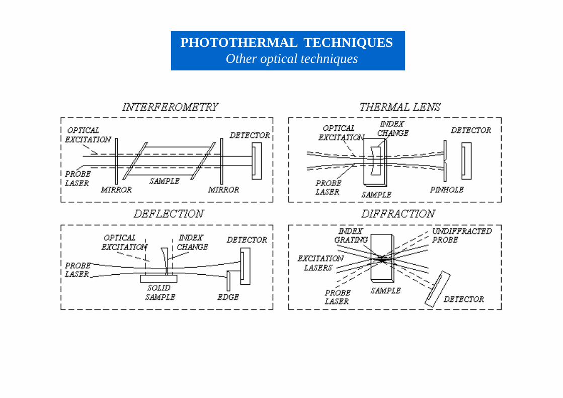
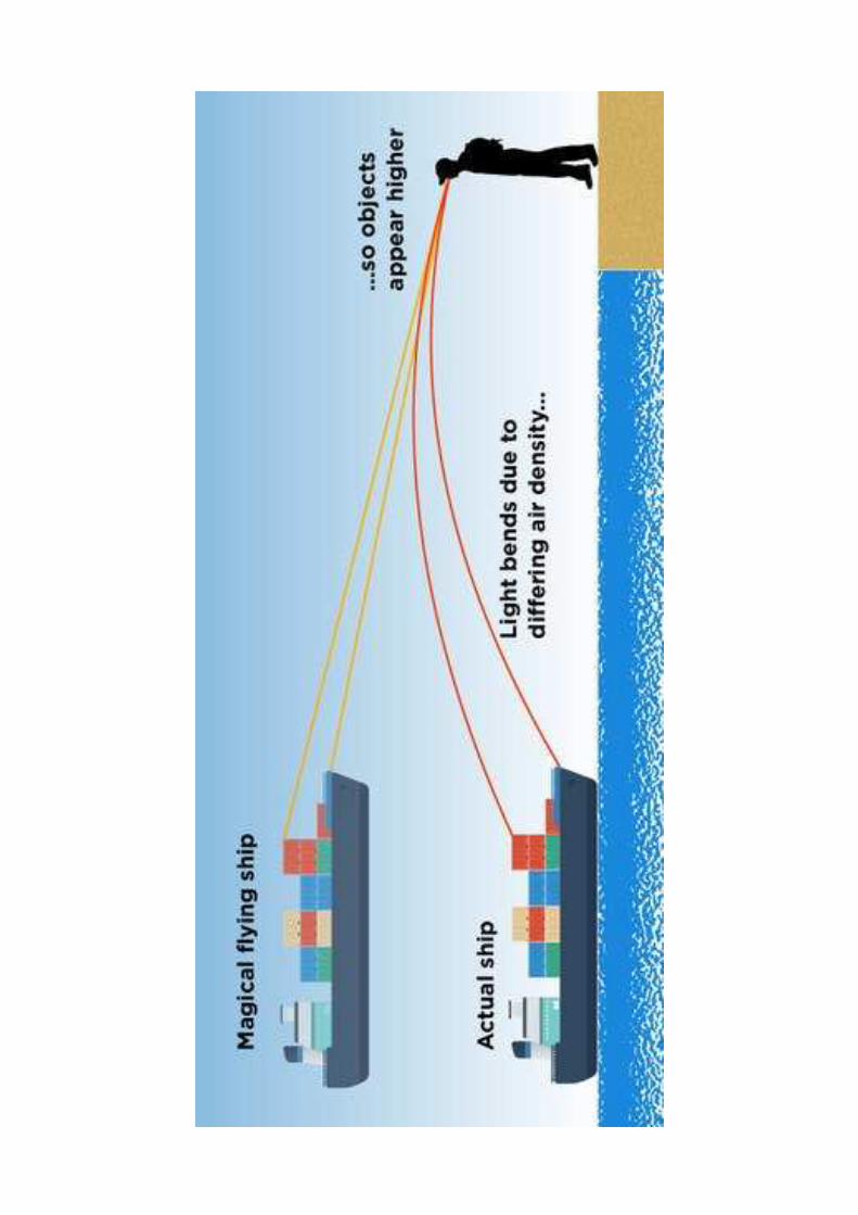
PHOTOTHERMAL TECHNIQUESOther optical techniques
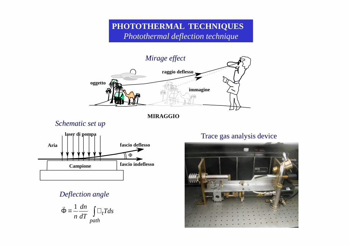
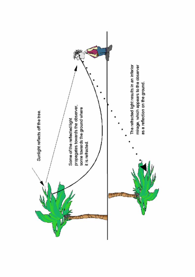
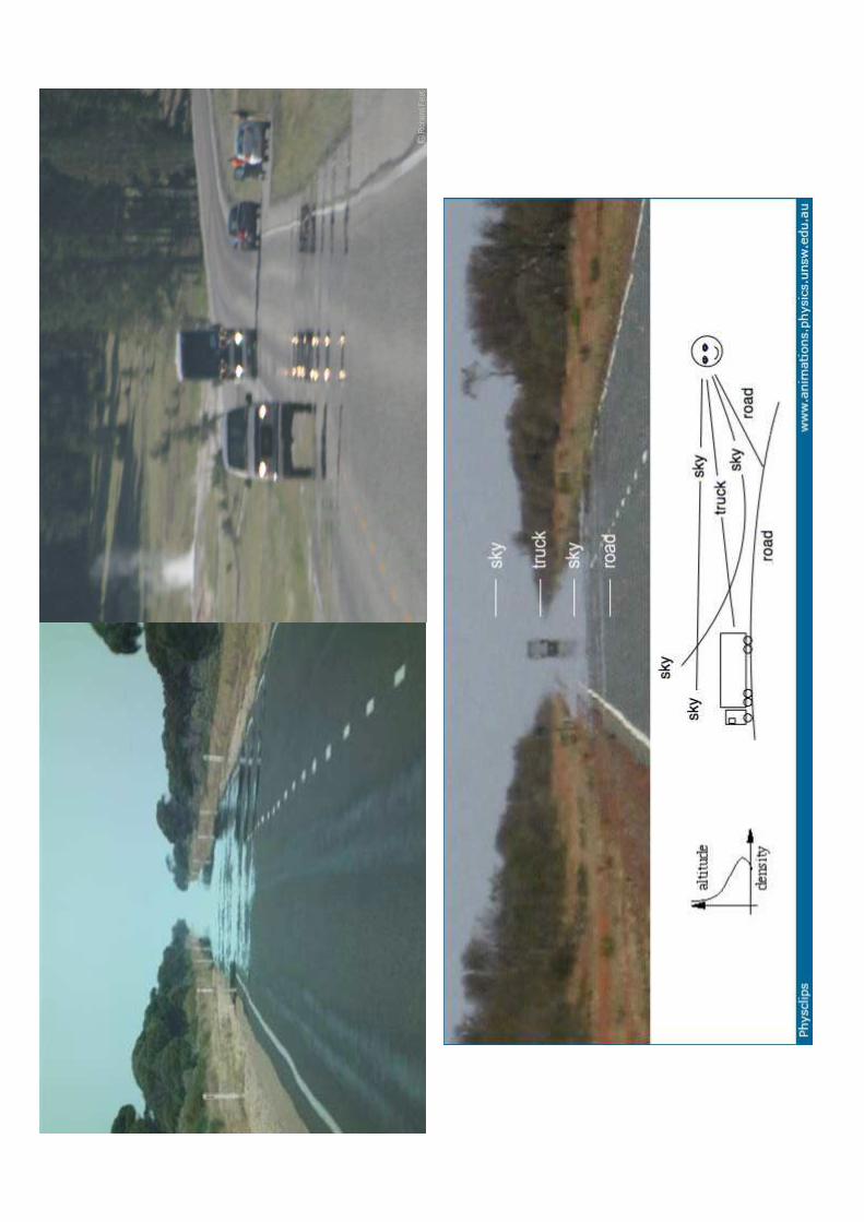
raggio deflesso
MIRAGGIO
oggettoimmagine
∫∇=Φpath
tTdsdT
dn
n
1r
laser di pompa
Φ
fascio deflesso
fascio indeflessoCampione
Aria
Trace gas analysis device
Mirage effect
Schematic set up
Deflection angle
PHOTOTHERMAL TECHNIQUESPhotothermal deflection technique


Photothermal deflectionM
irage
Optical Beam Deflection

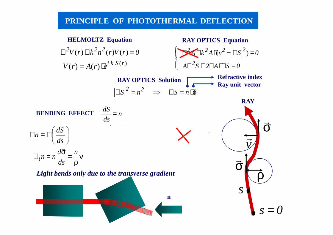
PRINCIPLE OF PHOTOTHERMAL DEFLECTION
0rVrnkrV 222 =+∇ )()()(
)()()( rS k ierArV ⋅=
=∇⋅∇+∇
=∇−⋅+∇
0SA2SA
0SnAkA
2
2222 )(
σ⋅=∇⇒=∇ rnS nS 22
nds
dS =
( ) νρ
σσσσ rrr
rr
n
ds
dn
ds
dn
ds
dn
ds
ndS
ds
d
ds
dSn +=+==∇=
∇=∇
νρ
=σ=∇r
rn
ds
dnnt
HELMOLTZ Equation RAY OPTICS Equation
RAY OPTICS Solution Refractive indexRay unit vector
σr
vr
σr
RAY
s
0s =
ρ
BENDING EFFECT
Light bends only due to the transverse gradient
n
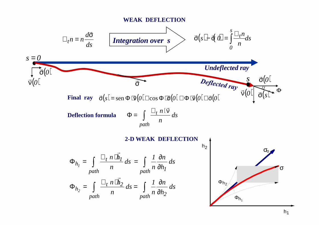
( ) ( ) ( ) ( ) ( )0000s σ+ν⋅Φ≅σ⋅Φ+ν⋅Φ=σ rrrvrcossen
∫ν⋅∇=Φ
path
t ds n
n r
h2
h1
Φ
Φh1
h2
σ
σ
o
∫∫
∫∫
∂∂=⋅∇=Φ
∂∂=⋅∇=Φ
path 2path
2th
path 1path
1th
ds h
n
n
1ds
n
hn
ds h
n
n
1 ds
n
hn
2
1
r
r
WEAK DEFLECTION
ds
dnnt
σ=∇r
Integration over s
σrUndeflected ray
( ) ( ) dsn
n0s
s
0
t∫∇=σ−σ rr
s
0s =
( )sσr
( )0σr
( )0νr
Final ray
2-D WEAK DEFLECTION
Deflection formula
( )0σr
( )0νr

∇⋅+
∇⋅=Φ
Φ++Φ+Φ=Φ
∑ ∫∫i path
t
ipath
t
f
n
T
nds
n
f ds
n
T
...
i
∂∂
∂∂r
rrrr
n1 ffT
)(...)()( 0nnn
0111
0 fff
nff
f
nTT
T
ndn −⋅
∂∂++−⋅
∂∂+−⋅
∂∂=
NATURE OF THE DEFLECTION
Taylor expansion of the refractive index
Photothermal deflection
∫∇=Φpath
tdT
dn
ndsT
1r
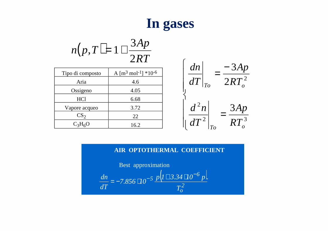
( )RT
ApTpn
2
31, +=
Tipo di composto A [m3 mol-1] *10-6
Aria 4.6
Ossigeno 4.05
HCl 6.68
Vapore acqueo 3.72 CS2 22
C3H6O 16.2
( )2o
65
T
p103431p108567
dT
dn −− ⋅+⋅−= .
.
AIR OPTOTHERMAL COEFFICIENT
Best approximation
In gases
=
−=
32
2
2
3
2
3
oTo
oTo
RT
Ap
dT
nd
RT
Ap
dT
dn
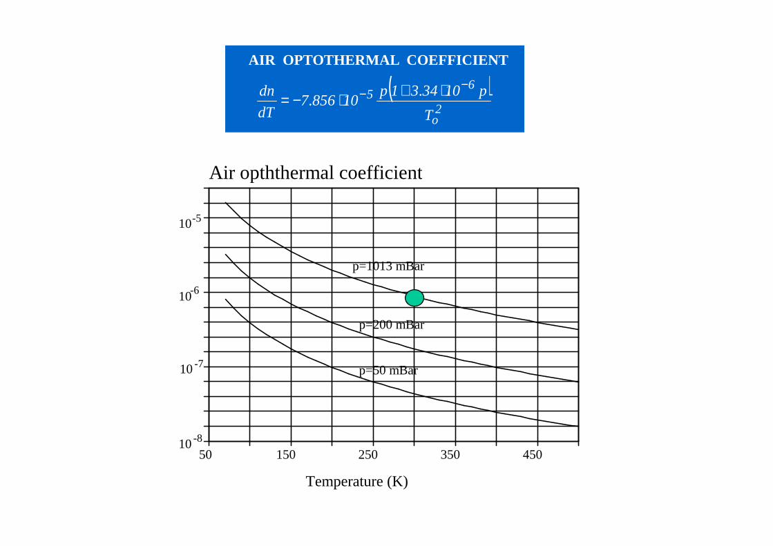
50 150 250 350 450
-5
-6
-8
p=1013 mBar
p=200 mBar
p=50 mBar
Temperature (K)
Air opththermal coefficient
10
10
-710
10
( )2o
65
T
p103431p108567
dT
dn −− ⋅+⋅−= .
.
AIR OPTOTHERMAL COEFFICIENT
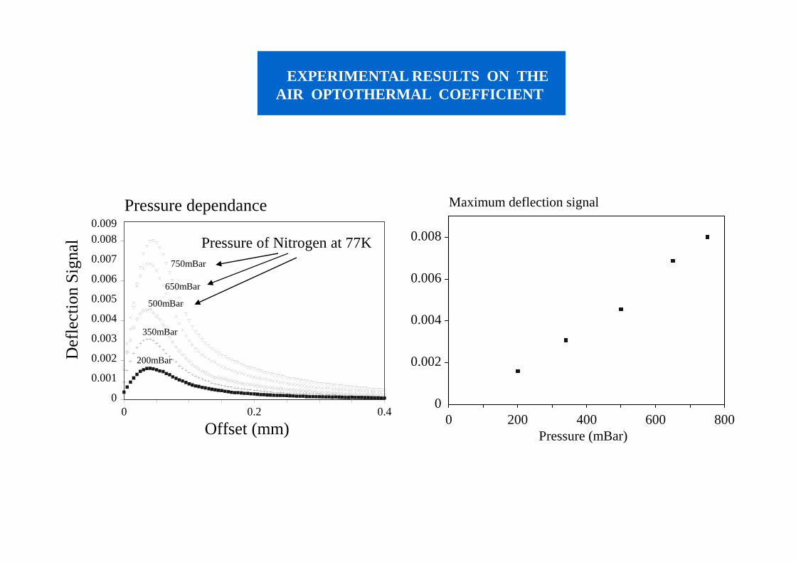
0 0.2 0.4
0.0090.008
0.007
0.006
0.005
0.004
0.003
0.002
0.001
0
Offset (mm)
Pressure dependance
750mBar
650mBar
500mBar
350mBar
200mBar
0 200 400 600 800
0.008
0.006
0.004
0.002
0
Pressure (mBar)
Maximum deflection signal
De
flect
ion
Sig
nal
Pressure of Nitrogen at 77K
EXPERIMENTAL RESULTS ON THEAIR OPTOTHERMAL COEFFICIENT
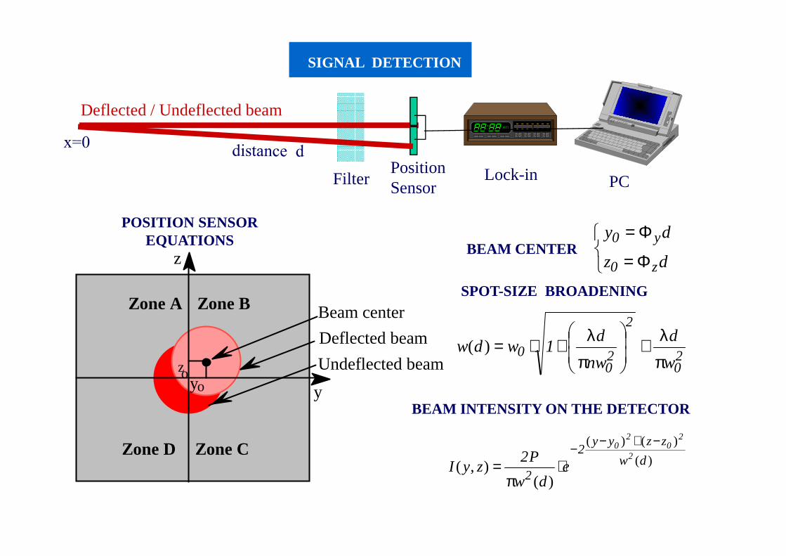
SIGNAL DETECTION
Φ=
Φ=
dz
dy
z0
y0
20
2
20
0w
d
nw
d1wdw
πλ≅
πλ+⋅=)(
)(
)()(
)(),( dw
zzyy2
2
2
20
20
edw
P2zyI
−+−−⋅
π=
FilterPositionSensor
Lock-in PC
Deflected / Undeflected beam
POSITION SENSOR EQUATIONS
BEAM CENTER
SPOT-SIZE BROADENING
BEAM INTENSITY ON THE DETECTOR
Zone A Zone B
Zone CZone D
Deflected beam
Beam center
Undeflected beamzoo y
z
y
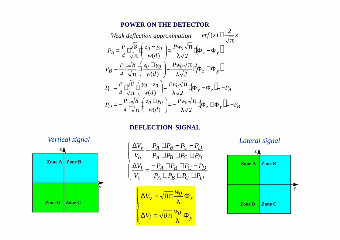
( )yz000
A2
Pw
dw
yz8
4
PP Φ−Φ⋅
λπ=
−⋅π
⋅=)(
( )yz000
B2
Pw
dw
yz8
4
PP Φ+Φ⋅
λπ=
+⋅π
⋅=)(
( ) Azy000
C P2
Pw
dw
zy8
4
PP −=Φ−Φ⋅
λπ=
−⋅π
⋅=)(
( ) Byz000
D P2
Pw
dw
yz8
4
PP −=Φ+Φ⋅
λπ−=
+⋅π
⋅−=)(
+++−++−=∆
+++−−+=∆
DCBA
DCBA
o
l
DCBA
DCBA
o
v
PPPP
PPPP
V
V
PPPP
PPPP
V
V
Φλ
π=∆
Φλ
π=∆
y0
l
z0
v
w8V
w8V
z2
zerfπ
≅)(
POWER ON THE DETECTOR
Weak deflection approximation
DEFLECTION SIGNAL
Zone A Zone B
Zone CZone D
y
z
Zone A Zone B
Zone CZone D
y
z
Lateral signalVertical signal
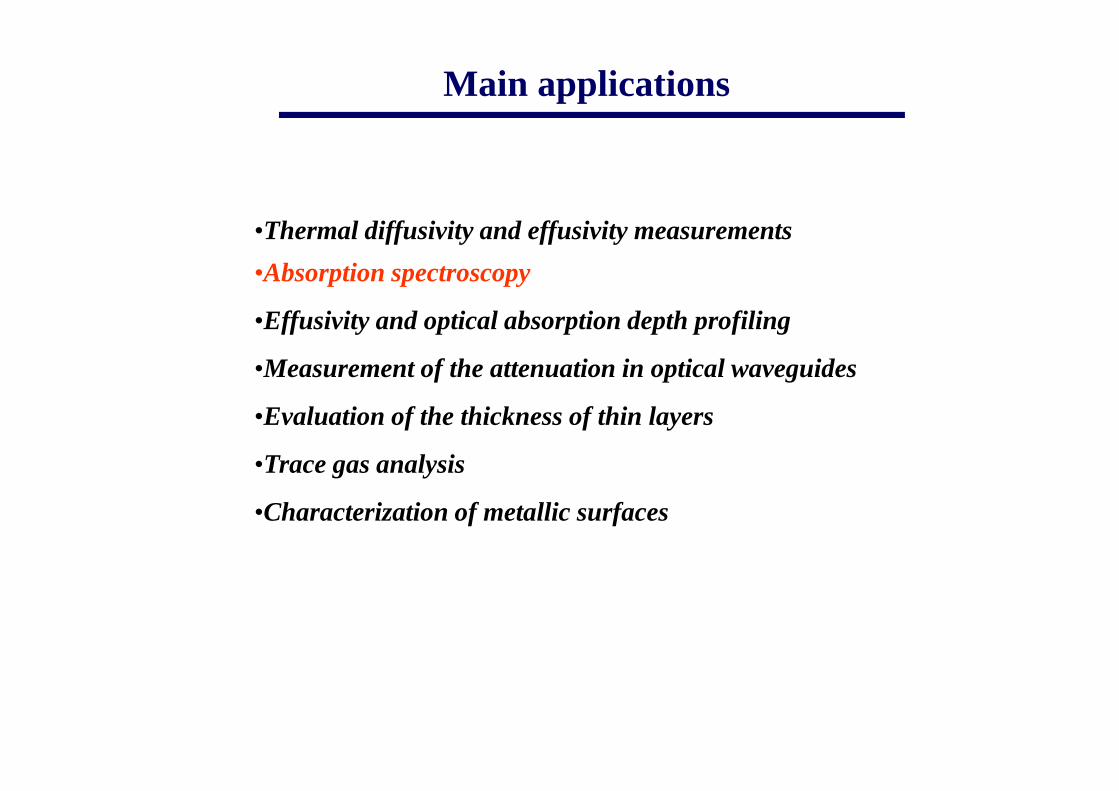
•Thermal diffusivity and effusivity measurements
•Absorption spectroscopy
•Effusivity and optical absorption depth profiling
•Measurement of the attenuation in optical waveguides
•Evaluation of the thickness of thin layers
•Trace gas analysis
•Characterization of metallic surfaces
Main applications
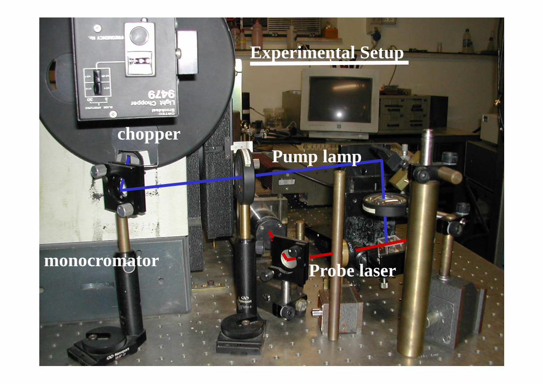
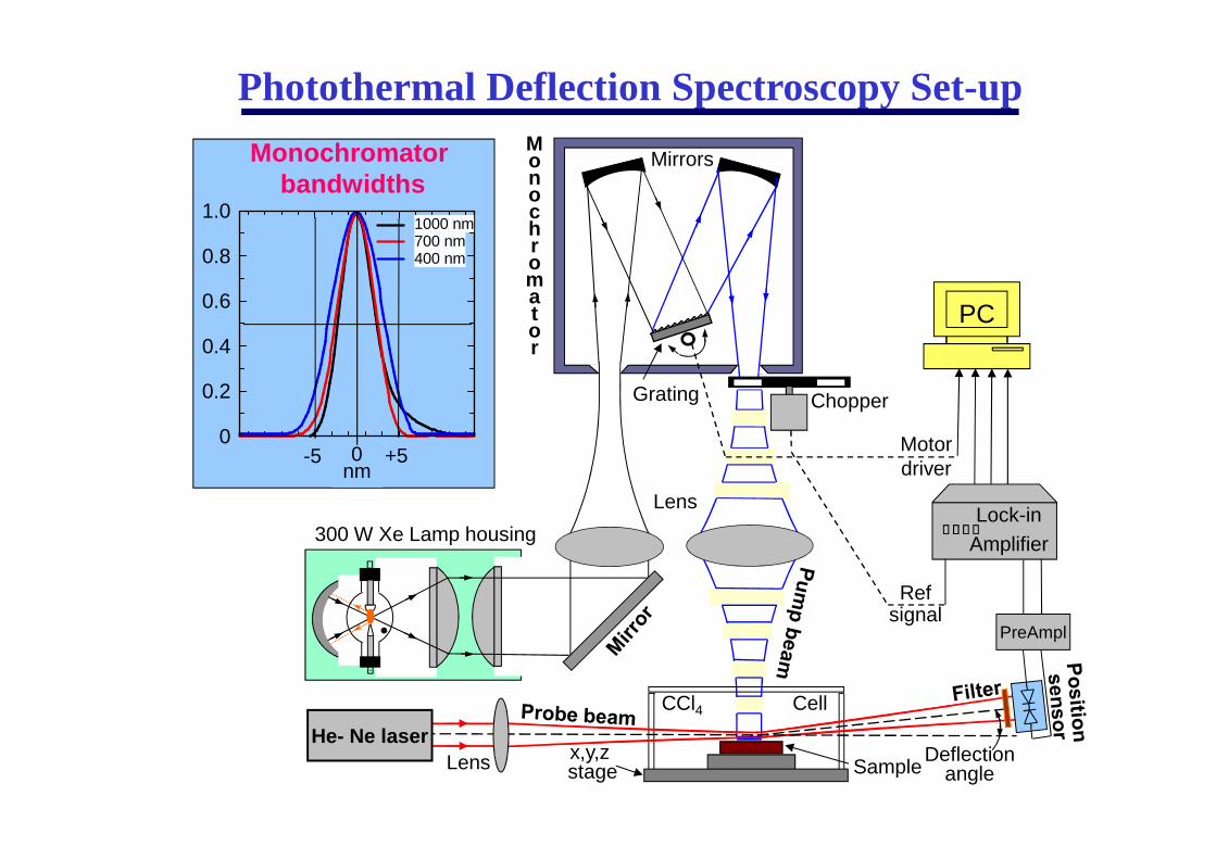
Experimental Setup
monocromator
chopperPump lamp
Probe laser
0
0.2
0.4
0.6
0.8
1.0
395 405
1000 nm700 nm400 nm
-5 0nm
+5
Monochromatorbandwidths
He- Ne laser
Mirrors
CCl4
300 W Xe Lamp housing
Lens
Lens
Deflectionangle
ChopperGrating
Sample
Cell
x,y,z stage
Monochromator
PC
Refsignal
PreAmpl
Motordriver
Lock-inAmplifier
Photothermal Deflection Spectroscopy Set-up
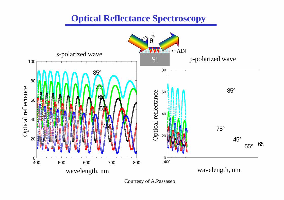
0
20
40
60
80
100
400 500 600 700 8000
20
40
60
80
400 5
s-polarized wavep-polarized wave
wavelength, nm wavelength, nm
Op
tical
ref
lect
ance
Op
tical
ref
lect
ance
45°
75°
55°
65°
85°
85°
75°
55° 6545°
Optical Reflectance Spectroscopy
θ
SiAlN
Courtesy of A.Passaseo

Photothermal Deflection Spectroscopy on AlN
0
0.2
0.4
0.6
0.8
1.0
400 500 600 700Wavelength, nm
Nor
mal
ized
Sig
nal,
a.u.
PDS
Optical reflectance 0°
calculated optical absorbance 0°θ
Si
AlN
probe
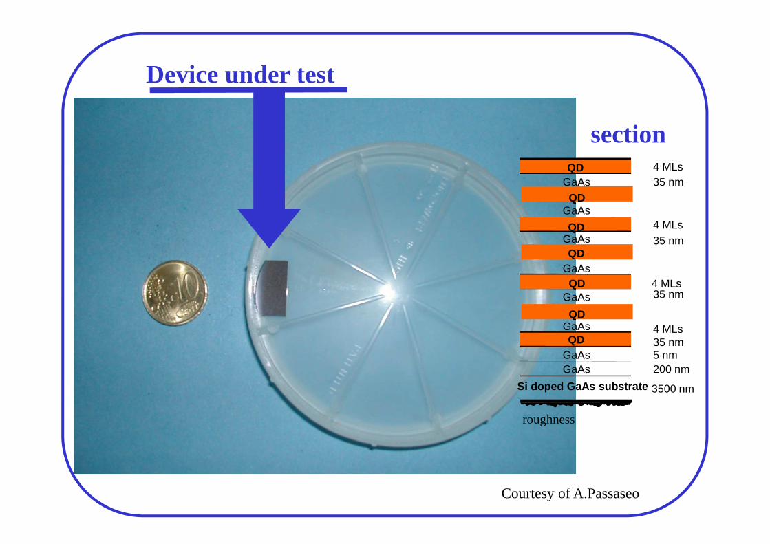
Device under test
4 MLsGaAs 35 nm
GaAs4 MLs
GaAs 35 nm
GaAs
GaAs 35 nm
GaAs 4 MLs35 nm
4 MLs
GaAs 5 nmGaAs 200 nm
Si doped GaAs substrate
QD
QD
QD
QD
QD
QD
QD
roughness
3500 nm
section
Courtesy of A.Passaseo
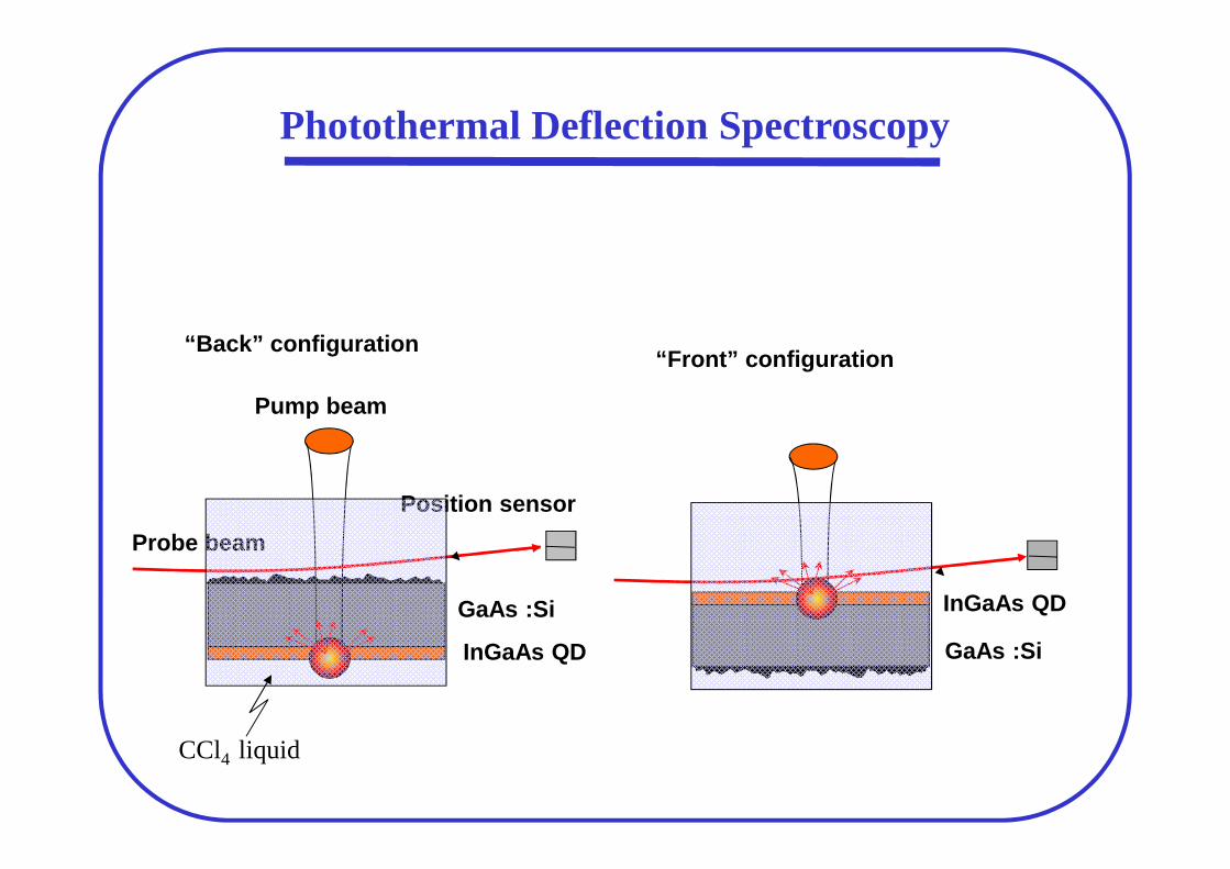
Position sensor
Pump beam
Probe beam
InGaAs QD
GaAs :Si
“Back” configuration
InGaAs QD
GaAs :Si
“Front” configuration
Photothermal Deflection Spectroscopy
CCl4 liquid

-40
-30
-20
-10
0
10
800 900 1000 1100 1200
QD fronteQD retroGaAs fronte
Wavelength, nm
Pha
se, d
eg.
PTD, QD-InGaAs/GaA-SI
0.05
0.1
0.2
0.5
1
800 900 1000 1100 1200
QD fronteQD retroGaAs-SI wafer
Wavelength, nm
Def
lect
ion
sign
al, a
.u.
PDS, QD-InGaAs/GaA-SI
Experimental Results on Quantum Dots
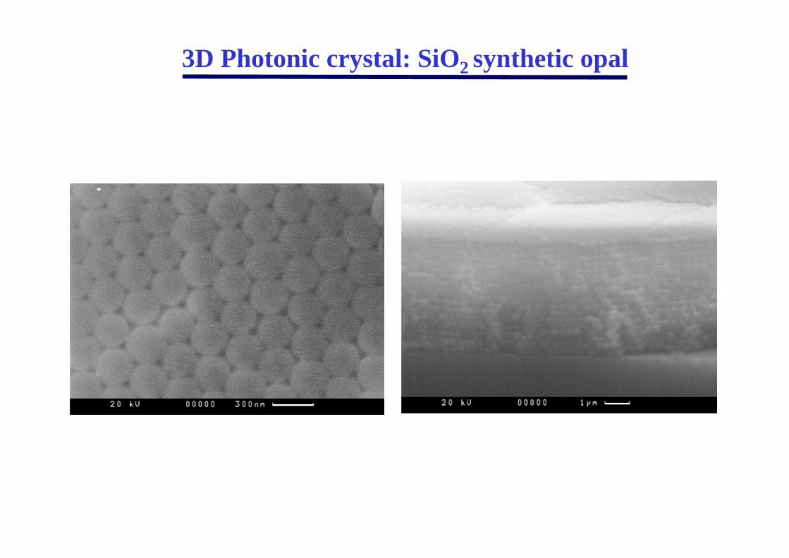
3D Photonic crystal: SiO2 synthetic opal
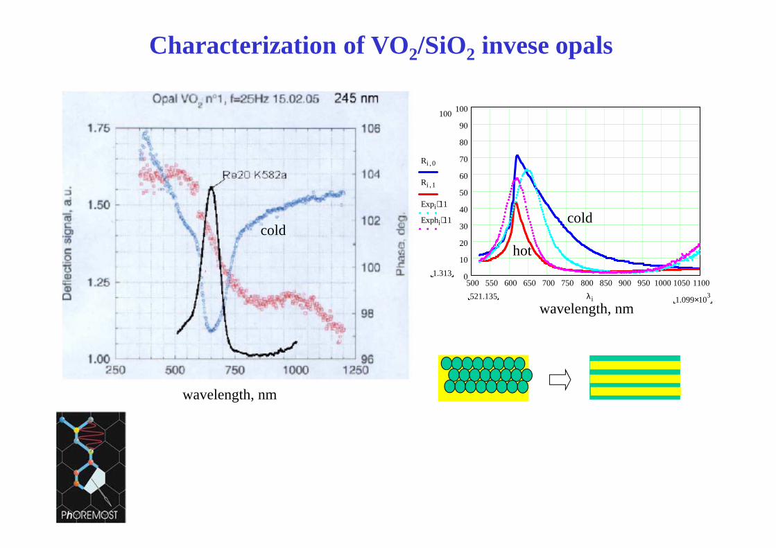
Characterization of VO2/SiO2 invese opals
500 550 600 650 700 750 800 850 900 950 1000 1050 11000
10
20
30
40
50
60
70
80
90
100100
1.313
Ri 0,
Ri 1,
Expi 11⋅
Exphi 11⋅
1.099 103×521.135 λi
wavelength, nm
wavelength, nm
hot
coldcold
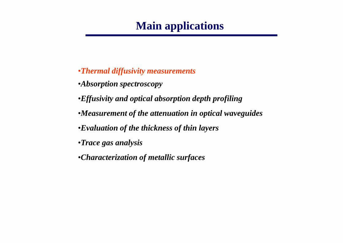
•Thermal diffusivity measurements
•Absorption spectroscopy
•Effusivity and optical absorption depth profiling
•Measurement of the attenuation in optical waveguides
•Evaluation of the thickness of thin layers
•Trace gas analysis
•Characterization of metallic surfaces
Main applications
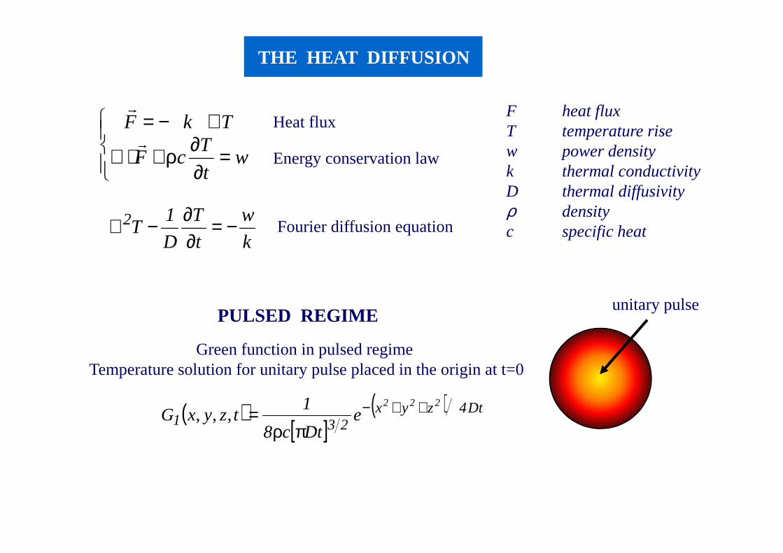
THE HEAT DIFFUSION
=∂∂ρ+⋅∇
∇−=
wt
TcF
TkFr
rHeat flux
Energy conservation law
k
w
t
T
D
1T2 −=
∂∂−∇ Fourier diffusion equation
F heat fluxT temperature risew power densityk thermal conductivityD thermal diffusivityρ densityc specific heat
( )[ ]
( ) Dt4zyx231
222
eDtc8
1tzyxG ++−
πρ=,,,
Green function in pulsed regime Temperature solution for unitary pulse placed in the origin at t=0
PULSED REGIMEunitary pulse
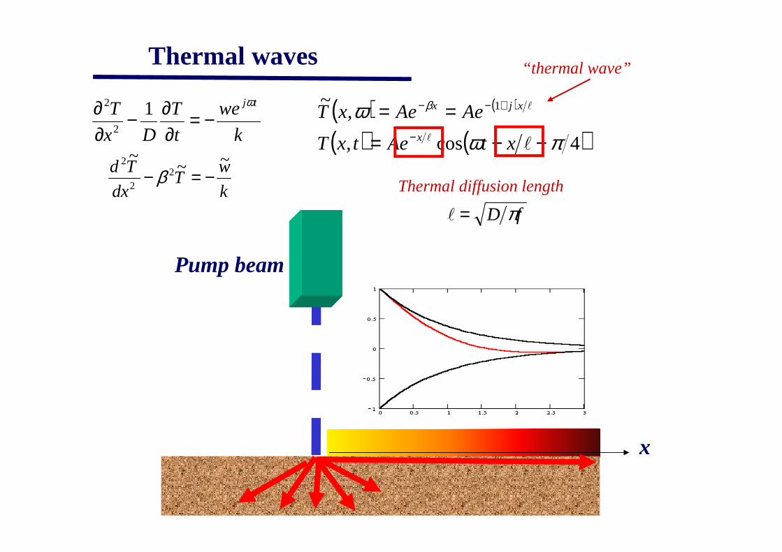
“thermal wave”
( ) ( )
( ) ( )4cos,
,~ 1
πωω β
−−===
−
+−−
ll
l
xtAetxT
AeAexTx
xjx
fD π=l
Thermal diffusion lengthk
wT
dx
Td ~~~
22
2
−=− β
Pump beam
k
we
t
T
Dx
T tjω
−=∂∂−
∂∂ 1
2
2
x
Thermal waves
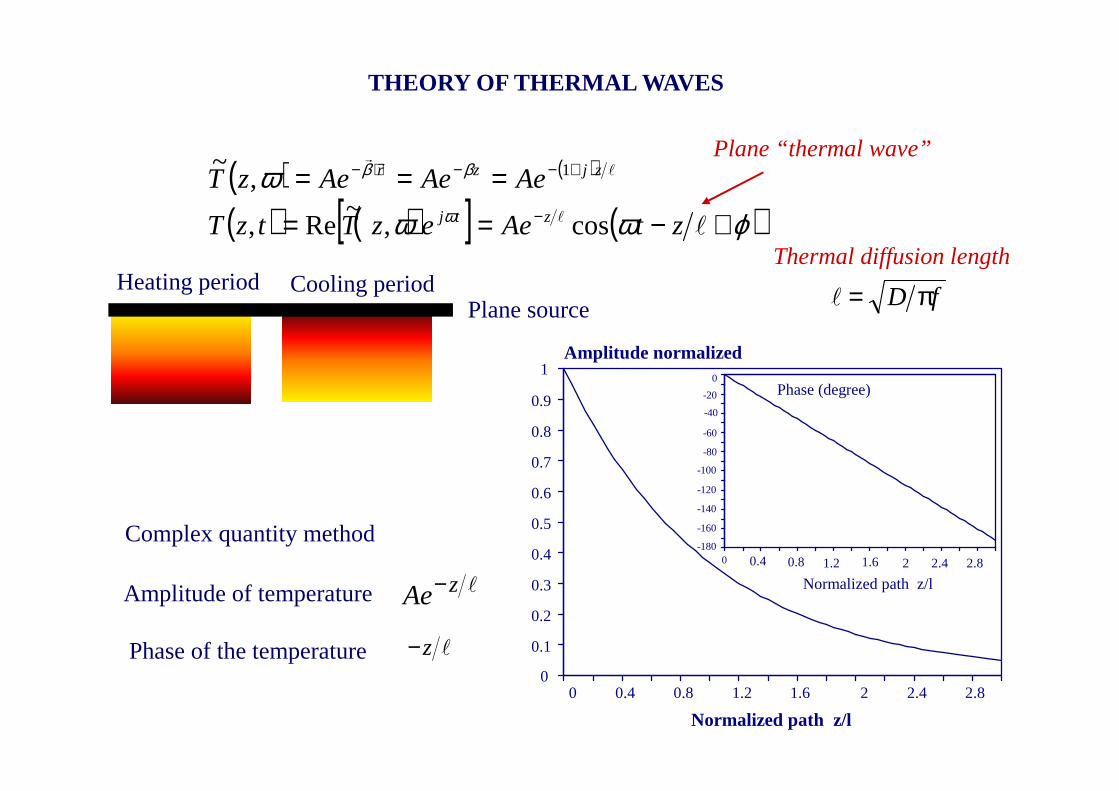
THEORY OF THERMAL WAVES
Heating period Cooling period
Plane “thermal wave”( ) ( )
( ) ( )[ ] ( )ϕωωω
ω
ββ
+−==
===−
+−−⋅−
ll
lrr
ztAeezTtzT
AeAeAezTztj
zjzr
cos,~
Re,
,~ 1
Plane source
Amplitude of temperature
Phase of the temperature
lzAe−
lz−
Complex quantity method
0 0.4 0.8 1.2 1.6 2 2.4 2.8
1
0.9
0.8
0.7
0.6
0.5
0.4
0.3
0.2
0.1
0
0 0.4 0.8 1.2 1.6 2 2.4 2.8
0
-20
-40
-60
-80
-100
-120
-140
-160
-180
Normalized path z/l
Phase (degree)
Amplitude normalized
Normalized path z/l
fD π=l
Thermal diffusion length
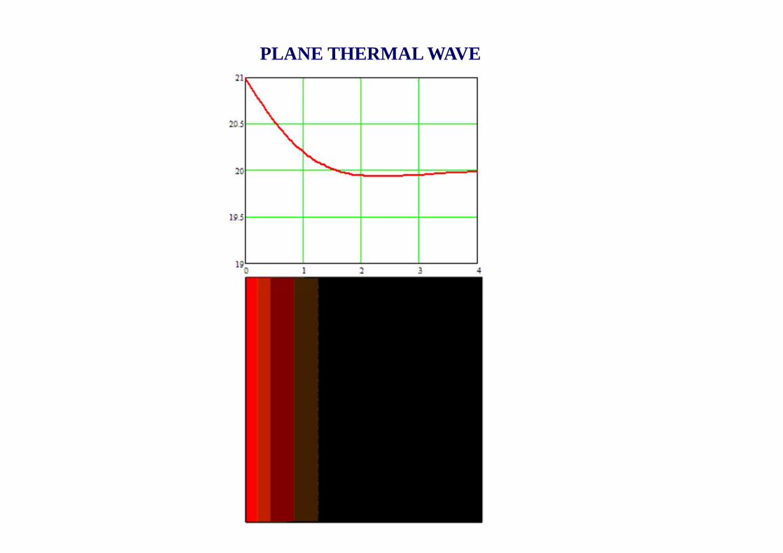
PLANE THERMAL WAVE
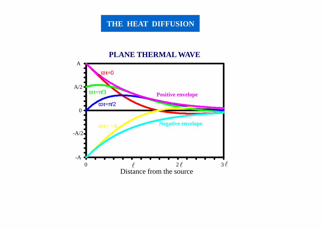
PLANE THERMAL WAVE
0 2 3
A
A/2
0
-A
-A/2
Distance from the source
Negative envelope
Positive envelope
ω t=π/2
ω t=π/3
ω t=0
ω t= −π
l l l
THE HEAT DIFFUSION
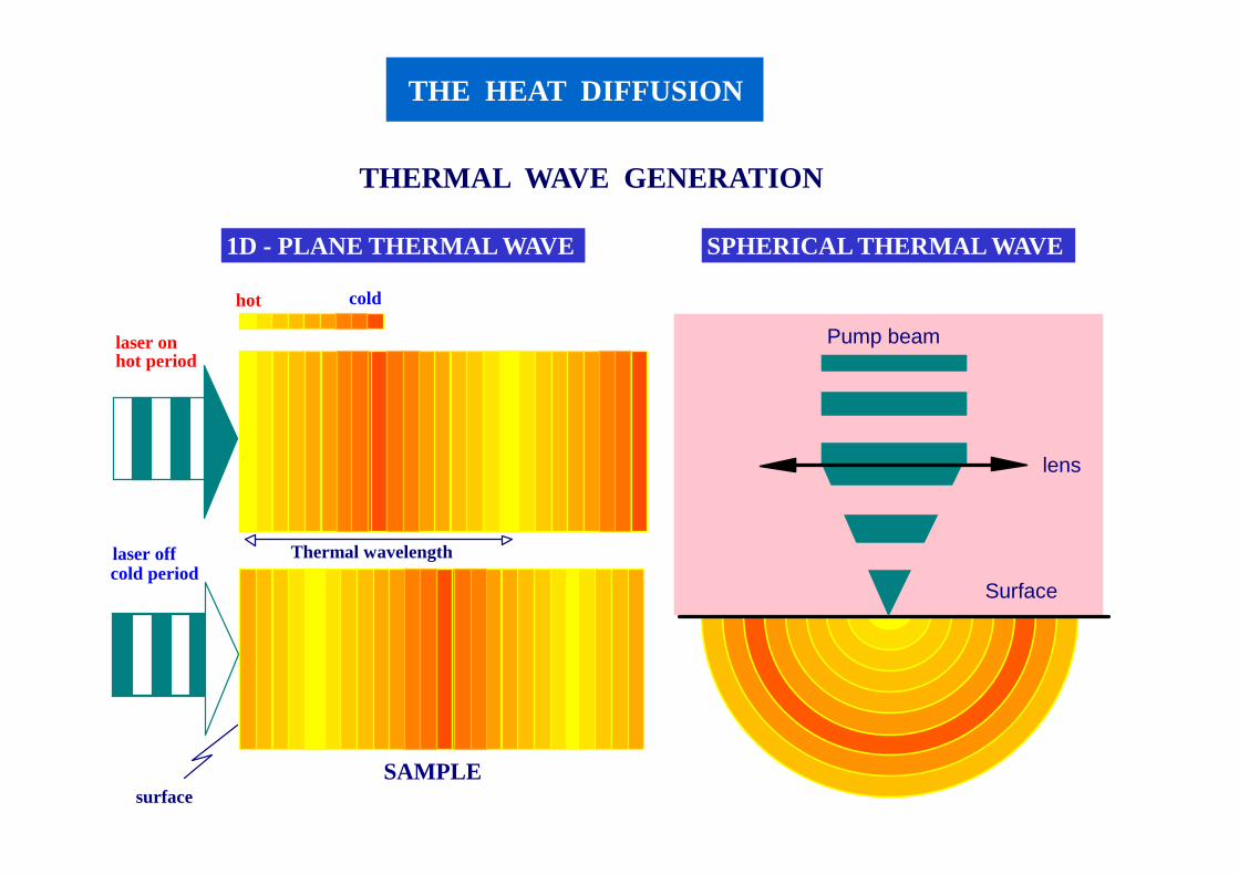
THERMAL WAVE GENERATION
Pump beam
lens
Surface
coldhot
hot period
cold period
laser on
laser off Thermal wavelength
surfaceSAMPLE
1D - PLANE THERMAL WAVE SPHERICAL THERMAL WAVE
THE HEAT DIFFUSION
Plane “thermal wave”
( ) ( )l
zjz
D
jz eAeAeAzT
+−⋅−− ⋅=⋅=⋅=
1,
~ω
βω fD π=l
Thermal diffusion length
0~
~
2
2
=
− TD
j
dz
Td ω
IThdz
Tdk
z
=+−=
~~
0
( ) IAhk =⋅+⋅ βhk
IA
+=
β
( ) ( ) lzj
g
zD
j
g
zD
jz e
je
Ie
je
Ie
hD
jk
Ie
hk
IzT +−
⋅−⋅−− ⋅=⋅≈⋅
+=⋅
+= 1,
~
ωωωβω
ωωβ
( ) ( )[ ]
−−== −
4cos,
~Re,
πωω
ω ω
l
l zte
e
IezTtzT z
g
tj
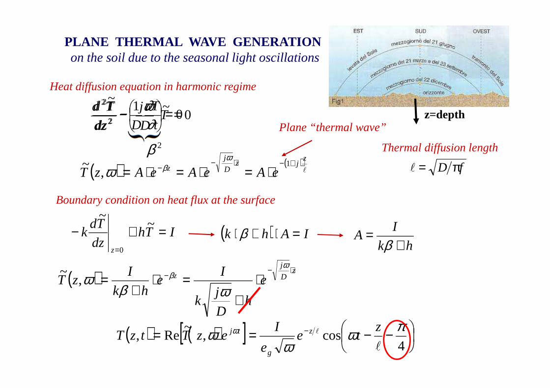
PLANE THERMAL WAVE GENERATIONon the soil due to the seasonal light oscillations
Boundary condition on heat flux at the surface
Heat diffusion equation in harmonic regime
2β
z=depth01
2
2
=−t
T
Ddz
Td
∂∂

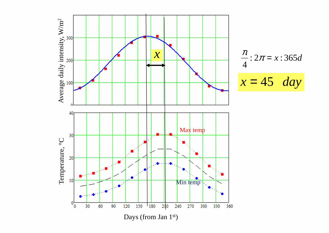
Days (from Jan 1st)
Tem
pera
ture
, °C
Max temp
Min temp
Ave
rage
da
ily in
tens
ity, W
/m2dx 365:2:
4=ππ
dayx 45=
x
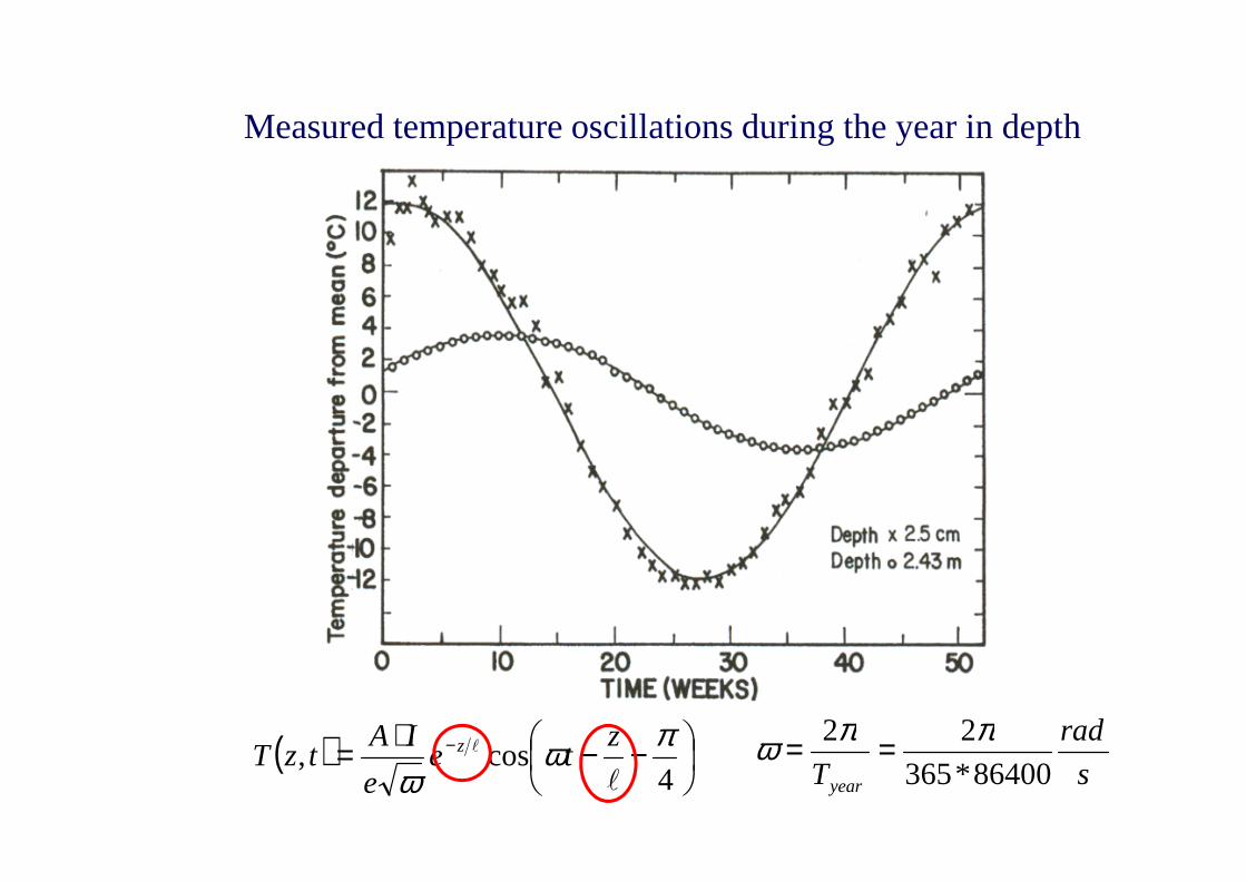
Measured temperature oscillations during the year in depth
( )
−−⋅= −
4cos,
πωω l
l zte
e
IAtzT z
s
rad
Tyear 86400*365
22 ππω ==
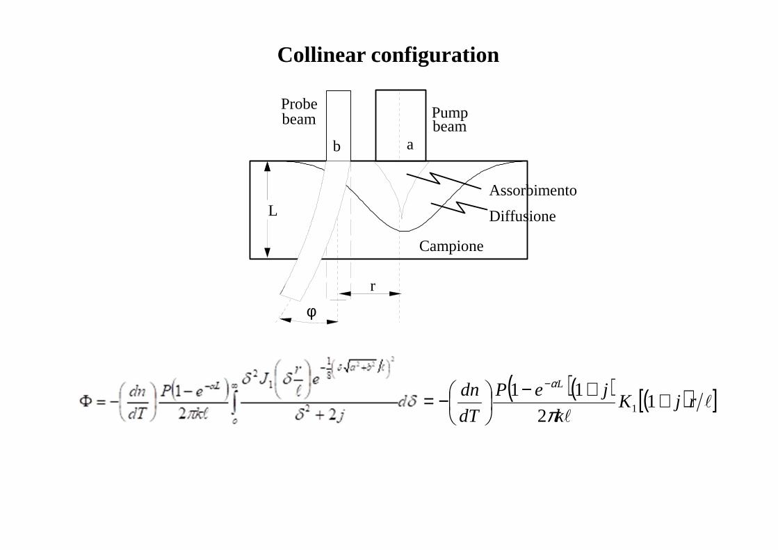
L
r
φ
Pumpbeambeam
Probe
Campione
ab
Diffusione
Assorbimento
( )( ) ( )[ ]ll
rjKk
jeP
dT
dn L
++−
−=−
12
111π
α
Collinear configuration
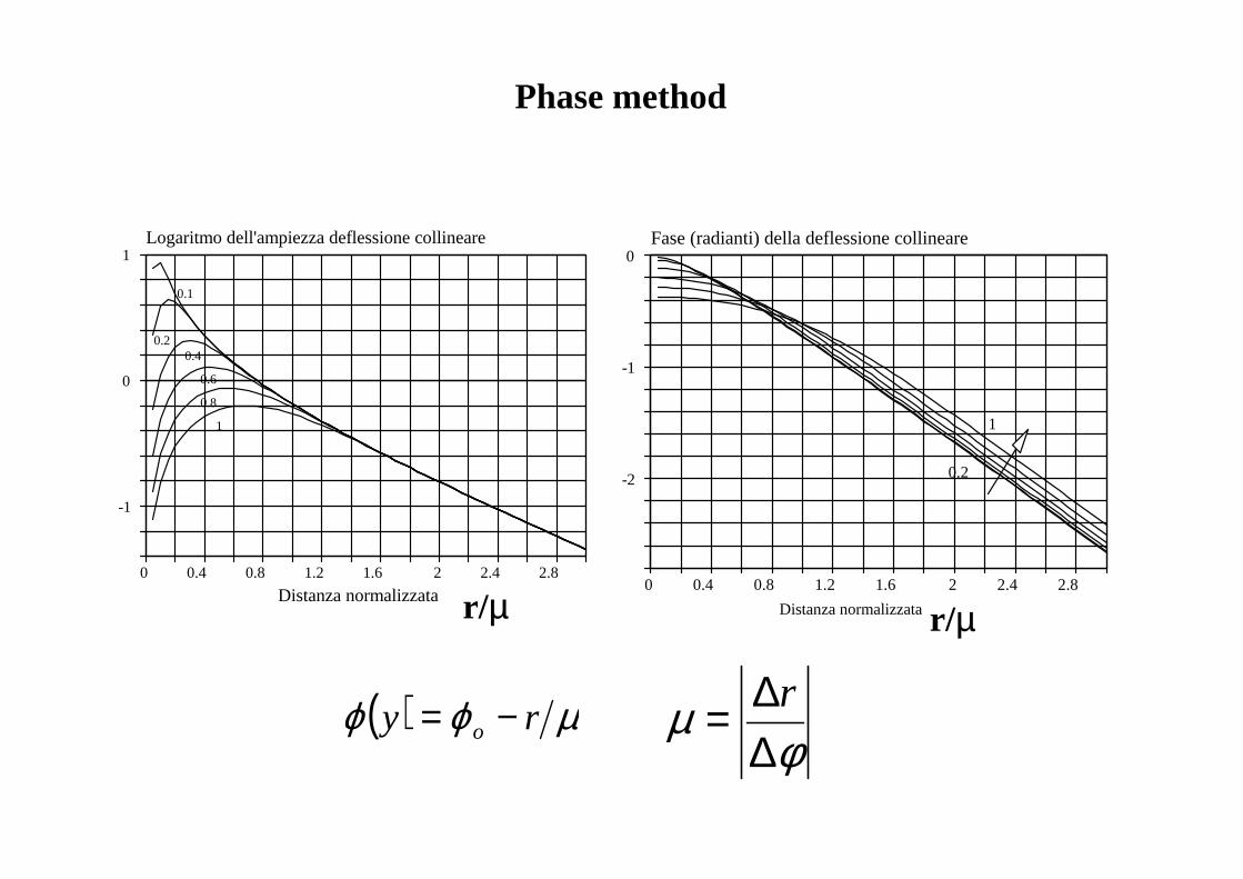
0 0.4 0.8 1.2 1.6 2 2.4 2.8
0
-1
-2
Fase (radianti) della deflessione collineare
Distanza normalizzata
0.2
1
r/µ0 0.4 0.8 1.2 1.6 2 2.4 2.8
1
0
-1
Distanza normalizzata
Logaritmo dell'ampiezza deflessione collineare
0.20.4
0.6
0.1
1
0.8
r/µ
φµ
∆∆= r
Phase method
( ) µϕϕ ry o −=
Z
Pump beam
Probe beam
n
t
x
Y
y
φ
φ
Vertical offset z
Sample
Vertical deflection
Lateral deflection
Lateral offset x
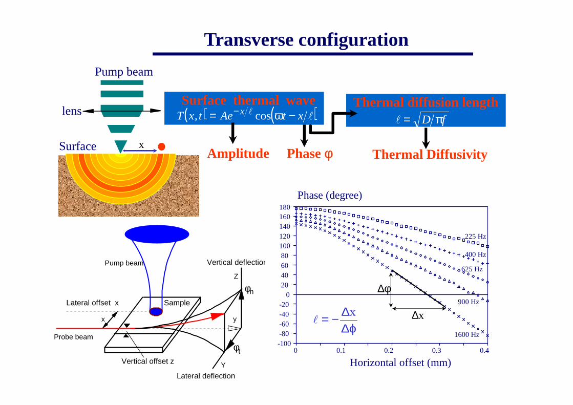
Transverse configuration
Pump beam
lens
Surface
( ) ( )T x t Ae t xx, cos= −− llω
Surface thermal wavel = D fπ
Phase φAmplitude
Thermal diffusion length
Thermal Diffusivity
0 0.1 0.2 0.3 0.4
18016014012010080604020
0-20-40-60-80-100
Phase (degree)
Horizontal offset (mm)
1600 Hz
900 Hz
625 Hz
400 Hz
225 Hz
ϕ∆∆−= x
l∆x
∆φ
x
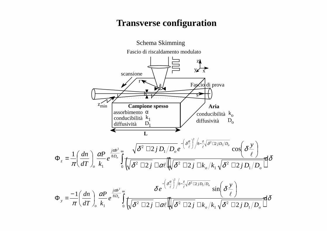
Transverse configuration
Schema Skimming
Campione spesso
Fascio di prova
Fascio di riscaldamento modulato
b
a
xy
z
s
L
zmin
scansione
assorbimento conducibilitàdiffusività
αk1D1
conducibilitàdiffusività
koDo
Aria
r
( )( ) δδδαδ
δδα
π
δδω
dDDjkkjj
yeDDj
ek
P
dT
dn
oo
DDjza
oD
bj
oz
o
o ∫∞
+−
−
+++++
+
=Φ0 1
21
22
28
12
8
1 222
cos21
12
2
2
l
l
ll
( )( ) δδδαδ
δδα
π
δδω
dDDjkkjj
ye
ek
P
dT
dn
oo
DDjza
D
bj
oy
o
o ∫∞
+−
−
+++++
−=Φ0 1
21
22
28
8
1 222
sin1
12
2
2
l
l
ll
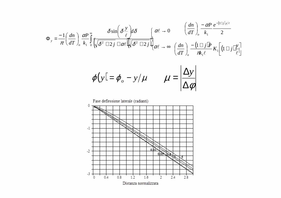
( )( )
( )
( ) ( )
++−
−
∞→
→
+++
−=Φ
+−
∞
∫
ll
l
l
l
l
l
yjK
k
Pj
dT
dn
e
k
P
dT
dn
jj
dy
k
P
dT
dn
o
yj
o
oy
11
20
22
sin1
11
1
1
022
1
π
α
α
α
δαδ
δδδα
π
φµ
∆∆= y( ) µϕϕ yy o −=
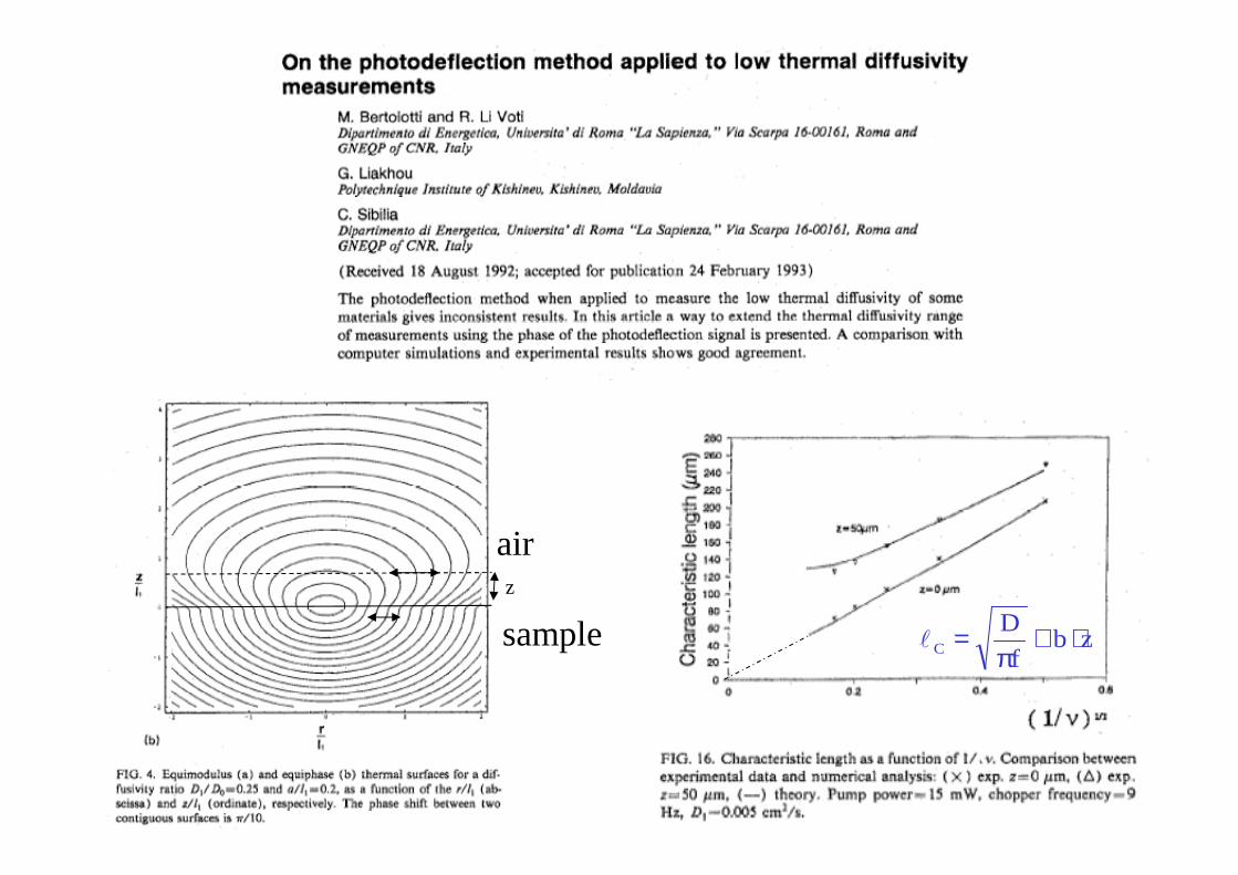
zbf
DC ⋅+
π=l
air
sample
z
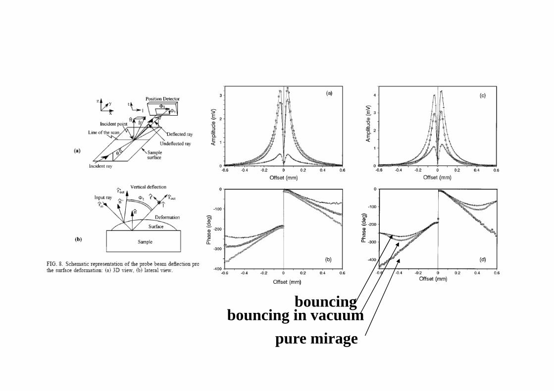
pure mirage
bouncing in vacuumbouncing
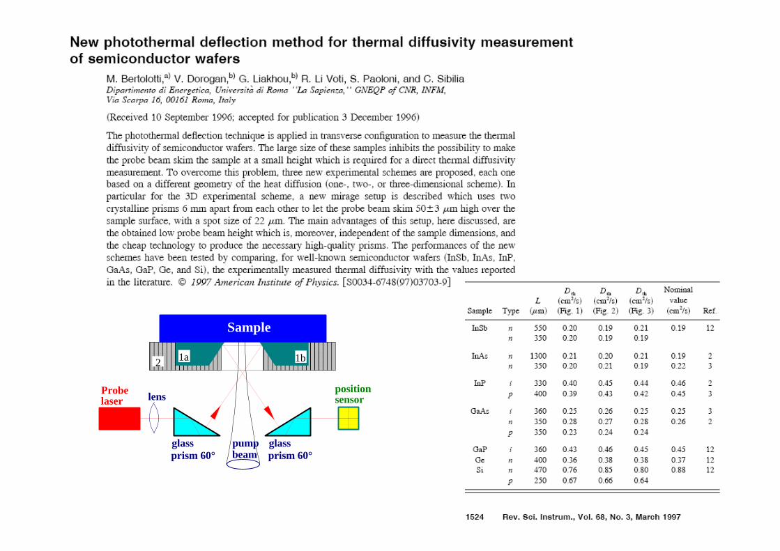
1a 1b
Sample
lensposition sensor
Probe laser
pumpbeam
2
prism 60° prism 60°glass glass
PROBE BEAM
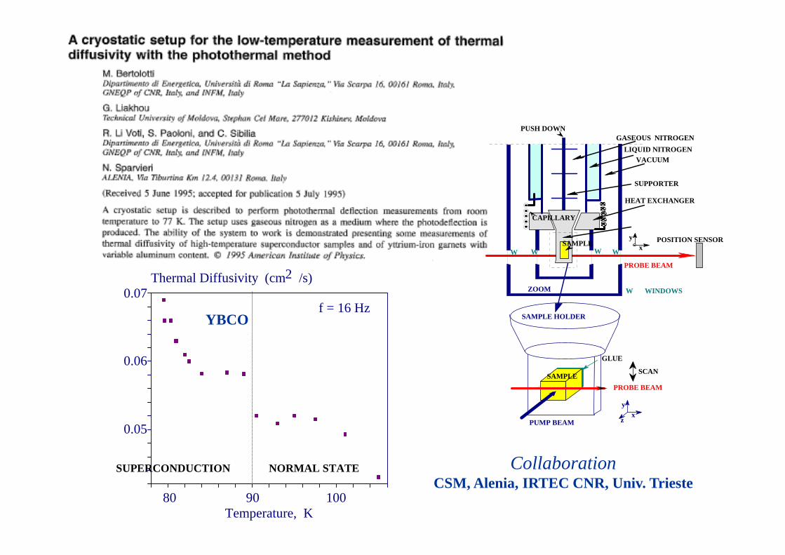
WW W
HEAT EXCHANGER
SUPPORTER
SAMPLE HOLDER
GASEOUS NITROGEN
POSITION SENSOR
W WINDOWS
xy
PUMP BEAM
SAMPLE
xz
CAPILLARY
VACUUMLIQUID NITROGEN
ZOOM
GLUE
PROBE BEAM
y
SAMPLE HOLDER
SCAN
PUSH DOWN
WSAMPLE
CollaborationCSM, Alenia, IRTEC CNR, Univ. Trieste
80 90 100
0.07
0.06
0.05
f = 16 Hz
Temperature, K
Thermal Diffusivity (cm /s)2
SUPERCONDUCTION NORMAL STATE
YBCO
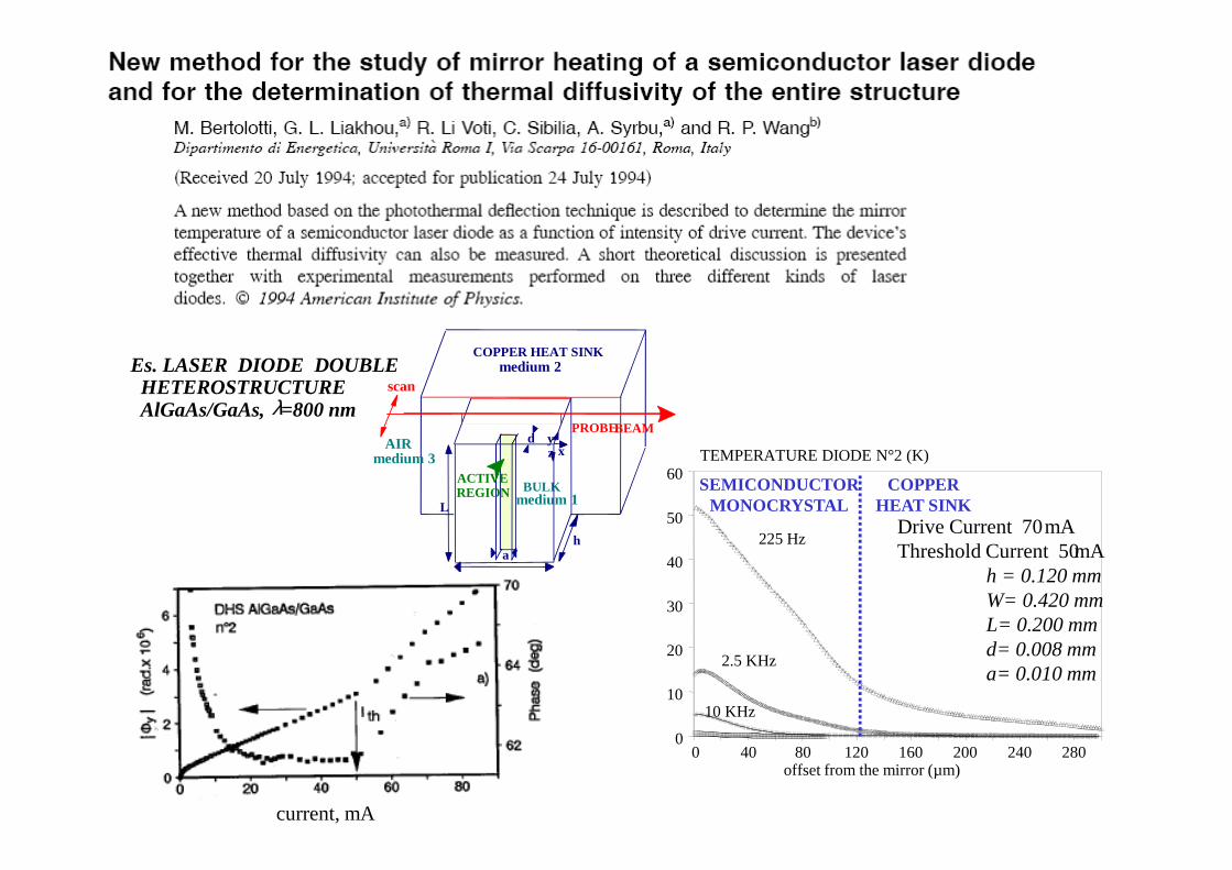
h
W
L
d
a
COPPER HEAT SINK
BULKACTIVEREGION
PROBE BEAM
zy
x
medium 2
medium 1
medium 3AIR
scan
0 40 80 120 160 200 240 280
TEMPERATURE DIODE N°2 (K)
offset from the mirror (µm)
60
50
40
30
20
10
0
10 KHz
2.5 KHz
225 Hz
COPPERHEAT SINK
SEMICONDUCTORMONOCRYSTAL
Drive Current 70 mAThreshold Current 50 mA
h = 0.120 mmW= 0.420 mmL= 0.200 mmd= 0.008 mma= 0.010 mm
Es. LASER DIODE DOUBLE HETEROSTRUCTUREAlGaAs/GaAs, λ=800 nm
current, mA
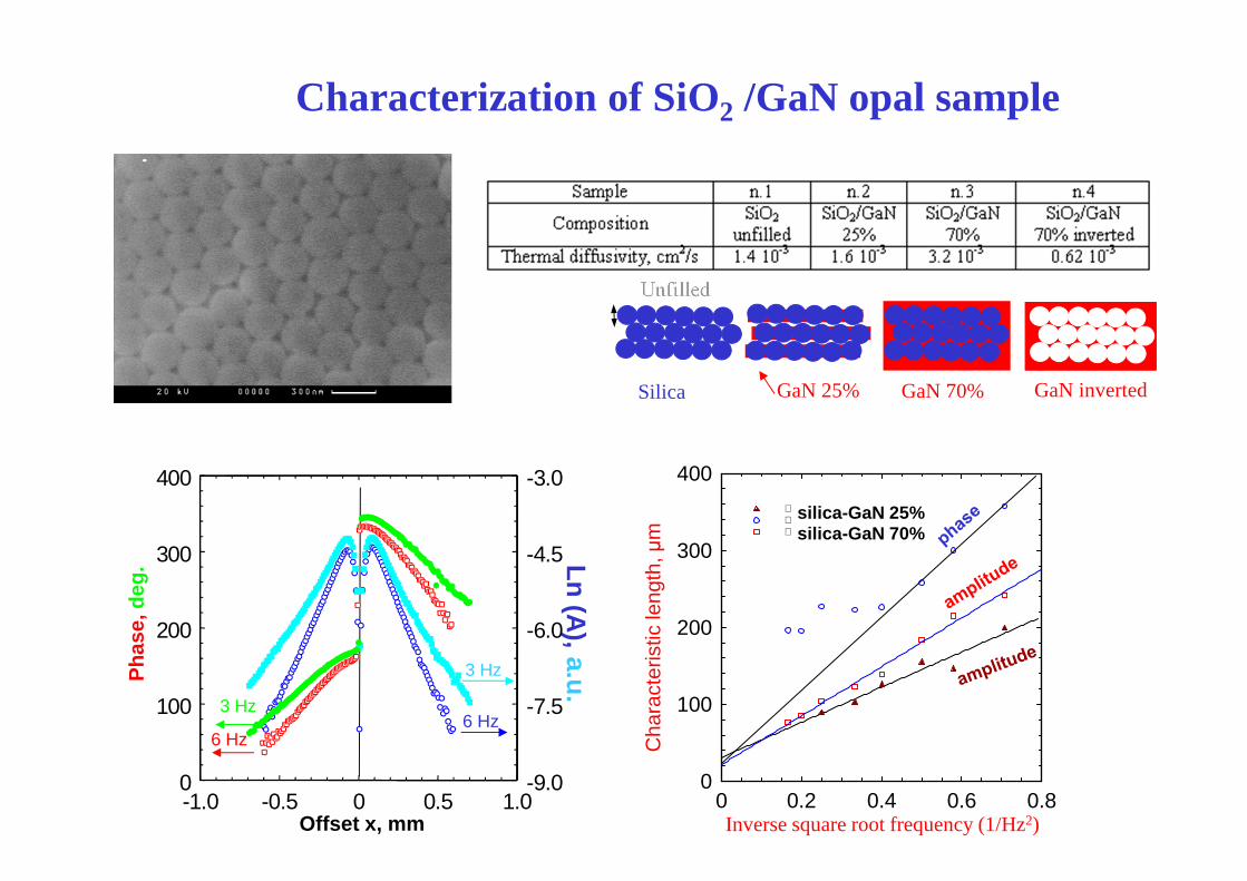
Characterization of SiO2 /GaN opal sampleP
hase
, de
g.
Ln (A), a.u.
3 Hz
6 Hz3 Hz
6 Hz
Offset x, mm
0
100
200
300
400
-1.0 -0.5 0 0.5 1.0-9.0
-7.5
-6.0
-4.5
-3.0
0
100
200
300
400
0 0.2 0.4 0.6 0.8
Cha
ract
eris
tic le
ngth
, µm
Inverse square root frequency (1/Hz2)
silica-GaN 25%silica-GaN 70%
GaN 25% GaN 70% GaN invertedSilica
Unfilled

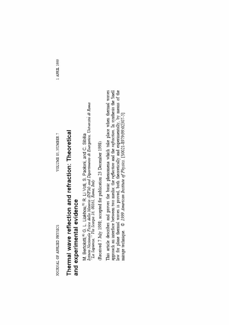
THERMAL WAVE REFLECTION AND REFRACTIONfor plane waves
( ) ( ) ( )[ ] ( ) ( )[ ]
( ) ( ) ( )[ ]
=
+=
θ+θβ−
θ−θβ−θ+θβ−
zxsin2
zxsinzxsin1
222
111111
tAezxT
rAeAezxT
cos
'cos'cos
,~
,~
Medium 2Medium 1
z
x
∂∂=
∂∂
=
z
Tk
z
Tk
TT
22
11
21
~~
~~Temperature must be conserved at z=0
Normal heat flux must be conserved at z=0
( ) ( )
θ=θ
θ=θ
22
11
11
sinD
1sin
D
1
'
( ) ( )( ) ( )
( )( ) ( )2211
11
2211
2211
ee
e2t
ee
eer
θ+θθ=
θ+θθ−θ=
coscos
cos
coscos
coscos
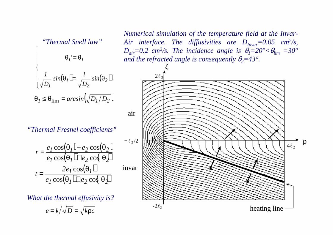
( )211 DDarcsin=θ≤θ lim
ρ
2 2l
ζ
A
air
invar
− l /224 2l
heating line-2 2 l
“Thermal Snell law”
“Thermal Fresnel coefficients”
Numerical simulation of the temperature field at the Invar-Air interface. The diffusivities are DInvar=0.05 cm2/s,Dair=0.2 cm2/s. The incidence angle isθ1=20°<θlim =30°and the refracted angle is consequentlyθ2=43°.
What the thermal effusivity is?
ckDke ρ==
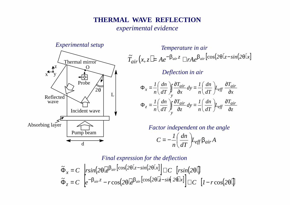
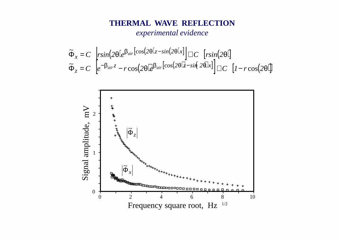
THERMAL WAVE REFLECTIONexperimental evidence
Absorbing layer
Pump beam
Incident wave
Reflected
Thermal mirrorO
wave
x
z
Probe2θ
y
d
L
Experimental setup
( ) ( ) ( )[ ]x2sinz2zair
airair rAeAezxT θ−θββ− += cos,~
∫
∫
∂∂
=∂
∂
=Φ
∂∂
=∂
∂
=Φ
y
aireff
airz
y
aireff
airx
z
TL
dT
dn
n
1dy
z
T
dT
dn
n
1
x
TL
dT
dn
n
1dy
x
T
dT
dn
n
1
ALdT
dn
n
1C aireffβ
−=
( ) ( ) ( )[ ][ ] ( )[ ]( ) ( ) ( )[ ][ ] ( )[ ]θ−≅θ−=Φ
θ≅θ=Φθ−θββ−
θ−θβ
2r1Ce2reC
2rsinCe2rsinC
x2sinz2zz
x2sinz2x
airair
air
coscos~
~
cos
cos
Temperature in air
Deflection in air
Factor independent on the angle
Final expression for the deflection
0 2 4 6 8 10
2
1
0
Frequency square root, Hz1/2
Sign
al a
mpl
i tude
, m
V
THERMAL WAVE REFLECTIONexperimental evidence
( ) ( ) ( )[ ][ ] ( )[ ]( ) ( ) ( )[ ][ ] ( )[ ]θ−≅θ−=Φ
θ≅θ=Φθ−θββ−
θ−θβ
2r1Ce2reC
2rsinCe2rsinC
x2sinz2zz
x2sinz2x
airair
air
coscos~
~
cos
cos
zΦ~
xΦ~
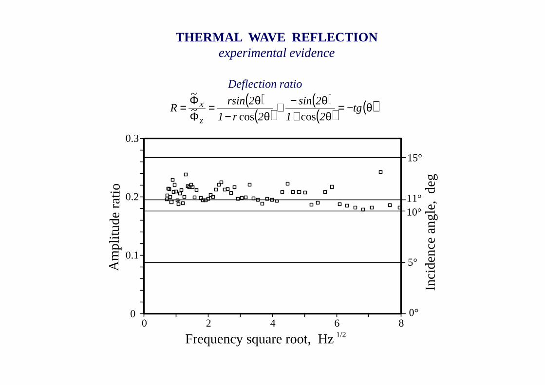
THERMAL WAVE REFLECTIONexperimental evidence
Am
pli t
ude
rati
o
Inci
den
ce a
ng
le,
deg
0 2 4 6 8
0.3
0.2
0.1
0
15°
11°10°
5°
0°
Frequency square root, Hz1/2
( )( )
( )( ) ( )θ−=
θ+θ−≅
θ−θ=
ΦΦ= tg
21
2sin
2r1
2rsinR
z
x
coscos~
~Deflection ratio
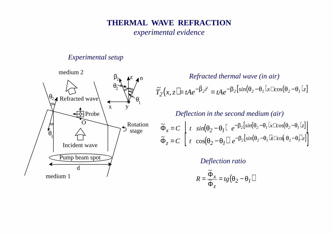
THERMAL WAVE REFRACTIONexperimental evidence
Incident wave
x
z
Probe
θ
O
Pump beam spot
Refracted waveθ
Rotationstage
2
1
medium 2
medium 1
n
θ1
θ2
y
β2
d
Experimental setup
( ) ( ) ( )[ ]zxsinr2
121222 tAetAezxT θ−θ+θ−θβ−β− == cos,~ rr
Refracted thermal wave (in air)
( ) ( ) ( )[ ][ ]( ) ( ) ( )[ ][ ]zxsin
12z
zxsin12x
12122
12122
etC
esintC
θ−θ+θ−θβ−
θ−θ+θ−θβ−
θ−θ=Φ
θ−θ=Φcos
cos
cos~
~
Deflection ratio
( )12z
x tgR θ−θ=ΦΦ= ~
~
Deflection in the second medium (air)
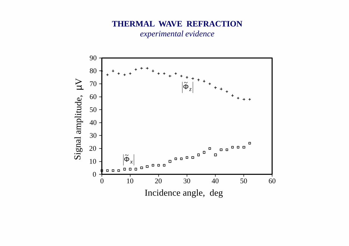
THERMAL WAVE REFRACTIONexperimental evidence
0 20 40 60
90
80
70
60
50
40
30
20
10
010 30 50
Incidence angle, deg
Sig
nal a
mpl
itud
e, µ
VzΦ~
xΦ~
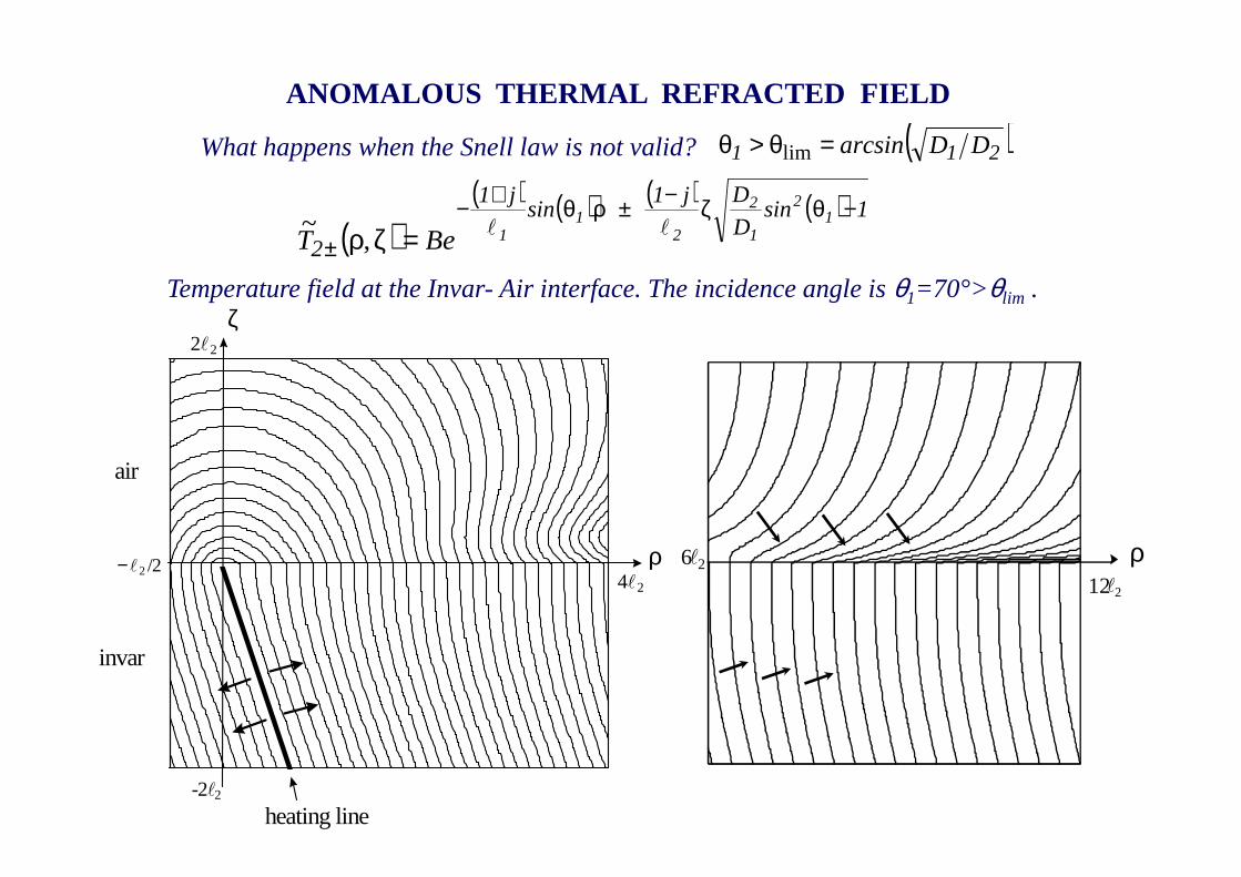
ANOMALOUS THERMAL REFRACTED FIELD
( )211 DDarcsin=θ>θ lim
( )( ) ( ) ( ) ( ) 1sin
D
Dj1sin
j1
2
12
1
2
21
1BeT−θζ−±ρθ+−
± =ζρ ll,~
What happens when the Snell law is not valid?
ρ
2 2l
ζ
air
invar
−l /224 2l
heating line-2 2 l
Temperature field at the Invar- Air interface. The incidence angle isθ1=70°>θlim .
ρl212
6 2l
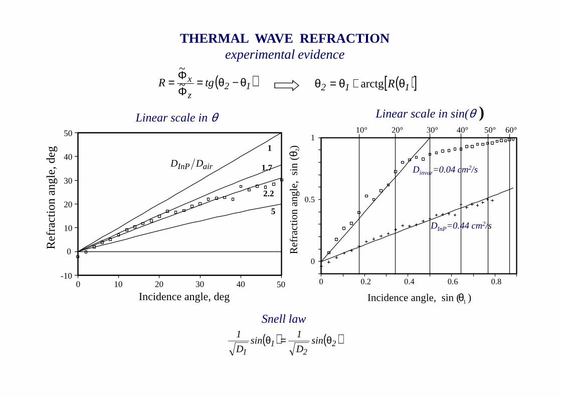
THERMAL WAVE REFRACTIONexperimental evidence
( )[ ]112 R θ+θ=θ arctg( )12z
x tgR θ−θ=ΦΦ= ~
~
0 0.2 0.4 0.6 0.8
1
0.5
0
10°
Incidence angle, sin ( )θ
20° 30° 40° 50° 60°
1R
efra
ctio
n a
ngle
, si
n (θ 2)
Linear scale in θ Linear scale in sin(θ )
airInP DD
0 20 40
50
40
30
20
10
0
-1010 30 50
Incidence angle, deg
1
1.7
2.2
5
Re
fra
ctio
n a
ngle
, de
g
DInP=0.44 cm2/s
Dinvar=0.04 cm2/s
( ) ( )22
11
sinD
1sin
D
1 θ=θ
Snell law
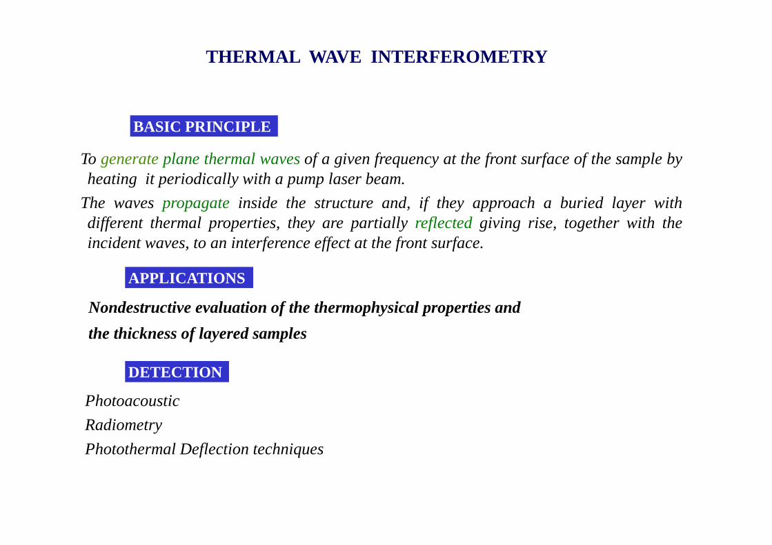
THERMAL WAVE INTERFEROMETRY
BASIC PRINCIPLE
To generateplane thermal wavesof a given frequency at the front surface of the sample byheating it periodically with a pump laser beam.
The wavespropagate inside the structure and, if they approach a buried layer withdifferent thermal properties, they are partiallyreflectedgiving rise, together with theincident waves, to an interference effect at the front surface.
DETECTION
APPLICATIONS
Photoacoustic
Radiometry
Photothermal Deflection techniques
Nondestructive evaluation of the thermophysical properties and
the thickness of layered samples
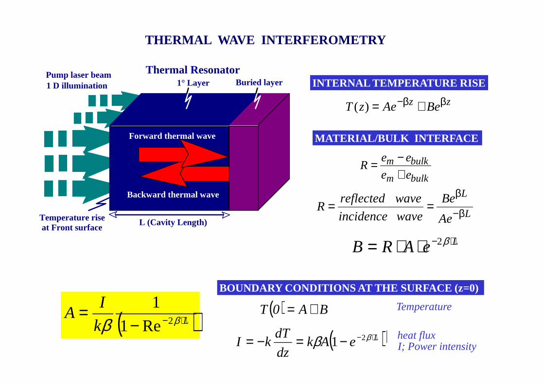
INTERNAL TEMPERATURE RISE
MATERIAL/BULK INTERFACE
BOUNDARY CONDITIONS AT THE SURFACE (z=0)
I; Power intensity
Temperature
heat flux
Thermal Resonator
Forward thermal wave
Backward thermal wave
Pump laser beam1 D illumination
L (Cavity Length)
Buried layer
at Front surfaceTemperature rise
1° Layer
THERMAL WAVE INTERFEROMETRY
zz BeAezT ββ− +=)(
bulkm
bulkm
ee
eeR
+−=
L
L
Ae
Be
waveincidence
wavereflectedR β−
β==
( )( )BAk
dz
dTkI
BA0T
−β=−=
+=
LeARB ⋅−⋅⋅= β2
( )LeAkdz
dTkI ⋅−−=−= ββ 21
( )Lk
IA ⋅−−
= ββ 2Re1
1
-0.9
+0.9
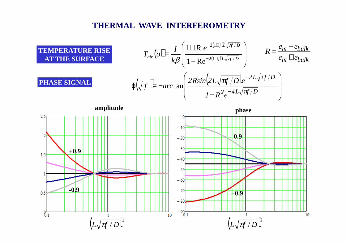
TEMPERATURE RISEAT THE SURFACE
PHASE SIGNAL ( ) ( )
−
π−=ϕ
π−
π−
DfL42
DfL2
eR1
eDfL2Rsin2arcf tan
( )( )
( )
−
+=
+−
+−
DfLj
DfLj
air
eR
k
IoT
/12
/12
Re1
1π
π
β
THERMAL WAVE INTERFEROMETRY
( )2/ DfL π
bulkm
bulkm
ee
eeR
+−=
-0.9
+0.9
phase
-0.9
+0.9
( )2/ DfL π
amplitude
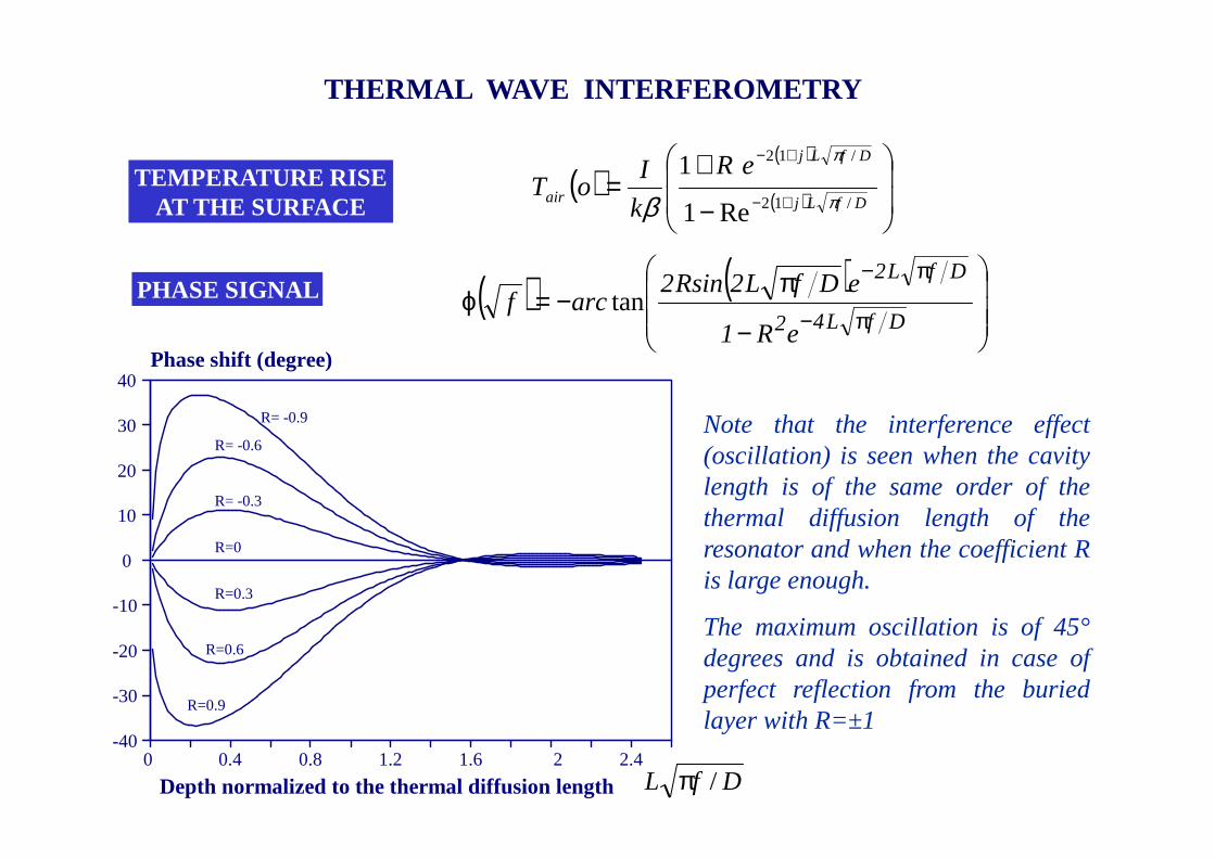
0 0.4 0.8 1.2 1.6 2 2.4
40
30
20
10
0
-10
-20
-30
-40
Depth normalized to the thermal diffusion length
R=0.9
R= -0.9
R=0.6
R= -0.6
R= -0.3
R=0.3
R=0
Phase shift (degree)
TEMPERATURE RISEAT THE SURFACE
PHASE SIGNAL
Note that the interference effect(oscillation) is seen when the cavitylength is of the same order of thethermal diffusion length of theresonator and when the coefficient Ris large enough.
The maximum oscillation is of 45°degrees and is obtained in case ofperfect reflection from the buriedlayer with R=±1
( ) ( )
−
π−=ϕ
π−
π−
DfL42
DfL2
eR1
eDfL2Rsin2arcf tan
( )( )
( )
−
+=
+−
+−
DfLj
DfLj
air
eR
k
IoT
/12
/12
Re1
1π
π
β
DfL /π
THERMAL WAVE INTERFEROMETRY
Opaque coating
Bulk
Air
Vertical Deflection
Illuminated area
Probe beam
Pump beam
z
L
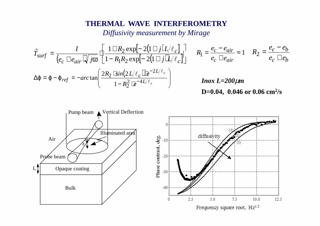
THERMAL WAVE INTERFEROMETRYDiffusivity measurement by Mirage
( )( )[ ]( )[ ]
+−−+−+⋅
ω+=
c
c
aircsurf LjRR
LjR
jee
IT
l
l
12exp1
12exp1ˆ21
2 11 ≈+−=
airc
airc
ee
eeR
bc
bc
ee
eeR
+−=2
Inox L=200µm
D=0.04, 0.046 or 0.06 cm2/s
( )
⋅−⋅⋅−=ϕ−ϕ=ϕ∆ −
−
c
c
L
Lc
refeR
eLsinRarc
l
ll
422
22
1
22tan

Opaque coating
Bulk
Air
Vertical Deflection
Illuminated area
Probe beam
Pump beam
z
L
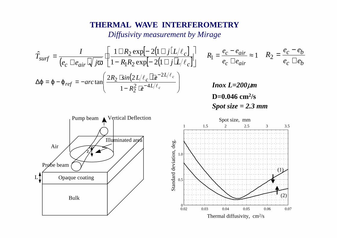
THERMAL WAVE INTERFEROMETRYDiffusivity measurement by Mirage
( )( )[ ]( )[ ]
+−−+−+⋅
ω+=
c
c
aircsurf LjRR
LjR
jee
IT
l
l
12exp1
12exp1ˆ21
2 11 ≈+−=
airc
airc
ee
eeR
bc
bc
ee
eeR
+−=2
Inox L=200µm
D=0.046 cm2/s
( )
⋅−⋅⋅−=ϕ−ϕ=ϕ∆ −
−
c
c
L
Lc
refeR
eLsinRarc
l
ll
422
22
1
22tan
Ph
ase
con
tra
st,
deg.
Spot size
-40
-30
-20
-10
0
0 2.5 5.0 7.5 10.0 12.5
(1)
(2)
(3)
Spot size = 1mm, 2.3mm, 5mm
Opaque coating
Bulk
Air
Vertical Deflection
Illuminated area
Probe beam
Pump beam
z
L
THERMAL WAVE INTERFEROMETRYDiffusivity measurement by Mirage
( )( )[ ]( )[ ]
+−−+−+⋅
ω+=
c
c
aircsurf LjRR
LjR
jee
IT
l
l
12exp1
12exp1ˆ21
2 11 ≈+−=
airc
airc
ee
eeR
bc
bc
ee
eeR
+−=2
Inox L=200µm
D=0.046 cm2/s
( )
⋅−⋅⋅−=ϕ−ϕ=ϕ∆ −
−
c
c
L
Lc
refeR
eLsinRarc
l
ll
422
22
1
22tan
Spot size = 2.3 mm
0
0.5
1.0
0.02 0.03 0.04 0.05 0.06 0.07
Sta
nda
rd d
evia
tion
, deg
.
Thermal diffusivity, cm2/s
Spot size, mm1 1.5 2 2.5 3 3.5
(1)
(2)
Opaque coating
Bulk
Air
Vertical Deflection
Illuminated area
Probe beam
Pump beam
z
L
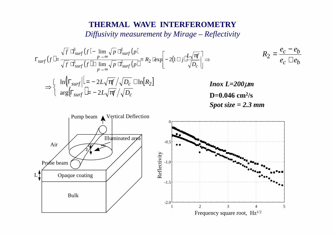
THERMAL WAVE INTERFEROMETRYDiffusivity measurement by Mirage – Reflectivity
bc
bc
ee
eeR
+−=2
Inox L=200µm
D=0.046 cm2/sSpot size = 2.3 mm
-2.0
-1.5
-1.0
-0.5
0
1 2 3 4 5
Frequency square root, Hz1/2
Ref
lect
ivity
( )( ) ( )
( ) ( ) ( ) ⇒
π+−⋅=
⋅+⋅
⋅−⋅=Γ
∞→
∞→
csurfp
surf
surfp
surf
surfD
fLjR
pTpfTf
pTpfTf
f 12expˆlimˆ
ˆlimˆ
2
( ) [ ]( ) csurf
csurf
DfL
RDfL
π−=Γ
+π−=Γ
⇒2arg
ln2ln 2
•Thermal diffusivity and effusivity measurements
•Absorption spectroscopy
•Effusivity and optical absorption depth profiling
•Measurement of the attenuation in optical waveguides
•Evaluation of the thickness of thin layers
•Trace gas analysis
•Evaluation of the photoelastic constants
Main applications
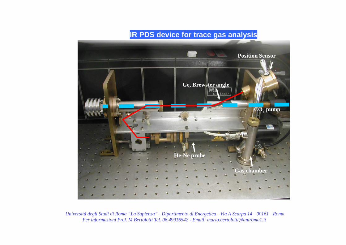
Università degli Studi di Roma “La Sapienza” - Dipartimento di Energetica - Via A Scarpa 14 - 00161 - RomaPer informazioni Prof. M.Bertolotti Tel. 06.49916542 - Email: [email protected]
IR PDS device for trace gas analysis
Ge, Brewster angle
Gas chamber
He-Ne probe
CO2 pump
Position Sensor
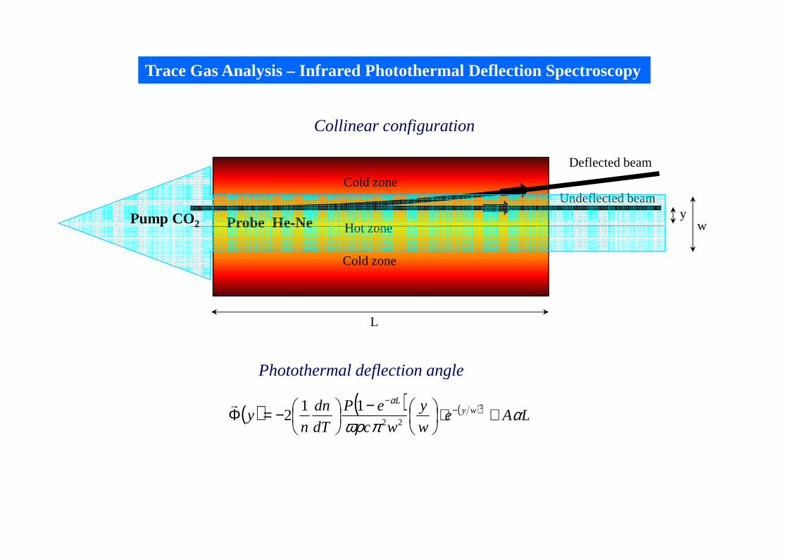
Hot zone
Cold zone
Cold zone
Probe He-Ne
Undeflected beam
Deflected beam
Trace Gas Analysis – Infrared Photothermal Deflection Spectroscopy
( ) ( ) ( ) LAew
y
wc
eP
dT
dn
ny wy
L
απωρ
α
≅⋅
−
−=Φ −−
2
22
112
r
Collinear configuration
Photothermal deflection angle
yPump CO2 w
L
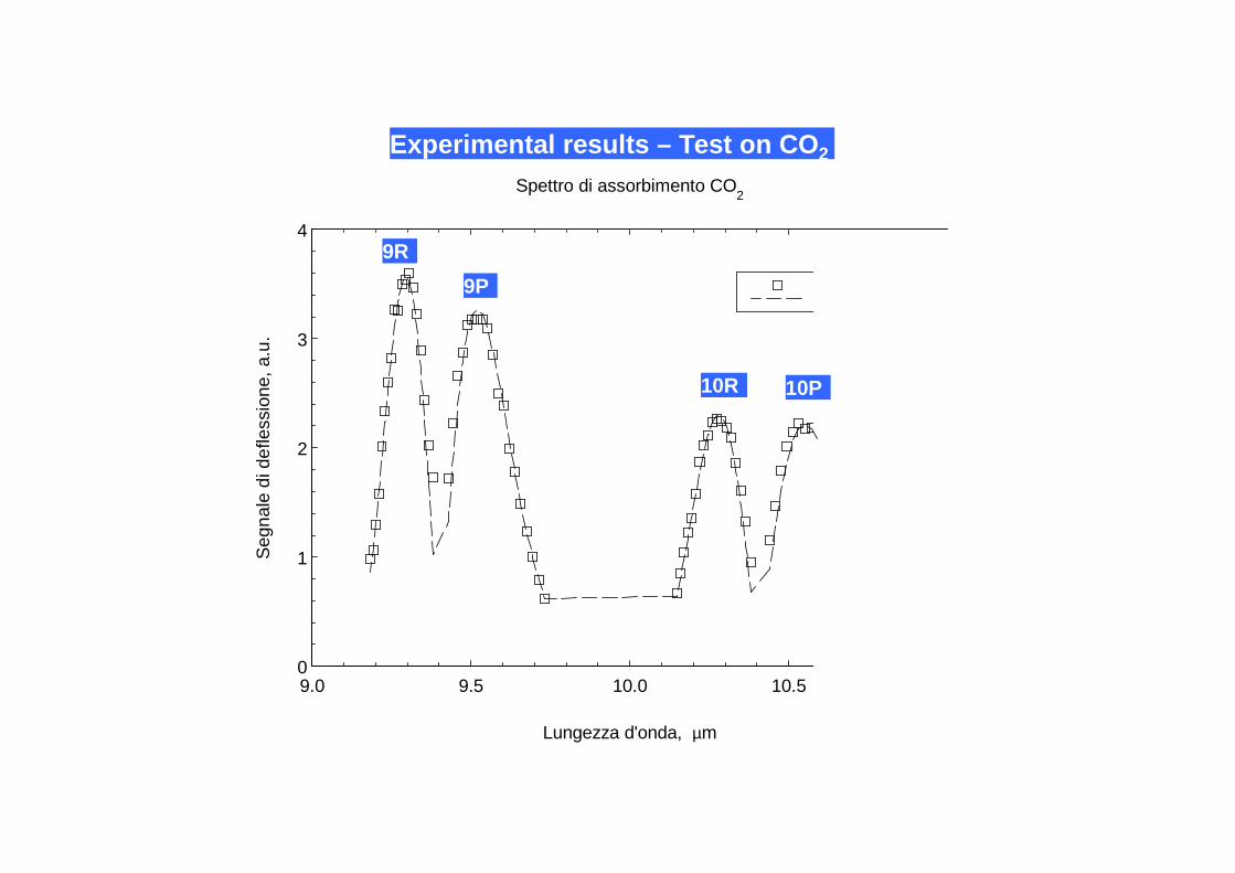
0
1
2
3
4
9.0 9.5 10.0 10.5
Lungezza d'onda, µm
Seg
nale
di d
efle
ssio
ne, a
.u.
Spettro di assorbimento CO2
Experimental results – Test on CO 2
9R
9P
10R 10P

0
0.005
0.010
0.015
0.020
0.025
9.5 10.0
exp.
Lunghezza d'onda, µm
Seg
nale
di d
efle
ssio
ne, V
/W
Spettro di assorbimento di una miscella 50 ppm C2H
4
Experimental Results – Test on C 2H4
10P(14) di C2H4
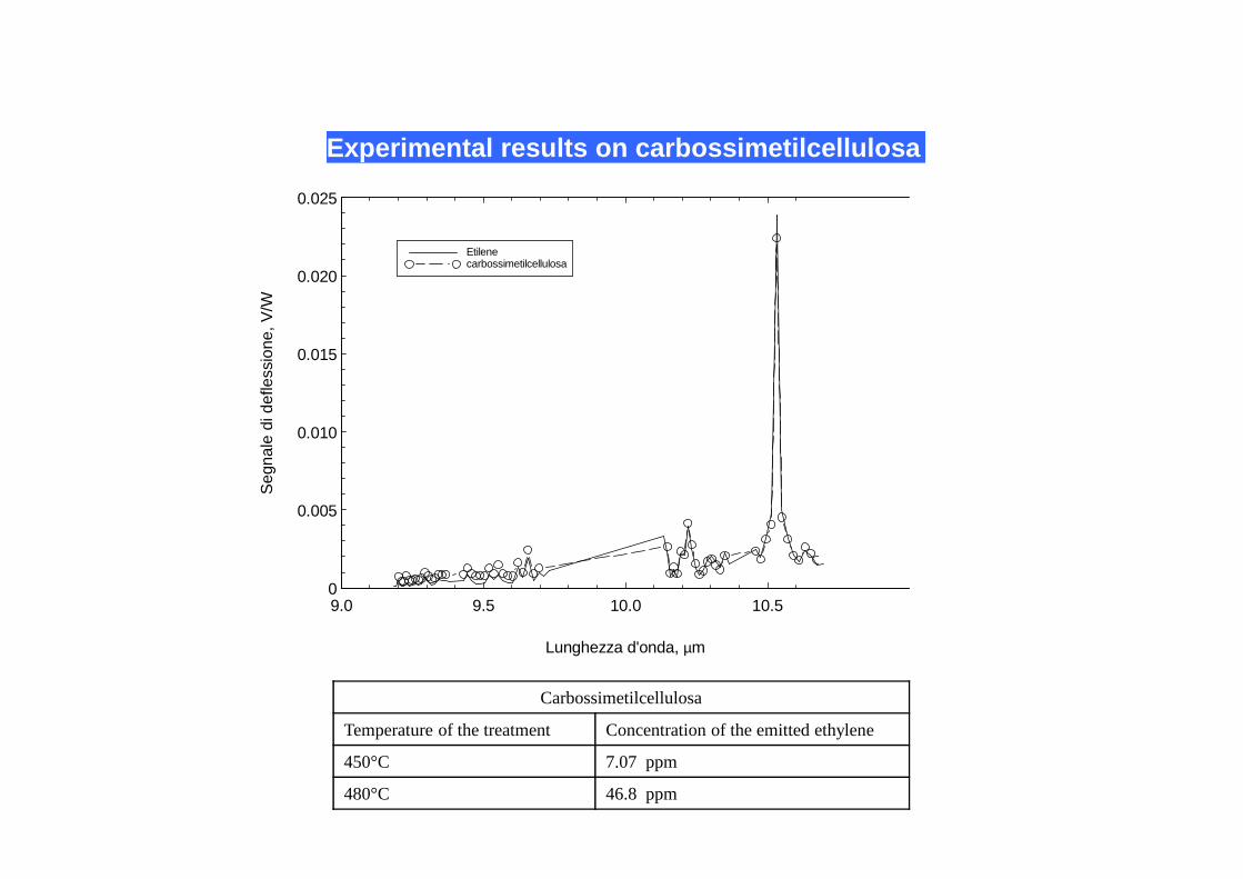
0
0.005
0.010
0.015
0.020
0.025
9.0 9.5 10.0 10.5
Etilenecarbossimetilcellulosa
Lunghezza d'onda, µm
Seg
nale
di d
efle
ssio
ne, V
/W
Experimental results on carbossimetilcellulosa
Carbossimetilcellulosa
Temperature of the treatment Concentration of the emitted ethylene
450°C 7.07 ppm
480°C 46.8 ppm
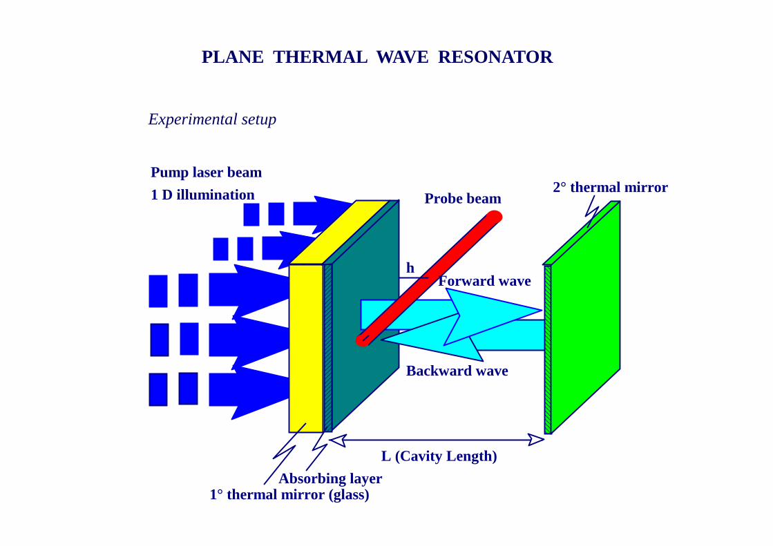
PLANE THERMAL WAVE RESONATOR
Forward wave
Backward wave
Pump laser beam
1 D illumination
L (Cavity Length)
2° thermal mirror
Absorbing layer1° thermal mirror (glass)
Probe beam
h
Experimental setup
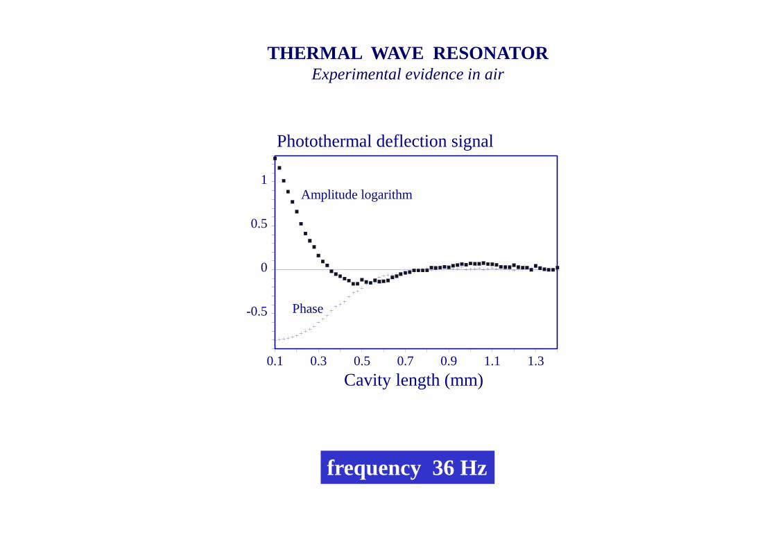
0.1 0.3 0.5 0.7 0.9 1.1 1.3
Cavity length (mm)
1
0.5
0
-0.5
Photothermal deflection signal
Phase
Amplitude logarithm
frequency 36 Hz
THERMAL WAVE RESONATORExperimental evidence in air
• PHOTOTHERMAL TECHNIQUES
• PRINCIPLE OF PHOTOTHERMAL DEFLECTION
•THE HEAT DIFFUSION
• MEASUREMENT OF THERMAL DIFFUSIVITY
• OTHER APPLICATIONS
CONCLUSIONS