Embed Size (px)
Citation preview

Photovoltaic systemconnections and protection
2014 EDITION

Cabur Solar
The Company
UNI EN-ISO 9001 UNI EN-ISO 14001
Founded in 1952, Cabur quickly gained a leading position
among national constructors of terminal blocks for electrical
panels, pursuing a policy which focused particularly on
installers' needs and proposing avant-garde technological
solutions, which in time became generalised applications.
Above all, it was ahead of its time in the qualitative choices for
its products, especially regarding raw materials, as well as
guaranteed functioning, reliability over time and respect for
the environment.
Thanks to all this, in 1985 Cabur obtained Class 1E Qualification
(Equipment for Nuclear Power Generating Stations) and ISO
9001 (Quality) and ISO 14001 (Environment) Certifications, as
well as certified conformity to the ATEX Directive and to the
IEC Ex Scheme for “Ex e” installations on main terminal block
lines.
In 2006 Cabur acquired a new advanced production site, which
stretches over an area of 15,000 m2 in the municipality of
Altare (Savona). The extra surface space and a simultaneous
increase in personnel allowed for rationalising and rendering
even more efficient the production processes, as well as the
logistics and sales activities.
Present production, which is wide-ranging and diversified,
represents the optimal synthesis of Cabur's long experience
as a supplier to the main national energy boards and
companies, together with activities and collaboration abroad.
Today Cabur develops and produces, to its own designs,
a very wide range of products for the electro-technical and
electronics industries, renowned for their reliability even in
extreme working conditions, and created to provide optimal
responses to users' various and complex installation needs.
The offer includes:
a line of terminal blocks for electrical cabinets and panels,
designed to satisfy the fundamental requirements of the
most severe installation conditions.
power supplies and electronic products for electrical
panels, for plant automation, machine automation, and
process control.
a wide range of items for the completion of connections for
civil and industrial installations.
a line of products for the connection and protection of
photovoltaic systems.
a line of products and solutions for industrial marking.
For documentation on our products, visit our site www.cabur.eu;
you can request all our publications and also receive invitations
to trade fairs where Cabur is present, and a periodic e-mail
newsletter.

solar
Index
Cabur, connected and safe ... in all circumstances
Cabur Solar. A range of solutions for PV system connection and protection
Photovoltaic systems. Mounting systems
Photovoltaic systems. Connections and wiring
Photovoltaic systems. String boxes, control units and their components
Photovoltaic systems. Terminal blocks
Code index
03
04
05
25
51
90
103

Cabur Solar Page 3
CaburConnected and safe ... in all circumstances
The choice of connection systems is one of the critical factors
on which the effective performance of the PV system, its
efficiency over time and its useful lifetime depend.
To maximise and guarantee efficiency over time, Cabur offers
a range of solutions which guarantee connections which
conform with the highest standards on the market.
From the Cabur offer, the installer can choose the right
connectors for the technical features of the system and the
specifications of the modules and inverters available on the
market or already installed.
It is very simple to choose the best solution:
for combination with the most common inverters/junction
boxes, Cabur offers the Cabur Solar line, which includes
connectors for PIN diameters (3 or 4 mm) identified by the
"Line 3" or "Line 4" name;
for connection with Tyco Electronics inverters/junction
boxes, Cabur offers the Solarlok® connectors, for which it is
the authorised dealer.
Both product families are excellent for joining photovoltaic
wires and include a complete connection set, with wires, tools
and accessories, as well as an ideal First Installation Kit.
To guarantee safety, duration over time and maximum
efficiency of the system, Cabur also offers selected products
and components, such as:
mounting systems for photovoltaic panels;
a variety of string boxes conforming to safety standards;
solar combiner boxes with integrated electronics for
monitoring and measure power/energy;
control units for civil systems;
surge protection devices;
screw-clamp terminal blocks;
distribution terminal boards;
control rail assemblies;
diodes for strings;
switches and disconnectors;
fuse holders;
boxes and other components for distribution panels;
warning labels.

Page 4
solar
Cabur SolarA range of solutions for PV system connection and protection
DCAC
DCAC
String boxes to protect and
control line and relative
components (see pages
53 to 55)
Cabur Line 3,4 and Tyco
mobile photovoltaic
connectors for joining
electric lines composed
of photovoltaic wires
(see pages 26 to 42)
Mounting systems for
photovoltaic panels
(see pages 6 to 24)
Wires for photovoltaic
systems for
wiring the system
(see pages 48,49,50)
aic
)

Cabur Solar
Innovative patented system for positioning and mounting photovoltaic panels equipped with metallic frames on any surface and at any angle.
Photovoltaic systemsMounting systems
FROM PAGE 6 TO PAGE 24
Cabur Solar Fix. A solution for every type of roof
Cabur Solar Fix. Support bracket for attaching photovoltaic panels to corrugated metal roofs
Many advantages and a savings of 30% by using the brackets for corrugated metal roofs
Recommendations on using the brackets correctly
Support brackets. How to order
Components for the brackets
Accessories for the brackets
Supports for anchoring on curved tiles/flat tiles and on corrugated sheets
Tilter. Supports for flat roofs
Plates
Spacers
Plastic rail. The only rail in plastic for photovoltaic systems
Recommendations for correct use
Intermediate and final anchoring systems
The components
Cabur Solar Fix. Accessories for the supports
06
07
08
10
13
14
15
16
17
18
19
20
21
22
23
24

Page 6
solar
Cabur Solar FixA solution for every type of roof
TYPES OF SURFACES
TYPE OF ATTACHMENT OF THE PHOTOVOLTAIC PANEL
Recommended system
of supportEssential elements of the system Page Optional accessories kit Page
CORRUGATED METAL ROOFS
Brackets 13 Stainless steel anti-theft tear-off nut 15
Anchoring plates 14 Rubber insulating sheets 15
Fastening screws 14 Self-drilling and self-threading screws 15
Plastic profile 20 Stainless steel anti-theft tear-off nut 24
Sliding plastic cursor 23 Rubber insulating sheets 24
Fastening angle bar 23 Self-drilling and self-threading screws 24
Anchoring plates 23
Fastening screws 23
CURVED TILE ROOF
ISFIXSP2 type supports 16 Clips for fastening wires to the rails 24
Intermediate plates and end sections 18 Union joint 24
Profiles in aluminium and zinc-plated steel 17 Stainless steel anti-theft tear-off nut 24
ISFIXSP1 type supports 16 Clips for fastening wires to the rails 24
Intermediate plates and end sections 18 Union joint 24
Profiles in aluminium and zinc-plated steel 17
Stainless steel anti-theft tear-off nut24
FLAT CEMENT ROOFS
Brackets 13 Stainless steel anti-theft tear-off nut 15
Anchoring plates 14 Rubber insulating sheets 15
Fastening screws 14 Self-drilling and self-threading screws 15
Plastic profile 20 Stainless steel anti-theft tear-off nut 24
Sliding plastic cursor 23 Rubber insulating sheets 24
Fastening angle bar 23 Self-drilling and self-threading screws 24
Anchoring plates 23
Fastening screws 24
Tilter 17
Profiles in aluminium and zinc-plated steel 17
Intermediate plates and end sections 18
CORRUGATED METAL ROOFS
ISFIXSP1 type supports 16 Clips for fastening wires to the rails 24
Intermediate plates and end sections 18 Union joint 24
Profiles in aluminium and zinc-plated steel 17
Stainless steel anti-theft tear-off nut24
Type D brackets 13 Stainless steel anti-theft tear-off nut 24
ISFIXPPL type plastic profiles 20 Rubber insulating sheets 24
Sliding plastic cursor 23 Self-drilling and self-threading screws 24
Fastening angle bar 23
Anchoring plates 23
Fastening screws 23
Inte
Pr
Inte
Pr

Cabur Solar Page 7
Cabur Solar FixSupport bracket for attaching photovoltaic panels to corrugated metal roofs
Innovative patented system for positioning and fastening
photovoltaic panels equipped with metallic frames on
corrugated metal sheets and at any angle.
The system is based on the use of brackets, complete with
relative accessories (screws, washers and plates).
To satisfy various installation needs, models with different
profiles are available (see drawings on page 13), each of which
is available with stainless steel or plastic plates.
Panel anchorage requires a certain number of brackets with
intermediate plates (to be inserted between adjacent panels)
and brackets with end plates (to be inserted at the edges of
the string), depending on the number of panels to be installed.
The difference between the intermediate and end plates is the
shape: the end plates are in fact folded into an L to compensate
for the lack of an adjacent panel.
To calculate the number of brackets, consult the specific
paragraph (see page 13).
+ EFFICIENCY- COSTS
End bracket
with plastic plate
End bracket
with plastic plate
Intermediate bracket
with plastic plate
Intermediate bracket
with plastic plate
Technical features
Material: Durethan BKV 30H
Estimated minimum duration: 20 years with exposure
to the UVA component of sunlight
Mechanical properties verified by the European
Quality Institute in Fabriano (AN)
Resistance to rain, wind, and UV rays verified by the
European Quality Institute in Fabriano
Maximum recommended tightening torque: 10 Nm
Conservation of the mechanical
properties
Regarding the plastic's conservation of its mechanical
properties despite exposure to solar radiation -- UVA
rays -- special tests were carried out by the European
Quality Institute in Fabriano (AN), under the inspection
control of TÜV Rheinland Italia.
The tests show that the mechanical resistance of the
Cabur Solar Fix brackets remains practically constant
over time, even after prolonged exposure to UVA rays.
PATENTS: The Cabur Solar Fix Bracket is protected by an international patent.

Page 8
solar
Cabur Solar FixMany advantages and a saving of 30% with the use of the brackets for corrugated metal sheets
The angle of tilt
Orientation 0° 30° 60° 90°
East 93% 90% 78% 55%
South-East 93% 96% 88% 66%
South 93% 100% 91% 68%
South-West 93% 96% 88% 66%
West 93% 90% 78% 55%
1. Take advantage of surfaces not otherwise used
Although it is true that a surface of PV panels that do not fact
in the optimum direction has a lower yield, it is also true that it
will, in any case, yield a quantity of energy in additional to that
produced by the other strings of the system. The construction
of a photovoltaic system involves the installation of the panels
in a manner which satisfies the basic requisites such as
SOUTH facing and an optimum TILT angle, as well as other
factors to minimise the effect of shade and dirt which could
occur.
The table below shows, for example, that a panel facing
west sloping 0° (to the horizontal) yields almost as much
as the classic south-facing panel at a 30° tilt. Thanks to its
versatility, the Cabur Solar Fix bracket means that panels
can be attached at various angles, meaning that all available
surfaces can be used.
2. Maximum yield
The special shape of the bracket creates a hollow ventilation
space, without the hindrance of secondary structures, of
more than 4 cm between the photovoltaic module and the
surface beneath. This means that the system is less subject
to overheating, giving a greater yield.
3. Universal and versatile
Thanks to the two corrugation profiles, it is possible to cover
practically every type of corrugated panel measurement; the
holes in the wings at the base of the bracket also allow for use
on wood or cement roofs.
The bracket can be used to anchor the photovoltaic panel
strings on normal tiles roofs of civil buildings, as well as on
metallic roofs typical of industrial buildings.
4. Simple and lightweight
Assembly is fast and simple: with a few steps, the bracket is
ready to anchor the photovoltaic modules.
The support is light due to the material used (especially if
compared to the traditional aluminium anchorage profiles).
The bracket also has exceptional mechanical resistance
which, together with its light weight, makes the installer's
work much easier when laying the panels. It will no longer
be necessary to lift up to the roof, sometimes working in
extremely uncomfortable positions, large quantities of
aluminium profiles, but above all it will no longer be necessary
to cut and shape the metallic frames to adapt them to both the
The Great Innovation
in anchorage systems
1. With maximum exploitation of the surface,
positioning the panels at different slopes, following the
shape of the surface on which they rest.
2. Obtain the maximum output from the system,
reducing heating of the panels to the minimum.
3. Universal and versatile, suitable for almost all
sandwich panels on the market, on corrugated metal
roofs, tiled, or wooden or cement roofs.
4. Allows simple and fast installation, with lightweight,
easy to handle components.
5. For aesthetically and architecturally elegant and
modern solutions.
6. Perfect for attaching panels to corrugated metal
roofs, when replacing Eternit roofs, maximising the
associated incentives.
7. Made of eco-friendly materials, chosen to ensure
maximum duration of system components.
8. Costing about 30% less, for the same power installed,
than traditional systems using aluminium profiles.

Cabur Solar Page 9
panels and the shape of the roofing. In addition, with the same
surface area and using the same type of photovoltaic panels,
with Cabur Solar Fix brackets more panels can be installed,
placed much closer together and with only minimal space left
between them.
5. Obtain modern solutions, aesthetically and architecturally
elegant.
The system based on Cabur Solar Fix brackets allows
architects to develop aesthetically elegant solutions and to
give them a personal character, altering the geometry of
the buildings according to photovoltaic technology, in an
architectural combination of harmoniously pleasant forms
and at the same time with a modern appearance, which can
make a mark over time on the architectural style.
6. Possibility to exchange old and dangerous Eternit roofs
still found on thousands of Italian buildings with an elegant
and money-saving replacement1
Old roofs in Eternit are normally replaced by corrugated
metallic roofs. Cement slabs containing asbestos on
industrial roofs are generally replaced by steel-insulation-
steel sandwich panels.
The Cabur Solar Fix device is ideal for anchoring photovoltaic
modules to this type of roof, thanks to its design which adapts
perfectly to the sizes of the standard corrugations. In the
case of removal of asbestos roofs, the photovoltaic energy
production conversion incentive increases by 10% (please
refer to the GSE regulations in effect for more information)1.
7. Quality of the material
The bracket is made of Durethan BKV 30H by Bayer/Lanxess,
already used in the automotive sectors and for other
photovoltaic applications. Especially on metallic roofs, this
material insulates the roof from the photovoltaic module,
avoiding the formation of galvanic and creeping currents. This
means that there will be no anodic oxidation of the metals in
contact with each other, nor rust problems in areas near the
shore where the atmosphere is warm, damp and salty.
Furthermore, the material is not subject to rot or to freezing,
and it is resistant at both high and low temperatures.
Less energy is needed for its production than for metal
brackets, which means lower CO2 emissions into the
atmosphere. The brackets are also made with 20% recycled
material.
8. Cost
Since about 10 brackets are needed for every KW of
photovoltaic power installed (including intermediate and
end brackets), compared to traditional anchorage systems
with aluminium profiles and with the same amount of
photovoltaic power installed on the roof, using Cabur Solar
Fix reduces costs by about 30%. Cabur Solar Fix furthermore
satisfies the condition for applying the rebate (Art. 14 letter
d) Italian Ministerial Decree 5 May 2011), which concerns the
components other than the labour, referable to a product
from within the European Union.
Cabur Solar FixMany advantages and a saving of 30% with the use of the brackets for corrugated metal sheets
1 The data and information provided here refers to the regulations in effect at the time this document was prepared. For up to date
information, please refer to the official GSE documentation. (GSE: Gestore dei Servizi Energetici - Italian Energy Services Manager).

Page 10
solar
Cabur Solar FixRecommendations for correct use of the brackets
EXAMPLE OF ASSEMBLY ON METAL SANDWICH PANELS WITH
NARROW CORRUGATION
EXAMPLE OF USE ON METAL SANDWICH PANEL
A - anchorage with screws on steel sandwich panels can be carried out with the upper vertical holes (A) and/or the prints on the sloping walls of the bracket (B)
Bracket on narrow corrugation
Fixing of photovoltaic panels with metallic frame
The bracket allows for anchorage on:
sandwich panels (the typical roofs of industrial sheds);
smooth sloping roofs (the typical roofs of residential
dwellings with rounded tiles) and on cement mix surfaces or
wooden boards;
corrugated metal sheets.
Approximate indications are given below for the most common
cases.
Installation on corrugated metal roofing
Most sandwich panels have two different corrugation sizes:
narrow and wide. The bracket can be positioned according to
the profile of the type of panel (see drawing below left).
nut
washer
final anchorage
bolt
Solar Fix
rubber membrane
PH
OT
OV
OLTA
IC
MO
DU
LE
VE
NT
ILA
TIO
N
CA
VIT
YS
AN
DW
ICH
PA
NE
L
fixing screwswith washer*
photovoltaic module
metal sandwich panel
Solar Fix installed with final anchorage

Cabur Solar Page 11
Cabur Solar FixRecommendations for correct use
The brackets are anchored to the corrugations of the panels
with perforating and self-threading screws at reciprocal
distances depending on the size of the single photovoltaic
panel.
1 2
The presence of the corrugations allows for fast and simple
alignment of the brackets.
3
The various panels forming the photovoltaic strings are
positioned and the string is "closed" with the end brackets
on the perimeter. The intermediate wiring of each string, like
its connection to the rest of the system, is carried out and
assured with CABUR mobile photovoltaic connectors.
4
The system is finished and ready to be connected to the
inverter.
Installation on metallic roof sandwich panels
The following sequence of images shows the steps for the
creation of photovoltaic systems on metallic roofs of industrial
sheds.
Page 12
solar
Cabur Solar FixRecommendations for correct use
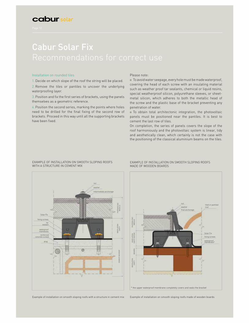
Example of installation on smooth sloping roofs with a structure in cement mix
EXAMPLE OF INSTALLATION ON SMOOTH SLOPING ROOFS
WITH A STRUCTURE IN CEMENT MIXEXAMPLE OF INSTALLATION ON SMOOTH SLOPING ROOFS
MADE OF WOODEN BOARDS
Example of installation on smooth sloping roofs made of wooden boards
PH
OT
OV
OLTA
IC
MO
DU
LE
Installation on rounded tiles
1. Decide on which slope of the roof the string will be placed.
2. Remove the tiles or pantiles to uncover the underlying
waterproofing layer.
3. Position and fix the first series of brackets, using the panels
themselves as a geometric reference.
4. Position the second series, marking the points where holes
need to be drilled for the final fixing of the second row of
brackets. Proceed in this way until all the supporting brackets
have been fixed.
Please note:
To avoid water seepage, every hole must be made waterproof,
covering the head of each screw with an insulating material
such as weather proof tar sealants, chemical or liquid resins,
special weatherproof silicon, polyurethane sleeves, or sheet-
metal silicon, which adheres to both the metallic head of
the screw and the plastic base of the bracket preventing any
penetration of water.
To obtain total architectonic integration, the photovoltaic
panels must be positioned near the pantiles. It is best to
cement the last row of tiles.
On completion, the series of panels covers the slope of the
roof harmoniously and the photovoltaic system is linear, tidy
and aesthetically clean, which certainly is not the case with
the positioning of the classical aluminium beams on the tiles.
Solar Fix
fixing screws
tar sealant
waterproof membrane
reinforced concrete screed
plug
nut
washer
intermediate anchorage
PH
OT
OV
OLTA
IC
MO
DU
LE
VE
NT
ILA
TIO
N
CA
VIT
Y S
YS
TE
MB
OA
RD
S
VE
NT
ILA
TIO
N
CA
VIT
Y
waterproof membrane*
fixing screws
Solar Fix
final anchorage
washer
nuttiled or pantiled
roof
* the upper waterproof membrane completely covers and seals the bracket
CE
ME
NT
MIX
RO
OF
VE
NT
ILA
TIO
N
CA
VIT
Y

Cabur Solar Page 13
BR
AC
KE
T T
YPE
A Code ISFIX00
Bracket profile A and 110x130 mm rubber sheet (the package does not contain any other accessories)
20 pieces per pack
Code ISFIX00B
Bracket profile B and 110x130 mm rubber sheet (the package does not contain any other accessories)
20 pieces per packBR
AC
KE
T T
YPE
B
Code ISFIX00C
Bracket profile C and 110x130 mm rubber sheet (the package does not contain any other accessories)
20 pieces per packBR
AC
KE
T T
YPE
C
Code ISFIX00D
Bracket profile D and silicon rubber washers (the package does not contain any other accessories)
20 pieces per packTYP
E D
BR
AC
KE
T
119 110
27.7 27.83
39.2
5731.5 31.5
55
39.2
34 42 34
140 119
35 29
40
8527.5 27.5
68
46
30 59 30
130
50 11.5
32
15
10
119
25
60
34
29.5 29.5
100
21
47
34
30 40 30
ATTENTION: to guarantee the maximum adaptability of the
Cabur Solar Fix system to the specific requirements of every
installation, starting in 2012 the brackets are distributed
without plates and screws, which must be selected based
on the height and arrangement of the panels. Consequently,
instead of the old items, the individual components (brackets,
screws and plates) must be ordered.
How to order: every package includes the bracket and its
rubber sheet. It does not include the plates, the screws and
the accessory components, which must be ordered separately.
Cabur Solar FixSupport brackets. How to order
To calculate the quantity, take into consideration:
the number of panels (P) in every row
the number of rows of panels (N)
the number of strings (Sr)
Calculation of the number of brackets (S):
for 1 row of panels: S = 2P + 2
if the string has N rows: S = N(2P + 2)
if Sr is the number of strings of the system:
S = SrN(2P + 2)
NOTE: the above formulas give the exact number of brackets required
for each square or rectangular string with a continuous structure,
i.e. with no empty spaces between them. For strings with other or
irregular shapes, the formulae give a purely indicative value.
NOTE: The drawings are purely indicative. The proportions may no
correspond to the actual ones. Therefore please refer to the quotes
given above for the real measurements.
Calculation of the number of brackets

Page 14
solar
The anchoring of the photovoltaic panels onto corrugated
metal requires the use of the brackets (see page 13) and
the necessary components, to be selected based on the
characteristics of the installation.
Select the number of plates by type (intermediate and end)
based on the number and arrangement of the panels and
strings
Select the model of the plates based on the material
chosen (plastic or stainless steel)
Select the type of end plates and screws based on the
thickness of the panels.
Cabur Solar FixThe components for the brackets
Panel Thickness Intermediate Plate End Plate
in plastic in stainless steel in plastic in stainless steel
31 mm
ISFIXSPPLI ISFIXSPAZI
ISFIXSPPL31T ISFIXSPAZ31T
35 mm ISFIXSPPL35T ISFIXSPAZ35T
38 mm ISFIXSPPL38T ISFIXSPAZ38T
40 mm ISFIXSPPL40T ISFIXSPAZ40T
42 mm ISFIXSPPL42T ISFIXSPAZ42T
46 mm ISFIXSPPL46T ISFIXSPAZ46T
50 mm ISFIXSPPL50T ISFIXSPAZ50T
Code ISFIXVTAZ60 ISFIXVTAZ65 ISFIXVTAZ70 ISFIXVTAZ75
DescriptionM6 x 60 screw including
nut and washer
M6 x 65 screw including
nut and washer
M6 x 70 screw including
nut and washer
M6 x 75 screw including
nut and washer
Panel thickness (mm) 31 35-38 40-42 46-50
Quantity per pack 100 100 100 100
ANCHORING PLATES (in packs of 20 pieces)
FIXING SCREWS

Cabur Solar Page 15
Code ISFIXDAF ISFIXVLO ISFIXG
Description Stainless steel anti-theft tear-off nut. M6.
Stainless steel self-piercing and self-threading screw for attachment to all Cabur Solar Fix brackets for corrugated sheet metal roofs. L=25mm - Ø=1.8mm
Insulating rubber sheets, 110x130 mm
Quantity per pack 50 pieces per pack 500 pieces per pack 10 pieces per pack
Code ISFIXCLP ISFIXDUO
Description Clips for fastening wires to the profiles Union joint for profiles
Quantity per pack 100 pieces per pack 5 pieces per pack
ISFIXDUOISFIXCLP
Cabur Solar FixBracket accessories

Page 16
solar
Code ID number Description Pcs x pack
ISFIXSP1 ISFIXSP1 Support for anchoring on corrugated metal sheets for 40x40 mm profiles 5
ISFIXSP2 ISFIXSP2 Support for anchoring on curved tiles for 40x40 mm profiles 5
SupportsSupports for anchoring on curved/flat tiles and on corrugated sheets
Supports for anchoring on curved tiles (code ISFIXSP2) allow photovoltaic modules of any size to be fastened to curved tiles.
The bracket, fastened to the roof, is composed of a galvanised steel part and a plastic part. The union of these two materials is
the real peculiarity of this unique product.
NOTE: both products can be combined with the plates for ISFIXSP type panels...., as per page 18.
Materials: 30% fibreglass with nylon 6 and thermoplastic rubber. Both materials are tested for 20 years of use and wear, as
required in photovoltaic installations.
Supports for anchoring on corrugated sheets (code ISFIXSP1) allow photovoltaic modules of any size to be fastened to
corrugated metal sheets supported by wooden ties. The corrugated sheet is fastened to the ties with a self-threading screw. A
thermoplastic rubber seal guarantees that it is watertight and prevents water from infiltrating.
ISFIXSP2
ISFIXSP1

Cabur Solar Page 17
TilterSupports for flat roofs (code ISFIXINC)
The support for flat roofs is composed of 40mm x 40mm
profiles and a plastic support with adjustable height.
It is designed to ensure the best output from the photovoltaic
panels should it be necessary to install a support structure on
a flat roof.
Its characteristic is that of allowing the modules to be tilted up
to a 10° angle of tilt relative to the support surface.
Intermediate and end plates (type ISFIX xx l and ISFIX xx T) (see page 18)Aluminium profile
(type ISFIXPAL) or in zinc-plated steel (type ISFIXPAZ).
Tilter (type ISFIXINC)
± 10°
12.5 - 19.5 cm
40 mm
40 mm
Code ID number Description Pcs x pack
ISFIXINC ISFIXINC Tilter 5
ISFIXCLP* ISFIXCLP* Fastening clips for wires 100
ISFIXDUO ISFIXDUO Union joint 5
ISFIXPAZ ISFIXPAZ 40x40mm zinc-plated steel profile 5 bars of 3 m / each
ISFIXPAL ISFIXPAL 40x40mm aluminium profile 5 bars of 3 m / each
* See page 14.

Page 18
solar
Intermediate plate End plate
CODE ISFIXSPxxI CODE ISFIXSPxxT
Panel Thickness Intermediate Plate End Plate Pcs x pack
31 mm ISFIXSP31I ISFIXSP31T 5
35 mm ISFIXSP35I ISFIXSP35T 5
38 mm ISFIXSP38I ISFIXSP38T 5
40 mm ISFIXSP40I ISFIXSP40T 5
42 mm ISFIXSP42I ISFIXSP42T 5
46 mm ISFIXSP46I ISFIXSP46T 5
50 mm ISFIXSP50I ISFIXSP50T 5
PLATES FOR PHOTOVOLTAIC PANELS
(can be combined with ISFIXSP1, ISFIXSP2 and ISFIXINC)
PlatesPlates for photovoltaic panels
Intermediate plates and end plates: this system allows
galvanised metal plates to be supported and the photovoltaic
modules fastened with plastic anchorage supports. These
plates are made of 30% nylon 6 reinforced fibreglass and are
divided into two groups: end plates and intermediate plates.
The first are used in external end modules and must be of
the same height. The others are used in the intermediate
modules and are a standard height.
Clips are also available for anchoring and passing the
photovoltaic wires (code ISFIXCLP - see page15).
ISFIXSPxxT

Cabur Solar Page 19
photovoltaic module
100x40x4 aluminium plate
ø6,3 self-piercing screw
Ω 100x60x30x2,5
100x40x4 aluminium plate
ø6,3 self-piercing screw
INSTRUCTIONS FOR USE
5.5 6.5
35.2 35.3
5.5
13.514.8
TECHNICAL DATA
Spacers(code ISFIXDST)
It is strongly recommended for applications in which the
photovoltaic modules come into contact with a support
structure, normally in a material other than that of the
modules which are in anodised aluminium.
In fact, in certain environmental conditions, such as salty fog,
the different types of metal in contact oxidise over time which
deteriorates the components and downgrades the mechanical
and functional characteristics. The spacer in an insulating
material resolves the problem by separating the frame of the
modules from the supporting structure.
Distributed in packs of 100 pieces

Page 20
solar
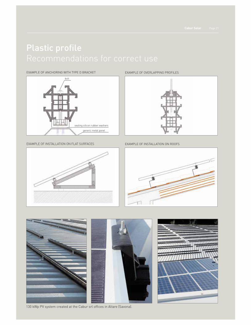
Plastic profile The only rail in plastic for photovoltaic systems
Use
Cut the bars to size and drill them easily and at the
worksite
Use several screw systems for the anchoring (Figure 1)
Use the same bar even for spans without bends
or angles beyond the limit of one bar by joining two
bars
Create simple framed structures.
Advantages of the system
Electrically insulated (protects from galvanic currents,
anodic oxidations, etc.)
Free of oxidation and corrosion phenomena also
where salty fogs are present
Light.
This new anchoring system for photovoltaic panels is
composed of extruded plastic Durethan BKV 325 bars 3.2
metres long attached to the roof by L-shaped stainless steel
plates (see page 23).
The photovoltaic panel rests on the pair of bars and is fastened
there with the items listed on page 23 and the locking KIT,
selected based on the thickness of the panel.
Code ISFIXPPL
Description: Profile in Durethan BKV 325 plastic material
Quantity per pack: 5 bars of 3.20 m/each
Components and accessories: see pages 23-24
Cabur Solar Page 21
bolt
sealing silicon rubber washers
generic metal panel
Plastic profileRecommendations for correct use
EXAMPLE OF INSTALLATION ON FLAT SURFACES
EXAMPLE OF ANCHORING WITH TYPE D BRACKET
EXAMPLE OF INSTALLATION ON ROOFS
EXAMPLE OF OVERLAPPING PROFILES
130 kWp PV system created at the Cabur srl offices in Altare (Savona).
Page 22
solar
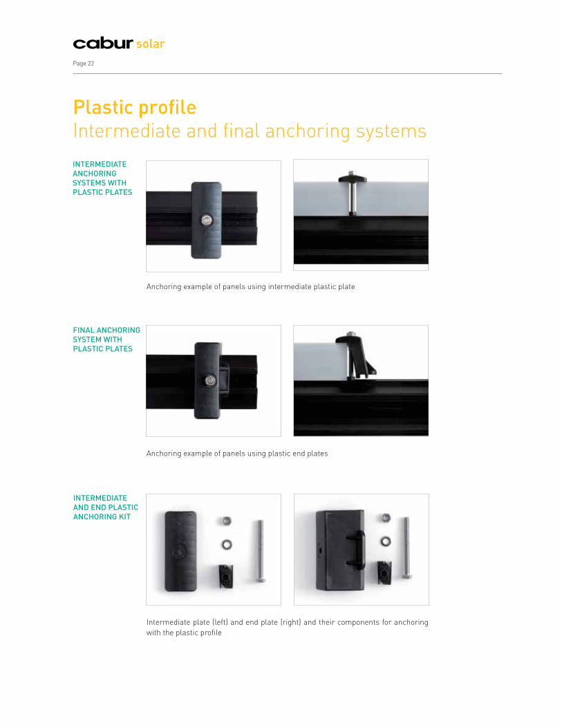
INTERMEDIATE
ANCHORING
SYSTEMS WITH
PLASTIC PLATES
INTERMEDIATE
AND END PLASTIC
ANCHORING KIT
FINAL ANCHORING
SYSTEM WITH
PLASTIC PLATES
Plastic profileIntermediate and final anchoring systems
Anchoring example of panels using intermediate plastic plate
Anchoring example of panels using plastic end plates
Intermediate plate (left) and end plate (right) and their components for anchoring
with the plastic profile

Cabur Solar Page 23
The anchoring of the photovoltaic panels with the profile
requires components to be selected based on the
characteristics of the system.
Select the number of plates by type (intermediate and end)
based on the number and arrangement of the panels and
strings
Select the model of the plates based on the material chosen
(plastic or stainless steel)
Select the type of end plates and screws based on the
thickness of the panels.
Plastic profileThe components
Code ISFIXCUR ISFIXAGL
Description Plastic sliding cursor to be inserted in the rail guide Roof corner fastener in stainless steel
Quantity per pack 100 20
OTHER COMPONENTS
Panel Thickness Intermediate Plate End Plate
in plastic in stainless steel in plastic in stainless steel
31 mm
ISFIXSPPLI ISFIXSPAZI
ISFIXSPPL31T ISFIXSPAZ31T
35 mm ISFIXSPPL35T ISFIXSPAZ35T
38 mm ISFIXSPPL38T ISFIXSPAZ38T
40 mm ISFIXSPPL40T ISFIXSPAZ40T
42 mm ISFIXSPPL42T ISFIXSPAZ42T
46 mm ISFIXSPPL46T ISFIXSPAZ46T
50 mm ISFIXSPPL50T ISFIXSPAZ50T
Code ISFIXVTAZ60 ISFIXVTAZ65 ISFIXVTAZ70 ISFIXVTAZ75
DescriptionM6 x 60 screw including
nut and washer
M6 x 65 screw including
nut and washer
M6 x 70 screw including
nut and washer
M6 x 75 screw including
nut and washer
Panel height (mm) 31 35-38 40-42 46-50
Quantity per pack 100 100 100 100
ANCHORING PLATES (in packs of 20 pieces)
FIXING SCREWS

Page 24
solar
Cabur Solar FixAccessories of the supports
Code ISFIXDAF ISFIXVLO ISFIXG
Description Stainless steel anti-theft tear-off nut. M6.
Stainless steel self-piercing and self-threading screw for attachment to all Cabur Solar Fix brackets for corrugated sheet metal roofs. L=25mm - Ø=1.8mm
Insulating rubber sheets, 110x130 mm
Quantity per pack 50 pieces per pack 500 pieces per pack 10 pieces per pack
Code ISFIXCLP ISFIXDUO
Description Clips for fastening wires to the profiles Union joint for profiles
Quantity per pack 100 pieces per pack 5 pieces per pack
SFIXDUOISFIXCLP

Cabur Solar
Photovoltaic systemsConnections and wiring
FROM PAGE 26 TO PAGE 50
A range of solutions for creating safe and reliable connections with the most common inverters / junction boxes.
26
27
29
30
34
36
37
38
42
43
44
45
47
48
49
50
Cabur Solar connectors. For connection with the most common inverters and junction boxes
Composition and materials
Electro-thermal tests
Line 3
Line 4
Accessories
Joint with MC connectors
Solarlok®connectors. For connection to Inverter and photovoltaic panels equipped with TYCO connectors
Connection to connectors. With Cabur Solar Y joints and Tyco mobile connectors
Tools for perfect photovoltaic connections
Tools. Matrices for crimper UMCT3149
Tools. Recommendations for correct use
First installation kit
Wires for small and large photovoltaic systems
Technical characteristics for FG21M21 IMQ certified wires
Technical characteristics for PV1-F TÜV certified wires

Page 26
solar
Fast, simple, and effective: connection in just three steps1. Insert the stripped wire into the contact to be crimped -CRIMP IT-.
2. Insert the wire complete with contact into the connector and push
hard until you hear the typical CLICK which indicates that the plastic
and metal parts are hooked together. Do not make any joints without
checking that the plastic and metal parts are hooked together.
3. Screw on the wire gland washer manually until it is firmly home to
guarantee IP67.
1
2
3
With Cabur Solar connectors, connections are simple and
effective for the most common inverters/junction boxes.
There are essentially two categories or groups:
Line 3, with 3mm diameter metal contacts;
Line 4, with 4mm diameter metal contacts;
These lines can in turn be divided into:
mobile connectors, male and female;
panel connectors, male and female;
Y connectors for forked lines;
caps and accessories.
All Cabur Solar connectors feature:
maximum voltage: 1,000 VDC;
contact resistance: ‹ 5 mΩ;
contact material: tin-plated copper;
insulation: PPO;
degree of protection: IP67 (IEC 60529);
temperature range: -40°C +85°C;
flammability class: UL94-V0.
To guarantee correct fixing according to standards, Cabur
recommends the use of the professional UMCT crimper,
together with the matrix IS3153 for Line 3 connectors and
IS3154 for Line 4 connectors, or the IS3161 crimper (see
pages 43-46).
To ensure the guarantee's effectiveness, the use of Cabur
Solar tools, in conformance with the standards and
instructions found in Cabur official documentation, is an
essential requirement.
The line includes mobile and panel connectors certified TÜV.
Cabur Solar connectorsFor connection with the most common inverters and junction boxes
ID : 20000000000

Cabur Solar Page 27
Line 3 and 4 mobile male-female connectors
These are composed of 4 basic parts (figs. 1 and 4):
1. A metallic contact known as a PIN (fig. 4) made of tin-
plated copper and formed using a moulding technique. It has
two wings necessary to anchor it to the electric wire. This
is done by crimping or mechanically, using matrix IS3153-
IS3154 in the relevant pliers UMCT3149, which, by bending
the wings on the metallic core of the photovoltaic wire (figs.
2, 3), ensures correct and safe anchoring in accordance with
CEI EN 60352-2. Perfect insulation of the metallic contact can
be further guaranteed by placing caps IS51400 and IS52400
onto the connector. The PIN can be male or female and have a
diameter of 3 or 4 mm. The male PIN with 3mm diameter has
a cap which insulates the head to ensure insulation degree
IP20. The male 4mm PIN, which remains deeply set into the
insulating cavity of the relative connector, does not need an
insulating cap (fig. 4).
2. A rubber washer for waterproofing the internal part of the
connector, preventing the penetration of external agents such
as humidity, dust, and oils, by squeezing the insulating sleeve
of the electric wire.
3. A rigid PPO plastic washer with a conical cavity that, after
being screwed onto the main body of the connector, forces the
reeds together, compressing the rubber sheath onto the wire
insulation and hence acting to help ensure IP67 protection
established on the basis of Technical Standard CEI EN 60529.
4. A main body made of PPO plastic which holds the metallic
PIN crimped onto the wire. The male connector holds the
male metallic contact (PIN) while the female connector holds
the female metallic contact (PIN). The male PIN penetrates
the female PIN (as for every other electrical-mechanical
connecting device), while the opposite is true for the plastic
connector (the insulating sleeve): the female penetrates the
male. For this reason, the outer surface of the female connector
of Line 3 has two red rubber rings which act as insulating
washers against the penetration of external atmospheric
agents. Similarly, the female connector of Line 4 has a red
rubber ring for the same purpose. The Line 3 connector,
being shorter, is more exposed to atmospheric agents and
for this reason is provided with a double ring, unlike Line 4
which has only one, as it can penetrate deeper into the relative
male and is hence better protected from outside agents.
The male and female connectors hook together mechanically
by means of two pointed anchored elastic wings on the female
connectors which must be inserted in the special slots on the
insulating body of the male connectors. Everything is rigidly
and firmly connected and accidental unhooking of the two
connectors, or the chance interruption of the line from the
photovoltaic field, is impossible. Disconnection is possible
only by pressing on the two male wings with the fingers and
simultaneously pulling the female out of the male manually,
without the aid of any tool.
Fig. 4 - series 3 (right hand pair) and series 4 (left hand pair) PINS
Cabur Solar connectorsComposition and materials
Fig. 1 - Exploded view of the panel connector body. The product is provided assembled)
Ocen crimp berrel
IEC 274705
Fig. 2 - Wire crimped onto PIN
Crimp barrel
Deformed wirestrands
IEC 274705
Fig. 3 - Wire crimped onto PIN

Page 28
solar
Fig. 5 – Exploded view of the connector body. The product is provided assembled.
Cabur Solar connectors
For panel connectors, always attach the
DO NO DISCONNECT UNDER LOAD sticker
near the connector on the surface of the box
where it will be fitted.
Fig. 6 - Exploded view of the rubber connector.
Male-female panel connectors of Lines 3 and 4
These are composed of 3 parts (fig. 5):
1. A metallic contact that is the same as the PIN on the
mobile version.
2. A main body made of PPO plastic holding the metallic PIN
crimped onto the wire which has a red rubber ring located
between the surface of the connector and the wall of the box
or sheet metal where the connector is installed. This ring
acts to create a compressed washer between the connector
and the panel able to protect both from being penetrated by
atmospheric agents and hence guaranteeing IP67 protection
as in CEI EN 60529. Compression of the insulating ring occurs
through tightening the relevant hexagonal nut to fix the panel.
The mobile male connectors are hooked to the female panel
connectors (or vice versa) as previously described for the
connection between flying connectors.Everything is rigidly
connected and there is no possibility of accidentally unhooking
the two connectors and accidentally breaking the line coming
from the photovoltaic system. Disconnection is only possible
by pressing the two male wings and simultaneously pulling
the female body out of the male body.
3. A hexagonal nut used to lock the connector against the
steel surface of the panel. These connectors are in plastic and
therefore the nut must not be tightened with too much force
otherwise the thread would immediately be flattened.
Rubber-plastic mobile connectors for Line 3
These are appropriate for connections to both mobile and
panel MC3 connectors. This means they can be used for
connections for both photovoltaic panels (if provided with
the appropriate retention hook), and for inverters (without
retention hook). Both connectors, male and female, consist of:
a metallic tin-plated copper PIN
a rubber-plastic insulating body
a washer to obtain IP67
a closing washer
As the main body of the connector is made of two materials,
it ensures speed and simplicity during assembly thanks
to the plastic side as well as universal joints thanks to the
rubber side. Using these connectors it is possible to connect
to any type of photovoltaic device (panel, inverter, string box,
etc.) and provide IP67 joints, with the use of Cabur Solar line
tools. The joint is done by following the same operations
provided for the other connectors of Line 3. The rubber side
has a series of grooves which when combined with the similar
grooves on the MC3 connectors, ensure their mechanical
retention. The presence of the retention hook which is lowered
onto the mobile MC3 connector guarantees an even stronger
mechanical coupling. The choice of hook will depend on the
dimensions of the MC3 connector to be used -- shorter for 40
mm mobile MC3 models and longer for 50 mm models.

Cabur Solar Page 29
Cabur Solar connectorsElectro-thermal tests
The electro-thermal tests carried out for various joints at the
KEMA labs in Holland demonstrate the efficiency of Cabur
Solar connectors.
The 5 images below show the results obtained from a joint
created by the male-female coupling of IS14240 and IS24241
connectors from Line 4.
The results were excellent. The joint, subjected to amperage
increasing from 10, to 20, 30, 40, and 50A did not show any
signs of overheating which could make usage dangerous.
The thermograms show a generally linear thermal gradient,
equal to 1°C/A such that, even for amperages which exceed
the maximum allowed 30 A, the joint remains "cold",
demonstrating low thermal generation due to the Joule
effect. Consequently, there is a low contact resistance and
hence low dissipation of electrical power, which has the final
consequence of increasing the overall performance of the
photovoltaic system. Similar results were obtained for all the
other joints, both for Line 3 and Line 4 connectors.
Fig. 1 - Thermogram at 10 A
Fig. 3 - Thermogram at 30 A
Fig. 2 - Thermogram at 20 A
Fig. 4 - Thermogram at 40 A
Fig. 5 - Thermogram at 50 A
WARNING!
The maximum usable current for all Cabur
Solar Line connectors is 25 A.
The thermograms shown here demonstrate
extreme situations which illustrate the
quality of the product. They are not intended
to suggest or guarantee project conditions.

Page 30
solar
ID : 20000000000 ID: 20000000000
ID: 20000000000 ID: 20000000000
Normal packaging: the code refers to packets composed of plastic and metal parts (outer shell + PIN)
Use On string boxes and/or inverters Extensions (wire/wire connections)
Code IS13112 IS23113 IS13242 IS23243
ID number KX03PM4060 KX03PF4060 KX03VM4060 KX03VF4060
Application Panel Panel Flying connector Flying connector
Connector type Male Female Male Female
PIN diameter 3 mm 3 mm 3 mm 3 mm
Section of crimpable wires 4 mm² 6 mm² 4 mm² 6 mm² 4 mm² 6 mm² 4 mm² 6 mm²
Pliers UMCT3149 UMCT3149 UMCT3149 UMCT3149
Matrix IS3153 IS3153 IS3153 IS3153
Features of metallic PIN Tin-plated copper Tin-plated copper Tin-plated copper Tin-plated copper
Contact resistance Rc ‹ 5 mΩ Rc ‹ 5 mΩ Rc ‹ 5 mΩ Rc ‹ 5 mΩ
PIN type Moulded Moulded Moulded Moulded
Shell features Plastic (PPO) Plastic (PPO) Plastic (PPO) Plastic (PPO)
Maximum applicable voltage 1,000 VDC 1,000 VDC 1,000 VDC 1,000 VDC
Maximum applicable current 25 A 25 A 25 A 25 A
Admitted operating
temperature range
- 40° ‹ T ‹ +85° - 40° ‹ T ‹ +85° - 40° ‹ T ‹ +85° - 40° ‹ T ‹ +85°
Degree of protection IP67 IP67 IP67 IP67
Flammability class UL94-V0 UL94-V0 UL94-V0 UL94-V0
Certifications obtained TÜV TÜV TÜV TÜV
Quantity per pack 100 100 100 100
Packaging One box contains 10 sachets. Every sachet contains 10 plastic shells and 10 metallic contacts (PINS)
Plastic shell only
Code ISPAN3M ISPAN3F ISVOL3M ISVOL3F
Packaging One packet contains 100 plastic shells
Metallic contact (PIN) only
Code ISPIN34060M ISPIN34060F ISPIN34060M ISPIN34060F
Packaging One packet contains 10 sachets and each sachet contains 10 PINS for a total of 100 PINS
Metallic contact on roll only
Code IS0701207 IS0701209 IS0701207 IS0701209
Packaging Ribbon with 2,000 PINS for wires with a 4 mm² or 6 mm²
section
Ribbon with 2,000 PINS for wires with a 4 mm² or 6 mm²
section
Pre-wired connectors available on demand. For information contact the Cabur sales network
Pre-wired connectors
For joints with MC connectors, see page 37 (except pre-wired connectors).
Cabur Solar connectors Line 3

Cabur Solar Page 31
Cabur Solar connectors Line 3
Normal packaging: the code refers to packets composed of plastic and metal parts (outer shell + PIN)
Use Only for connections with photovoltaic panels with short-
type MC3 (40 mm)
Only for connections with photovoltaic panels with long-
type MC3 (50 mm)
Code IS15240 IS25241 IS15242 IS25243
ID number KX03VM2540GC KX03VF2540GC KX03VM4060GL KX03VF4060GL
Application Flying connector with short retention hook Flying connector with long retention hook
Connector type Male Female Male Female
PIN diameter 3 mm 3 mm 3 mm 3 mm
Section of crimpable wires 2.5 mm² 4 mm² 2.5 mm² 4 mm² 4 mm² 6 mm² 4 mm² 6 mm²
Pliers UMCT3149 UMCT3149 UMCT3149 UMCT3149
Matrix IS3153 IS3153 IS3153 IS3153
Features of metallic PIN Tin-plated copper Tin-plated copper Tin-plated copper Tin-plated copper
Contact resistance Rc ‹ 5 mΩ Rc ‹ 5 mΩ Rc ‹ 5 mΩ Rc ‹ 5 mΩ
PIN type Moulded Moulded Moulded Moulded
Shell features Plastic (PPO) Plastic (PPO) Plastic (PPO) Plastic (PPO)
Maximum applicable voltage 1,000 VDC 1,000 VDC 1,000 VDC 1,000 VDC
Maximum applicable current 25 A 25 A 25 A 25 A
Admitted operating
temperature range
- 40° ‹ T ‹ +85° - 40° ‹ T ‹ +85° - 40° ‹ T ‹ +85° - 40° ‹ T ‹ +85°
Degree of protection IP67 IP67 IP67 IP67
Flammability class UL94-V0 UL94-V0 UL94-V0 UL94-V0
Certifications obtained - - - -
Quantity per pack 100 100 100 100
Packaging One box contains 10 sachets. Every sachet contains 10 plastic shells and 10 metallic contacts (PINS)
Plastic shell only
Code ISVOL3GM ISVOL3GF ISVOL3GML ISVOL3GFL
Packaging One packet contains 100 plastic shells
Metallic contact (PIN) only
Code ISPIN34060M ISPIN34060F ISPIN34060M ISPIN34060F
Packaging One packet contains 10 sachets and each sachet contains 10 PINS for a total of 100 PINS
Metallic contact on roll only
Code - - IS0701207 IS0701209
Packaging - Ribbon with 2,000 PINS for wires with a 4 mm² or 6 mm²
section
Pre-wired connectors available on demand. For information contact the Cabur sales network
Hooks
IS15000 short hook (1)
IS15001 long hook (2)
For joints with MC connectors, see page 37 (except pre-wired connectors).
(1) (2)

Page 32
solar
Cabur Solar connectors Line 3
Normal packaging: the code refers to packets composed of plastic and metal parts (outer shell + PIN)
Use For connections with photovoltaic panels with short-type
MC3 (40 mm) or to connect to inverters that use MC3
(remove the hook from the Cabur connector when it is
connected to the inverter)
For connections with photovoltaic panels with long-type
MC3 (50 mm) or to connect to inverters that use MC3
(remove the hook from the Cabur connector when it is
connected to the inverter)
Code IS15341 IS25342 IS15342 IS25343
ID number KX03VM4060GC KX03VF4060GC KX03VM4060GL KX03VF4060GL
Application Flying connector with short
retention hook
Flying connector with short
retention hook
Flying connector with long
retention hook
Flying connector with long
retention hook
Connector type Male Female Male Female
PIN diameter 3 mm 3 mm 3 mm 3 mm
Section of crimpable wires 4 mm² 6 mm² 4 mm² 6 mm² 4 mm² 6 mm² 4 mm² 6 mm²
Pliers UMCT3149 UMCT3149 UMCT3149 UMCT3149
Matrix IS3153 IS3153 IS3153 IS3153
Features of metallic PIN Tin-plated copper Tin-plated copper Tin-plated copper Tin-plated copper
Contact resistance Rc ‹ 5 mΩ Rc ‹ 5 mΩ Rc ‹ 5 mΩ Rc ‹ 5 mΩ
PIN type Moulded Moulded Moulded Moulded
Shell features Rubber-Plastic (PPO) Rubber-Plastic (PPO) Rubber-Plastic (PPO) Rubber-Plastic (PPO)
Maximum applicable voltage 1,000 VDC 1,000 VDC 1,000 VDC 1,000 VDC
Maximum applicable current 25 A 25 A 25 A 25 A
Admitted operating
temperature range
- 40° ‹ T ‹ +85° - 40° ‹ T ‹ +85° - 40° ‹ T ‹ +85° - 40° ‹ T ‹ +85°
Degree of protection IP67 IP67 IP67 IP67
Flammability class UL94-V0 UL94-V0 UL94-V0 UL94-V0
Certifications obtained - - - -
Quantity per pack 100 100 100 100
Packaging One box contains 10 sachets. Every sachet contains 10 plastic shells and 10 metallic contacts (PINS)
Plastic shell only
Code ISVOL3MGPGC ISVOL3FGPGC ISVOL3MGPGL ISVOL3FGPGL
Packaging One packet contains 100 plastic shells
Metallic contact only
Code ISPIN34060M ISPIN34060F ISPIN34060M ISPIN34060F
Packaging One packet contains 10 sachets and each sachet contains 10 PINS for a total of 100 PINS
Metallic contact on roll only
Code IS0701207 IS0701209 IS0701207 IS0701209
Packaging Ribbon with 2,000 PINS for wires with a 4 mm² or 6 mm²
section
Ribbon with 2,000 PINS for wires with a 4 mm² or 6 mm²
section
Pre-wired connectors available on demand. For information contact the Cabur sales network
Hooks
IS15000 short hook (1)
IS15001 long hook (2)
For joints with MC connectors, see page 37 (except pre-wired connectors).
(1) (2)

Cabur Solar Page 33
Cabur Solar Y connectors Line 3
Normal packaging: the code refers to packets composed of plastic and metal parts (outer shell + PIN)
Use To create parallel connections between strings of panels
with short-type MC3 connectors (40 mm)
To create parallel connections between strings of panels
with long-type MC3 connectors (50 mm)
Code IS41310S IS42320S IS41310L IS42320L
ID number KX03MFFGS KX03FMMGS KX03MFFGL KX03FMMGL
Application Flying connector Flying connector Flying connector Flying connector
Connector type Male/Female-Female Female/Male-Male Male/Female-Female Female/Male-Male
PIN diameter 3 mm 3 mm 3 mm 3 mm
Section of crimpable wires All All All All
Pliers NO NO NO NO
Matrix NO NO NO NO
Features of metallic PIN Tin-plated copper Tin-plated copper Tin-plated copper Tin-plated copper
Contact resistance Rc ‹ 5 mΩ Rc ‹ 5 mΩ Rc ‹ 5 mΩ Rc ‹ 5 mΩ
PIN type Moulded Moulded Moulded Moulded
Shell features Plastic (PPO) Plastic (PPO) Plastic (PPO) Plastic (PPO)
Maximum applicable voltage 1,000 VDC 1,000 VDC 1,000 VDC 1,000 VDC
Maximum applicable current 25 A 25 A 25 A 25 A
Admitted operating
temperature range
- 40° ‹ T ‹ +85° - 40° ‹ T ‹ +85° - 40° ‹ T ‹ +85° - 40° ‹ T ‹ +85°
Degree of protection IP67 IP67 IP67 IP67
Flammability class UL94-V0 UL94-V0 UL94-V0 UL94-V0
Certifications obtained - - - -
Quantity per pack 30 30 30 30
Packaging One box contains 6 sachets. Every sachet contains 5 Y joints.
Plastic shell only
Code - - - -
Packaging -
Metallic contact (PIN) only
Code - - - -
Packaging -
Metallic contact on roll only
Code - - - -
Packaging -
Pre-wired connectors available on demand. For information contact the Cabur sales network
Hooks
IS15000 short hook (1)
IS15001 long hook (2)
For joints with MC connectors, see page 37 (except pre-wired connectors).
(1) (2)
Page 34
solar
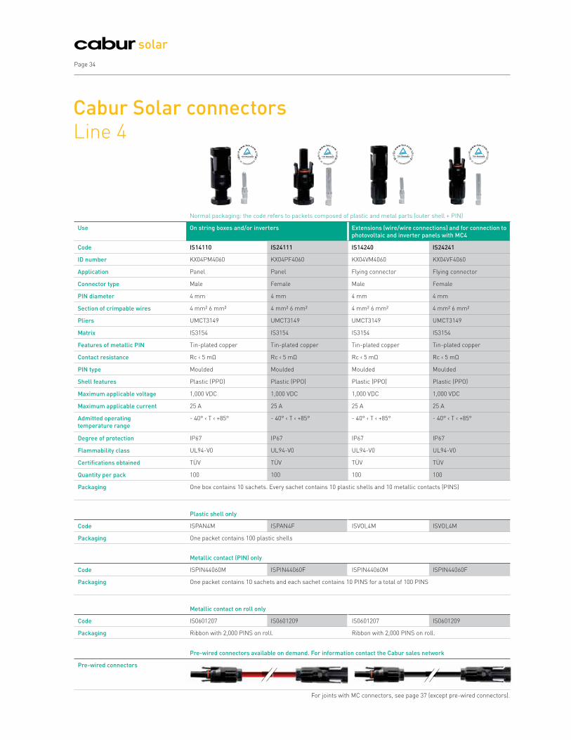
Cabur Solar connectors Line 4
ID : 20000000000ID: 20000000000 ID: 20000000000 ID: 20000000000
Normal packaging: the code refers to packets composed of plastic and metal parts (outer shell + PIN)
Use On string boxes and/or inverters Extensions (wire/wire connections) and for connection to
photovoltaic and inverter panels with MC4
Code IS14110 IS24111 IS14240 IS24241
ID number KX04PM4060 KX04PF4060 KX04VM4060 KX04VF4060
Application Panel Panel Flying connector Flying connector
Connector type Male Female Male Female
PIN diameter 4 mm 4 mm 4 mm 4 mm
Section of crimpable wires 4 mm² 6 mm² 4 mm² 6 mm² 4 mm² 6 mm² 4 mm² 6 mm²
Pliers UMCT3149 UMCT3149 UMCT3149 UMCT3149
Matrix IS3154 IS3154 IS3154 IS3154
Features of metallic PIN Tin-plated copper Tin-plated copper Tin-plated copper Tin-plated copper
Contact resistance Rc ‹ 5 mΩ Rc ‹ 5 mΩ Rc ‹ 5 mΩ Rc ‹ 5 mΩ
PIN type Moulded Moulded Moulded Moulded
Shell features Plastic (PPO) Plastic (PPO) Plastic (PPO) Plastic (PPO)
Maximum applicable voltage 1,000 VDC 1,000 VDC 1,000 VDC 1,000 VDC
Maximum applicable current 25 A 25 A 25 A 25 A
Admitted operating
temperature range
- 40° ‹ T ‹ +85° - 40° ‹ T ‹ +85° - 40° ‹ T ‹ +85° - 40° ‹ T ‹ +85°
Degree of protection IP67 IP67 IP67 IP67
Flammability class UL94-V0 UL94-V0 UL94-V0 UL94-V0
Certifications obtained TÜV TÜV TÜV TÜV
Quantity per pack 100 100 100 100
Packaging One box contains 10 sachets. Every sachet contains 10 plastic shells and 10 metallic contacts (PINS)
Plastic shell only
Code ISPAN4M ISPAN4F ISVOL4M ISVOL4M
Packaging One packet contains 100 plastic shells
Metallic contact (PIN) only
Code ISPIN44060M ISPIN44060F ISPIN44060M ISPIN44060F
Packaging One packet contains 10 sachets and each sachet contains 10 PINS for a total of 100 PINS
Metallic contact on roll only
Code IS0601207 IS0601209 IS0601207 IS0601209
Packaging Ribbon with 2,000 PINS on roll. Ribbon with 2,000 PINS on roll.
Pre-wired connectors available on demand. For information contact the Cabur sales network
Pre-wired connectors
For joints with MC connectors, see page 37 (except pre-wired connectors).

Cabur Solar Page 35
Cabur Solar connectors Line 4
conne rs
Normal packaging: the code refers to packets composed of plastic and metal parts (outer shell + PIN)
Use Extensions (wire/wire connections) and for connection to
photovoltaic and inverter panels with MC4
Y connectors
Code IS14242 IS24243 IS41410 IS42420
ID number KX04VM100 KX04VF100 KX04MFF KX04FMM
Application Flying connector Flying connector Flying connector Flying connector
Connector type Male Female Male/Female-Female Female/Male-Male
PIN diameter 4 mm 4 mm 4 mm 4 mm
Section of crimpable wires 10 mm² 10 mm² All All
Pliers UMCT3149 UMCT3149 NO NO
Matrix IS3110 IS3110 NO NO
Features of metallic PIN Tin-plated copper Tin-plated copper Tin-plated copper Tin-plated copper
Contact resistance Rc ‹ 5 mΩ Rc ‹ 5 mΩ Rc ‹ 5 mΩ Rc ‹ 5 mΩ
PIN type Shrouded Shrouded Moulded Moulded
Shell features Plastic (PPO) Plastic (PPO) Plastic (PPO) Plastic (PPO)
Maximum applicable voltage 1,000 VDC 1,000 VDC 1,000 VDC 1,000 VDC
Maximum applicable current 25 A 25 A 35 A 35 A
Admitted operating
temperature range
- 40° ‹ T ‹ +85° - 40° ‹ T ‹ +85° - 40° ‹ T ‹ +90° - 40° ‹ T ‹ +90°
Degree of protection IP67 IP67 IP67 IP67
Flammability class UL94-V0 UL94-V0 UL94-V0 UL94-V0
Certifications obtained TÜV pending TÜV pending - -
Quantity per pack 100 100 30 30
Packaging One box contains 10 sachets. Every sachet contains 10
plastic shells and 10 metallic contacts (PINS).
One box contains 6 sachets. Every sachet
contains 5 Y joints.
Plastic shell only
Code - - - -
Packaging
Metallic contact (PIN) only
Code - - - -
Packaging
Metallic contact on roll only
Code - - - -
Packaging
Pre-wired connectors available on demand. For information contact the Cabur sales network
Pre-wired connectors
For joints with MC connectors, see page 37 (except pre-wired connectors).
Page 36
solar
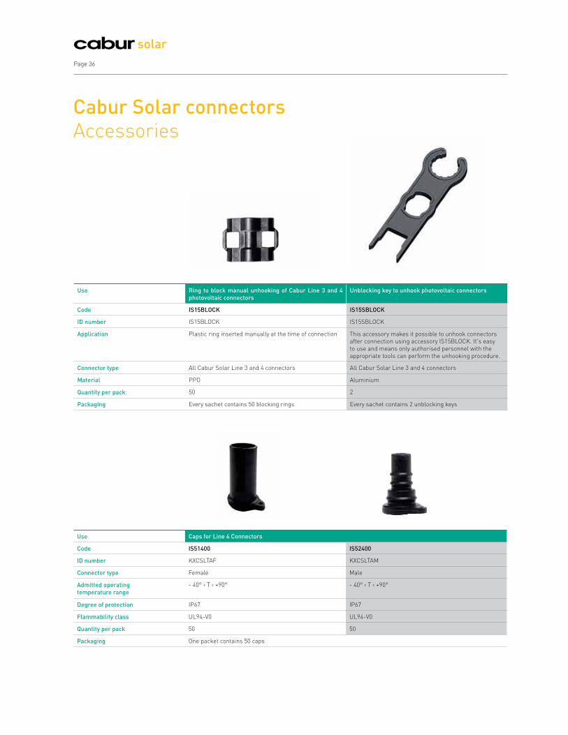
Cabur Solar connectors Accessories
Use Ring to block manual unhooking of Cabur Line 3 and 4
photovoltaic connectors
Unblocking key to unhook photovoltaic connectors
Code IS15BLOCK IS15SBLOCK
ID number IS15BLOCK IS15SBLOCK
Application Plastic ring inserted manually at the time of connection This accessory makes it possible to unhook connectors
after connection using accessory IS15BLOCK. It's easy
to use and means only authorised personnel with the
appropriate tools can perform the unhooking procedure.
Connector type All Cabur Solar Line 3 and 4 connectors All Cabur Solar Line 3 and 4 connectors
Material PPO Aluminium
Quantity per pack 50 2
Packaging Every sachet contains 50 blocking rings Every sachet contains 2 unblocking keys
Use Caps for Line 4 Connectors
Code IS51400 IS52400
ID number KXCSLTAF KXCSLTAM
Connector type Female Male
Admitted operating
temperature range
- 40° ‹ T ‹ +90° - 40° ‹ T ‹ +90°
Degree of protection IP67 IP67
Flammability class UL94-V0 UL94-V0
Quantity per pack 50 50
Packaging One packet contains 50 caps
Cabur Solar Page 37
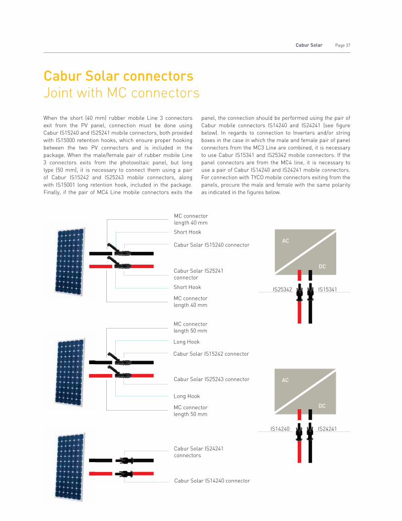
When the short (40 mm) rubber mobile Line 3 connectors
exit from the PV panel, connection must be done using
Cabur IS15240 and IS25241 mobile connectors, both provided
with IS15000 retention hooks, which ensure proper hooking
between the two PV connectors and is included in the
package. When the male/female pair of rubber mobile Line
3 connectors exits from the photovoltaic panel, but long
type (50 mm), it is necessary to connect them using a pair
of Cabur IS15242 and IS25243 mobile connectors, along
with IS15001 long retention hook, included in the package.
Finally, if the pair of MC4 Line mobile connectors exits the
panel, the connection should be performed using the pair of
Cabur mobile connectors IS14240 and IS24241 (see figure
below). In regards to connection to Inverters and/or string
boxes in the case in which the male and female pair of panel
connectors from the MC3 Line are combined, it is necessary
to use Cabur IS15341 and IS25342 mobile connectors. If the
panel connectors are from the MC4 line, it is necessary to
use a pair of Cabur IS14240 and IS24241 mobile connectors.
For connection with TYCO mobile connectors exiting from the
panels, procure the male and female with the same polarity
as indicated in the figures below.
Cabur Solar IS24241
connectors
MC connector
length 40 mm
Short Hook
Cabur Solar IS15240 connector
Cabur Solar IS25241
connector
Short Hook
MC connector
length 40 mm
MC connector
length 50 mm
Long Hook
Cabur Solar IS15242 connector
Cabur Solar IS25243 connector
Long Hook
MC connector
length 50 mm
Cabur Solar IS14240 connector
AC
DC
IS25342 IS15341
AC
DC
IS14240 IS24241
Cabur Solar connectorsJoint with MC connectors

Page 38
solar
Solarlok®
connectorsFor connection to inverters and photovoltaic panels equipped with TYCO connectors
Solarlok® delivers a flexible, easy-to-use system solution
for reliable interconnections from solar modules to the
inverter. The entire concept is based on the reliable and
efficient management of individual interconnecting system
components.
The security of the coupling is guaranteed by polarity keyed
housings, shrouded and silver plated contacts to be crimped,
and a connection system with release on the application of
pressure. In addition, the wide operating temperature range
and fulfilment of worldwide standards for photovoltaic
connection systems make these products strong and reliable.
Apart from the 4 and 6 mm2 connectors, the Cabur offer
includes a set of professional tools, for specific use with
Solarlok connectors and a first-installation KIT complete
with all necessary accessories for connecting a photovoltaic
system.
SOLARLOK®; TE and Tyco Electronics are registered trademarks.
Technical features
Secure coupling achieved using coding
keys
Multiple insertion and removal cycles
Wide operating temperature range
-40 °C ‹ T ‹ +90 °C
TÜV and UL approved
Continuous 1,000 VDC voltage
Continuous 25A current
IP 67 protection degree

Cabur Solar Page 39
Normal packaging: the code refers to packets composed of plastic and metal parts (outer shell + PIN)
Application For connection to photovoltaic panels (to create
simple joints and/or extensions use male and
female connectors with the same polarity)
For connection to photovoltaic panels (to create
simple joints and/or extensions use male and
female connectors with the same polarity)
For connection to
female connectors,
both positive and
negative
Code IS401394462 IS301394461 IS301394462 IS401394461 IS261394461
ID number KXSUN04FPNEG KXSUN04MPPOS KXSUN04FPPOS KXSUN04MPNEG KXSUN04MPNEU
Application Flying connector Flying connector Flying connector Flying connector Flying connector
Polarity Negative Positive Positive Negative Positive-Negative
Connector type Female Male Female Male Male
PIN diameter 2.5 mm 2.5 mm 2.5 mm 2.5 mm 2.5 mm
Section of crimpable wires 4 mm² 4 mm² 4 mm² 4 mm² 4 mm²
Pliers UMCT3149 UMCT3149 UMCT3149 UMCT3149 UMCT3149
Matrix IS3152 IS3152 IS3152 IS3152 IS3152
Features of metallic PIN Tin-plated copper Tin-plated copper Tin-plated copper Tin-plated copper Tin-plated copper
Contact resistance Rc ‹ 5 mΩ Rc ‹ 5 mΩ Rc ‹ 5 mΩ Rc ‹ 5 mΩ Rc ‹ 5 mΩ
PIN type Shrouded Shrouded Shrouded Shrouded Shrouded
Shell features Plastic (PPO) Plastic (PPO) Plastic (PPO) Plastic (PPO) Plastic (PPO)
Maximum applicable voltage 1,000 VDC 1,000 VDC 1,000 VDC 1,000 VDC 1,000 VDC
Maximum applicable current 25 A 25 A 25 A 25 A 25 A
Admitted operating
temperature range
- 40° ‹ T ‹ +90° - 40° ‹ T ‹ +90° - 40° ‹ T ‹ +90° - 40° ‹ T ‹ +90° - 40° ‹ T ‹ +90°
Degree of protection IP67 IP67 IP67 IP67 IP67
Flammability class UL94-V0 UL94-V0 UL94-V0 UL94-V0 UL94-V0
Certifications obtained TÜV & UL TÜV & UL TÜV & UL TÜV & UL TÜV & UL
Quantity per pack 100 100 100 100 100
Packaging Every packet contains 100 plastic shells and 100
metallic contacts (PINS)
Every packet contains 100 plastic shells and 100
metallic contacts (PINS)
Every packet contains
100 plastic shells and
100 metallic contacts
(PINS)
Solarlok®
connectorsFor connection to inverters and photovoltaic panels equipped with TYCO connectors
SOLARLOK®; TE and Tyco Electronics are registered trademarks.

Page 40
solar
Normal packaging: the code refers to packets composed of plastic and metal parts (outer shell + PIN)
Application On string boxes and/or inverters For connection to photovoltaic panels (to create
simple joints and/or extensions use male and
female connectors with the same polarity)
For connection to
female connectors,
both positive and
negative
Code IS301394738 IS401394738 IS651394462 IS651394461 IS461394461
ID number KXSUNDCAC4POS KXSUNDCAC4NEG KXSUN06FPNEG KXSUN06MPPOS KXSUN06MPNEU
Application Panel Panel Flying connector Flying connector Flying connector
Polarity Positive Negative Negative Positive Positive-Negative
Connector type Male Male Female Male Male
PIN diameter 2.5 mm 2.5 mm 2.5 mm 2.5 mm 2.5 mm
Section of crimpable wires 4 mm² 4 mm² 6 mm² 6 mm² 6 mm²
Pliers UMCT3149 UMCT3149 UMCT3149 UMCT3149 UMCT3149
Matrix IS3152 IS3152 IS3152 IS3152 IS3152
Features of metallic PIN Tin-plated copper Tin-plated copper Tin-plated copper Tin-plated copper Tin-plated copper
Contact resistance Rc ‹ 5 mΩ Rc ‹ 5 mΩ Rc ‹ 5 mΩ Rc ‹ 5 mΩ Rc ‹ 5 mΩ
PIN type Shrouded Shrouded Shrouded Shrouded Shrouded
Shell features Plastic (PPO) Plastic (PPO) Plastic (PPO) Plastic (PPO) Plastic (PPO)
Maximum applicable voltage 1,000 VDC 1,000 VDC 1,000 VDC 1,000 VDC 1,000 VDC
Maximum applicable current 25 A 25 A 25 A 25 A 25 A
Admitted operating
temperature range
- 40° ‹ T ‹ +90° - 40° ‹ T ‹ +90° - 40° ‹ T ‹ +90° - 40° ‹ T ‹ +90° - 40° ‹ T ‹ +90°
Degree of protection IP67 IP67 IP67 IP67 IP67
Flammability class UL94-V0 UL94-V0 UL94-V0 UL94-V0 UL94-V0
Certifications obtained TÜV & UL TÜV & UL TÜV & UL TÜV & UL TÜV & UL
Quantity per pack 100 100 100 100 100
Packaging Every packet contains 10 plastic shells and 10
metallic contacts (PIN)
Every packet contains 100 plastic shells and 100
metallic contacts (PINS)
Every packet contains
100 plastic shells and
100 metallic contacts
(PINS)
SOLARLOK®; TE and Tyco Electronics are registered trademarks.
Solarlok®
connectorsFor connection to inverters and photovoltaic panels equipped with TYCO connectors
NOTE
IS651394462and IS461394461 codes are available while stocks last.Contact the Sales Office to verify the substitute articles.

Cabur Solar Page 41
Solarlok®
connectorsFor connection to inverters and photovoltaic panels equipped with TYCO connectors
Normal packaging: the code refers to packets composed of plastic and metal parts (outer shell + PIN)
For connection to photovoltaic panels (to create
simple joints and/or extensions use male and
female connectors with the same polarity)
For the creation of parallel connections between
strings
For the creation of parallel connections between
strings
IS551394462 IS661394461 IS101534611 IS201534611 IS101740277 IS201740277
KXSUN06FPPOS KXSUN06MPNEG KXSUNPOSSMM KXSUNNEGSMM KXSUNPOSPFM KXSUNNEGPFM
Flying connector Flying connector Flying connector Flying connector Flying connector Flying connector
Positive Negative Positive Negative Positive Negative
Female Male Male/Male-Male Male/Male-Male Female/Male-Male Female/Male-Male
2.5 mm 2.5 mm 2.5 mm 2.5 mm 2.5 mm 2.5 mm
6 mm² 6 mm² 4 mm² and 6 mm² 4 mm² and 6 mm² 4 mm² and 6 mm² 4 mm² and 6 mm²
UMCT3149 UMCT3149 NO NO NO NO
IS3152 IS3152 NO NO NO NO
Tin-plated copper Tin-plated copper Tin-plated copper Tin-plated copper Tin-plated copper Tin-plated copper
Rc ‹ 5 mΩ Rc ‹ 5 mΩ Rc ‹ 5 mΩ Rc ‹ 5 mΩ Rc ‹ 5 mΩ Rc ‹ 5 mΩ
Shrouded Shrouded Shrouded Shrouded Shrouded Shrouded
Plastic (PPO) Plastic (PPO) Plastic (PPO) Plastic (PPO) Plastic (PPO) Plastic (PPO)
1,000 VDC 1,000 VDC 1,000 VDC 1,000 VDC 1,000 VDC 1,000 VDC
25 A 25 A 25 A 25 A 25 A 25 A
- 40° ‹ T ‹ +90° - 40° ‹ T ‹ +90° - 40° ‹ T ‹ +90° - 40° ‹ T ‹ +90° - 40° ‹ T ‹ +90° - 40° ‹ T ‹ +90°
IP67 IP67 IP67 IP67 IP67 IP67
UL94-V0 UL94-V0 UL94-V0 UL94-V0 UL94-V0 UL94-V0
TÜV & UL TÜV & UL TÜV & UL TÜV & UL TÜV & UL TÜV & UL
100 100 100 100 100 100
Every packet contains 100 plastic shells and 100
metallic contacts (PINS)
Every sachet contains 10 Y joints Every sachet contains 10 Y joints
SOLARLOK®; TE and Tyco Electronics are registered trademarks.
NOTE
IS551394462and IS661394461 codes are available while stocks last.Contact the Sales Office to verify the substitute articles.

Page 42
solar
Connection to connectors
For connection with TYCO mobile connectors exiting from the
panels, procure the male and female with the same polarity as
indicated in the figures below.
Connection with Cabur Solar Y joints
Connection with Tyco mobile connectors
Y joints are particularly useful for coupling the strings of
panels in amorphous technology (thin film), where there are
often parallel connections on the line leading to the inverter.
They are therefore connections with low current and high
voltage, typical with thin film.
IS301394461 SC Ø = 4 mm2
IS651394461 SC Ø = 6 mm2
IS301394462 SC Ø = 4 mm2
IS551394462 SC Ø = 6 mm2
IS401394462 SC Ø = 4 mm2
IS651394462 SC Ø = 6 mm2
IS401394462 SC Ø = 4 mm2
IS651394462 SC Ø = 6 mm2
IS401394461 SC Ø = 4 mm2
IS661394461 SC Ø = 6 mm2
IS301394462 SC Ø = 4 mm2
IS551394462 SC Ø = 6 mm2
solar array +ve solar array -ve
CASE A Photovoltaic panel with exit wires, O-ring on the red female connector
CASE B Photovoltaic panel with exit wires, O-ring on the blue female connector
CASE C Photovoltaic panel with junction box with no exit wires

Cabur Solar Page 43
To guarantee a result conforming to standard, in terms of
the security of the connection and insulation degree, it is
important to use suitable tools, according to the type of wire
and connectors used.
Cabur wire strippers and crimpers are especially chosen
to perform the specific operations with ease, in safety and
according to the technical requisites of the most efficient
photovoltaic systems.
To ensure the guarantee's effectiveness, the use of Cabur
Solar tools, in conformance with the standards and
instructions found in Cabur official documentation, is an
essential requirement.
Tools For perfect photovoltaic connections
Advantages of Cabur crimpers
Fixed matrix crimper IS3161
1. Recommended for simple and quick crimping
2. Tool for small systems
Interchangeable matrix crimper UMCT3149
1. Ideal for high-precision photovoltaic crimping,
thanks to a lateral locating device that ensures
correct positioning of the PIN and the form of
the clamping indentations for perfect crimping.
2. Thanks to the interchangeable matrices, it can also
be used to crimp ring, spade tongue terminals, closed
end slices, and other wire terminals (see page 44 for
more detail).
Advantages of Cabur wire strippers
Wire stripper IS31579002
1. It's well-built and robust,
appropriate for thousands of cycles
2. It acts simultaneously on both the sheaths
of the solar wire, cutting them precisely.
3. Allows for precise calibration of the length of the
stripping, thanks to an adjustable mobile cursor.
4. The blades exercise a defined cutting pressure, in fact
they are provided with attrition to protect the strands.
5. It can also be used to strip other wires.
Wire stripper IS3170
1. Light, affordable, and pocket-sized.
Code IS31579002
ID number KXCSLSPE
Description Cabur Solar wire
stripper
Pieces PK One
Code UMCT3149
ID number UMCT
Description Crimp tool with
interchangeable
matrix (select matrix
according to use)
Pieces PK One
Matrices see next page
SOLARLOK®; TE and Tyco Electronics are registered trademarks.
Code IS3110
ID number KXCRI10
Description Crimper for
CaburSolar 10 mm2
Pieces PK One
Code IS3170
ID number IS3170
Description Pocket Cabur Solar
wire stripper
Pieces PK One
Accessory Spare blade code
IS3170L
Code IS301102855
ID number KXSUNESTRAT
Description Solarlok extraction tool®
by Tyco Electronics
Pieces PK One
Code IS3161
ID number KXCRI2506
Description Crimp tool for Cabur
Solar connectors
complete with matrix
for wires with section
2.5 - 4 or 6 mm2
Pieces PK One

Page 44
solar
Matrix
Pliers
Wire Stripping
Technical Standard CEI EN 60352-2 (Stapled
connections - General rules, test methods and practical
guide) leads to a stripped length of about 8 mm for our
PIN contacts on both Line 3 and Line 4. Appropriate use
of Cabur wire strippers guarantees optimal stripping
(see instructions below).
Crimping with UMCT3149
The UMCT3149 crimper is designed for high precision
photovoltaic crimping and therefore has a lateral
positioner which ensures correct positioning of the
PIN. The positioner is screwed onto all the matrices
and, if necessary, can be removed. The geometry of
the clamping indentations ensures highly effective
crimping. Thanks to the interchangeable matrices, the
UMCT3149 can also be used for crimping ring, spade
tongue terminals, closed end slices, and other wire
terminals used for normal wiring of electrical panels
and for automation. For matrix substitution, please see
the diagram on the next page. Thanks to the marks on
the matrix, it's easy to correctly position the PIN for
each contact: the wire section is indicated on the lower
part and the PIN diameter on the upper part. Every
matrix gives a specific crimp. Let's see which, using the
example case of matrix IS3153 for the PIN Cabur Solar
Line 3 (the use of matrices IS3154 for the PIN Cabur
Solar Line 4 and IS3152 for PIN Solarlok® is similar).
With matrix IS3153 , it is possible to crimp only Line 3
PINS, on all wire sections, using:
the first indentation on the right is for the wire with a
2.5 mm² section;
the second indentation in the middle is for the wire
with a 4 mm² section;
the third indentation on the left is for the wire with a
6 mm² section.
Tools Matrices for crimper UMCT3149
SOLARLOK®; TE and Tyco Electronics are registered trademarks.
Matrix Code ID number Contact type Section Wire Pieces PK
IS3152 IS3152 Solarlok® by Tyco Electronics 2.5 - 4 or 6 mm2 One
IS3153 IS3153 Cabur Solar Line 3 2.5 - 4 or 6 mm2 One
IS3154 IS3154 Cabur Solar Line 4 2.5 - 4 or 6 mm2 One
UMCT3127 UMCT3127 Closed end slices 0.2 - 10 mm2 One
UMCT3153 UMCT3153 Closed end slices 16 - 25 mm2 One
UMCT3154 UMCT3154 Closed end slices 35 - 50 mm2 One
UMCT3129 UMCT3129 Ring and spade tongue terminals 1.5 - 2.5 mm2 One
UMCT3128 UMCT3128 Ring and spade tongue terminals 4 - 6 mm2 One

Cabur Solar Page 45
ToolsRecommendations for correct use
How to strip wire using IS31579002
1 2 3
1. The wire stripper works like a guillotine, suitable for wires of various thicknesses, allowing for fast and safe stripping.
2. It acts simultaneously on both the sleeves of the photovoltaic wire, cutting them precisely.
3. The blades move parallel to the wire, expelling the sheared off sleeve.
This wire stripper is able to strip wires with sections of 2.5, 4, 6 and 10 mm2. It is fitted with an end stop and allows for a
stripped constant length of approx. 8 mm, compliant with the requirements of our PINS. The blade can be replaced.
To strip wires with a 2.5 mm2 section, the blade must make a complete turn around the external perimeter of the wire.
To strip wires with a 4 mm2 section, the blade must make two complete turns around the external perimeter of the wire.
To strip wires with a 6 mm2 section, the blade must make three complete turns around the external perimeter of the wire.
In order to preserve the number of strands, the blade should not be turned more times than those indicated in the
recommendations above for each wire section.
Stripping with IS3170
x~1-3

ToolsRecommendations for correct use
Page 46
solar
Page 46
How to change the UMCT Crimper matrix
Open the pliers as wide as possible (fig. 1);
slowly bring the two levers of the pliers together, until the
locking/release mechanism makes three clicks (fig. 2);
observe the anchorage pin on the matrix (fig. 2);
insert the matrix, moving the anchorage pin towards the
internal part of the pliers chamber (fig.3);
make sure that the plastic tooth has locked the matrix in
place or that it has risen (fig.4);
press the two levers of the pliers, closing them as tightly as
possible (fig.4);
release the handles; the pliers should open automatically
and completely (fig.5);
if, when the pliers are closing, you realise that the crimping
is not successful or the crimp tool is blocked for any reason,
it can be released by pressing and releasing the handles a few
times and simultaneously pressing with your thumb on the
release lever on the internal part of the handle (fig.6).
1 2 3
654
How to crimp
Example of use of the IS3161 crimper for Cabur Solar connectors.

Cabur Solar Page 47
First installation kitCabur Solar Line 3, 4 and Solarlok
®
CODE ISKIT03A CODE ISKIT04 CODE ISKITYCO
ID number SUNKIT03A ID number SUNKIT04 ID number SOLARBOX
Kit composition Kit composition Kit composition
Code ID number Pieces PK Code ID number Pieces PK Code ID number Pieces PK
IS15240 KX03VM2540GC 20 IS14240 KX04VM4060 20 IS261394461 KXSUN04MPNEU 40
IS25241 KX03VF2540GC 20 IS24241 KX04VF4060 20 IS301394462 KXSUN04FPPOS 20
IS13112 KX03PM4060 10 IS14110 KX04PM4060 10 IS401394462 KXSUN04FPNEG 20
IS23113 KX03PF4060 10 IS24111 KX04PF4060 10 IS301102855 KXSUNESTRAT 1
IS41310S KX03MFFGS 5 IS41410 KX04MFF 5 IS211579002 KXSUNSPESPE 1
IS42320S KX03FMMGS 5 IS42420 KX04FMM 5 UMCT3149 UMCT 1
UMCT3149 UMCT 1 UMCT3149 UMCT 1 IS3152 IS3152 1
IS3153 IS3153 1 IS3154 IS3154 1 _ _ _
The first-installation KIT ISKIT03A includes a selection of
Cabur Solar Line 3 photovoltaic connectors and the necessary
tools for properly crimping solar wires with 2.5 mm², 4 mm²,
and 6 mm² sections.
The first-installation KIT ISKIT04 includes a selection of
Cabur Solar Line 4 photovoltaic connectors and the necessary
tools for properly crimping solar wires with 4 mm², and 6 mm²
sections.
The first-installation KIT ISKITYCO contains a selection of
photovoltaic connectors from the Solarlok® line by TycoTM and
the necessary tools for crimping solar wires with 4 mm², and
6 mm² sections.
The contents of each Kit can be seen in the table below. Every
kit is contained in a professional tool box, and does not include
the wires.
Any other tools not included, can be added to the Kit.
Technical details of the single components are given on the
relative pages.
SOLARLOK®; TE and Tyco Electronics are registered trademarks.

Page 48
solar
WiresFor photovoltaic systemsboth small and large
Pre-wired cables
To connect the panels within the string, Cabur offers a range
of solutions composed of Line 3 and Line 4 mobile connectors
on black and red 4mm² and 6mm² wires.
Any other combination of section, colour, length and type of
final connector is available in any quantity you need. For a
customised quote contact the Cabur sales network
Single pole wire with flexible conductor in tin-plated
copper class 5
First insulation G21 special HEPR type
Second Halogen Free Type Elastometric blend insulation
M21
For specific use with photovoltaic systems with
nominal voltage of UO/U = 600/1,000 VAC under alternating
current and not exceeding UO/U = 900/1,500 VDC under DC
Non-flame propagating
Halogen free
Designed for a useful lifetime of at least 25 years
Resistant to UV rays, water, ozone, salts, fluids, and
atmospheric agents in general
Standard colours: Black and Red
The following are available on-demand:
1.5 mm² section copper wires
16 to 240 mm² section copper wires
IMQ certified copper wires with sections from 4 to 6 mm² in
1,000 m spools
Copper wires with 10 mm2 sections in 1,000 m spools
(certified IMQ or TÜV)
UL certified copper wires
Copper wires with blue insulation
TÜV certified wires
Aluminium wires
For times, min. quantities and packaging costs, contact the
Cabur Sales Office.
Code ISCS02100 ISCS02101 ISCS02500 ISCS02501 ISCS04100 ISCS04101 ISCS04400
ID number KXCSOL2N100 KXCSOL2R100 KXCSOL2N500 KXCSOL2R500 KXCSOL4N100 KXCSOL4R100 KXCSOL4N400
Section 2.5 mm2 2.5 mm2 2.5 mm2 2.5 mm2 4 mm2 4 mm2 4 mm2
Colour Black Red Black Red Black Red Black
Packaging type Skein Skein Spool Spool Skein Skein Spool
Length 100 m 100 m 500 m 500 m 100 m 100 m 400 m
Code ISCS04401 ISCS06100 ISCS06101 ISCS06300 ISCS06301 ISCS10200 ISCS10201
ID number KXCSOL4R400 KXCSOL6N100 KXCSOL6R100 KXCSOL6N300 KXCSOL6R300 KXCSOL10N200 KXCSOL10R200
Section 4 mm2 6 mm2 6 mm2 6 mm2 6 mm2 10 mm2 10 mm2
Colour Red Black Red Black Red Black Red
Packaging type Spool Skein Skein Spool Spool Spool Spool
Length 400 m 100 m 100 m 300 m 300 m 200 m 200 m
IMQ certified wires - FG21M21

Cabur Solar Page 49
Electrical tests
Conductor electrical resistance EN 50395 art. 5
Voltage tests on finished wires EN 50395 art. 6
Flaw-free insulation EN 50395 art. 10
Sleeve surface resistance EN 50395 art. 11
Insulation resistance on complete wire CEI 20-13 art. 3.2.03
– at 20°C
– at 90°C
Stability under direct current EN 50305 art. 6.7
Verification of construction and dimension prescriptions
Verification of conformance Visual exam and
to construction prescriptions manual tests
Measurement of insulation thickness EN 50396 art. 4.1
Measurement of sleeve thickness EN 50396 art. 4.2
Measurement of external dimensions: EN 50396 art. 4.4
- average value
- ovalisation
Mechanical properties of insulation
Traction resistance test before ageing EN 60811-1-1
Traction resistance test after ageing EN 60811-1-2
Lengthening under heat EN 60811-2-1
Water absorption test EN 60811-1-3
Mechanical properties of sleeve
Traction resistance test before ageing EN 60811-1-1
Traction resistance test after ageing EN 60811-1-2
Lengthening under heat EN 60811-2-1
Water absorption test EN 60811-1-3
Compatibility test EN 60811-1-2
Tests at low temperature
Sleeve bending test EN 60811-1-4 art. 8.1
Sleeve lengthening test EN 60811-1-4 art. 8.2
Shock resistance test EN 60811-1-4 art. 8.5
Ozone resistance test EN 50395 art. 8.1.3
UV resistance test HD 605/A1 art.2.4.20
Reaction to fire CEI 20-35/1-2
Evaluation of halogens
Determination of Hcl quantity CEI 20-37/2-1
Determination of gas corrosiveness CEI 20-37/2-2
Laboratory tests carried out by IMQ for wire
certifications
Technical characteristics for FG21M21 IMQ certified wires
Continuous operating temperature: -40° + 90°C
Maximum operating temperature of the metallic
core: 90°C
Minimum operating temperature: -25°C
Temperature peak: 250°C
Lifetime: 25 years, provided that the temperature of
the metallic core never exceeds 90°C
Test voltage in alternate current: 6,500 V
Test voltage in direct current: 15,000 V
Minimum radius curve: 4 times external diameter
Breakage point under traction: 50 N/mm²
Standard colours: Black, Red
Approvals
IMQ Conforming to RoHS
1st insulation: HEPR type
G21 special2nd insulation: Elastometric compound
Halogen Free type M21
Flexible
conductor made
of tin-plated
copper, class 5,
conforming to
CEI 60227

Page 50
solar
Technical characteristics of PV1-F wires certified TÜV
Ozone resistance EN 50396 part 8.1.3
Resistance to UV rays HD605/A1 part 2.4.20
Vertical flame propagation test CEI EN 60332-1-2
High temperature pressure test
on complete wire EN 60811-3-1
Halogen content CEI EN 50267-2-1,
CEI EN 50267-2-2, EN 6084-2
Electrical resistance CEI 20-29 EN60228 CL.5
Reference regulations: TÜV 2 Pfg 1169/08.2007
Laboratory tests carried out by TÜV
for wire certifications
Operating temperature: -40°C + 90°C
Max. short circuit temperature: +200°C (5s max)
Lifetime: 25 years
Test voltage in alternate current: 6,500 V
Test voltage in direct current: 15,000 V
Uo/U nominal voltage; 0.6/1 kV AC; 1.8kV DC
Minimum radius curve: mobile installation 15 x wire diameter fixed installation 6 x wire diameter
Insulation resistance: ›1014 Ω x cm at 20°C
Standard colours: Black, Red
ID : 20000000000
Halogen-free elastomer insulation
conforming to TÜV Pfg 1169/08.2007 - CEI
EN 50363 (CEI 20-11)
Halogen-free external sleeve in elastomer
or rubber conforming to TÜV Pfg
1169/08.2007 - CEI EN 50363 (CEI 20-11)
Tin-plated copper conductor, class 5,
conforming to CEI EN 60228 (CEI 20-29)

Cabur Solar
Photovoltaic systemsString boxes, control units and their components
FROM PAGE 52 TO PAGE 89
To connect strings, the monitoring of the efficiency of the installation and the distribution of the current in small, medium and large size photovoltaic systems.
52
53
56
63
66
71
76
77
84
84
85
87
88
89
Connection diagram of the modules and strings of a photovoltaic generator
StringBox connection panels
StringBox control units for PV arrays
ISL series DC/AC control units for PV arrays
E-Box. String and monitoring boxes with electronics for monitoring
E-Box. Components
E-Box. Ordering codes table
Surge Protection Devices
Components for string boxes
Boxes for control units
Boxes for distribution panels
Switches and disconnectors
Fuse holders and fuses
Blocking diode
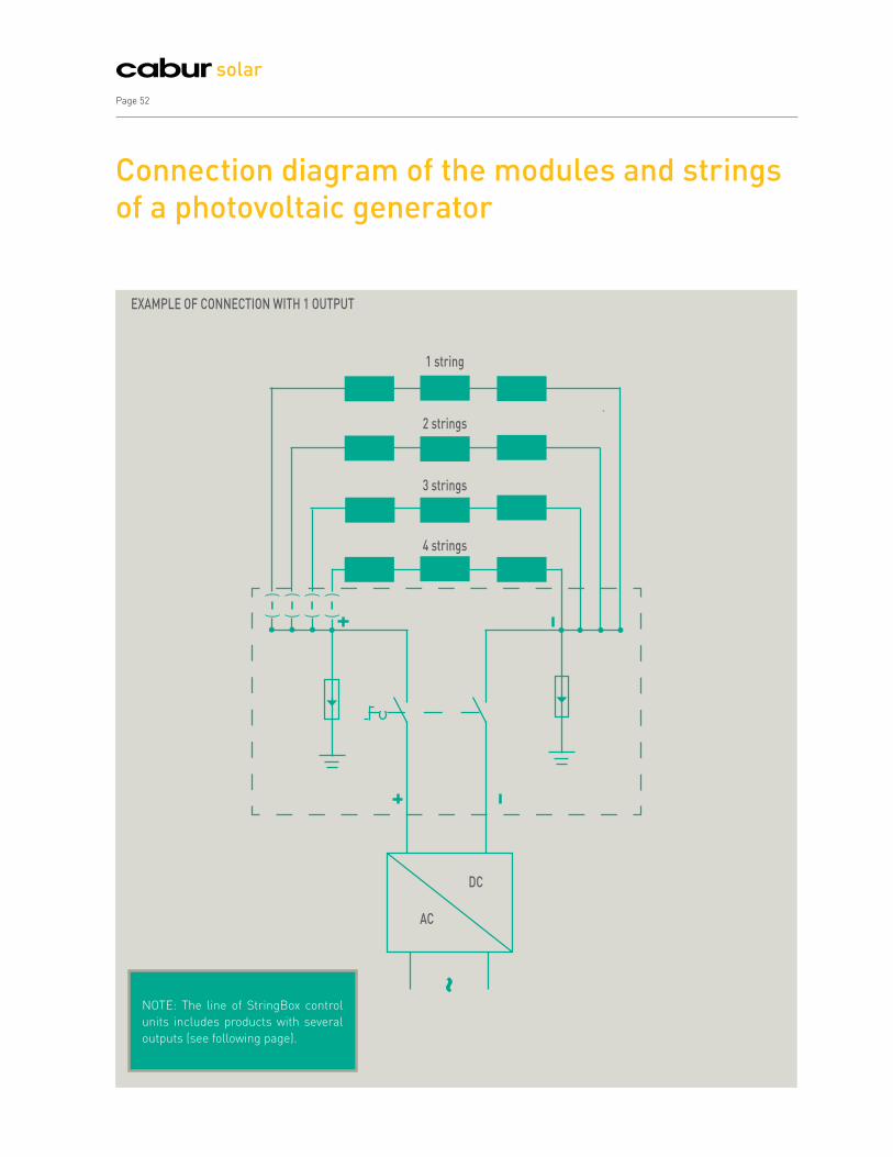
NOTE: The line of StringBox control
units includes products with several
outputs (see following page).
Connection diagram of the modules and strings of a photovoltaic generator
DC
1 string
2 strings
EXAMPLE OF CONNECTION WITH 1 OUTPUT
3 strings
4 strings
~
AC
Page 52
solar

Cabur Solar Page 53
StringBox connection panels for photovoltaic panel stringsThe connection panels of the StringBox series are designed
and constructed according to Standard CEI 82-25.
This is a real solution for the various needs of this sector,
which takes into due consideration the need for customised
products.
The boxes are available in 1, 2, 3, 4, 6 and 8 strings versions
and include all components necessary for protection and for
parallel connection of the strings of solar panels.
All components are pre-wired with a special solar wire,
therefore in the case of electrical panels with connector input,
the Customer must simply connect the same and provide for
earth wiring and output towards the inverter, with considerable
saving both in the management of the components and in
installation.
The illustration below shows an example of the components
that can be inserted into the panel.
Boxes for external use in
polycarbonate with high UV
resistance, with protection degree
of IP 66.
Connectors for special solar
wires with protection degree
IP67, equipped with mechanical
blocking device to avoid
accidental unhooking.
Fuse holders 10.3 x 38 approved
UL 1,000 VDC; the fuse holders
are contained in the 4, 6 and 8
string boxes and can switch the
strings off in the case of fault,
string short circuit or short circuit
on the connections; usually the 2
and 3 string panels do not have
fuse holders because the max
current generated by one or two
strings would not be sufficient to
cause a fuse to trip in the case of
a fault in a string; the fuses must
be chosen and ordered by the
customer according to the value
of the string current.
Surge protection devices: 20 kA (8/20),
Ures ≤ 1.5 kV, available in voltages 500
VDC, 600 VDC, 800 VDC, and 1,000 VDC
for better coordination with the voltage
effectively generated by the system.
DC-21A disconnector: Approved UL at
1 kVDC, available for nominal currents
of 40 A and 63 A; as requested by
CEI 82-25, it is approved as isolator
switch under charge and allows for
disconnecting the voltage generated
by the strings for the execution of
interventions downstream of the
SolarBox panel in total safety.
Blocking diodes to prevent the
current of fully efficient strings
from circulating in "shaded" or
faulty strings, or strings whose
generation capacity is reduced
and which are available as
standard versions. The diodes
are fitted on aluminium plates to
dissipate the heat generated by
the current which runs through
them. WARNING: CEI 82-25
recommends that the blocking
diode be used for boxes with 3 or
more strings.
Advantages of the StringBox series
1. Fast installation: components are already wired,
able to connect using extractable connectors
2. Standardised product, in conformance with the
regulations in effect: ideal to minimize design and
inspection times and costs
3. Quality components in conformance with the
regulations in effect
4. Large product range able to satisfy a wide range of
needs
5. Box assembly completed and inspected by qualified
personnel
The range is divided into three series
Standard: the most commonly used models, which
include panels for ungrounded floating systems with
both positive and negative, and for negative ground
systems; usually always in stock (see pages 54 and 55)
Special: models which satisfy less common needs;
including panels with grounded positive pole and panels
with modifications which can be derived from standard
panels; for codes and sales conditions, please contact
our sales network
Custom: string boxes for specific needs, which Cabur
constructs at the Customer's request, not included in
the above categories. For information, please contact
our sales network

Page 54
solar
Standard StringBox panelswith fuses at both poles for floating systemsPanels for strings with fuse holders on both poles, suitable
for systems with neither pole earthed; also usable in systems
with one earthed pole, inserting small short-circuit protection
cylinders instead of the fuses of the common earthed poles.
Produced in versions with or without diodes, string input
by means of solar connectors (models KX04PM4060 and
KX04PF4060) for wires of 4 mm² and 6 mm². The fuse holders
do not have fuses, which must be chosen and ordered by
the customer according to the string current (see page 88).
Special versions can be constructed on request, with string
input through cable glands and/or 500 VDC limit devices. All
the StringBox panels are supplied in packs of 1 piece.
Code Panel rated U/I N° of StringsUCmax /UDC STC
Limit deviceDimensions
(LxHxW)
ISB02HDCA06 40A 480Vdc 2 600/1,200V 300x300x180
ISB02HDCA08 40A 690Vdc 2 800/1,600V 300x300x180
ISB02HDCA10 40A 690Vdc 2 1,000/2,000V 300x300x180
ISB03HDCA06 40A 480Vdc 3 600/1,200V 300x300x180
ISB03HDCA08 40A 690Vdc 3 800/1,600V 300x300x180
ISB03HDCA10 40A 690Vdc 3 1,000/2,000V 300x300x180
ISB04HDCA06 40A 480Vdc 4 600/1,200V 450x450x180
ISB04HDCA08 40A 690Vdc 4 800/1,600V 450x450x180
ISB04HDCA10 40A 690Vdc 4 1,000/2,000V 450x450x180
ISB06HDCB06 63A 690Vdc 6 600/1,200V 540x360x180
ISB06HDCB08 63A 690Vdc 6 800/1,600V 540x360x180
ISB06HDCB10 63A 690Vdc 6 1,000/2,000V 540x360x180
ISB08HDCB06 63A 690Vdc 8 600/1,200V 540x540x180
ISB08HDCB08 63A 690Vdc 8 800/1,600V 540x540x180
ISB08HDCB10 63A 690Vdc 8 1,000/2,000V 540x540x180
Code Panel rated U/I N° of StringsUCmax /UDC STC
Limit deviceDimensions
(LxHxW)
ISB01HXCA06 40A 480Vdc 1 600/1,200V 300x300x180
ISB01HXCA08 40A 690Vdc 1 800/1,600V 300x300x180
ISB01HXCA10 40A 690Vdc 1 1,000/2,000V 300x300x180
ISB02HXCA06 40A 480Vdc 2 600/1,200V 300x300x180
ISB02HXCA08 40A 690Vdc 2 800/1,600V 300x300x180
ISB02HXCA10 40A 690Vdc 2 1,000/2,000V 300x300x180
ISB03HXCA06 40A 480Vdc 3 600/1,200V 300x300x180
ISB03HXCA08 40A 690Vdc 3 800/1,600V 300x300x180
ISB03HXCA10 40A 690Vdc 3 1,000/2,000V 300x300x180
ISB04HXCA06 40A 480Vdc 4 600/1,200V 450x450x180
ISB04HXCA08 40A 690Vdc 4 800/1,600V 450x450x180
ISB04HXCA10 40A 690Vdc 4 1,000/2,000V 450x450x180
ISB06HXCB06 63A 690Vdc 6 600/1,200V 540x360x180
ISB06HXCB08 63A 690Vdc 6 800/1,600V 540x360x180
ISB06HXCB10 63A 690Vdc 6 1,000/2,000V 540x360x180
ISB08HXCB06 63A 690Vdc 8 600/1,200V 540x360x180
ISB08HXCB08 63A 690Vdc 8 800/1,600V 540x360x180
ISB08HXCB10 63A 690Vdc 8 1,000/2,000V 540x360x180
Version with blocking diode
Version without diode
The range could vary and be expanded, even in the very near future, to effectively answer the needs of a rapidly evolving market; it is therefore advisable to check on possible updating at the website www.cabur.eu.
Note: the limit device (or discharge device) must have a size such that it has a Uc voltage of at least 25% more than the Uoc (string voltage)
Example in photo and diagram of model
ISB04HDCA06
Example in photo and diagram of model
ISB04HXCA06

Cabur Solar Page 55
The range could vary and be expanded, even in the very near future, to effectively answer the needs of a rapidly evolving market; it is therefore advisable to check on possible updating at the website www.cabur.eu.
Note: the limit device (or discharge device) must have a size such that it has a Uc voltage of at least 25% more than the Uoc (string voltage)
Standard StringBox panelswith fuse on the positive pole for positive-grounded systemsString panels with fuse holder on positive pole suitable for
systems with earthed negative pole. Produced in versions with
or without diodes, string input by means of solar connectors
(models KX04PM4060 and KX04PF4060) for wires of 4 mm²
and 6 mm². The fuse holders do not have fuses, which must be
chosen and ordered by the customer according to the string
current (see page 88). Special versions can be constructed
on request, with string input through cable glands and/or 500
VDC limit devices.
Code Panel rated U/I N° of StringsUCmax /UDC STC
Limit deviceDimensions
(LxHxW)
ISB01FDCA06 40A 480Vdc 1 600/1,200V 300x300x180
ISB01FDCA08 40A 690Vdc 1 800/1,600V 300x300x180
ISB01FDCA10 40A 690Vdc 1 1,000/2,000V 300x300x180
ISB02FDCA06 40A 480Vdc 2 600/1,200V 300x300x180
ISB02FDCA08 40A 690Vdc 2 800/1,600V 300x300x180
ISB02FDCA10 40A 690Vdc 2 1,000/2,000V 300x300x180
ISB03FDCA06 40A 480Vdc 3 600/1,200V 300x300x180
ISB03FDCA08 40A 690Vdc 3 800/1,600V 300x300x180
ISB03FDCA10 40A 690Vdc 3 1,000/2,000V 300x300x180
ISB04FDCA06 40A 480Vdc 4 600/1,200V 450x450x180
ISB04FDCA08 40A 690Vdc 4 800/1,600V 450x450x180
ISB04FDCA10 40A 690Vdc 4 1,000/2,000V 450x450x180
ISB06FDCB06 63A 690Vdc 6 600/1,200V 540x360x180
ISB06FDCB08 63A 690Vdc 6 800/1,600V 540x360x180
ISB06FDCB10 63A 690Vdc 6 1,000/2,000V 540x360x180
ISB08FDCB06 63A 690Vdc 8 600/1,200V 540x540x180
ISB08FDCB08 63A 690Vdc 8 800/1,600V 540x540x180
ISB08FDCB10 63A 690Vdc 8 1,000/2,000V 540x540x180
Code Panel rated U/I N° of StringsUCmax /UDC STC
Limit deviceDimensions
(LxHxW)
ISB01FXCA06 40A 480Vdc 1 600/1,200V 300x300x180
ISB01FXCA08 40A 690Vdc 1 800/1,600V 300x300x180
ISB01FXCA10 40A 690Vdc 1 1,000/2,000V 300x300x180
ISB02FXCA06 40A 480Vdc 2 600/1,200V 300x300x180
ISB02FXCA08 40A 690Vdc 2 800/1,600V 300x300x180
ISB02FXCA10 40A 690Vdc 2 1,000/2,000V 300x300x180
ISB03FXCA06 40A 480Vdc 3 600/1,200V 300x300x180
ISB03FXCA08 40A 690Vdc 3 800/1,600V 300x300x180
ISB03FXCA10 40A 690Vdc 3 1,000/2,000V 300x300x180
ISB04FXCA06 40A 480Vdc 4 600/1,200V 450x450x180
ISB04FXCA08 40A 690Vdc 4 800/1,600V 450x450x180
ISB04FXCA10 40A 690Vdc 4 1,000/2,000V 450x450x180
ISB06FXCB06 63A 690Vdc 6 600/1,200V 540x360x180
ISB06FXCB08 63A 690Vdc 6 800/1,600V 540x360x180
ISB06FXCB10 63A 690Vdc 6 1,000/2,000V 540x360x180
ISB08FXCB06 63A 690Vdc 8 600/1,200V 540x360x180
ISB08FXCB08 63A 690Vdc 8 800/1,600V 540x360x180
ISB08FXCB10 63A 690Vdc 8 1,000/2,000V 540x360x180
Version with blocking diode
Version without diode
Example in photo and diagram of model
ISB04FDCA06
Example in photo and diagram of model
ISB04FXCA06

Page 56
solar
StringBox control unitsApplications and advantages
Applications Advantages
Suitable for civil systems
Suitable both for inside and outside
Suitable for medium and small power installations
Degree of protection IP65
1,000 VDC voltage
Multiple ouputs for connections to latest generation
inverters
Appearance: ideal design for installation in civil
systems
High reliability
Toughness
The models are differentiated by the number of inputs, number of outputs, number of fuse
boxes, SPD models and therefore the size of the box. Model are also available with release coil.

Cabur Solar Page 57
Solar panel
Small DC string box
Inverter
DC control unitDC surge protection device
Junction boxes
Network interface
Installation diagram of a photovoltaic system connected to the network
The CaburSolar control units have IP65 level of
protection and are pleasing to the eye making them easy
to integrate into any environment. They are therefore
the ideal solution for creating string boxes in domestic
and small service industry applications.
The connection panels of the StringBox series are
designed and constructed according to the Photovoltaic
Guide CEI 82-25. This is a real solution for the various
needs of this sector, which takes into due consideration
the need for customised products.
In most cases the photovoltaic systems are generally
placed in very exposed positions (fields, roofs, etc.) and
therefore are subject to atmospheric phenomena and
can be damaged due to surges generated by lightning
in the installations.
The control units of the Cabur StringBox Series are
always equipped with surge protectors (SPD) on every
polarity to earth in accordance with the risk analysis
done based on standard EN 62305-2.

StringBox control unitsTechnical features
Models are available with
release coil to switch-off
remotely in conformity with
the new regulations provided
by the guide CEI 82-25 for
public access locations with
risk of fire.
A 1,000 VDC disconnector to be able to intervene in complete
safety
A 600 or 1,000 VDC surge protection device in Y configuration
Terminal block with screws for the connections (inverter,
strings,...)
Connectors for input Cabur Solar Line 4 type strings
Cable glands for outputs to inverter
The following are available:
Models with fuse boxes on positive or on positive-negative
pole
Accessories: door key and lock
Multiple output
Release coil to switch-off remotely in conformity with the
new regulations provided by the guide CEI 82-25 for public
access locations with risk of fire
The control units differ by number of inputs, number of outputs,
by SPD models and by number of fuses and consequently by
size of box
The StringBox series control units are made with the
following components:
Page 58
solar

StringBox control unitsTechnical features
Cabur Solar Page 59
Wiring diagram example for 1 string input, 1 output ISB0101FXCAxx
Container IP65
Dimensions in
Modules: 9
Dimensions in mm:
200x238x111
Container IP65
Dimensions in
Modules: 12
Dimensions in mm:
295x333x129
Wiring diagram example for 2 string input, 1 output ISB0201FXCAxx
Container IP65
Dimensions in
Modules: 18
Dimensions in mm:
403x333x129
Wiring diagram example for 2 string input, 2 output ISB0202FXCAxx
Container IP65
Dimensions in
Modules: 12
Dimensions in mm:
295x333x129
Wiring diagram example for 3 string input, 1 output ISB0301FXCAxx

StringBox control unitsTechnical features
Page 60
solar
Wiring diagram example for 3 string input, 2 output ISB0302FXCAxx
Container IP65
Dimensions in
Modules: 18
Dimensions in mm:
403x333x129
Wiring diagram example for 4 string input, 1 output ISB0401FXCAxx
Container IP65
Dimensions in
Modules: 18
Dimensions in mm:
403x333x129
Wiring diagram example for 4 string input, 2 output ISB0402FXCAxx
Container IP65
Dimensions in
Modules: 12x2
Dimensions in mm:
295x458x129

Models are available without fuses. Contact the Cabur sales network for more information.
StringBox control unitsSelection table of the models without release coil
Cabur Solar Page 61
Code Inputs OutputsFuse holder UC voltage
discharger
Disconnectors
(1,000 VDC)Release coil
Dimensions
in modules
Dimensions
in mm
(LxHxW)Positive Negative
ISB0101FXCA06 1 1 x 600 V 20 A - 9 200x238x111
ISB0101FXCA10 1 1 x 1,000 V 20 A - 9 200x238x111
ISB0101HXCA06 1 1 x x 600 V 20 A - 9 200x238x111
ISB0101HXCA10 1 1 x x 1,000 V 20 A - 9 200x238x111
ISB0201FXCA06 2 1 x 600 V 20 A - 12 295x333x129
ISB0201FXCA10 2 1 x 1,000 V 20 A - 12 295x333x129
ISB0201HXCA06 2 1 x x 600 V 20 A - 12 295x333x129
ISB0201HXCA10 2 1 x x 1,000 V 20 A - 12 295x333x129
ISB0202FXCA06 2 2 x 600 V 20 A - 18 403x333x129
ISB0202FXCA10 2 2 x 1,000 V 20 A - 18 403x333x129
ISB0202HXCA06 2 2 x x 600 V 20 A - 18 403x333x129
ISB0202HXCA10 2 2 x x 1,000 V 20 A - 18 403x333x129
ISB0301FXCA06 3 1 x 600 V 32 A - 12 295x333x129
ISB0301FXCA10 3 1 x 1,000 V 32 A - 12 295x333x129
ISB0301HXCA06 3 1 x x 600 V 32 A - 18 403x333x129
ISB0301HXCA10 3 1 x x 1,000 V 32 A - 18 403x333x129
ISB0302FXCA06 3 2 x 600 V 32 A - 18 403x333x129
ISB0302FXCA10 3 2 x 1,000 V 32 A - 18 403x333x129
ISB0302HXCA06 3 2 x x 600 V 32 A - 12x2 295x458x129
ISB0302HXCA10 3 2 x x 1,000 V 32 A - 12x2 295x458x129
ISB0303FXCA06 3 3 x 600 V 20 A - 12x2 295x458x129
ISB0303FXCA10 3 3 x 1,000 V 20 A - 12x2 295x458x129
ISB0401FXCA06 4 1 x 600 V 32 A - 18 403x333x129
ISB0401FXCA10 4 1 x 1,000 V 32 A - 18 403x333x129
ISB0401HXCA06 4 1 x x 600 V 32 A - 18 403x333x129
ISB0401HXCA10 4 1 x x 1,000 V 32 A - 18 403x333x129
ISB0402FXCA06 4 2 x 600 V 32 A - 12x2 295x458x129
ISB0402FXCA10 4 2 x 1,000 V 32 A - 12x2 295x458x129
ISB0402HXCA06 4 2 x x 600 V 32 A - 12x2 295x458x129
ISB0402HXCA10 4 2 x x 1,000 V 32 A - 12x2 295x458x129
All the StringBox control panels are supplied in packs of 1 piece.

StringBox control unitsSelection table of models with release coil in accordance with the Italian Fire and Rescue Services Circular
Models are available without fuses. Contact the Cabur sales network for more information.
Page 62
solar
Code Inputs OutputsFuse holder UC voltage
discharger
Disconnectors
(1,000 VDC)Release coil
Dimensions
in modules
Dimensions
in mm
(LxHxW)Positive Negative
ISA0101FXCA06 1 1 x 600 V 20 A x 9 200x238x111
ISA0101FXCA10 1 1 x 1,000 V 20 A x 9 200x238x111
ISA0101HXCA06 1 1 x x 600 V 20 A x 12 295x333x129
ISA0101HXCA10 1 1 x x 1,000 V 20 A x 12 295x333x129
ISA0201FXCA06 2 1 x 600 V 32 A x 12 295x333x129
ISA0201FXCA10 2 1 x 1,000 V 32 A x 12 295x333x129
ISA0201HXCA06 2 1 x x 600 V 32 A x 12 295x333x129
ISA0201HXCA10 2 1 x x 1,000 V 32 A x 12 295x333x129
ISA0202FXCA06 2 2 x 600 V 20 A x 18 403x333x129
ISA0202FXCA10 2 2 x 1,000 V 20 A x 18 403x333x129
ISA0202HXCA06 2 2 x x 600 V 20 A x 18 403x333x129
ISA0202HXCA10 2 2 x x 1,000 V 20 A x 18 403x333x129
ISA0301FXCA06 3 1 x 600 V 32 A x 12 295x333x129
ISA0301FXCA10 3 1 x 1,000 V 32 A x 12 295x333x129
ISA0301HXCA06 3 1 x x 600 V 32 A x 18 295x333x129
ISA0301HXCA10 3 1 x x 1,000 V 32 A x 18 295x333x129
ISA0302FXCA06 3 2 x 600 V 32 A x 12x2 295x458x129
ISA0302FXCA10 3 2 x 1,000 V 32 A x 12x2 295x458x129
ISA0302HXCA06 3 2 x x 600 V 32 A x 12x2 295x458x129
ISA0302HXCA10 3 2 x x 1,000 V 32 A x 12x2 295x458x129
ISA0401FXCA06 4 1 x 600 V 32 A x 18 403x333x129
ISA0401FXCA10 4 1 x 1,000 V 32 A x 18 403x333x129
ISA0401HXCA06 4 1 x x 600 V 32 A x 18 403x333x129
ISA0401HXCA10 4 1 x x 1,000 V 32 A x 18 403x333x129
ISA0402FXCA06 4 2 x 600 V 32 A x 12x2 295x458x129
ISA0402FXCA10 4 2 x 1,000 V 32 A x 12x2 295x458x129
ISA0402HXCA06 4 2 x x 600 V 32 A x 12x2 295x458x129
ISA0402HXCA10 4 2 x x 1,000 V 32 A x 12x2 295x458x129
All the StringBox control panels are supplied in packs of 1 piece.
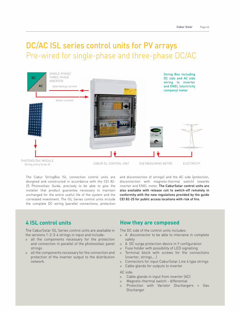
Cabur Solar Page 63
String Box including
DC side and AC side
wiring to inverter
and ENEL (electricity
company) meter
The Cabur StringBox ISL connection control units are
designed and constructed in accordance with the CEI 82-
25 Photovoltaic Guide, precisely to be able to give the
installer that product guarantee necessary to maintain
unchanged for the entire useful life of the system and the
correlated investment. The ISL Series control units include
the complete DC wiring (parallel connections, protection
and disconnection of strings) and the AC side (protection,
disconnection with magneto-thermal switch) towards
inverter and ENEL meter. The CaburSolar control units are
also available with release coil to switch-off remotely in
conformity with the new regulations provided by the guide
CEI 82-25 for public access locations with risk of fire.
DC/AC ISL series control units for PV arrays Pre-wired for single-phase and three-phase DC/AC
DC
AC
PHOTOVOLTAIC MODULE
String entry (max 4) CABUR ISL CONTROL UNIT
direct current
alternating current
SINGLE-PHASE/
THREE-PHASE
INVERTER
GSE MEASURING METER ELECTRICITY
The CaburSolar ISL Series control units are available in
the versions 1-2-3-4 strings in input and include:
all the components necessary for the protection
and connection in parallel of the photovoltaic panel
strings
all the components necessary for the connection and
protection of the inverter output to the distribution
network.
The DC side of the control units includes:
A disconnector to be able to intervene in complete
safety
A DC surge protection device in Y configuration
Fuse holder with possibility of LED signalling
Terminal block with screws for the connections
(inverter, strings,...)
Connectors for input CaburSolar Line 4 type strings
Cable glands for outputs to inverter
AC side:
Cable glands in input from inverter (AC)
Magneto-thermal switch - differential
Protection with Varistor Dischargers + Gas
Discharger
4 ISL control units How they are composed

Page 64
solar
Control unit codes with fuses only on positive
Control unit codes with fuses only on positive and negative
DC/AC ISL series control units for PV arrays 1 output control unit technical tables
ISL0101FXCAXX ISL0201FXCAXX ISL0301FXCAXX ISL0401FXCAXX
Final Code XX = 06 10 06 10 06 10 06 10
Number of input strings 1 2 3 4
Maximum voltage: 1,000 VDC 1,000 VDC 1,000 VDC 1,000 VDC
Maximum string current 20 A 15 A 10 A 8 A
DC Uc discharger (volts) 600 1,000 600 1,000 600 1,000 600 1,000
Discharger in AC 275 275 440 440
Magneto-thermal carrying capacity 16 Single-phase 32 Single-phase 32 Three-phase 32 Three-phase
Degree of protection (A) IP65 IP65 IP65 IP65
Input connectors Cabur Line 4 Cabur Line 4 Cabur Line 4 Cabur Line 4
Input wires section 4-6 mm2 4-6 mm2 4-6 mm2 4-6 mm2
Dimensions 295x458x129 295x458x129 295x458x129 295x458x129
Conformity standards/guides CEI 82-25 CEI 82-25 CEI 82-25 CEI 82-25
Recommended for systems ‹ 3kW ‹ 6kW ‹ 10kW ‹ 20kW
Quantity per pack 1 1 1 1
ISL0101HXCAXX ISL0201HXCAXX ISL0301HXCAXX ISL0401HXCAXX
Final Code XX = 06 10 06 10 06 10 06 10
Number of input strings 1 2 3 4
Maximum voltage: 1,000 VDC 1,000 VDC 1,000 VDC 1,000 VDC
Maximum string current 20 A 15 A 10 A 8 A
DC Uc discharger (volts) 600 1,000 600 1,000 600 1,000 600 1,000
Discharger in AC 275 275 440 440
Magneto-thermal carrying capacity 16 Single-phase 32 Single-phase 32 Three-phase 32 Three-phase
Degree of protection (A) IP65 IP65 IP65 IP65
Input connectors Cabur Line 4 Cabur Line 4 Cabur Line 4 Cabur Line 4
Input wires section 4-6 mm2 4-6 mm2 4-6 mm2 4-6 mm2
Dimensions 295x458x129 295x458x129 295x458x129 295x458x129
Conformity standards/guides CEI 82-25 CEI 82-25 CEI 82-25 CEI 82-25
Recommended for systems ‹ 3kW ‹ 6kW ‹ 10kW ‹ 20kW
Quantity per pack 1 1 1 1
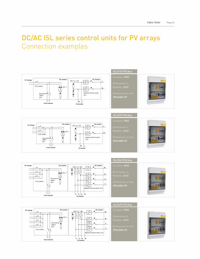
Cabur Solar Page 65
DC/AC ISL series control units for PV arrays Connection examples
ISL0101FXCAxx
PV strings DC section AC section
Magneto-thermal switch
To inverterFrom inverter
Disconnector
Fuse holders
Container IP65
Dimensions in
Modules: 2x12
Dimensions in mm:
295x458x129
ISL0301FXCAxx
PV strings DC section AC section
From inverterTo inverter
Disconnector
Fuse holders
Magneto-thermal switch
Container IP65
Dimensions in
Modules: 2x12
Dimensions in mm:
295x458x129
ISL0201FXCAxx
PV stringsDC section AC section
Magneto-thermal switch
To inverterFrom inverter
Disconnector
Fuse holders
Container IP65
Dimensions in
Modules: 2x12
Dimensions in mm:
295x458x129
ISL0401FXCAxx
PV strings DC section AC section
From inverter To inverter
Disconnector
Fuse holders
Magneto-thermal switch
Container IP65
Dimensions in
Modules: 2x12
Dimensions in mm:
295x458x129

Page 66
solar
The connection panels of the E-Box series are designed and
constructed according to the Photovoltaic Guide CEI 82-25.
This is a real solution for the various needs of this sector,
which takes into due consideration the need for customised
products. The Cabur line in fact includes String Boxes, fuses
and fuse holders, surge protection devices, control units and
sleeves suitable for use outside, all specially designed for this
type of application.
The E-Box panels are available in the 4, 8 and 16 string
versions and include all the components necessary to connect
strings in parallel, to protect the system, to disconnect and
transmit the characteristic data of the panel, such as voltage
and current of each string.
The Cabur E-Box line parallel panel therefore uses its own
inner instruments capable of measuring the currents flowing
in the photovoltaic strings, the string parallel voltage and at the
same time detect the operating status of input signals relative
to the status of the protection and alarm devices installed in
the panels. The measurements of the string current are done
with modules using amperometric Hall effect sensors which
guarantee a high degree of insulation with the control and
measurement unit.
The string box has at output an RS485 serial port used to
transfer the instantaneous data from the panel to a possible
remote PC. The serial transmission on RS485 twisted pair
with protocol Modbus RTU allows a network of interconnected
modules (slaves) and a remote PC unit (master) which acts as
data logger to be constructed. By operating on bridges, it is
possible to direct every field module in order to construct the
multi-slave network.
E-BoxString and monitoring boxes with electronics for monitoring
Combiner boxes with integrated electronics for monitoring
and measure power/energy

Cabur Solar Page 67
E-BoxConnection Diagram
AB
C
D
V Supply RS 485 ModBus RTU
Measurement string currents
CT Modules
CONTROL ELECTRONICS
( —
)
( —
)
( —
)
( —
)
( —
)
( —
)
( —
)
( —
)
( —
)
( —
)
( —
)
( —
)
( —
)
( —
)
( —
)
( —
)
AB
C
SPD
Group
Output for inverter
INPUT NEGATIVE STRINGSINPUT POSITIVE STRINGS
D
A disconnector to be able to intervene in complete safety
A DC Cabur surge protection device in Y configuration
Fuse holder 10x38 for voltages up to 1,000 V
Cabur Series CBC and GPA terminal block with screws for
the connections (inverter, strings,...)
Connectors for input Cabur Solar Line 4 type strings
Cable glands for outputs to inverter
Control unit with microprocessor for data transmission
Current transformers (CT) modules with Hall sensors for
measuring current
Voltage transformer (VT) module for measuring voltage
E-Box is composed of:
Switch disconnector
Fuse holders

Page 68
solar
STANDARD E-BOX CODES
TECHNICAL CHARACTERISTICSfor systems with 4 strings
at inputfor systems with 8 strings
at inputfor systems with 16
strings at input
With fuse holder on positive ISE04FXCD10 ISE08FXCD10 ISE16FXCE10
With fuse holder on positive and negative ISE04HXCD10 ISE08HXCD10 ISE16HXCE10
No. inputs Number of input strings 4 8 16
No. outputs Number of output strings 1 1 1
Voltage Maximum operating voltage under load 800 V 800 V 1,000 V
Current
Maximum string currentMaximum parallel currentMaximum operating current under load
10 A40 A40 A
10 A80 A80 A
10 A160 A120 A
SPDContinuous current UC dischargerProtection impulsive voltage UP
1,000 V3,000 V
1,000 V3,000 V
1,000 V3,000 V
Protection Degree of protection water IP65 IP65 IP65
Connection
Connectors input positive stringConnectors input negative stringCable glands in output strings parallelCable glands in output connection to earth
IS24111IS14110
PG21PG9
IS24111IS14110
PG21PG9
IS24111IS14110
PG21PG9
Wire sectionWire section input stringsWire section output strings
4-6 mm2
25-95 mm2
4-6 mm2
25-95 mm2
4-6 mm2
25-95 mm2
Oper. Cond. Minimum operating temp. control unitMaximum operating temp.
-10° C+65° C
-10° C+65° C
-10° C+65° C
Hall sensorsNumber of cards with Hall sensorsHall sensors used
14
28
416
Control Unit Number of current reading channels 8 8 16
Transm. DataSerial typeCommunication protocol
RS485Modbus RTU
RS485Modbus RTU
RS485Modbus RTU
Dimensions Outside dimensions 540x540x127 540x540x127 540x540x127
Standards Conformity standards/guidesCEI 82-25CEI 17-13
CEI 82-25CEI 17-13
CEI 82-25CEI 17-13
Q.ty / pack 1 1 1
E-BoxCodes and technical characteristics
NOTE: It is possible to request custom solutions by contacting the Cabur sales network.
Designed and built in accordance with
the Photovoltaic Guide CEI 82-25
Provided with an RS485 serial port at
output used to transfer the instantaneous
data from the panel to a possible remote
PC
Protocol of transmission: Modbus RTU
Versions available for systems with 4, 8,
16 strings at input

Cabur Solar Page 69
E-BoxGeneral features
Operating conditions
System of communication
Input and output lines String Box
To guarantee an optimal measurement of the panel, we
recommend installing in an environment with minimum
temperature -10 °C and maximum temperature 65 °C
with a relative humidity of between 5% and 95% without
condensation.
The String Box has in the control unit a serial port on standard
physical RS485.
The serial port allows the instantaneous measures of the
data coming from the CT modules to be sent to a remote unit
such as a PC. The serial port should be used if a connection
network between several Cabur field panels is being created.
The RS485 communication line between the various panels
or between the panels and the PC should preferably be done
with twisted and screened wire in order to reduce problems
from electromagnetic interference. The maximum connection
distance between the first and last network device must not
exceed 1200 metres. We recommend using screened wire
in environments affected by electromagnetic noise. The
protection screen must be connected to one of the two earthed
points between signal arrival and departure. We recommend
no connecting the GND end of reference of the RS485 line to
the earthed end or to the protection screen in order to avoid
abnormal currents from circulating. It is recommended that
the devices be connected in input and output mode rather
than creating connections with branches. Never use a star
connection. It is preferable to connect the parallel devices
in enter-exit mode rather than creating a principal bus with
numerous branches.
The communication protocol use by the string boxes is the
Modbus type with RTU mode. Every unit can be identified by
a single address. This address can be set through bridges
present on the chart of the electronic module.
Positive photovoltaic lines max 16 - input
Negative photovoltaic lines max 16 - input
Positive output photovoltaic line per inverter - output
Negative output photovoltaic line per inverter - output
Electronic Supply line Control Unit/Power Supply
VAC 230 PHASE - input
Electronic Supply line Control Unit/Power Supply
VAC 230 NEUTRAL - input
Line RS485 data RX modbus RTU - input
Line RS485 data TX modbus RTU - output
Rs485
Rs485Rs485
EXCELLENT NO NOT RECOMMENDED
Types of connection with RS485 twisted pair

E-BoxPanel for parallel connections with monitoring electronics
Page 70
solar
photovoltaic field strings
photovoltaic field strings
photovoltaic field strings
inverter
inverter
calculator of supervision and
display system capability
Applications
web
Rs485 ETH/TCPIP

Cabur Solar Page 71
E-Box componentsControl and measurement control unit (code ISPECU1)
Does not require configuration in terms of the voltage and/
or current measurement
Input of power supply with direct current from +15 to 28 VDC
max
Max input of voltage: 1,000 VDC with connection to the
module ISPVLT1
Input current: 25A (with Hall effect sensors) with connection
to the module ISAMP4
Protocol of transmission: Modbus RTU
2 digital inputs
1 serial port RS485
Quantity per pack: 1

Page 72
solar
Control unit ISPECU1Technical features
The electronic control unit has a power supply input of direct
current from +15 V to 28 DC max.
Voltage in DC: 24 DC +/- 10%
Consumption in DC: 250 mA max
Reference: ModBus RTU
Speed of transmission: 19,200 baud
Length datum: 8bit
Parity: none
Stop bit: 1bit
The control unit uses the Modbus RTU transmission protocol
to send the data. Modbus is the most widespread serial
communication protocol between industrial electronic
devices. Modbus permits the communication between
various devices connected to the same network, it is used to
connect a supervisor computer with a remote terminal unit
(RTU) in the supervision control and data acquisition systems
(SCADA).
The control unit has 2 clean contact digital inputs and a
common terminal with 24 DC output voltage for the detection
of the logic status of the protection systems or other command
devices installed in the photovoltaic field.
The control unit continuously controls in real time the logic
status (open or closed) of the digital inputs and, through the
RS485 serial port connected to PC transmits the information
to the supervision software. The use of these digital inputs is
optional and does not affect in any way the remaining features
of the control unit device.
The control unit has 1 RS485 serial to transfer the
instantaneous measurements to PC. The RS485 connection
line must be done using a twisted and screen communication
wire (minimum 3 conductors) preferably with the following
characteristics:
flexible
category 5 or greater
4 conductors Ø 0.5 mm2
with screen
The maximum connection distance between the first and last
device inserted on the RS485 line must not exceed 1,200 metres.
Power supply
Consumption
System of communication
Connection digital inputs
Connection to PC through serial port (salve)
The communication protocol used by the control units is the
MODBUS type with RTU mode.
The RS485 serial port is used to connect the unit of
measurement to a continuous monitoring system. It is
necessary to identify every single unit through a unique and
unambiguous identification address.
The measurement control unit does not require any
configuration relative to the measurement of voltage and/
or current since the flow meters are already set and
defined. Instead every single device must be configured for
communication to PC and for the connection in multi-slave
cascade mode.
Configuration
Communication protocol
For short connection distances (‹ 5 metres) the wire used
does not have to have a screen. For greater distances or areas
particularly affected by electrical and electromagnetic noise
and disturbances, it is instead necessary to use screened
wires. The protection screen should be connected to an
earthed terminal on one of the ends of the RS485 line in
order to discharge to earth any disturbances induced. Do not
connect the GND end of reference of the RS485 line to the
earthed terminal or to the protection screen in order to avoid
abnormal currents from circulating to different potentials.

Cabur Solar Page 73
ISPECU1 control unitTypes of connection with RS485 twisted pair
The control unit transfers the information to PC using the
communication protocol MODBUS with RTU mode. Every
message is composed of 8 codes containing 2 hexadecimal
characters of 4 bytes.
The format of every byte in RTU mode is the following:
The following table lists the codes of the MODBUS addresses
relative to the units (slaves).
ModBus protocol
ModBus registers
Code
8 bit binaries in hexadecimal from 0 to 9 A-F, 2 hexadecimal characters contained in every 8 bit field of the message
Bit per byte 8 bit
Check error field CRC (Cyclical Redundancy Check) type
Parameter Abbreviation ModBus address Unit of measure
Current of string 1 I1 0x0000 A x 100
Current of string 2 I2 0x0001 A x 100
Current of string 3 I3 0x0002 A x 100
Current of string 4 I4 0x0003 A x 100
Current of string 5 I5 0x0004 A x 100
Current of string 6 I6 0x0005 A x 100
Current of string 7 I7 0x0006 A x 100
Current of string 8 I8 0x0007 A x 100
Analogue 0 A0 0x0009 V x 100
Analogue 1 A1 0x000A V x 100
Analogue 2 A2 0x000B V x 100
Analogue 3 A3 0x000C V x 100
Digital 0 - 1 D0 D1 0x000D -
Temperature T 0x000E °C
Power supply voltage Va 0x000F V
String voltage V1 0x0010 V
Peripheral address Ad 0x0011 -
Cabur reserves the right to change the technical data listed in the table, without advance notice, for production needs or development of
improvements. Please refer to the Cabur technical-commercial organisation for updates on the technical data of the product.

Page 74
solar
E-Box componentsSingle-phase switching power supply Series DOMOTIC POWER (code XCSD30C)
158 mm
45 mm
Conn 1
The single-phase switching power supply for DIN rail with
30W power, ideal for applications in civil and industrial
automation. Standard modular DIN measurements for
installations in control units. High output and a contained
operating temperature to promote energy savings and longer
component life.
Main characteristics:
Small size
Use on all power supply networks
Insulation class II
Thermal protection
IP20 protection degree against accidental contact according
to IEC529
Reduced time and cost for installation in remote panels and
surveillance and monitoring systems (an earth connection is
required)
Quantity per pack: 1
In the E-Box combiner boxes there are 4 module units with
magnetic Hall sensors for reading the string current. The
measurement is possible thanks to the Hall effect which
allows non-invasive work to be carried out in the power circuit
by keeping a very high galvanic insulation.
Characteristics:
Accuracy of the measurement
3KV of insulation
Fast response to transistors
Quantity per pack: 1
General data Value
Nominal current 25 A
Conversion ratio 1,000: 1
Power supply 15V - 15V + - 5%
Electricity consumption 16 mA
Minimum resistance of load 150 Ohm
Operating temperature -10 °C ÷ +70 °C
Storage temperature -25 °C ÷ +85 °C
Linearity 1% full scale
Limit of linearity +55 A
Accuracy 5 % full scale
Band width DC - 200 kHz
Quantity per pack 1
Measurement currents card (code ISPAMP4)

Cabur Solar Page 75
E-Box componentsMeasurement card string voltage (code ISPVLT1)
In the E-Box combiner boxes there is a unit for reading the
string voltage. The measurement is possible thanks to the
Hall effect which allows non-invasive work to be carried out
in the power circuit by keeping a very high galvanic insulation.
The ISPVLT1 module permits a measurement of the voltage
by maintaining a galvanic separation between the primary
and the secondary circuit. Connector 1 is connected to the
string potentials and connector 2 is connected at input to the
ISPECU1 control unit.
General data Value
Primary current 10 mA
Primary current - field of measurement 0 .. ± 14 mA
Conversion ratio 2,500: 1,000
Power supply ± 12 .. 15 V
Electricity consumption 25 mA
Insulation voltage 2.5 kV
Quantity per pack 1
Conn.2
Conn.1

Page 76
solar
E-BoxOrdering codes table
Control and measurement unit - data transmission
Code ISPECU1
1,000 UC dischargers with Y configuration
Code ISPD1000V3G0A
800 VDC / 80 A disconnector
Code 9000499
Fuse holder Ui - 1,000 VDC
Code 9000375
Connectors for panel for connecting male
strings
Code IS14110
Connectors for panel for connecting male
strings
Code IS24111
4-channel current reading module with CT
Hall sensors
Code ISPAMP4
Insulated module for reading voltage
Code ISPVLT1
Power supply CSD30C 24 V / 1 A
Code XCSD30C
600 UC dischargers with Y configuration
Code ISPD600V3G0A
ID : 20000000000 ID: 20000000000
CODES DESCRIPTIONS
With fuse holder only on positive
With fuse holder on positive and
negative
ISE04FXCD10 ISE04HXCD10
4 string combiner box 800 VDC / 80 A
1,000 UC dischargers
ISE08FXCD10 ISE08HXCD10
8 string combiner box 800 VDC / 80 A
1,000 UC dischargers
ISE16FXCE10 ISE16HXCE10
16 string combiner box 1,000 VDC / 160 A
1,000 UC dischargers
String Boxes
Components
NOTE: The images are purely indicative
Wh
ile
sto
ck
s l
as
t. I
t w
ill
be
re
pla
ced
b
y C
od
. 9
00
04
46

Cabur Solar Page 77
Surge protection devices for PV systems
Surge protection devices (SPD) prevent sudden electrical
surges induced to the PV array by the earthed network and
conducted to the AC power supply network or signal line from
damaging the electronic equipment. The protection devices
in the ISPD1455xBY7-40/3 series limit dangerous electrical
surges to normal levels tolerated by the devices recommended
for use in Surge Category II (less than 4KV with Uoc 1,000 VDC)
in Surge Protection Zone C, SPD Test Class II, as required by
the IEC1024, IEC1312-1, and EN50083-1 regulations.

Page 78
solar
Where and how SPDs should be used
In the case of transitory power surges, the only way to protect
equipment is to limit the difference in voltage between the
various conductors that exit/enter the device. For this reason,
in PV systems the surge protection must always be installed
on both the AC and DC sides, so as to guarantee equal voltage
between all the various system conductors, both in the case
that the surge arrives from the PV array or from the AC or
earthed network.
In the case of a power surge on the PV array, the DC side SPDs
create an instantaneous short-circuit between the positive,
negative, and earthed conductors, establishing a transitory
voltage equilibrium. Hence the three conductors on the DC
side of the inverter rise to thousands of V, but as the SPDs
limit the difference in voltage between the three conductors to
4kV, no malfunctions will occur on the DC side of the inverter,
which will have a resistance to impulse power surges greater
than 4kV.
Alone, however, this is insufficient to protect the inverter from
malfunctioning, because if the three conductors on the DC
side rise to 10kV and on the AC side there are no SPDs able
to create transitory voltage equilibrium with the DC side, then
the DC side at 10kV will "see" the 230-400 AC exiting from the
inverter as a lower voltage to which it can discharge through
the insulation and/or components of the inverter, destroying
them. Similarly, the same thing would occur if the power
surge occurred on the AC side.
The concept of equal voltage requires the use of SPDs on all
conductors that exit and enter the inverter, because only by
limiting the difference in voltage between the AC and DC sides
and the earthing, that is to say within the surge levels that
the device is able to support, can destructive surges to the
insulations or components be avoided.
The varistor, the active element of the SPD, is a component
that is able to support a limited number of discharges. It can
still short circuit if subjected to a discharge that exceeds its
max Isc, or if it is subjected to multiple discharges below its
max Isc, gradually deteriorating its performance. Under these
conditions, its resistance, which normally is in tens of MΩ,
will decrease to a few hundreds/tens of Ω, the varistor will
overheat due to the passage of current between the line and
the earthing, and it can catch fire.
Regulations regarding Test Class II SPDs requires them to
be provided with a device which disconnects them from the
line at the end of their useful life. The device consists of a
contact in series on the side of the line which has its ends
welded airtight, one of which is spring-loaded. When the
overheated varistor exceeds the fusion temperature of the
seal, the spring-loaded conductor disconnects, opening the
contact and disconnecting the varistor from the line, thereby
preventing damage.
In modern SPDs, created for us on AC lines, in which the
disconnection device is able to eliminate the arc, during the
pass to zero of the AC current, consequent to the opening
of the broken varistor through which the short L/earthing
current passes.
In PV systems the varying conditions make the automatic
disconnection task of the SPDs more difficult. DC voltages
from 500 to 1,000 V and no pass to zero for the voltage/current
makes interruption of the arc between the contacts at entry
more difficult, because the air and surface distances designed
for AC are not sufficient to guarantee disconnection power for
the arc in DC. The problem is solved by using three varistors
set up in a "Y" formation. With the Y set up, the discharge is
divided into three varistors instead of the two found in the
classic formation. This makes it much less likely that one of
them will malfunction. Nevertheless, in the case of a short-
circuit in one of the varistors, in the circuit between the Line
and the earthing, once the surge has passed, the second intact
varistor returns to the resistance MΩ, cutting off the current to
the contact on the malfunctioning varistor.
Cabur does not recommend the use of earthed gas discharge
devices on the DC side, because while they are able to ensure
insulation in terms of earthing, in the case of a short or semi-
short circuit to a varistor, the gas discharge device would not
be set off by the DC voltage, meaning that the string Isc would
pass through the varistor, and it could catch fire.
Safe use of SPDs up to 1,000 VDC
Limitatori di sovratensione per impianti FV

Cabur Solar Page 79
These consist of a wiring base which can be assembled on
a DIN rail and an extractable protection cartridge which
contains the varistor (VDR, Voltage Dependent Resistor),
which it makes it easy to disconnect the protection during
insulation tests or for quick replacement when useful life has
ended. ISPD1455x BY7-40/3 series SPD bases and cartridges
are provided with a coding device that make it impossible to
insert the wrong cartridge -- i.e. inserting 230 VAC in a 400
VAC base or vice versa.
ISPD1455x series SPDs are able to support 10 surges of
Isc 20kA impulse 8/20 and a single surge of 40kA, which
statistically is very rare.
ISPD1455x BY7-40/3 series SPDs are provided with an internal
auto-disconnection thermal fuse device able to disconnect the
varistor from the line in the case of malfunctioning, providing
information about the malfunction visible on the front of the
cartridge, and offering notification by switching an exchange
contact which can be used as a remote signal. When an SPD
has reached the end of its useful life, after several surges
and years of service, it can be quickly replaced by extracting
it from the base and replacing it with the same model without
disconnecting the power supply.
The insertion of protective fuses on the main line or upstream
from the SPD is a difficult problem, mainly due to the difficulty
of coordinating the value of the fuse so as to be able to resist
the discharge current without opening the circuit before the
SPD has completed its task.
The problem is made more complex by the specific
characteristics of PV fuses, as the fuse that ensures
intervention to the string Isc may not be able to resist the
current of the discharge, and will burn before the SPD has
completely eliminated the power surge.
Construction characteristics of ISPD1455x BY7-40/3 series SPDs
SPD protective devices and fuses
Limitatori di sovratensione per impianti FV

Page 80
solar
Surge Protection Deviceswith direct current
The Surge Protection Devices (SPDs) protect the photovoltaic
system against excess voltage induced by atmospheric
discharge (lightening) and protect the DC circuit at the PV
array side, upstream of the inverter.
The range includes four models with activation voltages of 500
- 600 - 800 - 1,000 V.
The features of each model are given in the table below.
Code ISPD14555
ID number BY7-40/3-500
Use category II
Earthing system –
Technology MOV (Metal Oxide Varistor)
Maximum Continuous Voltage Uc 500 VDC
Protection Level Up 1,800 VDC
Nominal Discharge Impulsive Current 8/20 under 20 kA
Maximum Discharge Current 8/20 Imax 40 kA
Connection Wire Sections 4 ... 25 mm²
Reaction Time ta ‹ 25 nS
Operating Temperature -40°C ‹ T ‹ 80°C
Failure Indicator Green OK/Red FAILURE
Remote Failure Signal Contact SPDT 1 A/230
VAC*
Remote Signal Connections Extractable terminal blocks
- 1.5 mm2 - 6 A - 120 V
Assembly On omega TH35 rail
Case Material Self-extinguishing UL94V0
Degree of protection IP20
Colour Yellow
Pieces per Pack 1
Dimensions (LxHxD) mm 52.5x81x68
* NOTE: When the discharge device is efficient, the 11 - 14 contact is closed; when the discharge device is broken down or removed, the 11 - 14
contact opens and closes the 11 - 12 contact.
Available while stocks last. They will be
replaced by the models on page 81
Available while stocks last. They will be
replaced by the models on page 81

Cabur Solar Page 81
Surge Protection Deviceswith direct current
Cabur, constantly involved in the development of new systems
and new technologies to increase the reliability and safety of
the systems, offers an innovative line of grey-coloured surge
protection devices, which use a system of arc damping in direct
current that makes them very safe and in conformity with
the specific requirements of the most modern photovoltaic
systems.
Code ISPD500V3G0A ISPD600V3G0A ISPD800V3G0A ISPD1000V3G0A
ID number BY7-40/3-500 BY7-40/3-600 BY7-40/3-800 BY7-40/3-1000
Use category II II II II
Earthing system – – – –
Technology MOV (Metal Oxide Varistor) MOV (Metal Oxide Varistor) MOV (Metal Oxide Varistor) MOV (Metal Oxide Varistor)
Maximum Continuous Voltage Uc 500 VDC Uc 600 VDC Uc 800 VDC Uc 1,000 VDC
Protection Level Up 1,800 VDC Up 2,000 VDC Up 2,500 VDC Up 3,000 VDC
Nominal Discharge Impulsive Current 8/20 under 20 kA under 20 kA under 20 kA under 20 kA
Maximum Discharge Current 8/20 Imax 40 kA Imax 40 kA Imax 40 kA Imax 40 kA
Connection Wire Sections 4 ... 25 mm² 4 ... 25 mm² 4 ... 25 mm² 4 ... 25 mm²
Reaction Time ta ‹ 25 nS ta ‹ 25 nS ta ‹ 25 nS ta ‹ 25 nS
Operating Temperature -40°C ‹ T ‹ 80°C -40°C ‹ T ‹ 80°C -40°C ‹ T ‹ 80°C -40°C ‹ T ‹ 80°C
Failure Indicator Green OK/Red FAILURE Green OK/Red FAILURE Green OK/Red FAILURE Green OK/Red FAILURE
Remote Failure Signal Contact SPDT 1 A/230
VAC*
Contact SPDT 1 A/230
VAC*
Contact SPDT 1 A/230
VAC*
Contact SPDT 1 A/230
VAC*
Remote Signal Connections Extractable terminal blocks
- 1.5 mm2 - 6 A - 120 V
Extractable terminal blocks
- 1.5 mm2 - 6 A - 120 V
Extractable terminal blocks
- 1.5 mm2 - 6 A - 120 V
Extractable terminal blocks
- 1.5 mm2 - 6 A - 120 V
Assembly On omega TH35 rail On omega TH35 rail On omega TH35 rail On omega TH35 rail
Case Material Self-extinguishing UL94V0 Self-extinguishing UL94V0 Self-extinguishing UL94V0 Self-extinguishing UL94V0
Degree of protection IP20 IP20 IP20 IP20
Colour Gray Gray Gray Gray
Pieces per Pack 1 1 1 1
Dimensions (LxHxD) mm 52.5x81x68 52.5x81x68 52.5x81x68 52.5x81x68
* NOTE: When the discharge device is efficient, the 11 - 14 contact is closed; when the discharge device is broken down or removed, the 11 - 14
contact opens and closes the 11 - 12 contact.

Page 82
solar
Modular Surge Protection Devicesunder alternating current
Cabur, constantly involved in the development of new systems
and new technologies to increase the reliability and safety of
the systems, offers an innovative line of grey-coloured surge
protection devices, which use a system of arc damping in direct
current that makes them very safe and in conformity with
the specific requirements of the most modern photovoltaic
systems.
Code ISPD275V1G0A ISPD275V0G1A ISPD440V1G0A ISPD440V0G1A
ID number BY7-40/1-275 BY7-NPE/40-275 BY7-40/1-440 BY7-NPE/40-440
Use category II II II II
Earthing system TN-S; TN-C; TT; IT TN-S; TN-C; TT; IT TN-S; TN-C; TT; IT TN-S; TN-C; TT; IT
Technology MOV (Metal Oxide Varistor) GDT (Gas Discharge Tube) MOV (Metal Oxide Varistor) GDT (Gas Discharge Tube)
Nominal Voltage Un 230 AC Un 230 AC Un 400 AC Un 400 AC
Maximum Continuous Voltage Uc 275 AC Uc 255 AC Uc 440 AC Uc 440 AC
Protection Level Up ≤ 1,200 V Up ≤ 1,800 V Up ≤ 2,000 V Up ≤ 1,800 V
Nominal Discharge Impulsive Current 8/20 under 20 kA under 30 kA under 20 kA under 30 kA
Maximum Discharge Current 8/20 Imax 40 kA Imax 40 kA Imax 40 kA Imax 40 kA
Connection Wire Sections 4 ... 25 mm² 4 ... 25 mm² 4 ... 25 mm² 4 ... 25 mm²
Reaction Time ta ‹ 25 nS ta ‹ 25 nS ta ‹ 25 nS ta ‹ 25 nS
Operating Temperature -40°C ‹ T ‹ 80°C -40°C ‹ T ‹ 80°C -40°C ‹ T ‹ 80°C -40°C ‹ T ‹ 80°C
Failure Indicator Green OK/Red FAILURE No Green OK/Red FAILURE No
Remote Failure Signal Contact SPDT 1 A/230
VAC*
No Contact SPDT 1 A/230
VAC*
No
Remote Signal Connections Extractable terminal blocks
- 1.5 mm2 - 6 A - 120 V
No Extractable terminal blocks
- 1.5 mm2 - 6 A - 120 V
No
Assembly On omega TH35 rail On omega TH35 rail On omega TH35 rail On omega TH35 rail
Case Material Self-extinguishing UL94V0 Self-extinguishing UL94V0 Self-extinguishing UL94V0 Self-extinguishing UL94V0
Degree of protection IP20 IP20 IP20 IP20
Colour Grey Grey/Blue Grey Grey/Blue
Pieces per Pack 1 1 1 1
Cross-connections 2 poles 9000392 (BP2) 9000392 (BP2) 9000392 (BP2) 9000392 (BP2)
3 poles 9000393 (BP3) 9000393 (BP3) 9000393 (BP3) 9000393 (BP3)
4 poles 9000394 (BP4) 9000394 (BP4) 9000394 (BP4) 9000394 (BP4)
Dimensions (LxHxD) mm 17.5x81x68 17.5x81x68 17.5x81x68 17.5x81x68
* NOTE: When the discharge device is efficient, the 11 - 14 contact is closed; when the discharge device is broken down or removed, the 11 - 14
contact opens and closes the 11 - 12 contact.

Cabur Solar Page 83
Surge Protection Devicesunder alternating current
Cabur, constantly involved in the development of new systems
and new technologies to increase the reliability and safety of
the systems, offers an innovative line of grey-coloured surge
protection devices, which use a system of arc damping in direct
current that makes them very safe and in conformity with
the specific requirements of the most modern photovoltaic
systems.
Code ISPD275V2G1B ISPD440V4G0B ISPD440V3G1B ISPD440V4G1B
ID number BY7-40/2+1-275 BY7-40/4-440 BY7-40/3+1-440 BY7-40/4+1-440
Use category II II II II
Earthing system – – – –
Technology 2 MOV + 1 GDT 4 MOV 3 MOV + 1 GDT 4 MOV + 1 GDT
Nominal Voltage Un 230 Un 400 Un 400 Un 400
Maximum Continuous Voltage Uc 275 Uc 440 Uc 440 Uc 440
Protection Level Cartridge Up ‹ 1,200 Up ‹ 2,000 Up ‹ 2,000 Up ‹ 2,000
Nominal Discharge Impulsive Current 8/20 under 20 kA under 20 kA under 20 kA under 20 kA
Maximum Discharge Current 8/20 Imax 40 kA Imax 40 kA Imax 40 kA Imax 40 kA
Connection Wire Sections 4 ... 25 mm² 4 ... 25 mm² 4 ... 25 mm² 4 ... 25 mm²
Reaction Time ta ‹ 25 nS ta ‹ 25 nS ta ‹ 25 nS ta ‹ 25 nS
Operating Temperature -40°C ‹ T ‹ 80°C -40°C ‹ T ‹ 80°C -40°C ‹ T ‹ 80°C -40°C ‹ T ‹ 80°C
Failure Indicator Green OK/Red FAILURE Green OK/Red FAILURE Green OK/Red FAILURE Green OK/Red FAILURE
Remote Failure Signal No No No No
Remote Signal Connections No No No No
Assembly On omega TH35 rail On omega TH35 rail On omega TH35 rail On omega TH35 rail
Case Material Self-extinguishing UL94V0 Self-extinguishing UL94V0 Self-extinguishing UL94V0 Self-extinguishing UL94V0
Degree of protection IP20 IP20 IP20 IP20
Colour Gray Gray Gray Gray
Pieces per Pack 1 1 1 1
Dimensions (LxHxD) mm 52.5x81x68 52.5x81x68 52.5x81x68 52.5x81x68
* NOTE: When the discharge device is efficient, the 11 - 14 contact is closed; when the discharge device is broken down or removed, the 11 - 14
contact opens and closes the 11 - 12 contact.

Page 84
solar
Components for string boxes Accessories and spare parts
Cabur offers a range of accessories and spare parts for its own
string boxes and components for the customer to construct
his/her own panels.
The range, which includes a selection of articles which comply
with the quality standards and the most common market
needs, is composed of:
Boxes for distribution panels and relative accessories for
assembly
Blocking diodes
Fuse holders and fuses
Disconnectors
Screw-clamp terminal blocks and distribution terminal
boards (please refer to the specific chapter, pages 90 - 102)
Boxes for control boxes Resistant to atmospheric agents
For the construction of customised panels, 4 box models in
polycarbonate are available, with insulation class 2, IP65,
resistant to UV rays and to corrosion caused by environmental
agents, suitable for use in photovoltaic systems.
Code 9000502 9000503 9000504 9000513
ID number KV_PC_810 KV_8112_M KV_8118_M KV_8224_M
Height (mm) 200 295 403 295
Width (mm) 238 300 333 458
Depth (mm) 111 129 129 129
Quantity per pack 1 1 1 1
The images are purely indicative.

Cabur Solar Page 85
Boxes for distribution panels Resistant to atmospheric agents
Boxes for distribution panelsAccessories
Code 9000430 9000432 9000431 9000434
ID number MIAL40 MIZS20 MIPL2 MIZS11
Description External bracket to
fix box
Cover hinge Closure caps which
can be lead sealed
Key closure
Q.ty per Pack 4 2 2 2
Code 9000417 9000418 9000419 9000420
ID number MI0100 MI0200 MI0300 MI0400
Height (mm) 150 300 450 600
Width (mm) 300 300 300 300
Depth (mm) 180 180 180 180
Quantity per pack 1 1 1 1
For the construction of customised panels, 4 box models in
polycarbonate are available, with insulation class 2, IP65,
resistant to UV rays and to corrosion caused by environmental
agents, suitable for use in photovoltaic systems.

Page 86
solar
Material: high quality polycarbonate
Shock resistance IK 8 (equal to 5 Joules) according to
DIN 50102
Without halogen gas
Without silicones
Resistant to aggressive chemicals, acids, benzenes
and mineral oils (10% acid, 10% alkaline)
Insulation class 2
Resistant to temperatures from – 40 to + 120°C
Operating temperature from – 25 to +45°C
Humidity 50% at 40°C, 100% at 25°C
IP 66 protection degree
Maximum current: 630 A. according to IEC 60 439.1
Resistant to UV rays, tested and certified for
installation in direct sunlight
Resistant to corrosion cause by weather such as
rain, ice, and snow
Tested with incandescent wire at 960°C according to
IEC 60 695 – 2 – 11
Self-extinguishing
With 3 smooth walls and one perforated
With transparent cover
Available accessory for lead sealed closure
Boxes for distribution panelsAccessories
Box Code 9000417 9000418 9000419 9000420
Box in vertical position Left Yes Yes Yes Yes
Right Yes Yes Yes Yes
Above Yes Yes Yes Yes
Below Yes Yes No No
Box in horizontal position Left Yes Yes No No
Right Yes Yes No No
Above Yes Yes Yes Yes
Below Yes Yes Yes Yes
Positioning for MIZS20 hinges
Example of positioning of MIAL40 brackets
Technical features

Cabur Solar Page 87
Switches and Disconnectors For photovoltaic applications
The offer is for 2 switches-disconnectors:
conforming to standard EN 60947-3 with reference to VDE
0660 Part 107
use category: DC-21A for photovoltaic applications
operating temperature: 50°C (max. 55°C for short periods)
finger-proof switch IP 20 according to VDE 0660-514
external use
The size and structure of the switches are optimised for use
with Cabur boxes.
100
32
65
140
32
65
64
Panel edge
DIN bar edge
DIN bar edge
Max 111 Min. 90
53
2
80 5M
ax
13
5
Min
. 1
00
32
22.5 47.5
45
22.547.5
Input
+
Input
_
Output+ _
90
5.2
Output+ _
12.5 37.5
70
4.1
Input
+ 47.5 12.5
Input
_
45
.5
Code 9000373 9000374
ID number KG41B KG80
Connection Diagram
Ribbon length 10 14
Current and
Nominal Voltage
DC-21A: 40 A 690 VDC DC-21A: 80 A 690 VDC
DC-22A: 32 A 650 VDC DC-22A: 63 A 650 VDC
Max Disconnect
Voltage
690 V DC 690 V DC
Insulation voltage 1,000 V 1,000 V
Max wire section:
- Standard wire
- Flexible wire
16 mm2
10 mm2
50 mm2
35 mm2
Stripping length 10 mm 14 mm
Tightening torque 1.80 Nm 3.00 Nm
Assembly On IEC 60715/TH35 rails and on panels by means of anchorage
screws
On IEC 60715/TH35 rails and on panels by means of anchorage
screws
Quantity / Packaging 1 1
_
+
1T1
2T3
_
_
2L1
1L3
_
+
Input Input
_
+
1T1
2T3
_
_
2L1
1L3
_
+
Input Input
NOTE: The switches are for external
use. The photos show, however,
internal switches which are not
available.
Panel edge
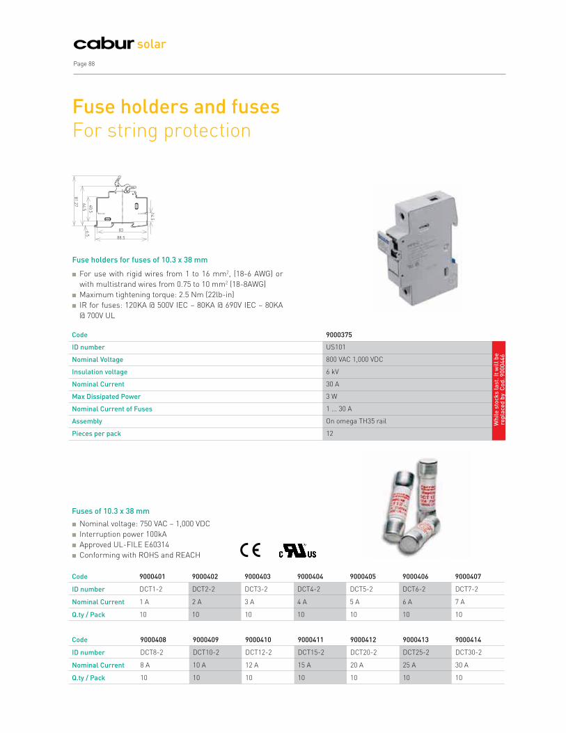
Page 88
solar
Fuse holders and fuses For string protection
For use with rigid wires from 1 to 16 mm2, (18-6 AWG) or
with multistrand wires from 0.75 to 10 mm2 (18-8AWG)
Maximum tightening torque: 2.5 Nm (22lb-in)
IR for fuses: 120KA @ 500V IEC – 80KA @ 690V IEC – 80KA
@ 700V UL
Code 9000401 9000402 9000403 9000404 9000405 9000406 9000407
ID number DCT1-2 DCT2-2 DCT3-2 DCT4-2 DCT5-2 DCT6-2 DCT7-2
Nominal Current 1 A 2 A 3 A 4 A 5 A 6 A 7 A
Q.ty / Pack 10 10 10 10 10 10 10
Fuse holders for fuses of 10.3 x 38 mm
Fuses of 10.3 x 38 mm
Nominal voltage: 750 VAC – 1,000 VDC
Interruption power 100kA
Approved UL-FILE E60314
Conforming with ROHS and REACH
Code 9000408 9000409 9000410 9000411 9000412 9000413 9000414
ID number DCT8-2 DCT10-2 DCT12-2 DCT15-2 DCT20-2 DCT25-2 DCT30-2
Nominal Current 8 A 10 A 12 A 15 A 20 A 25 A 30 A
Q.ty / Pack 10 10 10 10 10 10 10
Code 9000375
ID number US101
Nominal Voltage 800 VAC 1,000 VDC
Insulation voltage 6 kV
Nominal Current 30 A
Max Dissipated Power 3 W
Nominal Current of Fuses 1 ... 30 A
Assembly On omega TH35 rail
Pieces per pack 12
83
88.5
14
.5
6.5
40
.5
64
.5
81
.27
Wh
ile
sto
ck
s l
as
t. I
t w
ill
be
re
pla
ced
by
Co
d.
90
00
44
6

Cabur Solar Page 89
Diodes For strings of photovoltaic panels
Designed to facilitate photovoltaic system designers and
installers in fitting the blocking diode on the solar panels.
The DIN rail clamp makes installation fast and safe.
Operating voltage allows for use of systems according to IEC
60364-7-712 standard.
Code ISDS3516 ISDS102 9000395 SF903GR
ID number KXDS3516 KXDS102 T20HF220 SFR.4/D3A/GR
Description Diode for PV strings Diode for PV strings Diode for PV strings Sectionable diode holder
Insulation voltage
towards the DIN rail
3.75 kVca/ 5 secs 3.75 kVca/ 5 secs 5 kVac/ 60 secs 3 kVac/ 60 secs
Max Inverse Voltage 1.6 kV 2 kV 2.2 kV 1.3 kV
Max. String Voltage 800 V 1,000 V 1.1 kV 650 V
Nominal Current 10 A @ 25°C 10 A @ 25°C 12 A @ 45°C 3 A @ 25°C
Max Operating Current
Transitional
15 A 15 A 250 A x 10 ms 20 A
Max Operating Temperature 45° C 45° C 95° C 45° C
Dissipated power 8 W @ 10 A 16 W @ 10 A 10 W @ 7.5 A; 20 W to 17 A 3.3 W @ 3 A
Connections Faston 6.3 Faston 6.3 Wire terminals Ø 5 mm 4 mm screw-on terminal
Assembly On omega TH35 rail On omega TH35 rail Screwed onto metallic panel
(recommended thickness 3
mm) or heat sink
On omega TH35 rail
Weight 235 g 235 g 54 g 35 g
Dimensions (LxHxD) mm 24x77x80 24x77x80 24x41x25 8x52x52
Quantity per pack 10 10 10 70

solar
Photovoltaic systemsTerminal blocks
FROM PAGE 91 TO PAGE 102
Modular terminal blocks and distribution and control terminal boards suitable for use in photovoltaic systems.
91
95
96
97
98
101
Screw-clamp terminal blocks
QBLOK rail assemblies with two poles
Accessories
Control rail assemblies. UTF meter control operating through CTs and VTs
Control rail assemblies. MCM series
Control rail assemblies. MCT/SA series

Cabur Solar Page 91
Railassembly Series CBC
and relative Accessories
1 - End bracket
2 - ID Number
3 - Cross connection barrier
4 - PTC Easy Bridge cross-connection
5 - Conductor element
6 - Blade fuse*
7 - 5x20 fuse*
8 - CPF/5 tool holder cartridge (fuse / resistance / diode)*
9 – Bridge identification strip
10 - Cross connection barrier
11 - Modular test plugs
12 - Warning plate
*Accessories no suitable for PV applications. For suitable fuses, see Page 88
ctionc 1 23
45
6
7
8
9
10
11
10
12
Screw-clamp terminal blocks 1,000 VDC nominal voltage
To construct the connections of photovoltaic wires with a
section larger than 6 mm², we recommend, inside of the
junction boxes and/or electrical panels, our series of CBC
terminal blocks (for wires with sections between 4 and 35
mm²), CBD (for wires with sections between 4 and 70 mm²),
GPA (for wires with sections between 50 and 240 mm²) and
GPM (for wires with sections between 95 and 240 mm²).
These terminal block families are particularly suitable for
photovoltaic environments both for their well known technical-
qualitative features which have made them famous in various
other application fields, and above all because they can be
used under direct current up to 1,000V.
To connect the strings, Line 3 and 4 photovoltaic connectors
are recommended, while for connections with high current the
terminal blocks found on the pages below are recommended.
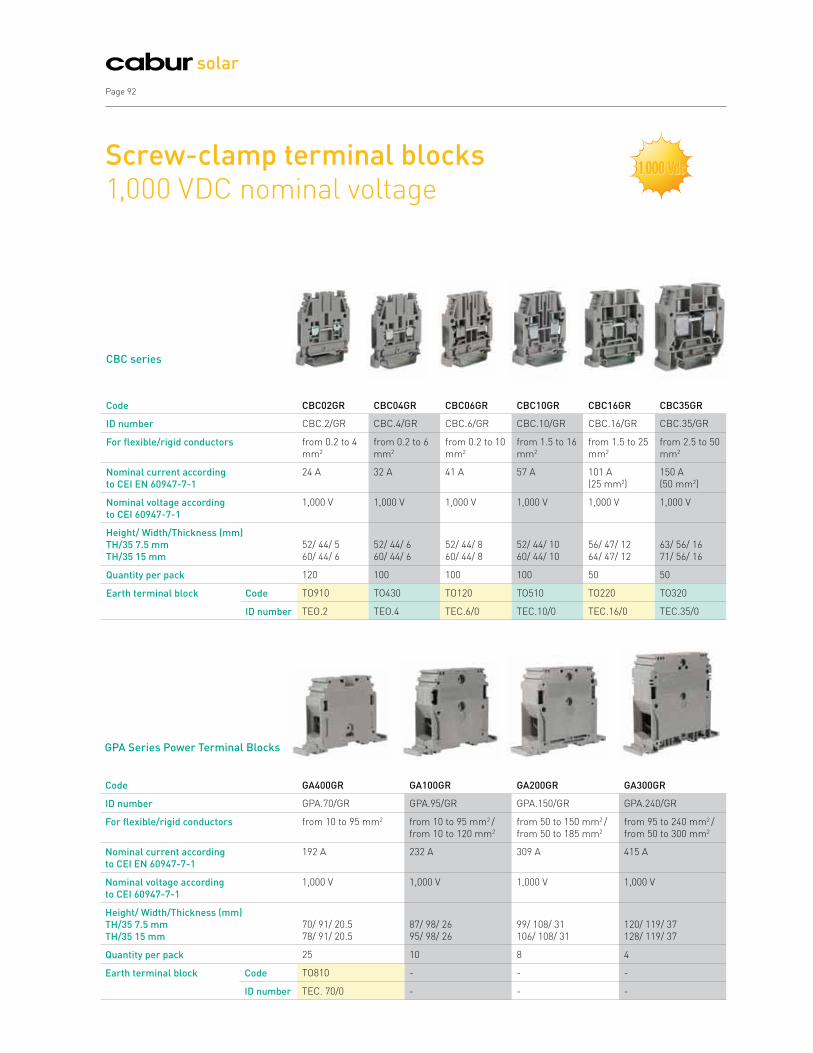
Page 92
solar
Screw-clamp terminal blocks 1,000 VDC nominal voltage
Code CBC02GR CBC04GR CBC06GR CBC10GR CBC16GR CBC35GR
ID number CBC.2/GR CBC.4/GR CBC.6/GR CBC.10/GR CBC.16/GR CBC.35/GR
For flexible/rigid conductors from 0.2 to 4
mm2
from 0.2 to 6
mm2
from 0.2 to 10
mm2
from 1.5 to 16
mm2
from 1.5 to 25
mm2
from 2.5 to 50
mm2
Nominal current according
to CEI EN 60947-7-1
24 A 32 A 41 A 57 A 101 A
(25 mm2)
150 A
(50 mm2)
Nominal voltage according
to CEI 60947-7-1
1,000 V 1,000 V 1,000 V 1,000 V 1,000 V 1,000 V
Height/ Width/Thickness (mm)
TH/35 7.5 mm
TH/35 15 mm
52/ 44/ 5
60/ 44/ 6
52/ 44/ 6
60/ 44/ 6
52/ 44/ 8
60/ 44/ 8
52/ 44/ 10
60/ 44/ 10
56/ 47/ 12
64/ 47/ 12
63/ 56/ 16
71/ 56/ 16
Quantity per pack 120 100 100 100 50 50
Earth terminal block Code TO910 TO430 TO120 TO510 TO220 TO320
ID number TEO.2 TEO.4 TEC.6/0 TEC.10/0 TEC.16/0 TEC.35/0
Code GA400GR GA100GR GA200GR GA300GR
ID number GPA.70/GR GPA.95/GR GPA.150/GR GPA.240/GR
For flexible/rigid conductors from 10 to 95 mm2 from 10 to 95 mm2 /
from 10 to 120 mm2
from 50 to 150 mm2 /
from 50 to 185 mm2
from 95 to 240 mm2 /
from 50 to 300 mm2
Nominal current according
to CEI EN 60947-7-1
192 A 232 A 309 A 415 A
Nominal voltage according
to CEI 60947-7-1
1,000 V 1,000 V 1,000 V 1,000 V
Height/ Width/Thickness (mm)
TH/35 7.5 mm
TH/35 15 mm
70/ 91/ 20.5
78/ 91/ 20.5
87/ 98/ 26
95/ 98/ 26
99/ 108/ 31
106/ 108/ 31
120/ 119/ 37
128/ 119/ 37
Quantity per pack 25 10 8 4
Earth terminal block Code TO810 - - -
ID number TEC. 70/0 - - -
CBC series
GPA Series Power Terminal Blocks
,,

Cabur Solar Page 93
Screw-clamp terminal blocks
Code CB240 CB340 CB440
ID number CBD.4 CBD.6 CBD.10
For flexible/rigid conductors from 0.5 to 6 mm2 from 0.5 to 10 mm2 from 0.5 to 16 mm2
Nominal current according to CEI EN
60947-7-1
32 A 41 A 57 A
Nominal voltage according to CEI
60947-7-1
1,000 V 1,000 V 1,000 V
Height/ Width/Thickness (mm)
TH/35 7.5 mm
TH/35 15 mm
52/ 44/ 6.5
60/ 44/ 6.5
52/ 44/ 8
60/ 44/ 8
52/ 44/ 10
63/ 44/ 10
Quantity per pack 100 100 100
CBD Series Terminal
Blocks
Code CB510 CB610 CB710 CB810
ID number CBD.16 CBD.35 CBD.50 CBD.70
For flexible/rigid conductors from 0.5 to 25 mm2 from 0.5 to 35 mm2 from 1.5 to 50 mm2 from 1.5 to 95 mm2
Nominal current according to CEI EN
60947-7-1
76 A 125 A 150 A 192 A
Nominal voltage according to CEI
60947-7-1
1,000 V 1,000 V 1,000 V 1,000 V
Height/ Width/Thickness (mm)
TH/35 7.5 mm
TH/35 15 mm
57/ 47/ 12
65/ 47/ 12
60/ 52/ 16
68/ 52/ 16
62/ 57/ 18
70/ 57/ 18
71/ 62/ 20.5
79/ 62/ 20.5
Quantity per pack 50 75 50 40
CBD Series Terminal
Blocks
,,

Page 94
solar
Code GP500 GP800 GP300 GP600 GP900
ID number GPM.150/BC GPM.240/BC GPM.95/CC GPM.150/CC GPM.240/CC
For flexible/rigid conductors from 50 to 185 mm2
from 35 to 185 mm2
from 95 to 300
mm2
from 35 to 120 mm2
from 25 to 120 mm2
from 50 to 185 mm2
from 35 to 185 mm2
from 95 to 300
mm2
Nominal current according to CEI EN
60947-7-1
353 A 452 A 269 A 353 A 452 A
Nominal voltage according to CEI
60947-7-1
1,000 V 1,000 V 1,000 V 1,000 V 1,000 V
Height/ Width/Thickness (mm)
TH/35 7.5 mm
TH/35 15 mm
81/ 200/ 42
88/ 200/ 42
89/ 250/ 52
96/ 250/ 52
81/ 176/ 32
88/ 176/ 32
81/ 200/ 42
88/ 200/ 42
89/ 250/ 52
96/ 250/ 52
Quantity per pack 6 4 10 6 4
Version for anchoring to the panel
Code GP510 GP810 GP310 GP610 GP910
ID number GPM.150/BC/FIX GPM.240/BC/FIX GPM.95/CC/FIX GPM.150/CC/FIX GPM.240/CC/FIX
GPM Series Power Terminal Blocks
Code GP100 GP400 GP700 GP200
ID number GPM.95/BB GPM.150/BB GPM.240/BB GPM.95/BC
For flexible/rigid conductors - - - from 35 to 120 mm2 /
from 25 to 120 mm2
Nominal current according to CEI EN
60947-7-1
269 A 353 A 452 A 269 A
Nominal voltage according to CEI
60947-7-1
1,000 V 1,000 V 1,000 V 1,000 V
Height/ Width/Thickness (mm)
TH/35 7.5 mm
TH/35 15 mm
81/ 176/ 32
88/ 176/ 32
81/ 200/ 42
88/ 200/ 42
89/ 250/ 52
96/ 250/ 52
81/ 176/ 32
88/ 176/ 32
Quantity per pack 10 6 4 10
Version for anchoring to the panel
Code GP110 GP410 GP710 GP210
ID number GPM.95/BB/FIX GPM.150/BB/FIX GPM.240/BB/FIX GPM.95/BC/FIX
Screw-clamp terminal blocks 1,000 VDC nominal voltage
*Version for anchoring to the panel code GP510 is supplied in packs of 4 pieces.
,,

Cabur Solar Page 95
Two pole QBLOK rail assembly Distribution terminal board
Code QBLOK2100 QBLOK2125 QBLOK2126
ID number QBLOK2P100A7 QBLOK2P125A11 QBLOK2P125A15
Description
Rail assembly with 2 holes ø 7.5
mm + 5 holes ø 5.4 mm
Rail assembly with 2 holes ø 9 mm +
2 holes ø 7.5 mm + 7 holes ø 5.4 mm
Rail assembly with 2 holes ø 9 mm +
2 holes ø 7.5 mm + 11 holes ø 5.4 mm
Height/ Width/ Thickness
TH/35 7.5 mm 52/49/72 52/49/109 52/97/137
TH/35 15 mm 59/49/72 59/49/109 59/97/137
Use/Type Bipolar distribution terminal board Bipolar distribution terminal board Bipolar distribution terminal board
Nominal section (mm2) 25 35 35
Connection capacity (hole ø 9 mm)
Flexible conductors (mm2) - 10 ÷ 35 10 ÷ 35
Rigid conductors (mm2) - 10 ÷ 35 10 ÷ 35
Max flexible conductor with terminal (mm2) -
terminal ID number - 25 - WP250/29 25 - WP250/29
Connection capacity (hole ø 7.5 mm)
Flexible conductors (mm2) 10 ÷ 25 10 ÷ 25 10 ÷ 25
Rigid conductors (mm2) 10 ÷ 25 10 ÷ 25 10 ÷ 25
Max flexible conductor with terminal (mm2) -
terminal ID number 16 - WP160/22 16 - WP160/22 16 - WP160/22
Connection capacity (hole ø 5.4 mm)
Flexible conductors (mm2) 2.5 ÷ 6 2.5 ÷ 6 2.5 ÷ 6
Rigid conductors (mm2) 2.5 ÷ 6 2.5 ÷ 6 2.5 ÷ 6
Max flexible conductor with terminal (mm2) -
terminal ID number 4 - WP40/16 4 - WP40/16 4 - WP40/16
Rated voltage/Rated current/Gauge 1,000V/100A/- acc. to EN 60947-1 1,000V/125A/- acc. to EN 60947-1 1,000V/125A/- acc. to EN 60947-1
Short term current allowed (lcw)
3 kA (effective for 1s) according to
EN 60947-7-1
4.2 kA (effective for 1s) according to
EN 60947-7-1
4.2 kA (effective for 1s) according to
EN 60947-7-1
Impulse withstand voltage / Degree of
pollution 8 kV/3 8 kV/3 8 kV/3
Stripping length (mm) 13 13 13
Test/Recommended tightening torque 1.8/2.2 Nm 1.8/2.2 Nm 1.8/2.2 Nm
Certifications IMQ IMQ IMQ
Quantity per pack 4 2 2
IMQ certification pending
,,

Page 96
solar
Two pole QBLOK rail assemblies Accessories
Technical characteristics of QBLOK
rail assemblies
Code NU0851 NU1051 BT005
ID number CNU/8/51/... CNU/10/51/... BTU for PR/DIN and PR/3
Description ID label (numbered or neutral) ID label (numbered or neutral) End bracket
Quantity per pack 1,500 tags 1,500 tags 25
Code BT003-BT007 PR003 PR005
ID number BT/3-BTO only for PR/3 PR/3/AC in steel PR/3/AS same with slots
Description End bracket Mounting rail conforms to IEC 60715 Mounting rail conforms to IEC 60715
Quantity per pack 25 40 40
Mounted onto PR/3 rails conforming to IEC 60715
standards TH/35 type or directly onto the panel
Insulating supports made of 6.6 UL94V-0 polyamide
and insulating cover of transparent polycarbonate
Insulating screen for each conducting busbar
Power supply holes intentionally offset for better
conductor wiring
Possible to label each bar with a CNU/8 or CNU/10 tag
Conform to EN 60947-7-1
Nominal insulation voltage: 1,000 V - according to EN
60947-1 (AC or DC effective value)
Appropriate for photovoltaic systems

Technical features
Rated cross-section: 6 mm2
Connection capacity:
flexible conductors: 0.5 ÷ 6 mm2
rigid conductors: 0.5 ÷ 6 mm2
Hole for inserting conductors: ø 4.1 (mm)
Tightening torque: 1.2 (Nm)
Rated current (according to IEC 60947-7-1 regulations): 57 A
Rated voltage (according to IEC 60947-7-1 regulations): 500 V
Voltage stability at impulse/degree of pollution 6 KV/3
Cabur Solar Page 97
Control rail assemblies UTF meter control operating through CTs and VTs
Cabur control rail assemblies are designed to allow electricity
providers and Users the possibility of easily checking on the
measuring instruments, without interrupting current flow during
control or during possible replacement of the instruments.
ENEL has adopted a special colour system to identify phases
according to the geographic areas where the rail assemblies will
be installed.
Every rail assembly is composed of an insulating base which
holds the terminal blocks, in copper-zinc alloy, of the volt and
amp meter circuits, and the devices for disconnection and short
circuit operations. The base of the single-phase rail assembly
is made of heat-hardened resin (black phenol resin). For the bi-
and three-phase rail assemblies, the insulating base is made of
Kelon (Keramic + Nylon). This is a polymer with a nylon 6 base,
self-extinguishing UL94V-0, to which is added special ceramic
spheres, after which it is thermally stabilized. The inclusion of
the microspheres and the thermal procedure render the final
product extremely resilient -- rigid but still able to resist shocks
and wear.
Every rail assembly has a transparent cover (in cellulose acetate),
provided with special screws that cannot be lost, by which the
whole can be sealed.
Every screw has a special hole for the passage of the lead-
sealing wire for UTF.
The phases are indicated in different colours, to be specified when
ordering. The rail assemblies should be positioned upstream
of the two-direction meter or, as in the CEI 82-25 electrical
diagrams, between meter and delivery point.
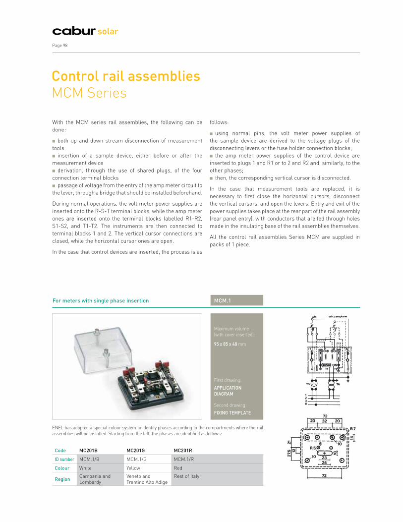
Page 98
solar
Control rail assemblies MCM Series
With the MCM series rail assemblies, the following can be
done:
both up and down stream disconnection of measurement
tools
insertion of a sample device, either before or after the
measurement device
derivation, through the use of shared plugs, of the four
connection terminal blocks
passage of voltage from the entry of the amp meter circuit to
the lever, through a bridge that should be installed beforehand.
During normal operations, the volt meter power supplies are
inserted onto the R-S-T terminal blocks, while the amp meter
ones are inserted onto the terminal blocks labelled R1-R2,
S1-S2, and T1-T2. The instruments are then connected to
terminal blocks 1 and 2. The vertical cursor connections are
closed, while the horizontal cursor ones are open.
In the case that control devices are inserted, the process is as
follows:
using normal pins, the volt meter power supplies of
the sample device are derived to the voltage plugs of the
disconnecting levers or the fuse holder connection blocks;
the amp meter power supplies of the control device are
inserted to plugs 1 and R1 or to 2 and R2 and, similarly, to the
other phases;
then, the corresponding vertical cursor is disconnected.
In the case that measurement tools are replaced, it is
necessary to first close the horizontal cursors, disconnect
the vertical cursors, and open the levers. Entry and exit of the
power supplies takes place at the rear part of the rail assembly
(rear panel entry), with conductors that are fed through holes
made in the insulating base of the rail assemblies themselves.
All the control rail assemblies Series MCM are supplied in
packs of 1 piece.
For meters with single phase insertion MCM.1
Maximum volume
(with cover inserted):
95 x 85 x 48 mm
First drawing:
APPLICATION
DIAGRAM
Second drawing:
FIXING TEMPLATE
ENEL has adopted a special colour system to identify phases according to the compartments where the rail
assemblies will be installed. Starting from the left, the phases are identified as follows:
Code MC201B MC201G MC201R
ID number MCM.1/B MCM.1/G MCM.1/R
Colour White Yellow Red
RegionCampania and
Lombardy
Veneto and
Trentino Alto Adige
Rest of Italy

Cabur Solar Page 99
For meters with three-phase and neutral insertion MCM.3
Maximum volume
(with cover inserted):
95 x 85 x 48 mm
First drawing:
APPLICATION
DIAGRAM
Second drawing:
FIXING TEMPLATE
ENEL has adopted a special colour system to identify phases according to the compartments where the rail
assemblies will be installed. Starting from the left, the phases are identified as follows:
Code MC203B MC203G MC203R
ID number MCM.3/B MCM.3/G MCM.3/R
Colour White Yellow Red
RegionCampania and
Lombardy
Veneto and
Trentino Alto Adige
Rest of Italy
For meters with ARON insertion MCM.2
Maximum volume
(with cover inserted):
170 x 85 x 48 mm
First drawing:
APPLICATION
DIAGRAM
Second drawing:
FIXING TEMPLATE
ENEL has adopted a special colour system to identify phases according to the compartments where the rail
assemblies will be installed. Starting from the left, the phases are identified as follows:
Code MC202B MC202G MC202R
ID number MCM.2/B MCM.2/G MCM.2/R
Colour White Yellow Red
RegionCampania and
Lombardy
Veneto and
Trentino Alto Adige
Rest of Italy

Page 100
solar
For meters with three-phase and neutral insertion MCM.3/VE
Maximum volume
(with cover inserted):
245 x 85 x 48 mm
First drawing:
APPLICATION
DIAGRAM
Second drawing:
FIXING TEMPLATE
ENEL has adopted a special colour system to identify phases according to the compartments where the rail
assemblies will be installed. Starting from the left, the phases are identified as follows:
Code MC233B MC233G MC233R
ID number MCM.3/VE/B MCM.3/VE/G MCM.3/VE/R
Colour White Yellow Red
Region Campania and LombardyVeneto and Trentino Alto
Adige
Rest of Italy

Cabur Solar Page 101
Control rail assemblies MCT/SA Series
The series MCT/SA differs from the MCM series in the
following ways:
switching of voltages is done through the use of cursors,
rather than levers
both entry and exit of power supplies takes place at the front
of the rail assembly, with conductors that pass through open
slots created on the upper and lower walls of the cover
there is a door cover with safety blocks which
prevent it from closing when the cursors are not in
the proper position. Methods of use for MCT/SA rail
assemblies are the same as those for the MCM series.
All the control rail assemblies Series MCT/SA are supplied in
packs of 1 piece.
For meters with single phase insertion MCT.1/SA
Maximum volume
(with cover inserted):
95 x 85 x 48 mm
First drawing:
APPLICATION
DIAGRAM
Second drawing:
FIXING TEMPLATE
ENEL has adopted a special colour system to identify phases according to the compartments where the rail
assemblies will be installed. Starting from the left, the phases are identified as follows:
Code MC401B MC401G MC401R
ID number MCT.1/SA/B MCT.1/SA/G MCT.1/SA/R
Colour White Yellow Red
Region Campania and LombardyVeneto and Trentino Alto
Adige
Rest of Italy
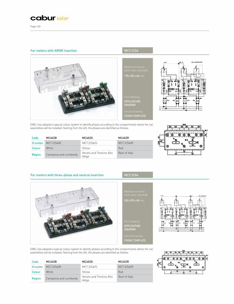
Page 102
solar
For meters with three-phase and neutral insertion MCT.3/SA
Maximum volume
(with cover inserted):
245 x 85 x 48 mm
First drawing:
APPLICATION
DIAGRAM
Second drawing:
FIXING TEMPLATE
ENEL has adopted a special colour system to identify phases according to the compartments where the rail
assemblies will be installed. Starting from the left, the phases are identified as follows:
Code MC403B MC403G MC403R
ID number MCT.3/SA/B MCT.3/SA/G MCT.3/SA/R
Colour White Yellow Red
Region Campania and LombardyVeneto and Trentino Alto
Adige
Rest of Italy
For meters with ARON insertion MCT.2/SA
Maximum volume
(with cover inserted):
170 x 85 x 48 mm
First drawing:
APPLICATION
DIAGRAM
Second drawing:
FIXING TEMPLATE
ENEL has adopted a special colour system to identify phases according to the compartments where the rail
assemblies will be installed. Starting from the left, the phases are identified as follows:
Code MC402B MC402G MC402R
ID number MCT.2/SA/B MCT.2/SA/G MCT.2/SA/R
Colour White Yellow Red
Region Campania and LombardyVeneto and Trentino Alto
Adige
Rest of Italy

Cabur Solar Page 103
Code index
CODE PAGE
9000373 87
9000374 87
9000375 76,88
9000392 80,82
9000393 80,82
9000394 80,82
9000395 89
9000401 88
9000402 88
9000403 88
9000404 88
9000405 88
9000406 88
9000407 88
9000408 88
9000409 88
9000410 88
9000411 88
9000412 88
9000413 88
9000414 88
9000417 85,86
9000418 85,86
9000419 85,86
9000420 85,86
9000430 85
9000431 85
9000432 85
9000434 85
9000499 76
9000502 84
9000503 84
9000504 84
9000513 84
BT003 96
BT005 96
BT007 96
CB240 93
CB340 93
CB440 93
CB510 93
CODE PAGE
CB610 93
CB710 93
CB810 93
CBC02GR 92
CBC04GR 92
CBC06GR 92
CBC10GR 92
CBC16GR 92
CBC35GR 92
GA100GR 92
GA200GR 92
GA300GR 92
GA400GR 92
GP100 94
GP110 94
GP200 94
GP210 94
GP300 94
GP310 94
GP400 94
GP410 94
GP500 94
GP510 94
GP600 94
GP610 94
GP700 94
GP710 94
GP800 94
GP810 94
GP900 94
GP910 94
IS0601207 34
IS0601209 34
IS0701207 30,31,32
IS0701209 30,31,32
IS101534611 41
IS101740277 41
IS13112 30,47
IS13242 30
IS14110 34,47,68,76
IS14240 29,34,37,47

Page 104
solar Code index
CODE PAGE
IS42320L 33
IS42320S 33,47
IS42420 35
IS461394461 40
IS51400 27,36
IS52400 27,36
IS551394462 41,42
IS651394461 41,42
IS651394462 40,42
IS661394461 40,42
ISA0101FXCA06 62
ISA0101FXCA10 62
ISA0101HXCA06 62
ISA0101HXCA10 62
ISA0201FXCA06 62
ISA0201FXCA10 62
ISA0201HXCA06 62
ISA0201HXCA10 62
ISA0202FXCA06 62
ISA0202FXCA10 62
ISA0202HXCA06 62
ISA0202HXCA10 62
ISA0301FXCA06 62
ISA0301FXCA10 62
ISA0301HXCA06 62
ISA0301HXCA10 62
ISA0302FXCA06 62
ISA0302FXCA10 62
ISA0302HXCA06 62
ISA0302HXCA10 62
ISA0401FXCA06 62
ISA0401FXCA10 62
ISA0401HXCA06 62
ISA0401HXCA10 62
ISA0402FXCA06 62
ISA0402FXCA10 62
ISA0402HXCA06 62
ISA0402HXCA10 62
ISB0101FXCA06 61
ISB0101FXCA10 61
ISB0101HXCA06 61
CODE PAGE
IS14242 35
IS15000 31,32,33,37
IS15001 31,32,33,37
IS15240 31,37,47
IS15242 31,37
IS15341 32,37
IS15342 32
IS15BLOCK 36
IS15SBLOCK 36
IS201534611 41
IS201740277 41
IS211579002 47
IS23113 30,47
IS23243 30
IS24111 34,47,68,76
IS24241 29,34,37,47
IS24243 35
IS25241 31,37,47
IS25243 31,37
IS25342 32,37
IS25343 32
IS261394461 39,47
IS301102855 43,47
IS301394461 39,42
IS301394462 39,42,47
IS301394738 40
IS3110 35,43
IS3152 39,40,41,44,47
IS3153 26,27,30,31,32,44,47
IS3154 26,27,34,44,47
IS3155 44
IS31579002 43,45
IS3161 26,43,46
IS3170 43,45
IS3170L 43
IS401394461 39,42
IS401394462 39,42,47
IS401394738 40
IS41310L 33
IS41310S 33,47
IS41410 35

Cabur Solar Page 105
CODE PAGE
ISB0101HXCA10 61
ISB01FDCA06 55
ISB01FDCA08 55
ISB01FDCA10 55
ISB01FXCA06 55
ISB01FXCA08 55
ISB01FXCA10 55
ISB01HXCA06 54
ISB01HXCA08 54
ISB01HXCA10 54
ISB0201FXCA06 61
ISB0201FXCA10 61
ISB0201HXCA06 61
ISB0201HXCA10 61
ISB0202FXCA06 61
ISB0202FXCA10 61
ISB0202HXCA06 61
ISB0202HXCA10 61
ISB02FDCA06 55
ISB02FDCA08 55
ISB02FDCA10 55
ISB02FXCA06 55
ISB02FXCA08 55
ISB02FXCA10 55
ISB02HDCA06 54
ISB02HDCA08 54
ISB02HDCA10 54
ISB02HXCA06 54
ISB02HXCA08 54
ISB02HXCA10 54
ISB0301FXCA06 61
ISB0301FXCA10 61
ISB0301HXCA06 61
ISB0301HXCA10 61
ISB0302FXCA06 61
ISB0302FXCA10 61
ISB0302HXCA06 61
ISB0302HXCA10 61
ISB0303FXCA06 61
ISB0303FXCA10 61
ISB03FDCA06 55
CODE PAGE
ISB03FDCA08 55
ISB03FDCA10 55
ISB03FXCA06 55
ISB03FXCA08 55
ISB03FXCA10 55
ISB03HDCA06 54
ISB03HDCA08 54
ISB03HDCA10 54
ISB03HXCA06 54
ISB03HXCA08 54
ISB03HXCA10 54
ISB0401FXCA06 61
ISB0401FXCA10 61
ISB0401HXCA06 61
ISB0401HXCA10 61
ISB0402FXCA06 61
ISB0402FXCA10 61
ISB0402HXCA06 61
ISB0402HXCA10 61
ISB04FDCA06 55
ISB04FDCA08 55
ISB04FDCA10 55
ISB04FXCA06 55
ISB04FXCA08 55
ISB04FXCA10 55
ISB04HDCA06 54
ISB04HDCA08 54
ISB04HDCA10 54
ISB04HXCA06 54
ISB04HXCA08 54
ISB04HXCA10 54
ISB06FDCB06 55
ISB06FDCB08 55
ISB06FDCB10 55
ISB06FXCB06 55
ISB06FXCB08 55
ISB06FXCB10 55
ISB06HDCB06 54
ISB06HDCB08 54
ISB06HDCB10 54
ISB06HXCB06 54
Code index

Page 106
solar Code index
CODE PAGE
ISB06HXCB08 54
ISB06HXCB10 54
ISB08FDCB06 55
ISB08FDCB08 55
ISB08FDCB10 55
ISB08FXCB06 55
ISB08FXCB08 55
ISB08FXCB10 55
ISB08HDCB06 54
ISB08HDCB08 54
ISB08HDCB10 54
ISB08HXCB06 54
ISB08HXCB08 54
ISB08HXCB10 54
ISCS02100 48
ISCS02101 48
ISCS02500 48
ISCS02501 48
ISCS04100 48
ISCS04101 48
ISCS04400 48
ISCS04401 48
ISCS06100 48
ISCS06101 48
ISCS06300 48
ISCS06301 48
ISCS10200 48
ISCS10201 48
ISDS102 89
ISDS3516 89
ISE04FXCD10 68
ISE04HXCD10 68
ISE08FXCD10 68
ISE08HXCD10 68
ISE16FXCE10 68
ISE16HXCE10 68
ISFIX00 13
ISFIX00B 13
ISFIX00C 13
ISFIX00D 13
ISFIXAGL 23
CODE PAGE
ISFIXCLP 15,17,18,24
ISFIXCUR 23
ISFIXDAF 15,24
ISFIXDST 19
ISFIXDUO 15,17,24
ISFIXG 15,24
ISFIXINC 17,18
ISFIXPAL 17
ISFIXPAZ 17
ISFIXPPL 6,20
ISFIXSP1 6,16,18
ISFIXSP2 6,16,18
ISFIXSP31I 18
ISFIXSP31T 18
ISFIXSP35I 18
ISFIXSP35T 18
ISFIXSP38I 18
ISFIXSP38T 18
ISFIXSP40I 18
ISFIXSP40T 18
ISFIXSP42I 18
ISFIXSP42T 18
ISFIXSP46I 18
ISFIXSP46T 18
ISFIXSP50I 18
ISFIXSP50T 18
ISFIXSPAZ31T 14,23
ISFIXSPAZ35T 14,23
ISFIXSPAZ38T 14,23
ISFIXSPAZ40T 14,23
ISFIXSPAZ42T 14,23
ISFIXSPAZ46T 14,23
ISFIXSPAZ50T 14,23
ISFIXSPAZI 14,23
ISFIXSPPL31T 14,23
ISFIXSPPL35T 14,23
ISFIXSPPL38T 14,23
ISFIXSPPL40T 14,23
ISFIXSPPL42T 14,23
ISFIXSPPL46T 14,23
ISFIXSPPL50T 14,23

Cabur Solar Page 107
CODE PAGE
ISPD500V3G0A 81
ISPD600V3G0A 76,81
ISPD800V3G0A 81
ISPECU1 71,72,73,75,76
ISPIN34060F 30,31,32
ISPIN34060M 30,31,32
ISPIN44060F 34
ISPIN44060M 34
ISPVLT1 75,76
ISVOL3F 30
ISVOL3FGPGC 32
ISVOL3FGPGL 32
ISVOL3GF 31
ISVOL3GFL 31
ISVOL3GM 31
ISVOL3GML 31
ISVOL3M 30
ISVOL3MGPGC 32
ISVOL3MGPGL 32
ISVOL4F 34
ISVOL4M 34
MC201B 98
MC201G 98
MC201R 98
MC202B 99
MC202G 99
MC202R 99
MC203B 99
MC203G 99
MC203R 99
MC233B 100
MC233G 100
MC233R 100
MC401B 101
MC401G 101
MC401R 101
MC402B 102
MC402G 102
MC402R 102
MC403B 102
MC403G 102
Code index
CODE PAGE
ISFIXSPPLI 14,23
ISFIXVLO 15,24
ISFIXVTAZ 14,23
ISFIXVTAZ60 14,23
ISFIXVTAZ65 14,23
ISFIXVTAZ70 14,23
ISFIXVTAZ75 14,23
ISKIT03A 47
ISKIT04 47
ISKITYCO 47
ISL0101FXCA06 64
ISL0101FXCA10 64
ISL0101HXCA06 64
ISL0101HXCA10 64
ISL0201FXCA06 64
ISL0201FXCA10 64
ISL0201HXCA06 64
ISL0201HXCA10 64
ISL0301FXCA06 64
ISL0301FXCA10 64
ISL0301HXCA06 64
ISL0301HXCA10 64
ISL0401FXCA06 64
ISL0401FXCA10 64
ISL0401HXCA06 64
ISL0401HXCA10 64
ISPAMP4 74,76
ISPAN3F 30
ISPAN3M 30
ISPAN4F 34
ISPAN4M 34
ISPD1000V3G0A 76,81
ISPD14555 79
ISPD275V1G0A 82
ISPD275V0G1A 82
ISPD275V2G1B 83
ISPD440V0G1A 82
ISPD440V1G0A 82
ISPD440V3G1B 83
ISPD440V4G0B 83
ISPD440V4G1B 83

Page 108
solar
CODE PAGE
MC403R 102
NU0851 96
NU1051 96
PR003 96
PR005 96
QBLOK2100 95
QBLOK2125 95
QBLOK2126 95
SF903GR 89
TO120 92
TO220 92
TO320 92
TO430 92
TO510 92
TO810 92
TO910 92
UMCT3127 44
UMCT3128 44
UMCT3129 44
UMCT3149 25,27,30,31,32,34,35,3940,41,43,44,47
UMCT3153 44
UMCT3154 44
XCSD30C 74,76
D031G14A - 2014 EDITION
Cabur is mindful of safeguarding and protecting the environment. This information
has been printed on paper originating from responsibly managed forests and other
controlled origins certified by the Forest Stewardship Council (FSC).
SYSTEMS AND PRODUCTS
FOR THE CONNECTION
OF ELECTRICAL PANELS
ELECTRONIC PRODUCTS
FOR ELECTRICAL PANELS
PHOTOVOLTAIC SYSTEM
CONNECTIONS AND
PROTECTION
INDUSTRIAL MARKING
SYSTEMS
Cabur Srl
17041 - Altare (SV)
Località Isola Grande, 45 - IT
T. +39 019 58999.1
F. +39 019 58999280
www.cabur.it
French Branch
Cabur France
71530 Champforgeuil
12, rue André-Marie Ampère
T. +33 (0)3.85.48.49.10
F. +33 (0)3.85.41.17.60
www.cabur.eu
Romanian Branch
Cabur Romania
Strada Calea Plevnei nr. 139
Corp B camera 25,26 sector 6
Bucharest
T. +40 021.31.17.140
F. +40 021.31.17.140
www.cabur.eu
ELECTRONIC PRODUCTS SYSTEMS AND PRODUCTS PHOTOVOLTAIC SYSTEMTS INDUSTRIAL MARKING


![Solar Photovoltaic Electric System Protection Prof. Brian Norton … · 2018. 8. 15. · • [2] Sizing fuses for Photovoltaic Systems per the National Electrical Code, 2012, Mersen](https://img.pdfslide.net/doc/110x75/60e4108c721af6303603ad47/solar-photovoltaic-electric-system-protection-prof-brian-norton-2018-8-15.jpg)