Embed Size (px)
Citation preview
Solar America Board for Codes and Standardswww.solarabcs.org
Photovoltaic System Grounding
Prepared by:
John C. Wiles, Jr.Southwest Technology Development Institute
College of EngineeringNew Mexico State University
October 2012
2 Photovoltaic System Grounding
DisclaimerThis report was prepared as an account of work sponsored by an agency of the United States government. Neither the United States government nor any agency thereof, nor any of their employees, makes any warranty, express or implied, or assumes any legal liability or responsibility for the accuracy, completeness, or usefulness of any information, apparatus, product, or process disclosed, or represents that its use would not infringe privately owned rights. Reference herein to any specific commercial product, process, or service by trade name, trademark, manufacturer, or otherwise does not necessarily constitute or imply its endorsement, recommendation, or favoring by the United States government or any agency thereof. The views and opinions of authors expressed herein do not necessarily state or reflect those of the United States government or any agency thereof.
Download a copy of the report:www.solarabcs.org/systemgrounding
3Solar America Board for Codes and Standards Report
Executive Summary
Photovoltaic (PV) power systems are capable of producing hazardous voltages and currents for decades. To ensure the safety of the public for these extended periods of time, PV systems must be properly designed and installed using the highest standards of workmanship.
This paper addresses the requirements for PV system grounding contained in the U.S. National Electrical Code® (NEC®) published by the National Fire Protection Association (NFPA). The NEC and the NEC Handbook are copyrighted by NFPA and the term NFPA-70 is a trademark owned by the NFPA (NFPA, 2011). It does not address in any detail the various American or European standards that are used to design and produce electrical equipment, nor does it cover the many electrical codes used in other countries.
In the United States, the NEC establishes the legal installation requirements for PV systems, and these requirements are somewhat complex. The NEC requires that all exposed or accessible PV equipment and circuits be properly connected to earth (grounded) using specified methods and equipment. Source circuits in PV systems may be grounded or ungrounded as explained in this paper.
As installed PV systems age, grounding issues emerge that impact system safety. These issues include deteriorating electrical connections, inadequate grounding device design and installation, and the effects of non-code compliant system installations. Many of the required ground-fault protection devices in use today do not detect all possible ground faults, and, in some cases, fires and equipment damage have resulted from undetected ground faults. Both the NEC and Underwriters Laboratories (UL) hardware safety standards for the certification/listing of equipment are being revised to address many of these issues.
“As installed PV systems age, grounding issues emerge that impact system safety.”
4 Photovoltaic System Grounding
Table of Contents
DISCLAIMER ......................................................................................................................... 2
EXECUTIVE SUMMARY ........................................................................................................ 3
AUTHOR BIOGRAPHY ......................................................................................................... 4
SOLAR AMERICA BOARD FOR CODES AND STANDARDS ................................................ 5
ACKNOWLEDGEMENTS ....................................................................................................... 5
INTRODUCTION ................................................................................................................... 6
DEFINITIONS ........................................................................................................................ 7
NATIONAL ELECTRICAL CODE REQUIREMENTS ...................................................... 9
SYSTEM GROUNDING .......................................................................................................... 13
MICROINVERTERS AND AC PV MODULES—DIFFERENT REQUIREMENTS ..................... 18
GROUND FAULTS AND GROUND-FAULT PROTECTION DEVICES ..................................... 20
THE CONNECTION TO EARTH ..................................................................................... 25
UTILITY VS NEC REQUIREMENTS ...................................................................................... 26
ACRONYMS .......................................................................................................................... 27
REFERENCES ........................................................................................................................ 28
5Solar America Board for Codes and Standards Report
Author Biography
John C. Wiles, Jr.
John Wiles is a senior research engineer at the Southwest Technology Development Institute, College of Engineering at New Mexico State University in Las Cruces, New Mexico.
He bought his first copy of the National Electrical Code® (NEC®) in 1961 and rewired his parent’s home to the latest NEC requirements. After graduating from West Virginia University with a bachelor’s degree in electrical engineering, he became an officer in the United States Air Force. He earned a master’s degree in electrical engineering and spent 24 years in the Air Force working on automatic control systems and tactical weapons systems. He has taught college courses at West Virginia University and the U.S. Naval Academy. He installed his first photovoltaic (PV) power system in 1984 and has been involved in the design, installation, inspection, and testing of PV systems for 28 years. He is a member of the Underwriters Laboratories Standards Technical Panels for PV modules, inverters, racks, and direct current PV arc fault interrupters. He is secretary of the PV Industry Forum, an organization that develops and submits PV proposals for improving the NEC. He writes articles on PV and the NEC for the International Association of Electrical Inspectors News and gives PV/NEC presentations throughout the country to PV designers, installers, and electrical inspectors. He lives with his wife Patti, two dogs, and a cat in an energy-efficient home with a 5-kilowatt utility-interactive PV system and full house battery backup.
Solar America Board For Codes And Standards
The Solar America Board for Codes and Standards (Solar ABCs) is a collaborative effort among experts to formally gather and prioritize input from the broad spectrum of solar photovoltaic stakeholders including policy makers, manufacturers, installers, and consumers resulting in coordinated recommendations to codes and standards making bodies for existing and new solar technologies. The U.S. Department of Energy funds Solar ABCs as part of its commitment to facilitate widespread adoption of safe, reliable, and cost-effective solar technologies.
For more information, visit the Solar ABCs website: www.SolarABCs.org
AcknowledgementsThe author thanks the following individuals for their critical review and comments on this paper: Greg Ball, BEW Engineering; Ward Bower; Bill Brooks, Brooks Engineering; Marv Dargatz, Solar Edge; Jim Eichner, Schneider Electric; Marvin Hamon, Hamon Engineering; Pete Jackson, City of Bakersfield; Sarah Kurtz, National Renewable Energy Laboratory; Rhonda Parkhurst, City of Palo Alto; Dan Rice, Conergy; Michael Sheehan, Interstate Renewable Energy Council; Don Warfield, Ameresco; and Brian Wiley.
6 Photovoltaic System Grounding
IntroductionProper grounding of a photovoltaic (PV) power system is critical to ensuring the safety of the public during the installation’s decades-long life. Although all components of a PV system may not be fully functional for this period of time, the basic PV module can produce potentially dangerous currents and voltages for the life of the system. Effective, code-compliant, properly maintained grounding helps ensure the overall safety of the system, even if it is no longer producing usable power.
More than a century ago, the United States and most of the Americas elected to use grounded electrical systems, in which one of the circuit conductors is connected to the earth. The rest of the world (ROW) for the most part chose to employ ungrounded electrical systems, in which none of the circuit conductors are connected to earth. The normally non-energized metal surfaces of electrical equipment are, however, required to be connected to earth in the ROW.
This paper addresses the requirements for PV system grounding contained in the U.S. National Electrical Code® (NEC®) published by the National Fire Protection Association (NFPA). The NEC and the NEC Handbook are copyrighted by NFPA and the term NFPA-70 is a trademark owned by the NFPA (NFPA, 2011). It does not address in any detail the various American or European standards that are used to design and produce electrical equipment, nor does it cover the many electrical codes used in other countries.
The NEC requires that the authority having jurisdiction (AHJ or electrical inspector) examine all electrical equipment for safety. Electrical equipment has generally been standardized from an input/output interconnectivity perspective through the Nationally Recognized Testing Laboratory (NRTL) evaluation, certification, and listing process. The NRTL certification ensures the equipment meets all applicable safety standards. Underwriters Laboratories (UL) coordinates the development of many of the safety standards that apply to PV systems (e.g. UL 1703; UL 1741). The U.S. Occupational Safety and Health Administration (OSHA) authorizes NRTLs to test and certify/list electrical equipment to various standards. The American National Standards Institute (ANSI) authorizes the development of standards by UL and others. Although the NEC does not specifically require all equipment to be certified/listed, many local jurisdictions and many AHJs establish requirements that all equipment be certified/listed because they feel unqualified to examine uncertified/unlisted equipment for safety as the NEC requires.
7Solar America Board for Codes and Standards Report
Definitions
Before discussing the subject of grounding, the term “grounding” requires definition. There are two types of grounding in electrical and PV systems—equipment grounding and system grounding.
Equipment Grounding
Equipment grounding is known in the ROW as safety grounding or protective earthing. The equipment grounding system in the United States effectively bonds (electrically connects) all exposed non-current carrying metal parts of the electrical system together and eventually connects these metal parts to the earth (ground).
Metal enclosures containing electrical conductors or other electrical components may become energized as a result of insulation or mechanical failures. Energized metal surfaces, including the metal frames of PV modules, can present electrical shock and fire hazards.
By properly bonding exposed metal surfaces together and to the earth, the potential difference between earth and the conductive surface during a fault condition is reduced to near zero, reducing electric shock potential. The proper bonding to earth by the equipment grounding system is essential, because most of the environment (including most conductive surfaces and the earth itself) is at earth potential. The conductors used to bond the various exposed metal surfaces together are known as equipment grounding conductors (EGCs).
In a conventional electrical power system (utility, generator, or battery sourced), the equipment grounding system provides a path for ground-fault currents to return to the energy source. By allowing these currents to return to the source in an expeditious manner, properly positioned overcurrent protective devices (OCPDs, typically fuses or circuit breakers) are allowed to function, removing the source of the fault currents. The National Electrical Code Requirements part of this paper describes equipment grounding procedures used in the United States.
System Grounding
In system grounding, one of the circuit (current-carrying) conductors is bonded (connected) to the equipment grounding system and also to earth. This is known as functional grounding in the ROW. The circuit conductor that has been connected to the equipment grounding system and to earth is known as the grounded conductor. The connection between the grounded conductor and the equipment grounding system is known as the system bonding jumper in the NEC. Only one system bonding jumper is allowed in each separate electrical system in which the system grounded conductor is isolated from the grounded conductors of the source or other systems. See NEC Article 100 for definitions of bonding, bonding jumpers, and system bonding jumpers. Section 250.28 expands on the proper installation of system and main bonding jumpers.The system ground connection, made by a system bonding jumper, is the path that allows fault currents to return to the source. If the equipment grounding system and the system bonding jumper have sufficiently low impedance (i.e., proper conductor size and good connections), currents that originate from an ungrounded conductor faulting to a grounded surface or the equipment grounding system will be sufficient to trip the OCPD supplying that circuit. PV systems, as noted below, may not perform the same under fault conditions as other types of electrical systems.
8 Photovoltaic System Grounding
Earth Connection
The metallic device used to make contact with the earth is the grounding electrode. The conductor that connects the central grounding point (where the equipment grounding system is connected to the grounded circuit conductor on grounded systems) and a grounding electrode that is in contact with the earth is known as the grounding electrode conductor (GEC).
Solidly Grounded
The NEC, in Article 100, defines solidly grounded as being connected to ground without inserting any resistor or impedance device in the circuit. This definition does allow for the use of fuses, circuit breakers, and mechanical relay contacts in certain grounding circuits, but typically precludes the use of solid-state devices such as transistors, silicon controlled rectifiers, and bi-junction field effect transistors. This is because these devices would likely be considered impedance devices. Although language in NEC 690.41 allows equivalent grounding methods in listed equipment, no listing agencies certify products in a configuration other than solidly grounded.
9Solar America Board for Codes and Standards Report
National Electrical Code Requirements
Article 250 in the NEC covers most of the grounding requirements for any electrical system. This article is more than 30 pages long, and it is not possible to elaborate on or restate all of these requirements here. Article 690 has other requirements for grounding PV systems, and many parts of the NEC are revised every three years, including Articles 250 and 690. To further complicate matters, different editions of the NEC are in use in different jurisdictions, from the most recent edition (2011) back to the 2002 NEC and earlier versions.
For the entire text of the NEC and additional explanatory material provided by NFPA, go to the NEC Handbook (NFPA, 2011). The Soares book on grounding published by the International Association of Electrical Inspectors (IAEI, 2011) is also an excellent resource on NEC requirements for grounding. For an individual installation, refer to the NEC edition in use in that jurisdiction to establish specific project requirements. This paper will highlight a few of the NEC requirements for both equipment and system grounding that apply to PV systems and that are sometimes overlooked in PV installations. Unless specifically mentioned, all references to the NEC in this paper will be to the 2011 edition.
Good Workmanship Is an NEC RequirementIn Section 110.12, the NEC states that good workmanship is required on all electrical installations. The phrase “in a neat and workmanlike manner” is not defined in the NEC, but has been addressed in other material such as the National Electrical Contractors Association Standard 1. The electrical trades teach good workmanship through on-the-job-training and in more formal courses taught in International Brotherhood of Electrical Workers schools. The workmanship associated with the installation of PV systems is coming under increased scrutiny by inspectors throughout the country.
Unfortunately, this scrutiny has found some less than quality PV installations. Fires have originated because metal conduits have not been installed properly and conductors have not been installed properly in the conduits. Conductors have had insulation damaged during installation, and in instances when proper grounding methods or hardware was not used, ground faults have occurred that led to fires. When the electrical system is not installed properly and is not in compliance with NEC requirements, the safety of the system becomes questionable, either at the time of the installation or at some future date as the system ages and deteriorates.
Equipment GroundingSection 690.43 of the NEC requires that PV systems have equipment grounding systems when there are any exposed metal or conductive surfaces that may become energized. This requirement applies to PV systems operating at any voltage, including small standalone 12-volt PV systems and even a 6-volt, PV-powered water pump on a solar hot water system. The exposed metal surfaces include PV module frames, metal mounting racks, metal conduits, and enclosures for combiners, disconnects, inverters, and charge controllers as well as other electrically conductive parts. Exposed conductors with failing insulation as a result of a 40- or 50-year-old less-than-optimal installation could even energize a metal roof under a PV array.
The emergence of PV modules with nonmetallic frames may simplify the grounding of PV modules. The 690.43 requirement is a reiteration of the basic requirement for equipment grounding found in Article 250, Part VI. For a complete assessment of the state of module grounding according to the NEC and various UL Standards requirements, see the Solar ABCs report Photovoltaic Module Grounding (Ball, Zgonena, & Flueckiger, 2012).
10 Photovoltaic System Grounding
In many electrical power systems, the NEC allows the use of a metallic raceway such as EMT (electrical metallic tubing) or RMC (rigid metal conduit) to be used as the EGC. However, many PV installers and PV systems integrators choose to use a separate EGC, which would be required if a nonmetallic raceway was used. The use of a distinct conductor for the EGC is generally a good idea, because it does not rely on the mechanical/electrical joints associated with metal conduit systems. Nonmetallic wiring methods include nonmetallic rigid conduit (PVC) and nonmetallic sheathed cables (types NM and TC).
Equipment Grounding—Finer Points
PV Direct Current Circuits. Sections 690.43, 690.45, and 690.46 cover NEC requirements specific to the equipment grounding of PV source and PV output circuits. The basic requirement refers to NEC section 250.110 and is outlined in the Equipment Grounding section above. The equipment in direct current (DC) portions of the PV system may be grounded using conductors as outlined above with appropriate connections to each metal surface. In general, when a copper wire is connected to a metal surface to be grounded, some sort of certified/listed grounding device must be used. This equipment grounding connection may be a listed ground bar kit, a standard electrical lug suitable for the application or a terminal or lead on the equipment, or a specific grounding device certified/listed for the application. UL is developing a new PV racking standard 2703 (UL, 2010) that will establish the requirements for certifying/listing PV racking systems as EGCs.
As in other electrical systems, the rating of the OCPD protecting a DC PV circuit is used to determine the size of the required EGC for that circuit (NEC Table 250.122). The EGC will typically have low enough resistance or impedance to allow timely activation of the OCPD for that circuit when a ground-fault current flows through it.
Although this system works for AC systems supplied by stable power supplies with high available fault currents, it may not be as effective for PV DC circuits. PV DC circuits have limited available fault current that is a function of the incident sunlight energizing the supply source and the configuration of the system (number of parallel circuits feeding the faulted circuit). The available fault current may not be enough to enable the OCPD to function under some conditions, such as during cloudy weather or in the early morning or late afternoon. To address this issue, PV systems have ground-fault detection requirements that account for the potentially low fault current. These requirements are described in the Ground Faults and Ground-Fault Protection Devices part of this paper.
The current-limited nature of PV modules allows some DC circuits to be installed without an OCPD if there isn’t sufficient fault current to damage the circuit conductors or the PV modules themselves. When an OCPD is not required, the rated short circuit current (Isc) for the DC PV source or output circuit is used in NEC Table 250.122 as a pseudo OCPD and an EGC size is specified by the value of that Isc. The exception to requiring OCPD on PV source circuits is usually applied to smaller residential PV systems with only one PV source circuit or two strings of parallel-connected source circuits. The exception also extends to PV output circuits, however, such as one or two parallel connected and equally sized combiner box output circuits.
Inverters and Other Electronic Devices. UL Standard 1741 (UL, 2010) requires that inverters have terminals, leads, or other provisions to accept EGCs for all inputs and outputs. For a typical PV utility-interactive inverter, there should be an equipment grounding terminal for each DC input as well as for the AC output. These terminals may be on a single grounding busbar or may be physically separated but electrically connected. These terminals will generally be electrically connected/bonded to the metallic enclosure of the inverter. Charge controllers for stand-alone or multi-mode
11Solar America Board for Codes and Standards Report
systems and PV combiners will have similar provisions for EGCs. Some microinverters and AC PV modules as well as some DC-to-DC converters may have external terminals on the enclosure to connect the EGCs required by the NEC and UL 1741.
Conduit Bonding. When DC PV source and DC PV output circuits are installed in metal conduits, the metal conduits must have grounding/bonding bushings if the enclosures they connect to have concentric knockouts and if the circuits operate at more than 250 volts (NEC 250.97). Many PV systems using “string” inverters have a maximum system voltage of more than 250 volts, and these same systems may use combiners, disconnect switches, and inverters that have concentric knockouts. If the required grounding/bonding bushings are not installed, electrical grounding of the conduit through the fittings may be lost over time. The mechanical connections between the conduit and the enclosures can loosen due to thermal and environment stresses, for example, posing a safety hazard if ground faults occur in the conduits.
Enclosure Grounding. Commonly available disconnect switches and equipment enclosures are listed devices, and are furnished with instructions and labels indicating how they are to be connected to the grounding system. In section 110.3(B), the NEC requires that these instructions (sometimes discarded by the electrician and the PV installer) and product labels be followed. The metal of these enclosures is frequently not sufficiently thick to hold thread cutting screws, and ordinary sheet metal screws are no longer allowed for making grounding connections (250.8). Most of these enclosures have a label that indicates that a specific grounding bar kit be used to make equipment grounding connections to the enclosure. Other enclosures have a welded, threaded boss to accept EGC connections.
In some cases, these instructions and labels are ignored and a lug is attached directly to the enclosure surface, sometimes without removing any insulating finish (as 250.12 requires). In other cases, a sheet metal or green thread cutting screw is used for grounding the box in PV applications. Neither method complies with the NEC requirements as noted in the instructions and/or on the labels for these products (110.3[B], 250.8).
Aluminum Grounding. Although steel has been used for many decades for electrical enclosures, many new products from the PV Industry have aluminum enclosures. Aluminum rapidly oxidizes to an insulating surface when exposed to air. If the manufacturer has not provided a specific terminal, lead, or lug for equipment grounding, surface preparation and oxidation protection is necessary to achieve acceptable equipment grounding. This also applies to aluminum framed PV modules.
Not Continuous, but Green. EGCs are not required to be continuous or to be irreversibly spliced. They may be insulated or bare depending on the installed location. When insulated, an EGC should have insulation marked or colored green or green with yellow stripes (200.119). For long-term PV system durability, colored insulations (red, white, green, etc.) should be used only when absolutely necessary, because UV radiation may result in a shortened life or fading colors. Most AHJs will allow exposed black insulated EGC to be marked with a green marking if the installation requires an insulated EGC, as some do over architectural metal roofs. A proposal has been submitted for the 2014 NEC to permit this marking.
Routing for Performance and Safety. The EGCs for the DC portions of the circuit should be routed with the circuit conductors as required by 300.3(B). Although 250.134(B) EX 2 permits EGCs on DC circuits to be run separately from the DC circuit conductors, this may not be a good practice in PV systems.
12 Photovoltaic System Grounding
Overcurrent devices are tested and evaluated with a minimum of circuit inductance. As the inductance in a circuit increases (increasing circuit time constant), however, overcurrent devices have an increasingly difficult time clearing the fault current and extinguishing the DC arc. The sizing requirement for overcurrent devices in PV DC source and DC output circuits is 1.56 times the Isc. Low fault currents during periods of low irradiance may not activate OCPD under fault conditions. The DC circuits should be designed with every possible method applied to ensure the timely activation of overcurrent devices under fault conditions. Keeping the fault circuit inductance low keeps the time constant low and facilitates the operation of the overcurrent devices.
During the operation of a single-phase inverter in the stand-alone inverting mode (either an off-grid system or a utility-interactive system with battery backup), the DC current between the batteries and the inverter may have 120 hertz (Hz) ripple currents that are in excess of the average DC currents. These ripple currents interact with ferrous enclosures in the same manner as AC currents, indicating that the EGCs should be routed with the DC circuit conductors. The allowance in the NEC (250.134[B]EX2) that the EGCs in DC systems may be run separately from the circuit conductors should not be followed in PV systems with battery backups.
13Solar America Board for Codes and Standards Report
SYSTEM GROUNDING
Before the 2005 edition, the NEC required that all PV systems have one of the DC circuit conductors grounded whenever the maximum system voltage was more than 50 volts (690.41). Section 690.35, which allows PV systems meeting certain requirements to have ungrounded PV circuits, was added to the 2005 NEC. This change permitted the use of utility-interactive inverters without isolation between the DC input circuits and the AC outputs—called non-isolated inverters in the ROW—for cost savings and increased efficiency. Most PV systems in the United States use isolated inverters with internal transformers (isolated inverters in the ROW) as of 2012, but non-isolated inverters and ungrounded PV systems are being certified/listed and are making market inroads.
Note that ungrounded arrays can also be used with isolated inverters. In all cases, an ungrounded array must be provided with equivalent protection for ground faults, as required by NEC 690.35.
Grounded SystemsA PV system is defined as a grounded system when one of the DC conductors (either positive or negative) is connected to the grounding system, which in turn is connected to the earth. The conductor that is grounded usually depends on the PV module technology. Most modules can be used with a negative grounded conductor or even in an ungrounded system, but a few PV module technologies require the positive conductor to be connected to earth. Note that Article 690 uses the terms “system” [690.35] and “array” [690.5] in the context of grounded or ungrounded PV DC circuits. The term “system” is more appropriate both for consistency with AC system terminology for separately derived systems and for clarity. There can be multiple “arrays” feeding an inverter in which the single connection of the DC conductor to ground typically occurs.
Color Codes. The DC grounded conductor must have insulation colored white or gray or have three white stripes if it is 6 AWG (American wire gauge) or smaller. Larger size conductors must be marked with these colors at their termination points. Grounded PV source and PV output conductors 6 AWG and smaller are allowed to be marked in the same manner as larger conductors, in order to allow the use of the durable, black-insulated USE-2 and PV cable/PV wire in exposed locations within the PV array (NEC 200.6).
Grounding Electrode Conductor—Installation. On utility-interactive PV systems, the connection between the DC grounded circuit conductor and the grounding system is usually made through the ground-fault protection device (GFPD) internal to most non-battery based utility-interactive inverters. UL Standard 1741 requires a provision be made for the internal connection of a DC GEC. Microinverters that ground one of the module circuit conductors will have an internal GFPD and will also require a GEC terminal. The connection at the inverter for the GEC is usually a marked GEC terminal. From that terminal on the certified/listed inverter, the PV installer must adhere to NEC requirements to make the connection to earth through a grounding electrode. These requirements are described in Section 690.47(C), which modifies and adds to the requirements in Article 250.
The NEC had significant changes in Section 690.47(C) of the 2005, 2008, and 2011 editions that address the DC GEC connection. The permissive requirements of this section in the 2005 NEC or the permissive requirements in the 2008 NEC may be applied to connect the GEC when installing a system in jurisdictions using either version.
14 Photovoltaic System Grounding
The 2011 NEC is easier to understand and includes all three methods for connecting the DC GEC described in the 2005 and 2008 NEC. Section 690.47(C) from the 2011 NEC is repeated below and may help in understanding the requirements for 690.47(C) in the somewhat confusing 2008 NEC. Note that paragraph 690.47(C)(1) and 690.47(C)(2) in the 2011 NEC align with 690.47(C)(1) and 690.47(C)(2) in the 2005 NEC and paragraph 690.47(C)(3) in the 2011 NEC aligns with 690.47(C) in the 2008 NEC.
690.47(C) Systems with Alternating and Direct Current Grounding Requirements. Photovoltaic systems having dc circuits and ac circuits with no direct connection between the dc grounded conductor and ac grounded conductor shall have a dc grounding system. The dc grounding system shall be bonded to the ac grounding system by one of the methods in (1), (2), or (3).
This section shall not apply to ac PV modules.
When using the methods of (C)(2) or (C) (3), the existing ac grounding electrode system shall meet the applicable requirements of Article 250, Part III.
Informational Note No. 1: ANSI/UL 1741, Standard for Inverters, Converters and Controllers for use in Independent Power Systems, requires that any inverter or charge controller that has a bonding jumper between the grounded dc conductor and the grounding system connection point have that point marked as a grounding-electrode conductor (GEC) connection point. In PV inverters, the terminals for the dc equipment grounding conductors and the terminals for ac equipment grounding conductors are generally connected to, or electrically in common with, a grounding busbar that has a marked dc GEC terminal.
Informational No.2: For utility-interactive systems, the existing premises grounding system serves as the ac grounding system.
(1) Separate Direct-Current Grounding Electrode System Bonded to the Alternating-Current Grounding Electrode System. A separate dc grounding electrode or system shall be installed, and it shall be bonded directly to the ac grounding-electrode system. The size of any bonding jumper(s) between ac and dc systems shall be based on the larger size of the existing ac grounding electrode conductor or the size of the dc grounding electrode conductor specified by 250.166. The dc grounding electrode system conductor(s) or the bonding jumpers to the ac grounding electrode system shall not be used as a substitute for any required ac equipment grounding conductors.
(2) Common Direct-Current and Alternating-Current Grounding Electrode. A dc grounding electrode conductor of the size specified by 250.166, shall be run from the marked dc grounding electrode connection point to the ac grounding electrode. Where an ac grounding electrode is not accessible, the dc grounding electrode conductor shall be connected to the ac grounding electrode conductor in accordance with 250.64(C)(1). This dc grounding electrode conductor shall not be used as a substitute for any required ac equipment grounding conductors.
(3) Combined Direct-Current Grounding-Electrode Conductor and Alternating-Current Equipment Grounding Conductor. An unspliced, or irreversibly spliced, combined grounding conductor shall be run from the marked dc grounding-electrode conductor connection point along with the ac circuit conductors to the grounding busbar in the associated ac equipment. This combined grounding conductor shall be the larger of the size specified by 250.122 or 250.166 and shall be installed in accordance with 250.64(E).
15Solar America Board for Codes and Standards Report
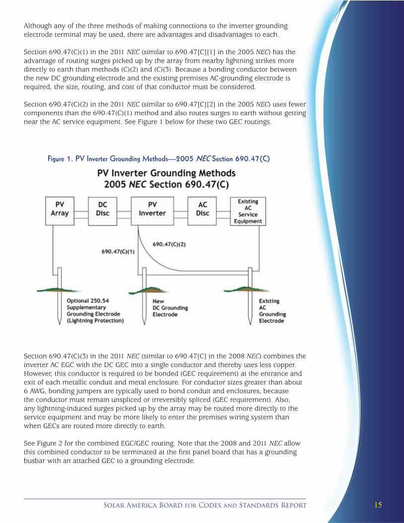
Although any of the three methods of making connections to the inverter grounding electrode terminal may be used, there are advantages and disadvantages to each. Section 690.47(C)(1) in the 2011 NEC (similar to 690.47[C][1] in the 2005 NEC) has the advantage of routing surges picked up by the array from nearby lightning strikes more directly to earth than methods (C)(2) and (C)(3). Because a bonding conductor between the new DC grounding electrode and the existing premises AC-grounding electrode is required, the size, routing, and cost of that conductor must be considered.
Section 690.47(C)(2) in the 2011 NEC (similar to 690.47[C][2] in the 2005 NEC) uses fewer components than the 690.47(C)(1) method and also routes surges to earth without getting near the AC service equipment. See Figure 1 below for these two GEC routings.
Figure 1. PV Inverter Grounding Methods—2005 NEC Section 690.47(C)
Section 690.47(C)(3) in the 2011 NEC (similar to 690.47[C] in the 2008 NEC) combines the inverter AC EGC with the DC GEC into a single conductor and thereby uses less copper. However, this conductor is required to be bonded (GEC requirement) at the entrance and exit of each metallic conduit and metal enclosure. For conductor sizes greater than about 6 AWG, bonding jumpers are typically used to bond conduit and enclosures, because the conductor must remain unspliced or irreversibly spliced (GEC requirement). Also, any lightning-induced surges picked up by the array may be routed more directly to the service equipment and may be more likely to enter the premises wiring system than when GECs are routed more directly to earth.
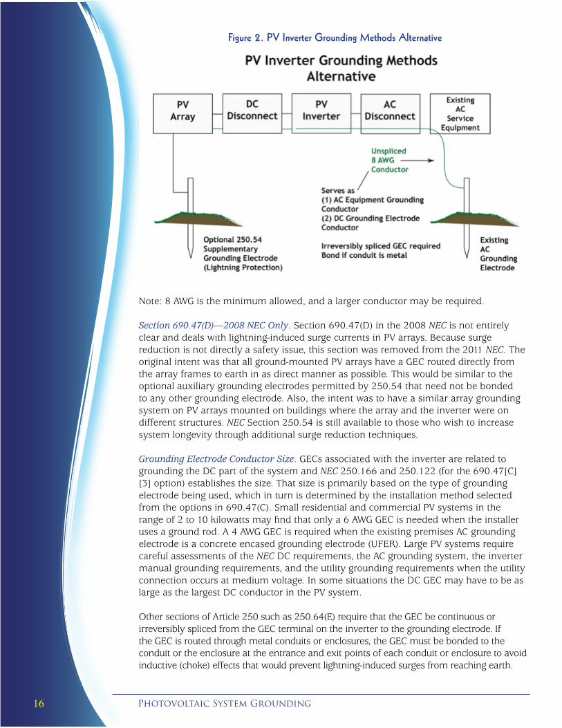
See Figure 2 for the combined EGC/GEC routing. Note that the 2008 and 2011 NEC allow this combined conductor to be terminated at the first panel board that has a grounding busbar with an attached GEC to a grounding electrode.
16 Photovoltaic System Grounding
Figure 2. PV Inverter Grounding Methods Alternative
Note: 8 AWG is the minimum allowed, and a larger conductor may be required.
Section 690.47(D)—2008 NEC Only. Section 690.47(D) in the 2008 NEC is not entirely clear and deals with lightning-induced surge currents in PV arrays. Because surge reduction is not directly a safety issue, this section was removed from the 2011 NEC. The original intent was that all ground-mounted PV arrays have a GEC routed directly from the array frames to earth in as direct manner as possible. This would be similar to the optional auxiliary grounding electrodes permitted by 250.54 that need not be bonded to any other grounding electrode. Also, the intent was to have a similar array grounding system on PV arrays mounted on buildings where the array and the inverter were on different structures. NEC Section 250.54 is still available to those who wish to increase system longevity through additional surge reduction techniques.
Grounding Electrode Conductor Size. GECs associated with the inverter are related to grounding the DC part of the system and NEC 250.166 and 250.122 (for the 690.47[C][3] option) establishes the size. That size is primarily based on the type of grounding electrode being used, which in turn is determined by the installation method selected from the options in 690.47(C). Small residential and commercial PV systems in the range of 2 to 10 kilowatts may find that only a 6 AWG GEC is needed when the installer uses a ground rod. A 4 AWG GEC is required when the existing premises AC grounding electrode is a concrete encased grounding electrode (UFER). Large PV systems require careful assessments of the NEC DC requirements, the AC grounding system, the inverter manual grounding requirements, and the utility grounding requirements when the utility connection occurs at medium voltage. In some situations the DC GEC may have to be as large as the largest DC conductor in the PV system.
Other sections of Article 250 such as 250.64(E) require that the GEC be continuous or irreversibly spliced from the GEC terminal on the inverter to the grounding electrode. If the GEC is routed through metal conduits or enclosures, the GEC must be bonded to the conduit or the enclosure at the entrance and exit points of each conduit or enclosure to avoid inductive (choke) effects that would prevent lightning-induced surges from reaching earth.
17Solar America Board for Codes and Standards Report
Ungrounded Systems
When an installation meets the requirements of 690.35, the PV system can be ungrounded. Inverters designed for use with ungrounded systems will have no requirement for a GEC. However, the NRTLs and the manufacturers have not yet fully understood the UL 1741 requirements, and non-isolated (transformerless) inverters are on the market with a marked grounding electrode terminal. This creates an issue for the PV installer because NEC 110.3(B) requires compliance with the product labels and that would imply that a DC GEC is needed. Neither the NEC nor UL Standard 1741 specifically require one, however. Installing the unneeded GEC will usually do no harm, other than increase the price of the system, and may provide a lower impedance path to earth for surge currents.
Color Codes. The NEC does not prescribe color codes for ungrounded DC conductors, except that they may not be green, green with yellow stripes, white, gray, or have three white stripes. By convention, red would normally be used for the positive conductor and black for the negative conductor. However, conductors with colored insulation should be avoided when exposed to UV radiation, as they may not be as durable as black insulated conductors.
Ambiguity in the NEC. The current wording of 690.47(B) in the NEC relating to DC systems leaves a hole in the NEC with respect to ungrounded PV systems. The NEC may require a DC grounding electrode on ungrounded PV systems for the purpose of DC equipment grounding. In actuality, with a common equipment grounding busbar or connection between the DC equipment grounding terminals and the AC equipment grounding terminals, the exposed metal surfaces of the DC equipment are grounded when the AC EGC is connected to the grounding system at the AC main bonding jumper. The following proposal for the 2014 NEC has been submitted to clarify this area:
690.47(B) (NEW)Add a new third paragraph as follows:
Ungrounded dc PV arrays connected to utilization equipment with common ac and dc equipment grounding terminals shall be permitted to have equipment grounding requirements met by the ac equipment grounding system without the requirement for a dc grounding electrode conductor or grounding system.
Substantiation: The first paragraph of 690.47(B), as currently written, applies to stand-alone ungrounded dc PV systems where a new grounding electrode and grounding electrode conductor are required. There is no requirement directly addressing the ungrounded PV array connected to a utility-interactive inverter as allowed by 690.35.
Most ungrounded PV arrays will be connected to utility-interactive inverters and those inverters have common ac and dc equipment grounding terminals. The PV array dc equipment grounding conductors, when connected to such inverters, have the array dc equipment grounding conductors connected to earth through the ac equipment grounding system and the existing ac grounding system. Additional grounding electrodes and grounding electrode conductors are not required, but may be used.
Of course, meeting system equipment grounding requirements in this manner may not be the best method to reduce potential damage from lightning-induced current surges and overvoltage. (Note the use of the phrase “shall be permitted,” which indicates that this will be an option.) The optional system grounding of 250.54 should be considered in high lightning areas, although a fully engineered and listed lightning protection system would be a better choice than simply adding electrodes.
18 Photovoltaic System Grounding
Microinverters And Ac Pv Modules— Different Requirements
PV modules and microinverters combined/assembled in the field or at the dealer or distributor may not meet the intent, definition, or requirements associated with true AC PV modules as defined in 690.2 and in 690.6. These combinations of devices also may not meet the requirements for an AC PV module in UL Standard 1741.
As of early 2012, there is no specific size associated with either microinverters or AC PV modules. The power outputs are increasing with nearly every new product. In most cases, NEC requirements that apply to the larger string and central inverters will also apply to the microinverter. Microinverters have similar AC output characteristics, connections, and code requirements to AC PV modules.
Always follow the instructions supplied with the listed product (NEC 110.3[B]). The material below is not a substitute for compliance with the instruction manual, the NEC, or local codes.
Grounding. Both the AC PV module and the microinverter will require equipment grounding connections if there is any exposed metal in these devices. A GEC connection is required when the microinverter connects either the negative or positive inverter input conductor (from the PV module) to ground through the inverter case. Many microinverter manufacturers will ground the positive DC conductor to allow the inverter to be paired with the widest range of PV modules.
Equipment/Safety Grounding. The AC output circuit cable of some microinverters does not have an EGC. This EGC must be started (originated) in the transition box on the roof where each set of inverters has the final factory AC output cable connected to another wiring system. This AC EGC must be routed back to an AC grounding point as it is in any other AC circuit. There is no requirement that it be unspliced, and the size will typically be determined per Table 250.122. The AC EGC must also be routed to each metal inverter enclosure either through the AC output cable or as a separate conductor connected to a lug on that enclosure.
System Grounding. True AC PV modules, with no readily accessible DC conductors or DC disconnects, will normally not require a GEC or GEC terminal.
Under UL Standard 1741, if the microinverter isolates the DC grounded input conductor (assuming a grounded PV module) from the AC output (with a transformer or other method), the microinverter must have a DC GEC running from the grounding electrode terminal on the microinverter case to a DC grounding electrode. If the microinverter operates the PV module as an ungrounded system (neither positive nor negative connected to ground), then no GEC would be required.
Section 690.47(C) in the 2008 NEC and 690.47(C)(3) in the 2011 NEC permit the use of a combined AC EGC and DC GEC from the inverter. UL 1741 requires the DC GEC terminal on the outside of the inverter. If this combined conductor option is elected, then the most stringent requirements that apply to either the EGC or the GEC must be followed. When routed in conduit (for physical protection), a GEC as small as 8 AWG may be allowed (250.166). The combined conductor may be this size assuming that the required EGC is 8 AWG or less (250.122). Section 250.64 requires that the GEC (and hence the combined conductor) be bonded to the input and output of each metal conduit (where used) as well as any metal enclosure that it is routed through until it gets to the main grounding
19Solar America Board for Codes and Standards Report
bar in the AC supply equipment. The bonding requirement and 8 AWG size would rule out the use of 10 AWG type non-metallic sheathed cable for the AC output circuit. The bonding requirement may also be cumbersome to implement multiple times, and the routing of this combined conductor may induce lightning surges to enter the main load center and other branch circuits. Furthermore, if the existing AC grounding electrode for the structure is encased in concrete, the GEC from the inverter may have to be a 4 AWG conductor (250.166).
The alternate methods of routing the GEC allowed in 690.47(C) in the 2011 NEC might provide better solutions. These solutions and their pros and cons were covered above in the Systems Grounding part of this report.
AC PV Module Grounding—A Gray Area. Combinations of a microinverter and a PV module with exposed DC connectors and DC conductors between the PV module and the microinverter are being certified/listed as AC PV modules. Some of these products have instruction manuals that say the microinverter may not be removed from the PV module. Other manuals give specific instructions for removing the microinverter from the PV module for repair. At issue is the definition of an AC PV module as a factory assembled unit and the potential need to meet all DC NEC requirements for these products with exposed DC connectors and DC conductors. Connectors are subject to loosening, corrosion, or intentional opening in the field. Connectors and conductors are also exposed to environmental degradation, ground faults, and animal damage.
Another concern is the microinverter-to-PV module frame bonding when the mechanical/electrical connection is broken in the field. When the microinverter is replaced, the bonding connection must be reestablished following the instructions in the product manual, which have been evaluated during the NRTL certification/listing of the product. In the future, these issues will be addressed in UL 1741 and possibly in the NEC.
At this time, the best strategy for installers is to follow the instruction manual and labels found on the certified/listed product as required by NEC section 110.3(B)
20 Photovoltaic System Grounding
Ground Faults And Ground-Fault Protection Devices
Ground Faults—More Than the NEC Definition
The NEC defines a ground fault as an unintentional connection between an ungrounded conductor and a grounded conductor or surface (Article 100 Definitions). Although this definition is suitable and adequate for electrical systems sourced by the utility, generator, or batteries, it does not fully address the limited fault current scenarios found in PV systems.
A ground fault in a PV system (and other electrical systems) also occurs when any circuit conductor (either ungrounded or grounded) comes in contact with an EGC or grounded surface. Because there is only one system bonding jumper in each system, when a ground fault occurs with a grounded conductor, the current that normally flows only in the grounded circuit conductor will now also flow in the EGC and the main bonding jumper. The current will flow in the two paths in inverse proportion to the resistance of the parallel paths. Currents in unintended paths can start fires if conductors or other metallic paths overheat or if the voltage at an open circuit is sufficient to sustain an arc.
Ground-Fault ProtectionBecause PV modules are current-limited sources and PV current is a function of the environmental effects of irradiance and temperature, overcurrent protection in PV circuits is not designed and installed like it is in voltage-sourced power systems. Normally, OCPD in PV systems is 156% of the rated Isc of the module. In many fault scenarios, there is insufficient available Isc to activate OCPD. Although OCPDs are required to deal with some overcurrent issues in PV systems, other methods are required to effectively deal with ground faults in the DC circuits.
Section 690.5 of the 1987 NEC added new requirements intended to reduce fire hazards resulting from ground faults in PV systems mounted on the roofs of dwellings. The intent is not to provide shock protection, because the 5 milliamperes (the current level required for AC ground-fault circuit interrupters [GFCI] anti-shock protection) level of protection would not be possible on a PV array with distributed leakage currents. The requirement is also not to be confused with a DC GFPD. The GFPD is intended to deal only with ground faults (both grounded conductor and ungrounded conductor) and not line-to-line faults.
The requirements for the GFPD were modified in subsequent revisions of the NEC. The requirements for the device in the current NEC are:
• Detect a ground fault
• Interrupt the fault current
• Indicate that there was a ground fault
• Open the ungrounded PV conductors or cause the inverter or charge controller to stop exporting power.
In the 2008 NEC, the GFPD requirement was extended to all PV systems with a few minor exceptions.
In a manner similar to other requirements in the NEC, there is no specific mention of how to implement the requirement. It should also be noted that neither is there any specification on the magnitude of the ground-fault current nor an exemption for grounded conductor ground faults.
21Solar America Board for Codes and Standards Report
Most currently available inverters, both stand-alone and utility-interactive, use a transformer that isolates the DC grounded circuit conductor (usually the negative) from the AC grounded circuit conductor (usually the neutral). With this transformer isolation, the DC side of a PV system may be considered similar, but not identical, to a separately derived system and, as such, must have a single DC bonding connection (DC system bonding jumper) that connects the DC grounded circuit conductor to a common grounding point where the DC EGCs and the DC GEC are connected. Like grounded AC systems, only a single DC system bonding connection is allowed. If more than one bonding connection were allowed on either the AC or DC side of the system, unwanted currents would flow in the EGCs, which violates NEC Section 250.6.
Due to the above isolation and the fact that the DC circuits of the PV system are bonded to ground in one place only, there will normally be no current (only leakage current) flowing to ground. Today, a typical GFPD detects excessive current flowing to ground using an OCPD or current sensor placed in the DC system bonding conductor or a differential current sensor placed so that it senses the difference between the PV+ and PV- currents coming from the PV array to the inverter.
Currently, GFPDs are available as both separate devices for adding to stand-alone PV systems and as internal circuits integrated into most utility-interactive inverters or other PV equipment. The GFPD that monitors current in the DC system bonding jumper often serves as that connection and opens the connection when a ground fault is detected. In other designs, the DC system bonding jumper is not opened to interrupt the fault currents, and the GFPD acts by disconnecting both of the current-carrying conductors from the PV array.
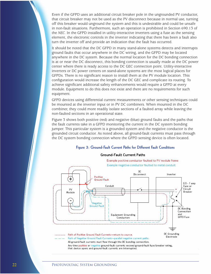
In any ground-fault scenario on the DC side of a grounded PV system, ground-fault currents from any source (PV modules or batteries in stand-alone systems) must eventually flow through the DC system bonding jumper on their way from the energy source through the fault and back to the energy source. This includes single ground faults involving the ungrounded conductor or the grounded conductor faulting to ground. In grounded conductor ground faults, the fault path creates parallel paths for the grounded conductor currents—one path through the grounded conductor and one path through the fault path. The fault path current will flow through the DC bonding connection. Double ground faults, either in a single source or output circuit or in a separate source or output circuit, are beyond the ability of any equipment to deal with at this time, and are not addressed in the NEC or in UL standards.
To meet the NEC Section 690.5 requirements, a GFPD using the DC system bonding jumper has a 0.5- to 5-amp overcurrent device installed in that bonding connection. When the DC ground-fault currents exceed the trip current rating of the device, it opens. By opening, the overcurrent device interrupts the ground-fault current as required in NEC Section 690.5. If a circuit breaker serves as the overcurrent device, the tripped position of the breaker handle provides the indicating function. When a fuse is used, an additional electronic monitoring circuit in the inverter provides an indication that there has been a ground fault. In some cases, a mechanical blown fuse indicator activating an associated switch provides a blown fuse indication. The indication function is also an NEC 690.5 requirement. Automatic resetting is not allowed for these devices.
In some designs, in which the GFPD uses a circuit breaker as the sensing device, an additional circuit breaker may be mechanically connected (common handle/common trip) to the sensing circuit breaker. These types of GFPDs are commonly found in stand-alone PV systems. This additional circuit breaker, usually rated at 100 amps and used as a switch rather than an overcurrent device, is connected in series with the ungrounded circuit conductor from the PV array. Multiple poles of a single circuit breaker can be used to simultaneously disconnect different subarrays of the same system. In this manner, when a ground fault is sensed and interrupted, the added circuit breaker(s) disconnects the PV array from the rest of the circuit, providing an additional indication that something has happened that needs attention.
22 Photovoltaic System Grounding
Even if the GFPD uses an additional circuit breaker pole in the ungrounded PV conductor, that circuit breaker may not be used as the PV disconnect because in normal use, turning off this breaker would unground the system and this is undesirable and could be unsafe in non-fault situations. Furthermore, such an operation is prohibited in Section 690.13 of the NEC. In the GFPD installed in utility-interactive inverters using a fuse as the sensing element, the electronic controls in the inverter indicating that there has been a fault also turn the inverter off and provide an indication that the fault has occurred.
It should be noted that the DC GFPD in many stand-alone systems detects and interrupts ground faults that occur anywhere in the DC wiring, and the GFPD may be located anywhere in the DC system. Because the normal location for the DC bonding connection is at or near the DC disconnect, this bonding connection is usually made at the DC power center where there is ready access to the DC GEC connection point. Utility-interactive inverters or DC power centers on stand-alone systems are the most logical places for GFPDs. There is no significant reason to install them at the PV module location. This configuration would increase the length of the DC GEC and complicate its routing. To achieve significant additional safety enhancements would require a GFPD at every module. Equipment to do this does not exist and there are no requirements for such equipment.
GFPD devices using differential current measurements or other sensing techniques could be mounted at the inverter input or in PV DC combiners. When mounted in the DC combiner, they could more readily isolate sections of a faulted array while leaving the non-faulted sections in an operational state.
Figure 3 shows both positive (red) and negative (blue) ground faults and the paths that the fault currents take in a GFPD monitoring the current in the DC system bonding jumper. This particular system is a grounded system and the negative conductor is the grounded circuit conductor. As noted above, all ground-fault currents must pass through the DC system bonding connection where the GFPD sensing device is often located.
Figure 3: Ground-Fault Current Paths for Different Fault Conditions
23Solar America Board for Codes and Standards Report
These devices are capable of interrupting ground faults occurring anywhere in the DC system, including faults at the PV array or anywhere in the DC wiring from the PV module to the inverter and to the battery in stand-alone systems. Systems that have isolation components such as some charge controllers or DC-to-DC converters may have a more limited view of fault locations. All of this can be done from many possible locations in the DC circuit. Including these GFPDs on all PV systems reduces the potential for fires.
Keeping the PV source and output conductors outside of a dwelling until the point of first penetration and requiring the readily accessible DC disconnect at this point also enhances the safety of the system. See Section 690.14 of the NEC for details. The 2005 NEC and subsequent editions of the NEC allow conductors in metallic raceways to be routed inside the structure (690.31[E]). The use of metallic raceways for the DC source and output circuits will facilitate ground-fault detection if the conductors in those grounded conduits fault to the conduit.
During a ground fault, if the DC system bonding connection is opened or all conductors are disconnected from a faulted circuit, and if the ground fault cures itself for some reason (e.g., an arc extinguishes), the faulted circuit in the DC system remains ungrounded until the GFPD system is reset. An ungrounded conductor-to-ground fault may allow the grounded conductor (now ungrounded) to go to the open-circuit voltage with respect to ground. This is addressed by the marking requirements of Section 690.5(C). A very high value (>50k) resistor is usually built into the GFPD and this resistor bleeds off static electric charges and keeps the PV system loosely referenced to ground (but not solidly grounded) during ground fault actions. The resistor value is selected so that any fault currents still flowing are only a few milliamps and are too low to be a fire hazard.
But Problems Still Exist. Although the NEC and UL standards require that ground faults be detected, some implementations of the GFPD may not recognize ground faults in all circuits throughout the PV array. Active analysis of these issues is ongoing and UL Standards and/or the NEC will be modified to rectify this problem, which is addressed in the following paragraphs.
During the daily cycle of zero current to rated current in bright sun, an ungrounded conductor ground fault will usually source enough current to activate the ground-fault detector. The detection current for the ground-fault system as currently implemented must be set high enough (0.5 to 5 amps) to prevent nuisance trips due to expected and normal leakage currents. These leakage currents increase in wet weather, with array size, and as the array ages. However, lower currents (below the detection value) that are associated with grounded conductor and ungrounded ground faults will go undetected. In the case of grounded conductor ground faults, the faults may exist for significant periods of time before being detected or found because there is typically no loss of performance because the currents from the source still get to the inverter. A ground fault in an ungrounded conductor that is below the detection level of the GFPD may be sensed as a loss of power in that circuit, however, provided that the data monitoring system has sufficient sensitivity and granularity.
If a grounded conductor ground fault exists and a second ground fault occurs in an ungrounded conductor, the GFPD will activate, but this action may force high fault currents through the grounded conductor ground fault. This grounded conductor fault path may be incapable of withstanding these high currents and pose a fire hazard. See the Solar ABCs paper on the Ground-fault Protection Blind spot (Brooks, 2012). Second ungrounded conductor ground faults in a system with an initial ungrounded conductor fault can be treated as an independent event and usually will not interact with the first fault. The exception is that the two ground-fault currents may add to a sufficient value to be sensed by the GFPD.
24 Photovoltaic System Grounding
Ungrounded Systems. Section 690.35 of the NEC also requires ungrounded systems to have a GFPD. These detection systems are mainly electronic in nature and may not have the issues of the GFPD on grounded systems. These systems have to operate with leakage currents and impedances and those factors will change with system age and environmental conditions. The most common GFPD approach in ROW is electronic impedance measurements between array conductors and ground, a strategy that has proven effective. Monitoring and tracking the impedances over time may allow ground faults to be more readily detected in the presence of time varying leakage currents. With equipment modifications and redesign, and when implemented prior to exporting current from the array, such devices could be applied to existing grounded PV systems.
25Solar America Board for Codes and Standards Report
THE CONNECTION TO EARTH
The grounding electrode is the final connection to the earth and carries currents from lighting-induced surges as well as from possible cross connections with other electrical power systems to the earth. The NEC discusses a number of different metallic materials and components that may be used as grounding electrodes as well as various restrictions on their installation. Using more than one of these electrodes (encouraged by the NEC) forms a grounding electrode system.
Grounding electrodes include rods, pipes, plates, rings, concrete encased electrodes, building steel, and other devices. Rod-type electrodes must be stainless steel or copper or zinc coated steel and may use other materials when certified/listed.
The resistance from the grounding electrode to earth must be 25 ohms or less (250.53[A][2]). If this criterion is not met, an additional grounding electrode must be added more than six feet away to form a grounding electrode system. There is no requirement to measure this resistance to ground and it is rarely measured because it requires specialized equipment. For that reason, many local codes, particularly in the dry Southwest, require that two grounding electrodes always be installed.
GEC Size. The apparent quality of the grounding electrode connection to earth, all other things being equal, appears to be the rationale for sizing the GEC. The better the presumed contact with earth, the larger the required GEC. Section 250.166 establishes the sizes for a DC GEC and 250.66 establishes the size for an AC GEC. Both appear to require increased sizes for the grounding electrodes that provide the better contact with earth.
No Fault Currents. It should be noted that ground-fault currents do not normally travel through the GEC to the grounding electrode and then to the earth. These ground-fault currents typically flow through the equipment grounding system and the circuit conductors. An exception occurs when a grounding electrode system involves building steel where multiple conductive paths in the equipment grounding system and grounding electrode system may be involved with fault currents.
26 Photovoltaic System Grounding
UTILITY VS NEC REQUIREMENTS
The NEC covers the premises wiring requirements up to the “service point,” which is an NEC definition for the point at which utility requirements end and NEC requirements begin. Utility electrical installation requirements are established by the National Electrical Safety Code (NESC) (a registered trademark of the Institute of Electrical and Electronic Engineers [IEEE]) and various other IEEE standards.
The three-phase multi-grounded system is referenced in both the NESC and the NEC. The NESC sets the ground rules for practical safeguarding of persons during the installation, operation, or maintenance of electric supply and communication lines and associated equipment. The NESC contains the basic provisions that are considered necessary for the safety of employees and the public under the specified conditions.
In the grounding arena, if the utility has grounded any of the service conductors in their distribution system (usually at the local distribution transformer secondary), the NEC requires that these grounded conductors be connected to earth (grounded) again at the service disconnect. There is typically no EGC between the premises electrical system and the utility electrical system. In some cases, like a three-wire delta service, there may not even be a grounded circuit conductor such as the grounded neutral conductor on a four-wire wye service.
On larger systems, particularly those with an interface at medium voltage, utility grounding requirements may be applicable to the grounding methods used at the service entrance. IEEE 142—The Green Book (IEEE, 2007) provides some of the highly technical explanations for grounding these types of systems and some utilities may require that these practices be followed before allowing the PV interconnection.
27Solar America Board for Codes and Standards Report
Acronyms
AC alternating current AHJ authority having jurisdiction ANSI American National Standards Institute AWG American wire gauge DC direct current EGC equipment grounding conductor GEC grounding electrode conductor GFCI ground-fault circuit interrupter (AC Systems) GFPD ground-fault protection device Hz hertz IEEE Institute of Electrical and Electronic Engineers Isc short circuit current NEC National Electrical Code NESC National Electrical Safety Code NFPA National Fire Protection Association NRTLs Nationally Recognized Testing Laboratories OCPD overcurrent protective device OSHA U.S. Occupational Safety and Health Administration ROW rest of world UL Underwriters Laboratories
28 Photovoltaic System Grounding
References
Ball, G., Zgonena T., & Flueckiger C. (2012). Photovoltaic module grounding: Issues and recommendations. Solar ABCs. www.solarabcs.org/grounding
Brooks, B. (2012). The ground-fault protection blind spot: Safety concern for larger PV systems in the U.S. Solar ABCs. www.solarabcs.org/blindspot
Institute of Electrical and Electronic Engineers (IEEE). (2007). Recommended practice for grounding of industrial and commercial power systems (IEEE 142-The Green Book). http://ieeexplore.ieee.org/xpl/mostRecentIssue.jsp?punumber=4396961
International Association of Electrical Inspectors. (2011). Soares grounding and bonding.
National Fire Protection Association (NFPA). (2011). National Electrical Code® (NEC®), NFPA 70.
National Fire Protection Association (NFPA). (2011). National Electrical Code Handbook.
Underwriters Laboratories (UL). (2002). UL 1703: Standard for safety for flat-plate photovoltaic modules and panels. (Revised dated May 8, 2012). http://ulstandardsinfonet.ul.com/scopes/1703.html
UL. (2010). UL 1741: Standard for safety for inverters, converters, controllers and interconnection system equipment for use with distributed energy resources. http://ulstandardsinfonet.ul.com/scopes/scopes.asp?fn=1741.html
UL. (2010). UL 2703: Rack mounting systems and clamping devices for flat-plate photovoltaic modules and panels. http://ulstandardsinfonet.ul.com/outscope/2703.html

Solar America Board for Codes and Standardswww.solarabcs.org