Embed Size (px)
Citation preview

PHYS117B.02 Exam II Practice Solutions
1. Shown in the Figure below is a loop of wire that lies in a horizontal plane.You have a standard bar magnet that you will move either up or downand in the process either insert or remove it from the loop. This problemconcentrates on knowing which way the current flows in the loop (i.e. allanswers are either “clockwise” or “counter-clockwise”). Which way does
N
S
EW
the current flow if you:
(a) Insert the North end of the magnet into the loop from below.
ANSWER: clockwise. Inserting the North end of the bar magnetfrom below increases the magnetic field flux through the loop outof the page. To compensate for this increase, the magnetic fieldproduced by the induced current in the loop has to point into thepage. Using your right hand: point the thumb into the page ( this isthe direction of Binduced) ). Your curved fingers show the directionof the current that will produce such a field.
(b) Insert the South end of the magnet into the loop from below.
ANSWER: counter-clockwise. Inserting the South end of the barmagnet from below increases the magnetic field flux through the loopinto of the page. To compensate for this increase, the magnetic fieldproduced by the induced current in the loop has to point out of thepage. Using your right hand: point the thumb out of the page ( thisis the direction of Binduced) ). Your curved fingers show the directionof the current that will produce such a field.
(c) Insert the North end of the magnet into the loop from above.
ANSWER: counter-clockwise. Inserting the North end of the barmagnet from above increases the magnetic field flux through the loopinto of the page. To compensate for this increase, the magnetic fieldproduced by the induced current in the loop has to point out of thepage. Using your right hand: point the thumb out of the page ( this
1
is the direction of Binduced) ). Your curved fingers show the directionof the current that will produce such a field.
(d) Insert the South end of the magnet into the loop from above.
ANSWER: clockwise. Inserting the South end of the bar magnetfrom above increases the magnetic field flux through the loop outof the page. To compensate for this increase, the magnetic fieldproduced by the induced current in the loop has to point into thepage. Using your right hand: point the thumb into the page ( this isthe direction of Binduced) ). Your curved fingers show the directionof the current that will produce such a field.
(e) Remove the North end of the magnet from the loop from below.
ANSWER: counter-clockwise. The North pole has been in the looppointing its flux out of the page. When we remove it from below,we’ll reduce the magnetic flux through the loop pointing out of thepage. To compensate for this reduction the magnetic field producedby the induced current needs to point out of the page. Using yourright hand: point the thumb out of the page ( this is the directionof Binduced) ). Your curved fingers show the direction of the currentthat will produce such a field.
(f) Remove the South end of the magnet from the loop from below.
ANSWER: clockwise. The South pole has been in the loop, theNorth pole is below the page. When we remove the magnet frombelow, we’ll reduce the magnet-ix flux through the loop pointinginto the page. To compensate for this reduction the magnetic fieldproduced by the induced current needs to point into the page. Usingyour right hand: point the thumb into the page ( this is the directionof Binduced) ). Your curved fingers show the direction of the currentthat will produce such a field.
(g) Remove the North end of the magnet from the loop from above.
ANSWER: clockwise. The North pole has been in the loop pointingits flux into the page. When we remove it from above, we’ll reducethe magnet-ix flux through the loop pointing into the page. To com-pensate for this reduction the magnetic field produced by the inducedcurrent needs to point into the page. Using your right hand: pointthe thumb into the page ( this is the direction of Binduced) ).Yourcurved fingers show the direction of the current that will producesuch a field.
(h) Remove the South end of the magnet from the loop from above.ANSWER: counter-clockwise. The South pole has been in the looppointing the flux out of the page. When we remove it from above,we’ll reduce the magnet-ix flux through the loop pointing out of thepage. To compensate for this reduction the magnetic field producedby the induced current needs to point out of the page. Using yourright hand: point the thumb out of the page ( this is the direction
2

of Binduced) ).Your curved fingers show the direction of the currentthat will produce such a field.
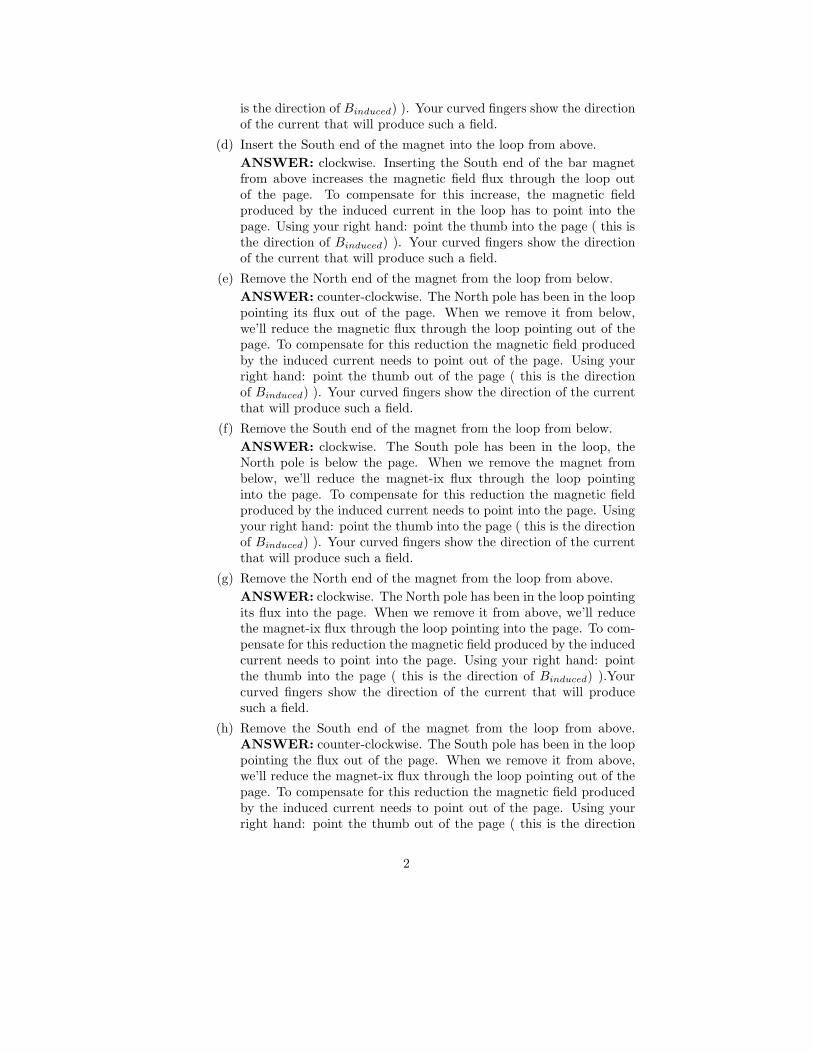
2. Shown in the Figure below is a rectangular loop of dimensions 0.20 m by0.30 m. The loop is partly filled with a magnetic field whose strength is0.25 T and is directed into the page. The loop has a resistance of 3 Ω.You grab the loop and pull it to the right with a constant speed of 0.4m/sec.
B=0.25 Tx
x
x
x
x
x
x
x
x
x
x
x
x
x
x
x
x
x
x
x
0.20 m
0.30 m
B=0x
(a) Which way does the current flow (clockwise or counter-clockwise)?
ANSWER: The loop contains magnetic field pointed into the page.When you slide it to the right, the downward flux would be reduced.The loop responds by adding additional downward field lines by mak-ing current in the clockwise direction.
(b) What is the voltage generated in the loop?
ANSWER: Here I slipped a jargon ... “voltage” = “emf”. UsingFaraday’s law, we can find the emf. The sign will show us the direc-tion of the current, but we answered that already. So we just needto find the magnitude.
ε = −dΦB
dt(1)
|ε| =dΦB
dt(2)
ΦB = BA = Blw (3)
dΦB
dt=
d(Blw)
dt= Bl
dw
dt= Blv (4)
dΦB
dt= 0.25 · 0.20 · 0.4 = 0.02V olts (5)
3
|ε| = 0.02V olts (6)
(7)
(c) What is the current in the loop?
ANSWER:
ε = IR (8)
I =ε
R(9)
I =0.02
3= 0.0066Amps = 6.6mA (10)
(d) How much force is required to keep the loop moving at 0.4 m/s?
Let’s first figure out if the magnetic field is exerting force on theloop. The loop has four wire segments, each of which carry the samecurrent. The force on a wire segment with current I is:
−→F = I
−→l ×−→
B (11)
One side of the loop is out of the field, so it experiences no force.The other two sides are parallel to each other and carry current inopposite directions. The forces on these segment will be in oppositedirections and will cancel out. For the segment on the left, the forceis pointing to the left and will not cancel out. The magnetic field isperpendicular to the wire, so the cross product gives:
F = ILB = 0.0066 · 0.20 · 0.25 = 0.000333Newtons (12)
4

3. Shown in the figure below is the view from above of a sliding bar of re-sistance R and length L. The bar is free to slide along the rails withoutfriction. The system is immersed in a magnetic field pointed out of thepage (toward you). The bar is being pulled with constant velocity v tothe bottom of the page. Answer all the following:
v
y
Sliding Bar with resistance R
L
(a) Write an expression for the flux through the loop formed by the barand wire slide for the moment when the bar’s position is “y”.
ANSWER:
ΦB = BA = BLy (13)
(b) Using your result from (a) determine an expression for the voltagegenerated in the loop as a function of the bar’s velocity.
ANSWER: The velocity
V = −dΦB
dt(14)
V = −Bldy
dt= −BLv (15)
(c) Determine the current through the bar.
ANSWER:
V = IR (16)
I =V
R(17)
I =
∣
∣
∣
∣
−BLv
R
∣
∣
∣
∣
(18)
5

The magnetic flux is increasing out of the page, so the induced currentneeds to flow clockwise to create magnetic field flux into the page.
(d) Determine the force on the bar as a function of velocity.
ANSWER: The field is perpendicular to the bar, so the magnitudeof the force is:
F = ILB (19)
F =BLv
RLB (20)
F =B2L2
Rv (21)
(e) What direction is this force (justify your response).
ANSWER:The force is in the plane of the page pointing up (oppos-ing the change). This can be seen from the vector product: currentto the left, field out of the page, force - up.
4. The circuit below begins with the switch in the open position. The batteryhas VB = 8V , the resistor has R = 2kΩ, and the inductor has L = 3mH .At time=0, the switch in the circuit is closed.
(a) Determine the time constant of this circuit.
ANSWER:
τ =L
R=
3mH
2kΩ= 1.5µsec (22)
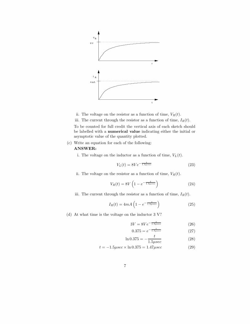
(b) Draw sketches of the time dependence of each of the following:
i. The voltage on the inductor as a function of time, VL(t).
t
VL
8 V
6
t
VR
8 V
t
RI
4 mA
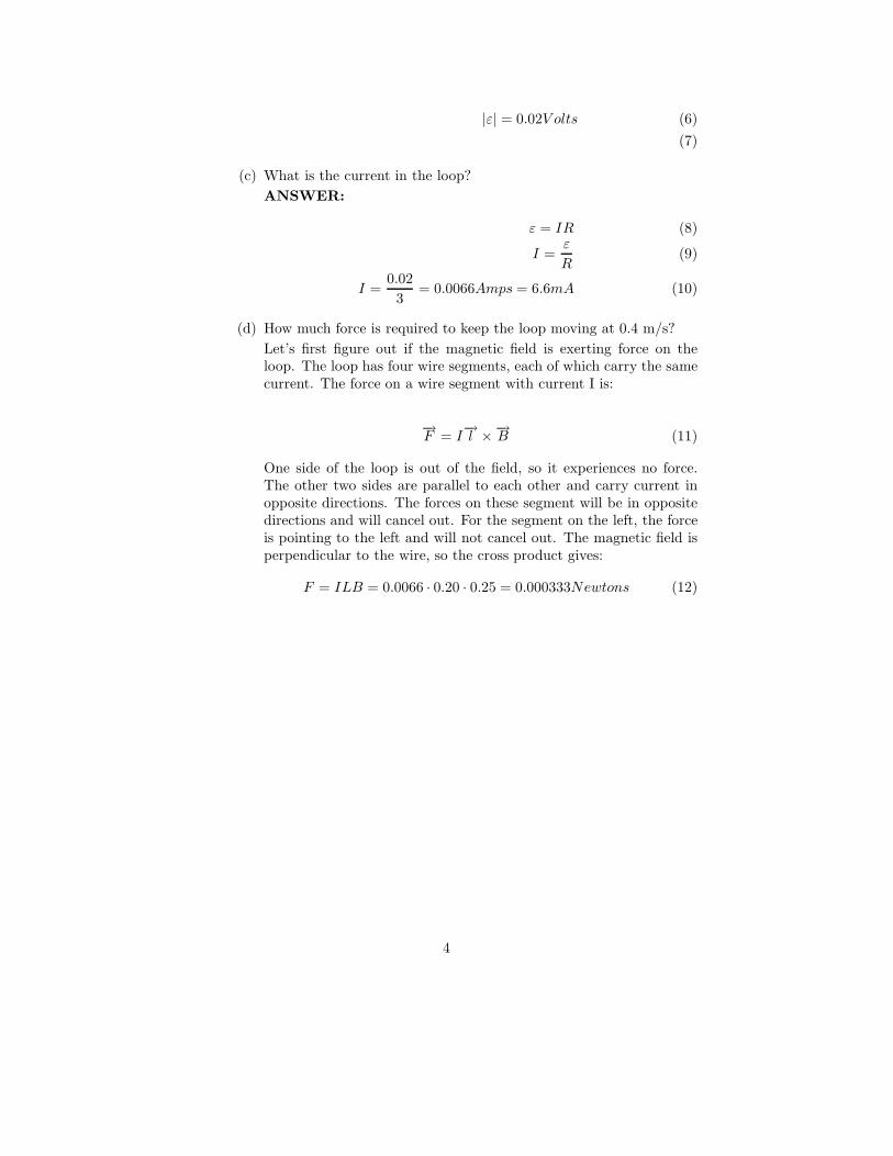
ii. The voltage on the resistor as a function of time, VR(t).
iii. The current through the resistor as a function of time, IR(t).
To be counted for full credit the vertical axis of each sketch shouldbe labelled with a numerical value indicating either the initial orasymptotic value of the quantity plotted.
(c) Write an equation for each of the following:
ANSWER:
i. The voltage on the inductor as a function of time, VL(t).
VL(t) = 8V e−t
1.5µsec (23)
ii. The voltage on the resistor as a function of time, VR(t).
VR(t) = 8V(
1 − e−t
1.5µsec
)
(24)
iii. The current through the resistor as a function of time, IR(t).
IR(t) = 4mA(
1 − e−t
1.5µsec
)
(25)
(d) At what time is the voltage on the inductor 3 V?
3V = 8V e−t
1.5µsec (26)
0.375 = e−t
1.5µsec (27)
ln 0.375 = − t
1.5µsec(28)
t = −1.5µsec× ln 0.375 = 1.47µsec (29)
7

5. A radio tuning circuit consists of a variable capacitor and an inductor.The minimum value of the capacitor is C = 4.18 pF .
(a) If the frequency on one end of the AM radio broadcast band isf = 1.6MHz and you want to make a circuit that can receive itby tuning the capacitor at its minimum value, find the inductance ofthe coil that you will need.
ANSWER: Here is an easy one. The resonance frequency of the LCcircuit depends on L and C.
ω = 1/√
LC (30)
LC = 1/ω2 (31)
L = 1/(C · ω2) (32)
Now, ω is the angular frequency and we are given the frequency f .How do I know that ? Because of the units - Hz means 1 period persecond. The angular frequency is measured in rad/s , i.e. - angle perunit time. Since 1 period is equal to an angle of 2π rad , ω = 2π f .
L = 1/(C · 4 · π2 · f2) (33)
L = 1/(4.18 × 10−12 · 4 · π2 · (1.6 × 106)2) (34)
L = 2.37mH (35)
(b) If the other end of the AM radio broadcast band is f = 540kHzwhat is the maximum value of the adjustable capacitance ?
ANSWER: This is also easy. The same relations - we just changethe value of the frequency, so we need to change something in thecircuit.We’ll change the capacitance. You can imagine that by turn-ing the knob on your radio, you are changing the overlap area of theplates of the capacitor. An then ...hey you are tuning the resonantfrequency! So, here is what we need for C to get to the other end ofthe AM range:
C = 1/[L(2π f)2] (36)
C = 1/[2.37× 10−3(2π · 540 × 103)2] (37)
C = 36.7pF (38)
I can do it in another way, not involving a numeric value for L at all.
Cnew = 1/[L(2π fnew)2] (39)
Cnew = Cold(2π fold)2/(2π fnew)2 (40)
Cnew = Cold · f2
old
f2new
(41)
(c) With the capacitor tuned as in part (a) the maximum current throughthe circuit is I = 0.85mA. What is the maximum charge on thecapacitor ?
8

ANSWER: Here we will use conservation of energy. The energy willbe converted from magnetic energy stored in the inductor to electricenergy stored in the capacitor and vice versa. We know the maximumcurrent,L and C. So we know the total energy of the system.
U =1
2LI2
max =1
2Q2
max/C (42)
Qmax = Imax
√LC (43)
Here, I can type in the numbers for L and C... but I’m lazy and Inotice that:
√LC = 1/ω = 1/(2π f) (44)
So, now I need to type less numbers, because I’m given f = 1.6MHz:
Qmax = Imax/(2π f) (45)
Qmax = 0.85 × 10⁻³/(2π1.6 × 106) (46)
Qmax = 84.5pC (47)
(d) Find the wavelengths that correspond to the two ends of the radiobroadcast band.
ANSWER: OK, whew! A very easy one:
c = λf (48)
λ =c
f(49)
λ1 =3 × 10⁸
540 × 103= 555.5m (50)
λ2 =3 × 10⁸
1.6 × 106= 187.5m (51)
(52)
9

6. You were outside your family spacecraft taking a leasurely spacewalk andyour impetulant kids speed off into the cosmos leaving you just floatingthere, about 150 billion meters from the sun. At your location, the in-tensity of sunlight is roughly 1000 W
m2 and the gravity is not completelyzero, so you start to fall toward the sun. Even though it would take a longtime to reach the sun, you are concerned that if your position changes alotyou’ll never be found.
So you take action:
(a) You calculate the average electric field of the light.
ANSWER: OK, now you should remember that the intensity ( Wm2 )
is related to the magnitude of the Pointing vector.
Thus:
I = ǫ0E2 × c (53)
E =
√
I
ǫ0c(54)
E =
√
1000
8.85 × 10−12 · 3 × 108(55)
E = 614V
m(56)
(b) You calculate the average magnetic field of the light.
ANSWER: I can write this in terms of the magnetic field:
I =B2
µ0
× c (57)
B =
√
µ0 I
c(58)
B =
√
4π × 10−7 · 1000
3 × 10⁸(59)
B = 0.00000205Tesla (60)
Hey, I can do this much easier. Aren’t the magnetic field and electricfield in an EM wave proportional via:
E = cB (61)
B =E
c(62)
B =614
3 × 108= 0.00000205Tesla (63)
Um, yup :)
10

(c) You calculate the pressure applied to a reflective solar sail.
ANSWER: The pressure applied by EM waves varies from P = Ic
to P = 2Ic
as the substance to which the light is applied goes fromabsorbative to reflective. Yours is reflective:
P =2I
c(64)
P =2000
3 × 10⁸(65)
P = 0.00000666Pa(N
m2) (66)
(d) You calculate the size of a solar sail necessary to exactly balance thesun’s gravity.
ANSWER: Well, due to gravity you get F = GmMr2 . Due to the
solar wind, you get F = Pressure × Area. Set these equal to avoidfalling into the sun!
GmM
r2= PA (67)
A =GmM
Pr2(68)
A =6.67 × 10−11 · 100 · 2 × 1030
0.00000666 · (150 × 109)2(69)
A = 88942m2 (70)
As a square, this would be 300 meters on each side. See how badthe Star Wars Part-II Solar Sail was...WAY WAY too small.
(e) What do you write on the sail?
ANSWER: Your situation is rather hopeless, so I leave it up to youto figure out the best strategy.
Oh, you and your space suit have a total mass of 100 kg and you happento remember that the mass of the sun is 2× 1030 kg and the gravitationalconstant G = 6.67 × 10⁻¹¹Nm2/kg2.
11

7. Shown in the figure below is a system containing an object, and two lenses.Use the shapes of the lenses in the figure to decide whether they areconverging or diverging optical elements.
15 cm 4 cm
|f|=8 cm |f|=30 cm
(a) Find the image location and magnification of the first lens (assumingthat only this lens exists). Specify this image location, di1, as somenumber of centimeters to the left or to the right of this lens.
ANSWER:
do1 = 15cm f1 = 8cm (71)
1
15+
1
di1
=1
8(72)
di1 = 17.14cm (73)
m1 = −17.14cm
15cm= −1.143 (74)
(right of lens)
(b) The image of the first lens acts as the object for the second. Findthe location and magnification of the image produced by the secondlens. Specify this image location, di2, as some number of centimetersto the left or to the right of this lens.
ANSWER:
do2 = −13.14cm f2 = −30cm (75)
1
−13.14+
1
di2
=1
−30(76)
di1 = 23.38cm (77)
m1 = − 23.38cm
−13.14cm= 1.779 (78)
(right of lens)
12

(c) Calculate the total magnification of this entire system.
ANSWER:
mTOT = m1 × m2 = −2.034 (79)
(d) Is the final image real or virtual?
ANSWER: real
8. Shown in the figure below is a system containing an object, a lens, and amirror. This is a 3-pass system in that light goes from the object, throughthe lens, off the mirror, and back through the lens a second time.Use the shape of the objects in the figure to decide whether they areconverging or diverging optical elements.
20 cm 8 cm
R = 10 cm|f|=5 cm
(a) Find the image location and magnification of the first lens (assumingthat only this lens exists).
ANSWER: Because the object is on the incoming side, do1 is posi-tive, i.e. do1 = +20cm. Because the lens is diverging, the focal lengthis negative, i.e. f1 = −5cm. Using 1
do1
+ 1
di1= 1
f1
, we have
1
20+
1
di1
=1
−5(80)
1
di1
=1
−5− 1
20(81)
1
di1
= −0.25 (82)
di1 = −4cm (83)
m1 = − di1
do1
= −−4
20= +0.2 (84)
13

The negative sign for di1 means that the image is NOT on the out-going side, so the image is 4 cm to the left of the lens on the firstpass.
(b) The image of the lens acts as the object for the mirror. Find thelocation and magnification of the image produced by the mirror.
ANSWER: Since the image of the lens is 4 cm to the left of the lensitself, the object distance for the mirror is 8cm + 4cm = 12cm. Thisdistance is positive since this “object” is on the incoming side of thelight, i.e. do2 = +12cm. The focal length of a curved mirror is 1
2of
the radius. Also, since this mirror is a converging device, the focallength is positive. Thus, f2 = +5cm. Plugging these in:
1
12+
1
di2
=1
5(85)
1
di2
=1
5− 1
12(86)
1
di2
= 0.11666 (87)
di2 = 8.5714cm (88)
m2 = − di2
do2
= −8.5714
12= −0.714 (89)
Since this image distance is positive, the image is on the outgoingside of the mirror at a distance of 8.57 cm. The outgoing side of themirror is to the left of the mirror.
(c) Lastly, the image from the mirror acts as the object for the light’ssecond pass through the lens. Find the location and magnification ofthe image produced in this step.
ANSWER: This one is a bit tricky. Since the image of the mirror(object for the lens) is 8.5714 cm away from the mirror and thelens is only 8 cm from the mirror, the object for the lens is NOT
on the incoming side. Thus, the object distance will be negative,do3 = −0.5714cm. Again, the lens is diverging, so that the focallength is f = −5cm. OK, putting this in:
1
−0.5714+
1
di3
=1
−5(90)
1
di3
=1
−5− 1
−0.5714(91)
1
di3
= 1.55 (92)
di3 = 0.645cm (93)
m3 = − di3
do3
= − 0.645
−0.5714= 1.129 (94)
14

This image is on the outgoing side meaning to the left of the lens.
(d) Calculate the total magnification of this entire system. Is the finalimage real or virtual?
ANSWER: mTOT = m1×m2×m3 = 0.2×−0.714×1.129 = −0.161
This image is real since it is on the outgoing side of the last opticalelement, and the minus sign tells us that it is inverted as it shouldbe for real images.
9. A particular person’s nearsighted eye has a near point of 12 cm and a farpoint of 17 cm. You will place a lens 2 cm in front of their eye. Answerall the following:
(a) Do you use a converging or diverging lens?
ANSWER: This near-sighted person should have a diverging lens.
(b) What is the focal length of the chosen lens?
ANSWER: Well, this person has a far point of 17 cm. Normally,the eye should have a far point of infinity. So, what we do with thelens is we take objects at infinity, and put the image 17 cm in frontof this person’s eye.
Now, since the lens is not touching the eye (these are glasses notcontacts), we need an image that is 17-2=15 cm from the lens. Notethat this image will NOT be on the outgoing side, so we concludedi = − 15cm when do = ∞.
1
do
+1
di
=1
f(95)
1
∞ +1
−15=
1
f(96)
− 1
15=
1
f(97)
f = −15cm (98)
(c) What is this person’s new nearpoint?
ANSWER: Well, this person will reach the nearpoint when theimage from the glasses is 12 cm in front of the eye, or 10 cm in frontof the lens di = − 10 cm.
1
do
+1
di
=1
f(99)
1
do
+1
−10=
1
−15(100)
15

1
do
=1
10− 1
15(101)
do = 30cm (102)
Wait, what if this poor person wants to see an object when it iscloser than 30 cm? Well, they take off their glasses!! How manytimes have you seen a person look at something closely by taking offtheir glasses? Each such time, you were witnessing a near-sightedperson.
10. Shown in the figure below is a water glass at two different moments. Inthe first moment (left figure) the water glass is empty and the light raystrikes the bottom corner as shown. In the second moment, the glass hasbeen filled with water (n=1.33). As a result, the light ray has been bent.
1θ
Light Ray
Empty water glass
1θ
Light Ray
θ2
Full water glass
15 cm
8 cm x
n=1.33
(a) Determine the angle θ1 as shown in the left figure.
ANSWER: Examining the figure closely, we see that the angle θ1
is also the upper angle in the triangle formed by the right ray andthe left and bottom sides of the glass (using vertical angles). In thiscase, we see that tan θ1 = 8cm
15cm. Solving this we find that θ1 = 28.1o.
(b) Determine the angle θ2 as shown in the right figure.
ANSWER: Using Snell’s law:
n1 sin θ1 = n2 sin θ2 (103)
1 × sin 28.1o = 1.33 × sin θ2 (104)
0.354 = sin θ2 (105)
θ2 = 20.74o (106)
(c) Determine the distance x shown in the right figure.
16

ANSWER: Examining the triangle, we see the following:
tan θ2 =x
15cm(107)
x = 15cm × tan θ2 (108)
x = 15cm × tan 20.74o (109)
x = 5.68cm (110)
11. As shown in the figure below, a small boy has lost his toy at the bottomof a pool (nwater = 1.33). When he shines his flashlight as shown, hecan see the toy.
1.5 m
1 m
3.0 m
1
2
θ
θ
x
(a) What is the angle of incidence, θ1, of his light upon the water?
ANSWER:
tan θ1 =3.0
1.0(111)
θ1 = 71.6o (112)
(b) What is the angle of refraction θ2?
ANSWER:
n1 sin θ1 = n2 sin θ2 (113)
1.0 sin71.6o = 1.33 sin θ2 (114)
θ2 = 45.5o (115)
(c) What is the distance from the water’s edge, x, to the lost toy?
ANSWER:
x = 3m + l (116)
tan θ2 =l
1.5(117)
l = 1.5 tan θ2 (118)
l = 1.5 tan 45.5o (119)
l = 1.53m (120)
x = 4.53m (121)
17

12. Shown in the figure below is Young’s two-slit experiment. Monochromaticlight of wavelength λ = 0.633µm comes in from the left and passes throughthe two (very narrow) slits. The result is a pattern of bright and darkbands visible on a screen 5 meters away from the two slits. WARNING:
this drawing is not to scale.
Bright
Dark
Bright
Dark
3 cm
5 meters
d
(a) Determine the distance, d, between the two slits. ANSWER: Thedistance labelled in the figure (3 cm) is the distance to the first brightband. This band follows the relation d sin θ = λ. The angle to thisband can be found as follows:
tan θ =3cm
5m=
0.03m
5m(122)
θ = 0.344o (123)
d sin θ = λ (124)
d =λ
sin θ=
0.633µm
sin 0.344o= 105.5µm (125)
(b) If the light is changed to green light, λ = 0.532µm, the interferencepattern will change. What is the location, y, of the first dark bandusing this light.
ANSWER: The dark bands follow the relation d sin θ =(
n + 1
2
)
λwhere n = 0,±1,±2, .... The first dark band is n = 0 or d sin θ = 1
2λ.
Using this with the new wavelength yields:
d sin θ =1
2λ (126)
105.5µm sinθ =1
2× 0.532µm (127)
sin θ =1
2× 0.532µm
105.5µm(128)
sin θ = 0.00252 (129)
sin θ = 0.00252 (130)
θ = 0.1445o (131)
tan θ =y
5meters(132)
y = 5meters × tan 0.1445o = 0.0126m = 1.26cm (133)
18
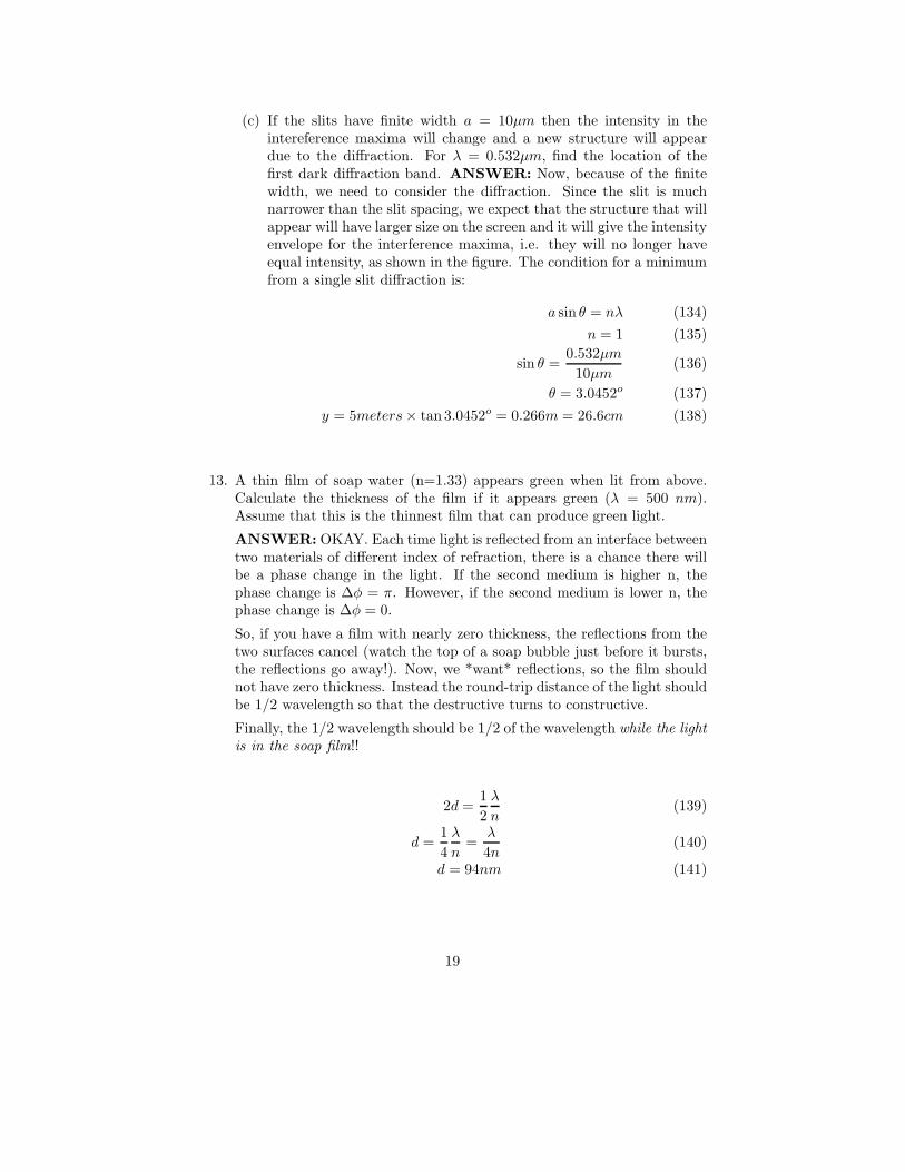
(c) If the slits have finite width a = 10µm then the intensity in theintereference maxima will change and a new structure will appeardue to the diffraction. For λ = 0.532µm, find the location of thefirst dark diffraction band. ANSWER: Now, because of the finitewidth, we need to consider the diffraction. Since the slit is muchnarrower than the slit spacing, we expect that the structure that willappear will have larger size on the screen and it will give the intensityenvelope for the interference maxima, i.e. they will no longer haveequal intensity, as shown in the figure. The condition for a minimumfrom a single slit diffraction is:
a sin θ = nλ (134)
n = 1 (135)
sin θ =0.532µm
10µm(136)
θ = 3.0452o (137)
y = 5meters× tan 3.0452o = 0.266m = 26.6cm (138)
13. A thin film of soap water (n=1.33) appears green when lit from above.Calculate the thickness of the film if it appears green (λ = 500 nm).Assume that this is the thinnest film that can produce green light.
ANSWER: OKAY. Each time light is reflected from an interface betweentwo materials of different index of refraction, there is a chance there willbe a phase change in the light. If the second medium is higher n, thephase change is ∆φ = π. However, if the second medium is lower n, thephase change is ∆φ = 0.
So, if you have a film with nearly zero thickness, the reflections from thetwo surfaces cancel (watch the top of a soap bubble just before it bursts,the reflections go away!). Now, we *want* reflections, so the film shouldnot have zero thickness. Instead the round-trip distance of the light shouldbe 1/2 wavelength so that the destructive turns to constructive.
Finally, the 1/2 wavelength should be 1/2 of the wavelength while the light
is in the soap film!!
2d =1
2
λ
n(139)
d =1
4
λ
n=
λ
4n(140)
d = 94nm (141)
19

14. Assume that three perfect polarizers are placed in sequence and receiveincoming light from one side. The first polarizer has it’s optic axis orientedvertically. The second is oriented 30 degrees to one side of vertical. Thethird is oriented horizontally.
(a) What fraction of the incoming light gets through the first polarizer?
For any polarizer the outgoing intensity is related to the incoming in-tensity via the formula Iout = Iin cos2 φ. Here φ is the angle betweenthe polarization of the light and the axis of the polarizer. Oops!In the first stage the incoming light is unpolarized. This means φtakes all possible angles. However, we know about the average value:⟨
cos2 φ⟩
= 1
2. Thus:
I1 = I0
⟨
cos2 φ⟩
(142)
I1 = I0
1
2(143)
Fraction =I1
I0
=1
2(144)
(b) What fraction of the incoming light gets through both the first andsecond polarizer?
In this case the calculation is simpler:
I2 = I1 cos2 φ (145)
I2 = I1 cos2 30o = I1
(√3
2
)2
(146)
I2 = I1
3
4(147)
I2 = I0
1
2
3
4(148)
Fraction =I2
I0
=1
2
3
4=
3
8(149)
(c) What fraction of the incoming light gets through the first, second,and third polarizers?
Again, a simple case:
I3 = I2 cos2 φ (150)
I3 = I2 cos2 60o = I2
(
1
2
)2
(151)
I3 = I2
1
4(152)
20

I3 = I0
3
8
1
4(153)
Fraction =I2
I0
=3
8
1
4=
3
32(154)
(d) How much light would get through if the second and third polarizerswere exchanged?
Nothing!!
(e) Which way are the polarizers in your sunglasses oriented. Explainwhy.
Glare comes mostly from reflections off of horizontal surfaces. Thisglare is highly polarized parallel to the surface (i.e. horizontally).To cut the glare, you orient the axis of your polarizing singlassesvertically.
(f) Explain how polarizing glasses are used to view high quality 3Dmovies.
3D movies operate on the principle of sending different images intoeach eye. The images are selected so that they view the same scenefrom different angles. To make a high quality 3D movie, you use twopsojectors sending light to the same screne. The two projectors sendpolarizations that are perpendicular to each other. By using “specialglasses” (i.e. with polarizing filters over the two eyes) you can see thedepth of the image. All one does is match the polarization directionof projector 1 to the left eye, and projector 2 to the right eye. Bottomline is different images to different eyes and a 3D movie results.
21