Embed Size (px)
Citation preview
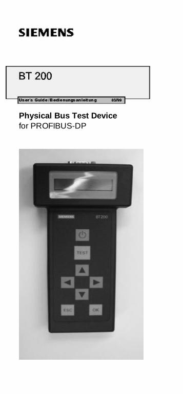
Physical Bus Test Devicefor PROFIBUS-DP
BT 200 03/99 English
(S)J31069-D0075-U001-A1-7618 Page 1
BT 200Physical Bus Test Device
for PROFIBUS-DP
Table of Contents
1 DESCRIPTION ...........................................2
2 COMMISSIONING ......................................3
3 NORMAL MODE.........................................4
3.1 WIRING TEST............................................................... 53.2 ERROR MESSAGES OF THE WIRING TEST .................. 6
4 SPECIALIST MODE....................................8
4.1 OPERATOR CONTROL ................................................. 84.2 STATION (RS 485) TEST..........................................104.3 BRANCH TEST...........................................................114.4 DISTANCE..................................................................124.5 REFLECTION TEST.....................................................134.6 SERVICE....................................................................14
5 MAINTENANCE AND TROUBLE-SHOOTING ................................................. 15
5.1 CHARGING STATUS OF THE BATTERY.......................155.2 CHANGING THE BATTERY..........................................155.3 SELF-TESTS ..............................................................165.4 ERROR CORRECTION TABLE.....................................17
6 ACCESSORIES AND REPLACEMENTPARTS........................................................ 18
7 TECHNICAL DATA................................... 19
English 03/99 BT 200
(S)J31069-D0075-U001-A1-7618Page 2
1 Description
Purpose of the BT 200The BT 200 offers diagnostics for PROFIBUS-DP systems without having to use additionalmeasuring aids (e.g., PC or oscilloscope).
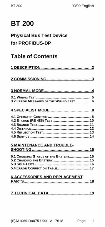
Operator control elements and display
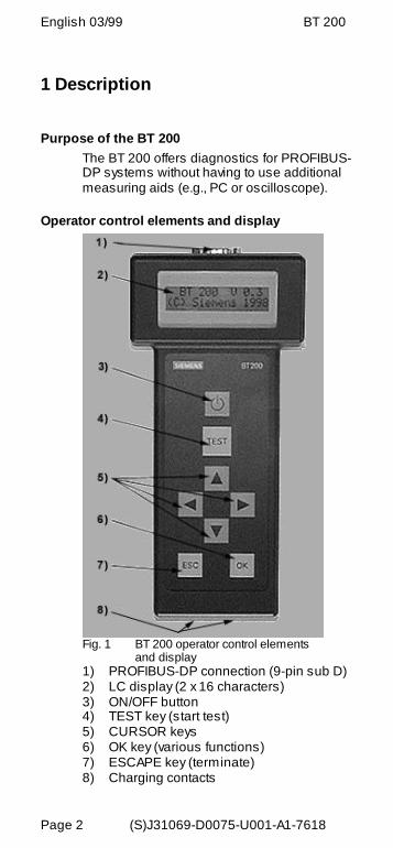
Fig. 1 BT 200 operator control elements and display
1) PROFIBUS-DP connection (9-pin sub D)2) LC display (2 x 16 characters)3) ON/OFF button4) TEST key (start test)5) CURSOR keys6) OK key (various functions)7) ESCAPE key (terminate)8) Charging contacts
BT 200 03/99 English
(S)J31069-D0075-U001-A1-7618 Page 3
2 CommissioningBefore initial commissioning, check your de-livery, and charge the battery.
Scope of deliveryThe delivery includes:- 1 BT 200- 1 battery- 1 test plug connector (wiring test)- 1 test cable, length: 2 m- 1 user's guide
Charging the battery- Open the battery compartment (see
chapter on changing the battery), andcheck to detemine whether the battery isinstalled. Install the battery if necessary.
- Charge battery of the BT 200 via char-ging shell (approx. 4 hours).
U Attention!The battery is always delivered uncharged.The charging shell is not included and mustbe ordered separately.
- Remove the BT 200 from the chargingshell. The device is ready for operation.
English 03/99 BT 200
(S)J31069-D0075-U001-A1-7618Page 4
3 Normal Mode
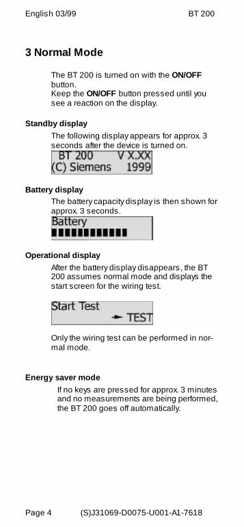
The BT 200 is turned on with the ON/OFFbutton.Keep the ON/OFF button pressed until yousee a reaction on the display.
Standby displayThe following display appears for approx. 3seconds after the device is turned on.
Battery displayThe battery capacity display is then shown forapprox. 3 seconds.
Operational displayAfter the battery display disappears, the BT200 assumes normal mode and displays thestart screen for the wiring test.
Only the wiring test can be performed in nor-mal mode.
Energy saver modeIf no keys are pressed for approx. 3 minutesand no measurements are being performed,the BT 200 goes off automatically.
BT 200 03/99 English
(S)J31069-D0075-U001-A1-7618 Page 5
3.1 Wiring Test
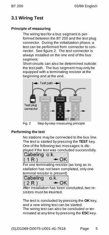
Principle of measuringThe wiring test for a bus segment is per-formed between the BT 200 and the test plugconnector. During the initialization phase, atest can be performed from connector to con-nector. See figure 2. The test connector isalways installed on the one end of the bussegment.Short circuits can also be determined outsidethe test path. The bus segment may only beequipped with a terminating resistor at thebeginning and at the end.
Fig. 2 Step-by-step measuring principle
Performing the testNo stations may be connected to the bus line.The test is started by pressing the TEST key.One of the following two messages is dis-played if the test was concluded successfully.
For one terminating resistor (as long as in-stallation has not been completed, only oneterminal resistor is present)
After installation has been concluded, two re-sistors must be inserted.
The test is concluded by pressing the OK key,and a new wiring test can be started.The wiring test can also be concluded or ter-minated at any time by pressing the ESC key.
English 03/99 BT 200
(S)J31069-D0075-U001-A1-7618Page 6
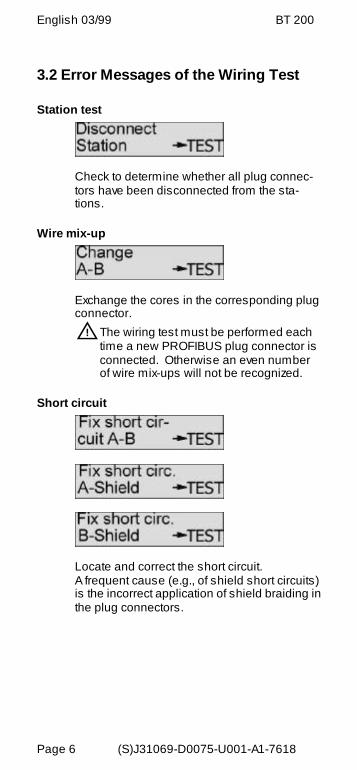
3.2 Error Messages of the Wiring Test
Station test
Check to determine whether all plug connec-tors have been disconnected from the sta-tions.
Wire mix-up
Exchange the cores in the corresponding plugconnector.U The wiring test must be performed each
time a new PROFIBUS plug connector isconnected. Otherwise an even numberof wire mix-ups will not be recognized.
Short circuit
Locate and correct the short circuit.A frequent cause (e.g., of shield short circuits)is the incorrect application of shield braiding inthe plug connectors.
BT 200 03/99 English
(S)J31069-D0075-U001-A1-7618 Page 7
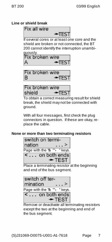
Line or shield break
If several cores or at least one core and theshield are broken or not connected, the BT200 cannot identify the interruption unambi-guously.
To obtain a correct measuring result for shieldbreak, the shield may not be connected withground.
With all four messages, first check the plugconnectors in question. If these are okay, re-place the cable.
None or more than two terminating resistors
Page with the "→ ""← " keys.
Place a terminating resistor at the beginningand end of the bus segment.
Page with the "→ ""← " keys.
Remove or deactivate all terminating resistorsexcept the two at the beginning and end ofthe bus segment.
English 03/99 BT 200
(S)J31069-D0075-U001-A1-7618Page 8
4 Specialist ModeYou can switch from normal mode to special-ist mode by pressing ESC and OK at thesame time.The following functions are available in spe-cialist mode.- Wiring test. See normal mode.
- Station test- Wire mix-up- Short circuit- Line or shield break- None or more than two
- Station test (RS 485 test)- Branch test- Distance measurement- Reflection test- Service menu
4.1 Operator ControlThe BT 200 is menu-controlled via the inputkeys of the sealed keyboard (figure 1).
CursorThe current cursor position in the display isshown as a flashing arrow and indicates thefunction which is being performed.
BT 200 03/99 English
(S)J31069-D0075-U001-A1-7618 Page 9
Menu itemsMenu items are selected with the cursor andactivated with the OK key . The ESC key canbe used to terminate a running function or tojump back to the higher-level menu item.
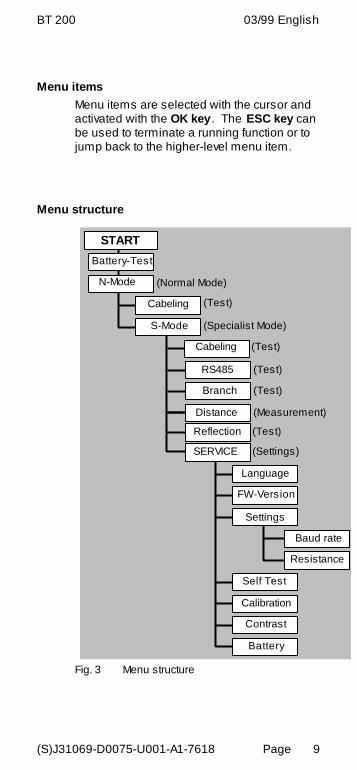
Menu structure
START
Battery-Test
N-Mode
Cabeling (Test)
(Normal Mode)
S-Mode (Specialist Mode)
RS485
Branch
Distance
SERVICE
(Test)
(Test)
(Measurement)
(Settings)
Language
FW-Version
Settings
Baud rate
Resistance
Self Test
Calibration
Battery
Contrast
Cabeling (Test)
Reflection (Test)
Fig. 3 Menu structure
English 03/99 BT 200
(S)J31069-D0075-U001-A1-7618Page 10
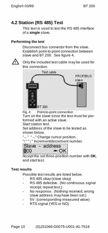
4.2 Station (RS 485) TestThis test is used to test the RS 485 interfaceof a single slave.
Performing the testDisconnect bus connector from the slave.Establish point-to-point connection betweenslave and BT 200. See figure 4.
U Only the included test cable may be used forthis connection.
Fig. 4 Point-to-point connectionTurn on the slave since the test must be per-formed with an active slave.Start station test.Set address of the slave to be tested asshown below."← " "→ " Change cursor position."↑" "↓" Increment/decrement number.
Accept the set three-position number with OK,and start test.
Test resultsPossible test results are listed below.- RS 485 okay (slave okay)- RS 485 defective. (No continuous signal
receipt; repeat test.)- No response. (Nothing received; wrong
slave address may have been set.)- 5V : (corresponding measured value)- RTS signal (YES or NO)
BT 200 03/99 English
(S)J31069-D0075-U001-A1-7618 Page 11
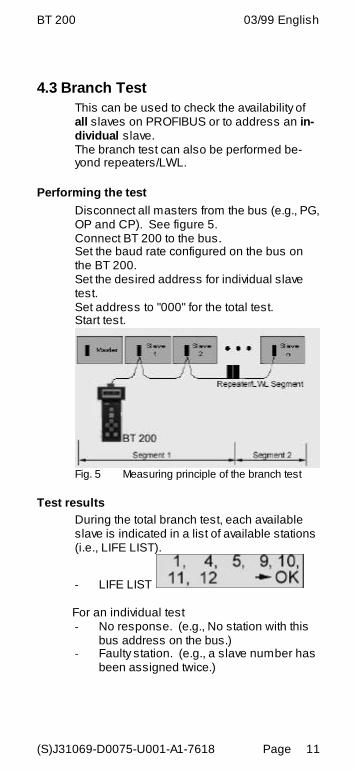
4.3 Branch TestThis can be used to check the availability ofall slaves on PROFIBUS or to address an in-dividual slave.The branch test can also be performed be-yond repeaters/LWL.
Performing the testDisconnect all masters from the bus (e.g., PG,OP and CP). See figure 5.Connect BT 200 to the bus.Set the baud rate configured on the bus onthe BT 200.Set the desired address for individual slavetest.Set address to "000" for the total test.Start test.
Fig. 5 Measuring principle of the branch test
Test resultsDuring the total branch test, each availableslave is indicated in a list of available stations(i.e., LIFE LIST).
- LIFE LIST
For an individual test- No response. (e.g., No station with this
bus address on the bus.)- Faulty station. (e.g., a slave number has
been assigned twice.)
English 03/99 BT 200
(S)J31069-D0075-U001-A1-7618Page 12
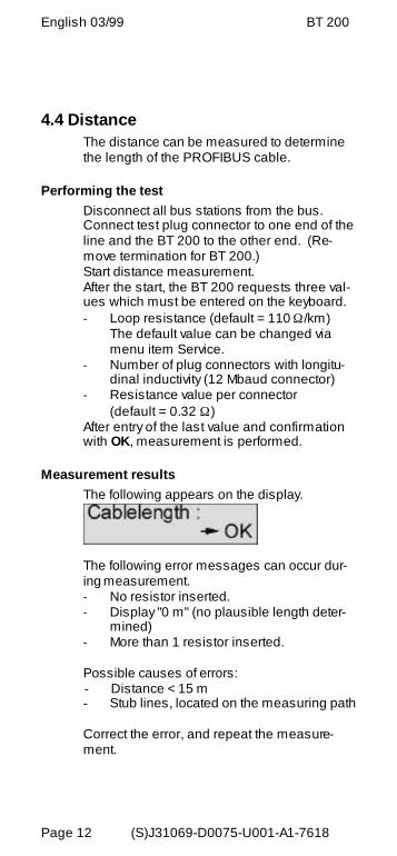
4.4 DistanceThe distance can be measured to determinethe length of the PROFIBUS cable.
Performing the testDisconnect all bus stations from the bus.Connect test plug connector to one end of theline and the BT 200 to the other end. (Re-move termination for BT 200.)Start distance measurement.After the start, the BT 200 requests three val-ues which must be entered on the keyboard.- Loop resistance (default = 110 Ω/km)
The default value can be changed viamenu item Service.
- Number of plug connectors with longitu-dinal inductivity (12 Mbaud connector)
- Resistance value per connector(default = 0.32 Ω)
After entry of the last value and confirmationwith OK, measurement is performed.
Measurement resultsThe following appears on the display.
The following error messages can occur dur-ing measurement.- No resistor inserted.- Display "0 m" (no plausible length deter-
mined)- More than 1 resistor inserted.
Possible causes of errors:- Distance < 15 m- Stub lines, located on the measuring path
Correct the error, and repeat the measure-ment.
BT 200 03/99 English
(S)J31069-D0075-U001-A1-7618 Page 13
4.5 Reflection TestThe reflection test can be used to determinefaults (e.g., short circuits and interruptions) orto confirm the distance measurement.
Reflexions can occur in the following situa-tions:- Stub lines exist.- Too many terminating resistors have
been inserted, or none have been in-serted.
- Change to a wrong type of cable occurswithin the measuring path.
- Cable installation is not correct (e.g.,luster terminal connection and so on).
Performing the testDisconnect master from the bus, and makesure that no bus communication occurs.Connect BT 200 to one end of the line.Start reflection measurement.
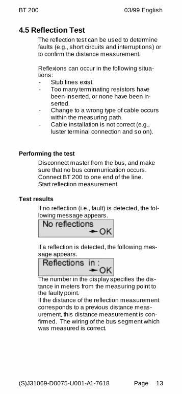
Test resultsIf no reflection (i.e., fault) is detected, the fol-lowing message appears.
If a reflection is detected, the following mes-sage appears.
The number in the display specifies the dis-tance in meters from the measuring point tothe faulty point.If the distance of the reflection measurementcorresponds to a previous distance meas-urement, this distance measurement is con-firmed. The wiring of the bus segment whichwas measured is correct.

English 03/99 BT 200
(S)J31069-D0075-U001-A1-7618Page 14
4.6 Service
SettingsThe following settings can be changed in theService menu.- Language (German/English)- Loop resistance (50 to 200 Ω/km)- Baud rate (9600 baud to 12 Mbaud)- Contrast (↑↓)
Default valuesIf you want to reset all values to their statuson delivery, keep both cursor keys pressedfor approx. three seconds after turning on thedevice.
DisplaysThe Service menu gives you the following in-formation.- Firmware version- Battery capacity
Hardware testThis tests the internal hardware.
CalibrationCalibration is not necessary when the stan-dard type-A PROFIBUS cable is used.The accuracy of distance and reflectionmeasurement is achieved by calibration with 2test cables of different known lengths.
Fig. 6 Principle of calibration
BT 200 03/99 English
(S)J31069-D0075-U001-A1-7618 Page 15
5 Maintenance and Trouble-Shooting
5.1 Charging Status of the BatteryThe charging status of the battery is indicatedfor approximately 3 seconds during startup.This display then disappears.The charging status can also be indicated viathe service menu during operation. If the battery goes dead during operation, thecharging status begins to flash.
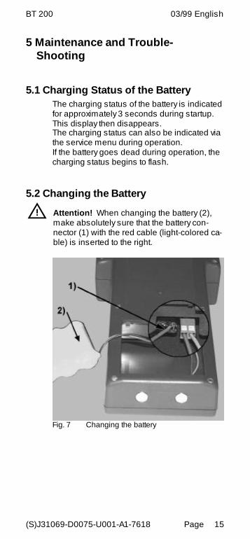
5.2 Changing the Battery
U Attention! When changing the battery (2),make absolutely sure that the battery con-nector (1) with the red cable (light-colored ca-ble) is inserted to the right.
Fig. 7 Changing the battery
English 03/99 BT 200
(S)J31069-D0075-U001-A1-7618Page 16
5.3 Self-Tests
The BT 200 performs self-tests automaticallyand on request (hardware test).
- Internal RS 485 driver test
The test is performed each time the sta-tion and branch test is called.
- RAM test A cyclic RAM test is performed.
- Flash EPROM test A cyclic EPROM test is performed.
- RS 485 driver test
The individual tests (e.g., RAM test, flashEPROM test and display key test) can also beselected from specialist mode via the HW testservice menu.
If an error is detected during the self-test, youmust proceed as shown in the error correc-tion table.
BT 200 03/99 English
(S)J31069-D0075-U001-A1-7618 Page 17
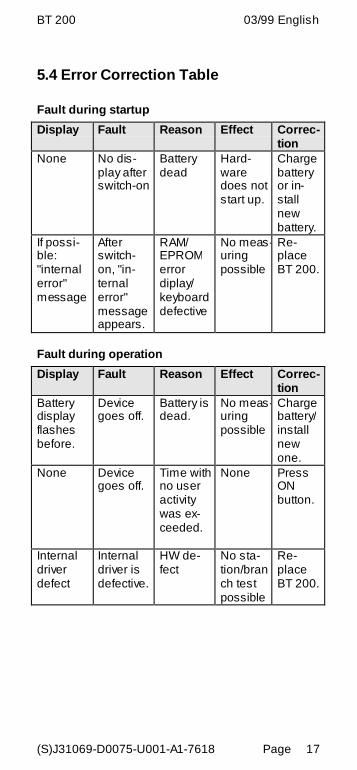
5.4 Error Correction Table
Fault during startup
Display Fault Reason Effect Correc-tion
None No dis-play afterswitch-on
Batterydead
Hard-waredoes notstart up.
Chargebatteryor in-stallnewbattery.
If possi-ble:"internalerror"message
Afterswitch-on, "in-ternalerror"messageappears.
RAM/EPROMerrordiplay/keyboarddefective
No meas-uringpossible
Re-placeBT 200.
Fault during operation
Display Fault Reason Effect Correc-tion
Batterydisplayflashesbefore.
Devicegoes off.
Battery isdead.
No meas-uringpossible
Chargebattery/installnewone.
None Devicegoes off.
Time withno useractivitywas ex-ceeded.
None PressONbutton.
Internaldriverdefect
Internaldriver isdefective.
HW de-fect
No sta-tion/branch testpossible
Re-placeBT 200.
English 03/99 BT 200
(S)J31069-D0075-U001-A1-7618Page 18
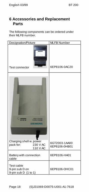
6 Accessories and ReplacementParts
The following components can be ordered undertheir MLFB number.
Designation/Picture MLFB Number
Test connector 6EP8106-0AC20
Charging shell w. powerpack for: 230 V AC
110 V AC
6GT2003-1AA006EP8106-0HB01
Battery with connectioncable
6EP8106-HA01
Test cable9-pin sub D on9-pin sub D (1 to 1)
6EP8106-OHC01
BT 200 03/99 English
(S)J31069-D0075-U001-A1-7618 Page 19
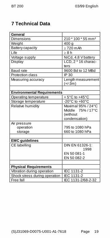
7 Technical Data
GeneralDimensions 210 * 100 * 55 mm²Weight 400 gBattery capacity ≥ 720 mAhLife ≥ 8 hVoltage supply NiCd, 4.8 V batteryDisplay LCD, 2 * 16 charac-
tersBaud rate 9600 Bd to 12 MBdProtection class IP 30Measuring accuracy Length measurement
(+/-3m)
Environmental RequirementsOperating temperature + 5°C to +45°CStorage temperature -20°C to +60°CRelative humidity Maximal 95% / 24°C
Middle 75% / 17°C(withoutcondensation)
Air pressureoperationstorage
795 to 1080 hPa660 to 1080 hPa
EMC guidelinesCE labelling DIN EN 61326-1:
1998EN 50 081-1EN 50 082-2
Physical RequirementsVibration during operation IEC 1131-2Shock stress during operation IEC 1131-2Free fall IEC 1131-2/68-2-32
English 03/99 BT 200
(S)J31069-D0075-U001-A1-7618Page 20
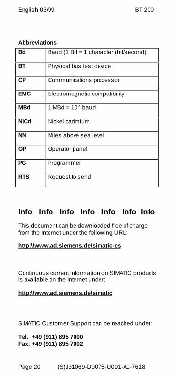
Abbreviations
Bd Baud (1 Bd = 1 character (bit/second)
BT Physical bus test device
CP Communications processor
EMC Electromagnetic compatibility
MBd 1 MBd = 106 baud
NiCd Nickel cadmium
NN Miles above sea level
OP Operator panel
PG Programmer
RTS Request to send
Info Info Info Info Info Info Info
This document can be downloaded free of chargefrom the Internet under the following URL:
http:\\www.ad.siemens.de\simatic-cs
Continuous current information on SIMATIC productsis available on the Internet under:
http:\\www.ad.siemens.de\simatic
SIMATIC Customer Support can be reached under:
Tel. +49 (911) 895 7000Fax. +49 (911) 895 7002

Siemens AGBereich Automatisierungs- und AntriebstecnikGeschäftsgebiet KombinationstechnikA&D SEPostfach 2355, D-90713 Fürth Siemens AG 1999Subject to change without prior notice
Siemens Aktiengesellschaft
Order-no.: (S)J13069-D0075-U001-A1-7618Printed in the Federal Republic of Germany


![SCA03 Profibus DP 2013-14.ppt [modalità compatibilità]€¦ · Protocollo PROFIBUS 3 PROcess FIeld BUS (PROFIBUS) FieldBus MessageFieldBus Message Process Specification (FMS) Decentralized](https://img.pdfslide.net/doc/110x75/5fc83932332b087d8a2e7d7e/sca03-profibus-dp-2013-14ppt-modalit-compatibilit-protocollo-profibus-3-process.jpg)